
Dynamic Penetration Process of Torpedo Anchors into Sand Foundation


1
Shaanxi Key Laboratory of Safety and Durability of Concrete Structures, Xijing University, Xi’an 710123, China
2
State Key Laboratory of Coastal and Offshore Engineering, Dalian University of Technology, Dalian 116024, China
3
School of Geological Engineering and Geomatics, Chang’an University, Xi’an 710054, China
*
Author to whom correspondence should be addressed.
J. Mar. Sci. Eng. 2022, 10(8), 1097; https://doi.org/10.3390/jmse10081097
Submission received: 28 June 2022
/
Revised: 27 July 2022
/
Accepted: 8 August 2022
/
Published: 11 August 2022
(This article belongs to the Special Issue New Challenges in Offshore Geotechnical Engineering Developments)
Abstract
:Torpedo anchors are a new type of anchoring system in deepwater that is much more economical than conventional anchoring methods. The dynamic penetration process is vitally important to the installation of torpedo anchors. Based on the spherical cavity expansion theory, the dynamic response characteristics of pressure-locked soils are analyzed using the Mohr-Coulomb criterion. The equations for the penetration of torpedo anchors with bullet-shaped heads are established considering rod friction. Subsequently, the analytical solutions for velocity, acceleration, and final penetration depth and the approximate analytical solution for penetration depth vs. time are obtained. The established penetration equation is solved using MATLAB software to obtain a semi-analytical solution, and the model tests on the penetration of a torpedo anchor with different initial velocities into saturated sand with different densities were conducted. A comparison of the test results shows that the analytical solution and the semi-analytical solution can well predict the model test results, indicating that the established analytical method can be used to analyze the penetration process of torpedo anchors. The research results can provide a guideline to the installation of torpedo anchors into the seabed in actual engineering.
1. Introduction
Gravity anchors are used in the mooring system of deep-sea oil and gas exploitation platforms, and their pull-out capacity is very important for engineering design. Gravity anchors such as torpedo anchors are freely released at a height of 30 to 50 m above the seafloor and penetrate into the seafloor through their own weight and velocity [1]. In 2000, Petrobras used torpedo anchors in the mooring system of a floating production, storage, and offloading (FPSO) platform. The process of the dynamic penetration of torpedo anchors into seafloor soils can be considered a penetration problem. In the military field, the penetration depth of an earth penetrator is a primary concern, for which the penetration equation has been proposed through a large number of tests. The torpedo anchor is composed of an anchor head, an anchor rod, and anchor wings, with a length of 12 to 15 m, a diameter of 762 to 1077 mm, and a weight of 240 to 950 kN [2]. The factors affecting the bearing capacity of the torpedo anchor include its own weight, the penetration depth, the mechanical properties of the seafloor soils, and the geometry of the torpedo anchor.
Chen et al. [3] conducted laboratory tests to investigate the penetration behavior and pullout capacity of a torpedo anchor under vibration, and found that the anchoring force and penetration depth of a self-penetration torpedo anchor are not restrained by water depth and drop height. Ads et al. [4] reported that the fin length of a torpedo anchor negatively correlated with penetration depth and positively correlated with maximum extraction resistance, and soil displacement increased with increasing penetration depth till full embedment. Based on the discrete element method, Zhang et al. [5] investigated the effect of anchor mass, impact velocity, and interparticle friction on the penetration process of a torpedo anchor, and concluded that the penetration increased with increasing impact velocity, and decreased with increasing interparticle friction. Based on large deformation finite element analysis, Kim et al. [6,7] reported that under the condition of the demarcation point that lies within the top stiff layer, the penetration depth of the torpedo anchor decreased with increasing of strength ratio, and the penetration is stopped between two layers when the strength ratio is higher than 15. Furthermore, an improved analytical embedment model was proposed based on strain rate dependent shearing resistance and drag resistance. Hossain et al. [8] found that the embedment depth of a torpedo anchor increased with increasing impact velocity, and decreased with increasing soil shear strength. The geometries of fin and tip had a significant effect on the bearing capacity, and the rectangular fin and conical tip proved to be more effective. Coupled with the advantages of the torpedo anchor and plate anchor, Lai et al. [9] concluded that the penetration depth of the new hybrid anchor increased with increasing impact velocity, and the new hybrid anchor could penetrate through the stiff layers. Fernandes et al. [10] concluded that the shape and mass distribution of the torpedo anchor have a remarkable effect on the directional stability, and the rear line influenced the terminal velocity and directional stability. Liu et al. [11] noted that the factors affecting the penetration of a gravity-installed anchor followed the order of undrained shear strength, impact velocity, strain rate dependency, friction coefficient, and strain-softening of soil. Based on a computational fluid dynamics approach, Raie and Tassoulas [12] developed a procedure to predict the embedment depth of the torpedo anchor, the pressure and shear distribution on the interface and in the soil. The research results provide a guideline to the installation of a torpedo anchor in a deep-sea project. Based on finite element analysis, Sabetamal et al. [13,14] revealed that a smooth discretization of the contact interface between soil and structure is a crucial factor to avoid oscillations in the prediction of a dynamic response of soil during penetration of a torpedo anchor. Based on small-scale model tests, True [15,16,17] measured the acceleration time-history curves of torpedo anchors with different anchor tip shapes during their penetration into soft clay, silt, and cement soils and established the torpedo anchor penetration equation based on Newton’s second law of motion and the theory of the ultimate bearing capacity of foundations. Considering the nonmonotonicity of the measured acceleration time-history curves and assuming that the net resistance is a composite function of the velocity squared and depth, Boguslavskii et al. [18] obtained analytical solutions for velocity, acceleration, and final penetration depth, determined the parameters in the analytical solutions based on dimensional analysis, and compared the analytical solutions with the test results. O’Loughlin et al. [19,20] studied the penetration process of torpedo anchors with a centrifuge model test and combined the existing test results to establish an empirical formula of penetration depth based on the energy balance. O’Beirne et al. [21] analyzed the entire process from release to rest of a penetrating torpedo anchor, established the calculation model for the entire release-to-rest process, and compared it with the field model test. Nazem et al. [22] used the ALE method to perform a numerical analysis on the process of the dynamic penetration of a torpedo anchor into a uniform clay layer and provided a dynamic penetration factor. Bishop et al. [23] applied the cylindrical cavity and spherical cavity expansion theory in a quasistatic state to calculate the pressure on the conical surface when a conical object is slowly pressed into a metal. Forrestal and Luk [24] applied the spherical cavity expansion theory to analyze the dynamic response of the soil at a constant cavity expansion velocity, established the equation for the vertical penetration of a long rod with a bullet-shaped tip into the soil, and provided the analytical solutions for velocity, acceleration, and penetration depth. The reliability of the calculation results was verified by actual penetration tests in the field. Shi et al. [25] used the p-α state equation and the Mohr-Coulomb-Tresca criterion to describe the constitutive relationship of dry sand, obtained the formula for calculating the depth of a projectile vertically penetrating dry sand based on the spherical cavity expansion theory, and compared the analytical results with the test results. Chian et al. [26] studied the influences of the projectile nose shape, the relative density of sand, and the projectile mass on the penetration process and found that the shape and mass of the projectile nose significantly affect the total absorption energy of sand.
The penetration of torpedo anchors into soil was mainly studied using torpedo anchors as the research object. The force was analyzed, Newton’s second law was used to establish the equation of motion, and the resistance of soil to the torpedo anchor was expressed by the ultimate tip resistance. However, the penetration process of a torpedo anchor into soil is a dynamic problem, thereby it is necessary to consider the dynamic response of soil. In addition, because the torpedo anchor has a low installation speed (20 to 30 m/s) and a large length-to-diameter ratio, the cavity expansion phenomenon is not remarkable, so the frictional resistance [27] between the anchor rod and the cavity wall cannot be ignored. In this study, the locked hydrostat model and the Mohr-Coulomb criterion are used to describe the constitutive relationship of soil. Based on the spherical cavity expansion theory and assuming that the cavity expansion velocity is constant, the governing equations for the elastic and plastic regions of soil and the normal stress of the cavity wall are established. On this basis, assuming a plane strain condition and considering the friction between the anchor rod and the cavity wall, Newton’s second law is applied to establish the equation of motion of torpedo anchors, from which the analytical solution for the torpedo anchor penetration equation is obtained. Furthermore, a semi-analytical method by MATLAB software was used to solve the penetration equation. A self-made penetration device was used to carry out a small-scale model test of torpedo anchor penetration into saturated sand. Finally, a comparison between analytical, semi-analytical, and test results were conducted to verify the feasibility of the analytical method.
2. Torpedo Anchor Penetration Equations
2.1. Calculation for the Axial Force of the Anchor Tip
It is assumed that the torpedo anchor vertically penetrates the seafloor soil with an initial velocity of V0 and proceeds to penetrate at velocity Vz. The anchor tip squeezes the soil around it to form a cavity, assuming that the anchor and surrounding soil makecontact. The diameter of the cavity gradually increases from zero to the rod diameter during the penetration process. When the velocity reaches zero, the penetration process ends. The radial stress and tangential stress acting at the anchor tip are denoted as σn and σt, respectively, as shown in Figure 1. For the torpedo anchor, the motion and final depth can be calculated when forces on the anchor tip are known. Therefore, we first model the anchor tip resistance and then calculate velocity, deceleration, and penetration depth.
Let the anchor tip be bullet-shaped, with a shape factor of CRH = ψ = s/2a, where a is the radius of the anchor rod, and s is the radius of the anchor tip arc. Let the friction coefficient between the anchor tip and the soil be η1 and the penetration velocity be Vz. The normal force acting on the segment of the anchor tip is
where .
The component in the axial direction of the anchor tip is
The upward component of tangential friction in the axial direction of the anchor tip is
Then, the resultant force in the axial direction of the anchor tip is
The total resultant force in the axial direction of the anchor tip is obtained by integrating Equation (4)
where .
2.2. Spherical Cavity Expansion Theory
2.2.1. Plastic Region Response
Let the velocity of the spherical cavity be a constant, and the radius of the spherical cavity r be increased from zero to a. It is assumed that the soil is a homogeneous, non-viscous and isotropic elastic-plastic material. The soil is saturated and incompressible, and the expansion of spherical cavity is regarded as an undrained process. As the soil cavity is expanded, it is assumed that a plastic response region and an elastic response region are formed in the soil surrounding the cavity (Figure 2). The plastic region is bounded by the radii Vt and ct, where t is the time, V is the cavity expansion velocity and c is the elastic-plastic interface velocity. It is assumed that the constitutive relationship of the soil in the plastic region is expressed by a locked hydrostat (pressure-volumetric strain) and follows the Mohr-Coulomb yield criterion. The elastic region is taken as an incompressible elastic material and the constitutive relationship follows Hooke law. In addition, the stress and strain are defined as positive when subject to compression.
For a locked hydrostat, the Mohr-Coulomb yield criterion and spherical symmetry can be expressed [24]:
where ρ0 and ρ* are the initial and locked (compacted) densities of soil, respectively, η* is the locked volumetric strain, σr and σθ are the radial and tangential components of Cauchy stress, respectively, τ0 and λ are yield parameters, and p is the average principal stress.
In the Lagrangian coordinate system, the momentum and mass conservation equations can be expressed as
where r is the radial coordinate, u is the radial displacement, and ρ is the current density.
The boundary condition at the cavity wall is
2.2.2. Elastic-Plastic Contact Surface
The Hugoniot jump condition, i.e., the momentum and mass conservation condition, is satisfied on the elastic-plastic interface
where the subscripts 1 and 2 represent the plastic and elastic regions, respectively.
2.2.3. Incompressible Elastic Region Response
The mass conservation equation is
If the convection term is ignored, the momentum equation can be expressed as
By solving Equations (6)–(11) using the similarity transformation, we can obtain the solutions corresponding to the plastic and elastic regions. In particular, the normal stress at the cavity wall can be expressed as
where , , , , , .
2.3. Penetration Equations
Let the penetration velocity of the torpedo anchor at any time be Vz; then the cavity expansion velocity is .
2.3.1. Calculation of the Axial Force of the Anchor Tip
Substituting Equation (12) into Equation (5) gives the upward resultant force in the axial direction of the anchor tip as
where ,.
2.3.2. Motion Equation of the Torpedo Anchor
Let the torpedo anchor vertically penetrate the soil with an initial velocity of V0. The seafloor surface is taken as the coordinate origin, and the positive z coordinate direction is vertically downward. Let the time be t and the penetration depth of the anchor tip be z. The equation of motion can be expressed as
where Fz is the axial force of the anchor tip and can be calculated by Equation (13). Ff is the friction between the anchor rod and the soil. Under the assumption that the anchor rod is not separated from the soil, the anchor shank bears the earth pressure in the normal direction. Let the rod-soil friction coefficient be η2 and the anchor length be L. Then, the friction Ff acting on the anchor rod can be expressed as
When z ≤ L
When z > L
where K is the earth pressure coefficient.
By substituting Equations (13) and (15) into Equation (14), we have
When z ≤ L
When z > L
Equations (17) and (18) are the equations of motion of the torpedo anchor.
To solve Equation (17), let , and .
Then, Equation (17) is reduced to a first-order ordinary differential equation
Let u = y2; then, Equation (19) can be expressed as
The initial conditions are t = 0, z = 0, and u = V02.
The general solution for Equation (20) is
The constant C3 in Equation (21) is determined by the initial conditions:
Then, the solution of Equation (19) is
where , , .
By substituting u = y2 = Vz2 into Equation (22), we have
When the penetration depth of the torpedo anchor exceeds one anchor length, the solution for Equation (18) can be obtained using the same method and expressed as
where , , .
Equations (23) and (24) show the relationships between the penetration velocity and the penetration depth when the penetration depth of the torpedo anchor is less than and greater than the anchor length, respectively.
By taking the derivative of both sides of Equations (23) and (24) with respect to t, we can obtain the relationship between the acceleration and penetration depth of the torpedo anchor as
To obtain the variation in the penetration depth with time, let ; then Equation (23) is simplified as
By integrating Equation (27), we have
There is no analytical solution for the integral on the right side of Equation (28). To obtain an approximate solution, we can approximately express e−x as .
Then, Equation (28) is approximately expressed as
When ,
The integral constant C4 in Equation (30) can be determined by the initial conditions, and the approximate solution for Equation (27) is obtained as
By substituting into Equation (31), we have
When the penetration depth z = L, the required time t1 is determined by Equation (32):
When the penetration depth z > L, Equation (24) is solved using the same method to obtain
Equations (32) and (34) represent the time needed for the penetration depth of the torpedo anchor when the penetration depth is less than and greater than the anchor length, respectively.
The final penetration depth of the torpedo anchor Zmax can be determined by Equation (23) or Equation (24):
- (1)
- Zmax ≤ L
- (2)
- Zmax > L
If the friction on the rod is not considered, the final penetration depth Zmax is
Therefore, the analytical solution for penetration depth vs. the velocity, penetration depth vs. acceleration, final penetration depth, and penetration depth vs. time of the torpedo anchor are obtained. From the engineering application viewpoint, Equations (23) and (24) can be used to calculate penetration depth vs. velocity, Equations (25) and (26) can be used to calculate penetration depth vs. acceleration, Equations (32)–(34) can be used to calculate penetration depth vs. time, and Equations (35)–(37) can be used to calculate the final penetration depth.
3. Model Test of Torpedo Anchor Penetration into Saturated Sand
3.1. Test Materials and Device
The soil samples used in the test were Fujian standard sand with a specific gravity of 2.66, and the maximum and minimum dry densities were 1.93 g/cm3 and 1.53 g/cm3, respectively. Given the particle-size distribution curve of the test sand, as shown in Figure 3, it can be concluded that the test sand was poorly graded sand. Figure 4 shows the schematic of the model test setup. The model torpedo has an anchor length of 175 mm, a diameter of 25 mm, and a mass of 235 g. The anchor tip is bullet shaped with CRH = ψ = 1.69, the anchor head is made of stainless steel, and the anchor rod is made of an aluminum alloy. The anchor rod is hollow with a built-in micro electro mechanical system (MEMS) accelerometer, which has a measurement range of ±500 g.
The plexiglass tube with an inner diameter of 220 mm, a height of 600 mm and a thickness of 10 mm was used as a model box. The hole was located in the center of the bottom, and a layer of geotextile was laid to ensure the uniformity of saturated samples. The self-designed ejection device consists of a movable support frame and an ejector. The ejector is mainly composed of a tension screw, a steel strand, an ejection rod, a model torpedo anchor bracket, a velocity control pawl, a trigger, and a velocimetry system with an ejection velocity of 15 to 30 m/s. Real-time data acquisition with the MEMS accelerometer and photogate signals was performed using the TWD dynamic data acquisition instrument (Beijing Taize Technology Development Co., Ltd., Beijing, China), with an acquisition frequency of 10 kHz, which met the test requirements. The penetration depth of the model anchor was measured by the flexible rope connected to the anchor tail.
3.2. Test Methods
The height of the samples was 500 mm. According to the designed density and loading height, the required sand mass was calculated and then loaded four times and compacted in layers. After compaction, the water was slowly supplied to the sand sample from the hole at the bottom, and back pressure was pumped on the surface of the sand to make the water rise slowly from the bottom to top. When the water level was more than 2 cm above the soil sample, the water supply was stopped and left to stand for enough time to saturate the sand sample. Subsequently, a suction ball was used to absorb the excess water on the sand surface before the penetration test.
Due to the limitations of the test conditions, it was difficult to measure the locked density of the sand. Therefore, we used the maximum dry density of the sand ρdmax to replace ρ*. In the tests, sands with four different relative densities (0.80, 0.70, 0.65, and 0.60) were labeled as A, B, C, and D, respectively, and each was assigned three velocity levels, for a total of 12 sets of tests. During the test, the model box was placed directly under the ejector, the accelerometer was preloaded into the torpedo anchor, which was installed at the bracket of the ejector, and the signal lines of the accelerometer and photogate were connected to the data acquisition instrument. The steel strand was pulled to the corresponding gear via the screw at a predesigned speed. When the signal acquisition instrument was ready, the trigger was pressed to launch the model torpedo anchor.
4. Comparison between Experimental, Analytical and Semi-Analytical Results
The strength parameters of the saturated sand with different densities were obtained by triaxial tests (Table 1). The parameters of the model torpedo anchor are shown in Table 2. According to the parameters listed in Table 1 and Table 2 and the initial penetration velocity V0 measured in the test, theoretical calculations and analyses for each penetration test were conducted. Equations (23)–(26) show the relationship between the penetration velocity, acceleration, and penetration depth of the torpedo anchor. Based on the penetration depth in the model tests, the parameters in Equations (32)–(34) were approximately determined through preliminary calculations to be A0 = 0.2579, B0 = −0.8825, and C0 = 0.9872. The friction coefficient η1 between the anchor tip and the soil and the friction coefficient η2 between the anchor rod and the soil were both experimentally determined to be approximately 0.35 [28]. The passive earth pressure coefficient was adopted. For an additional comparative analysis, the semi-analytical solutions for Equations (17) and (18) were obtained using MATLAB software.
4.1. Curves of Acceleration with Depth
The median filter method was employed to filter out the high-frequency components from the acceleration time-history signal using the built-in filter program in MATLAB. To facilitate comparison, the measured acceleration time-history curve was integrated twice to obtain the variation curve of acceleration with depth. Figure 5 shows the variation curves of acceleration with depth for saturated sands with different densities and model torpedo anchors with different initial velocities. It can be observed that the acceleration decreased with increasing depth and gradually decreased to zero. Both the analytical solutions and the semi-analytical solutions are in good overall agreement with the measured results, indicating that the cavity expansion theory can be used to analyze the dynamic penetration process of torpedo anchor. In addition, there is still some deviation between the predicted results and the measured results in the later section of the variation curve of acceleration with depth.
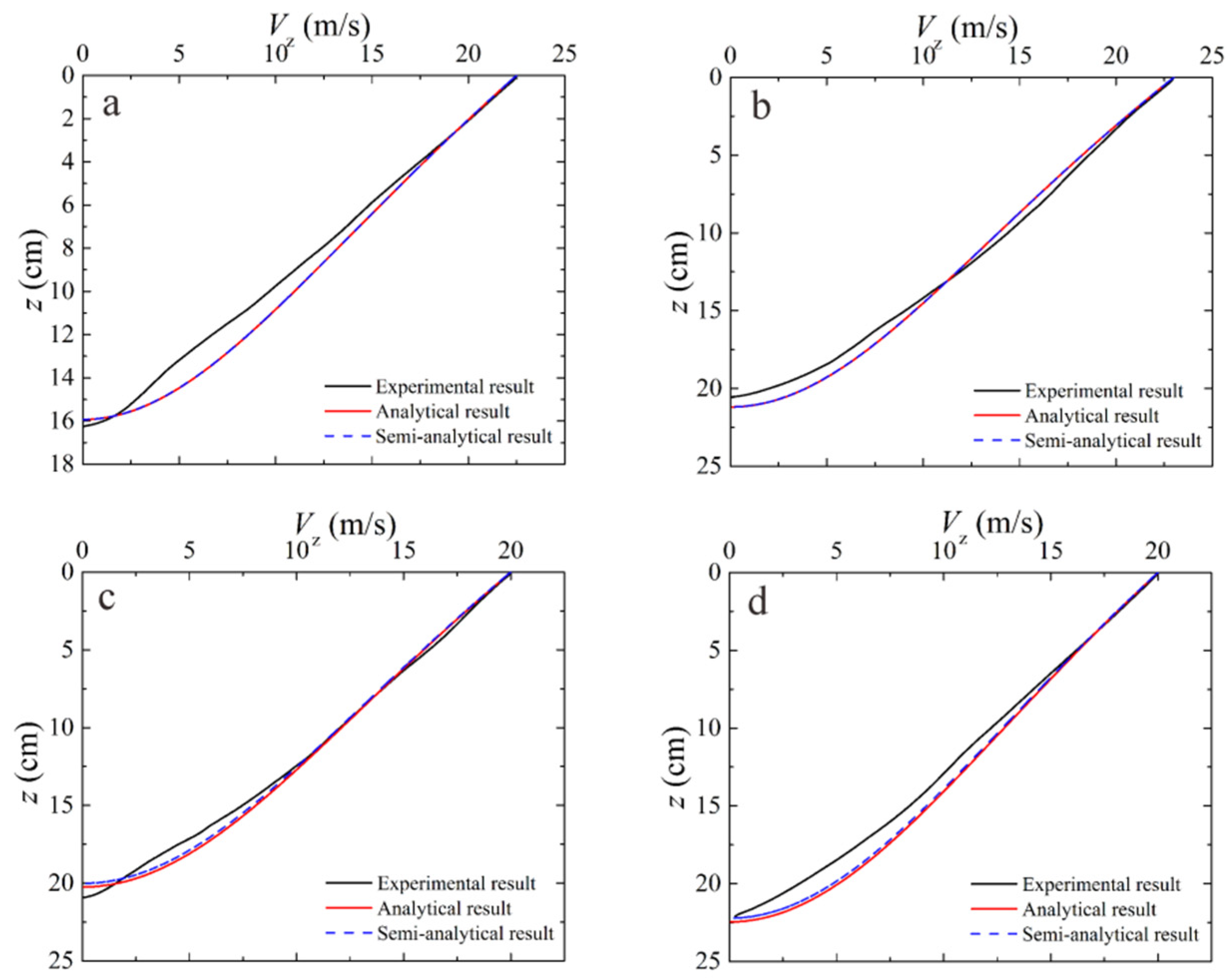
4.2. Curves of Velocity with Depth
Figure 6 shows the variation curves of velocity with depth for saturated sands with different densities and torpedo anchors with different initial velocities. As shown in the figures, the velocity decreased with increasing depth, and the analytical solution and semi-analytical solution both align well with the measured results.
4.3. Final Penetration Depth
Table 3 shows the test values of the final penetration depth of the model torpedo anchor, the integral values of the measured acceleration curve, the semi-analytical solution, and the analytical solution values under different sand densities and initial penetration velocities. As shown in Table 3, under different sand densities, the measured penetration depth is generally consistent with the calculation results based on the test acceleration time-history curve, indicating that the accelerometer used in the test has a relatively high accuracy. The analytical solution and semi-analytical solution are largely consistent with the measured results, indicating that the established equation for torpedo anchor penetration can describe the penetration process of a torpedo anchor.
5. Conclusions
By assuming that the soil is a pressure-locked material that follows the Mohr-Coulomb criterion, we analyzed the dynamic response characteristics of compressible soil based on the spherical cavity expansion theory. Under the plane strain assumption, the penetration equations of torpedo anchors were established by applying Newton’s second law. The analytical solutions for acceleration vs. depth, velocity vs. depth, and penetration depth and the approximate analytical solution for penetration depth as a function of time were given. A comparison between analytical, semi-analytical, and test results showed that the theoretical solutions are in good alignment with the measured results, indicating that the analytical solution established in this study can be used to analyze the penetration process of torpedo anchors.
Author Contributions
Conceptualization, J.Z. and G.L.; methodology, J.Z. and G.L.; validation, J.L., J.Z. and G.L.; writing—original draft preparation, G.L. and Y.Y.; writing—review and editing, J.N. and J.Z.; funding acquisition, G.L. All authors have read and agreed to the published version of the manuscript.
Funding
This research was funded by the Natural Science Basic Research Program of Shaanxi Province, grant number 2021JM-535 and the Special Fund for Scientific Research by Xijing University, grant number XJ18T01.
Institutional Review Board Statement
Not applicable.
Informed Consent Statement
Not applicable.
Data Availability Statement
Not applicable.
Acknowledgments
The Youth Innovation Team of Shaanxi Universities is acknowledged.
Conflicts of Interest
The authors declare no conflict of interest.
References
- Yu, G.L.; Wang, W.K.; Wang, C. The structure and characteristics of powered torpedo anchor. Ocean Eng. 2018, 36, 143–148. [Google Scholar]
- Medeiros, C.J. Low cost anchor system for flexible risers in deep waters. In Proceedings of the Offshore Technology Conference, Houston, TX, USA, 6–9 May 2002. [Google Scholar]
- Chen, X.H.; Zhang, M.X.; Yu, G.L. A self-penetration torpedo anchor with vibrational shearing. Ocean Eng. 2021, 236, 109315. [Google Scholar] [CrossRef]
- Ads, A.; Iskander, M.; Bless, S.; Omidvar, M. Visualizing the effect of Fin length on torpedo anchor penetration and pullout using a transparent soil. Ocean Eng. 2020, 216, 108021. [Google Scholar] [CrossRef]
- Zhang, N.; Evans, T.M. Discrete numerical simulations of torpedo anchor installation in granular soils. Comput. Geotech. 2019, 108, 40–52. [Google Scholar] [CrossRef]
- Kim, Y.H.; Hossain, M.S.; Lee, J.K. Dynamic installation of a torpedo anchor in two-layered clays. Can. Geotech. J. 2018, 55, 446–454. [Google Scholar] [CrossRef] [Green Version]
- Kim, Y.H.; Hossain, M.S.; Wang, D.; Randolph, M.F. Numerical investigation of dynamic installation of torpedo anchors in clay. Ocean Eng. 2015, 108, 820–832. [Google Scholar] [CrossRef] [Green Version]
- Hossain, M.S.; Kim, Y.H.; Gaudin, C. Experimental investigation of installation and pullout of dynamically penetrating anchors in clay and silt. J. Geotech. Geoenviron. Eng. 2014, 140, 04014026. [Google Scholar] [CrossRef] [Green Version]
- Lai, Y.; Zhu, B.; Chen, C.; Huang, Y.H. Dynamic installation behaviors of a new hybrid plate anchor in layered marine clay. China Ocean Eng. 2021, 35, 736–749. [Google Scholar] [CrossRef]
- Fernandes, A.C.; de Araujo, J.B.; de Almeida, J.C.L.; Machado, R.D.; Matos, V. Torpedo anchor installation hydrodynamics. J. Offshore Mech. Arct. Eng. 2006, 128, 286–293. [Google Scholar] [CrossRef]
- Liu, H.X.; Xu, K.; Zhao, Y.B. Numerical investigation on the penetration of gravity installed anchors by a coupled Eulerian-Lagrangian approach. Appl. Ocean Res. 2016, 60, 94–108. [Google Scholar] [CrossRef]
- Raie, M.S.; Tassoulas, J.L. Installation of torpedo anchors: Numerical modeling. J. Geotech. Geoenviron. Eng. 2010, 135, 1805–1813. [Google Scholar] [CrossRef]
- Sabetamal, H.; Nazem, M.; Carter, J.P.; Sloan, S.W. Large deformation dynamic analysis of saturated porous media with applications to penetration problems. Comput. Geotech. 2014, 55, 117–131. [Google Scholar] [CrossRef]
- Sabetamal, H.; Carter, J.P.; Nazem, M.; Sloan, S.W. Coupled analysis of dynamically penetrating anchors. Comput. Geotech. 2016, 77, 26–44. [Google Scholar] [CrossRef]
- True, D.G. Rapid penetration into seafloor soils. In Proceedings of the Offshore Technology Conference, Houston, TX, USA, 6–8 May 1974. [Google Scholar]
- True, D.G. Penetration of Projectiles into Seafloor Soils; Civil Engineering Laboratory (Navy): Port Hueneme, CA, USA, 1975. [Google Scholar]
- True, D.G. Undrained Vertical Penetration into Ocean Bottom. Soils.Ph.D. Thesis, University of California, Berkeley, CA, USA, 1976. [Google Scholar]
- Boguslavskii, Y.; Drabkin, S.; Juran, I.; Salman, A. Theory and practice of projectile’s penetration in soils. J. Geotech. Eng. 1996, 122, 806–812. [Google Scholar] [CrossRef]
- O’Loughlin, C.D.; Richardson, M.D.; Randolph, M.F. Centrifuge tests on dynamically installed anchors. In Proceedings of the ASME 28th International Conference on Ocean, Offshore and Arctic Engineering, Honolulu, Hawaii, USA, 31 May–5 June 2009. [Google Scholar]
- O’Loughlin, C.D.; Richardson, M.D.; Randolph, M.F.; Gaudin, C. Penetration of dynamically installed anchors in clay. Géotechnique 2013, 63, 909–919. [Google Scholar] [CrossRef]
- O’Beirne, C.; O’Loughlin, C.D.; Gaudin, C. A release-to-rest model for dynamically installed anchors. J. Geotech. Geoenviron. Eng. 2017, 143, 04017052. [Google Scholar] [CrossRef]
- Nazem, M.; Carter, J.P.; Airey, D.W.; Chow, S.H. Dynamic analysis of a smooth penetrometer free-falling into uniform clay. Géotechnique 2012, 62, 893–905. [Google Scholar] [CrossRef] [Green Version]
- Bishop, R.F.; Hill, R.; Mott, N.F. The theory of indentation and hardness tests. Proc. Phys. Soc. 1945, 57, 147–149. [Google Scholar] [CrossRef]
- Forrestal, M.J.; Luk, V.K. Penetration into soil targets. Int. J. Impact Eng. 1992, 12, 427–444. [Google Scholar] [CrossRef]
- Shi, C.C.; Wang, M.Y.; Li, J.; Li, M.S. A model of depth calculation for projectile penetration into dry sand and comparison with experiments. Int. J. Impact Eng. 2014, 73, 112–122. [Google Scholar] [CrossRef]
- Chian, S.C.; Tan, B.C.V.; Sarma, A. Projectile penetration into sand: Relative density of sand and projectile nose shape and mass. Int. J. Impact Eng. 2017, 103, 29–37. [Google Scholar] [CrossRef]
- Fang, J.C.; Kong, G.Q.; Yang, Q. Group performance of energy piles under cyclic and variable thermal loading. J. Geotech. Geoenviron. Eng. 2022, 148, 04022060. [Google Scholar] [CrossRef]
- Sun, J.Z.; Wang, Y.; Wang, R. Study on the behaviors of calcareous sand-structure interface and its theoretical model. Site Investig. Sci. Technol. 2004, 5, 7–9. [Google Scholar]
Figure 1.
Stress analysis of the bullet-shaped anchor tip.
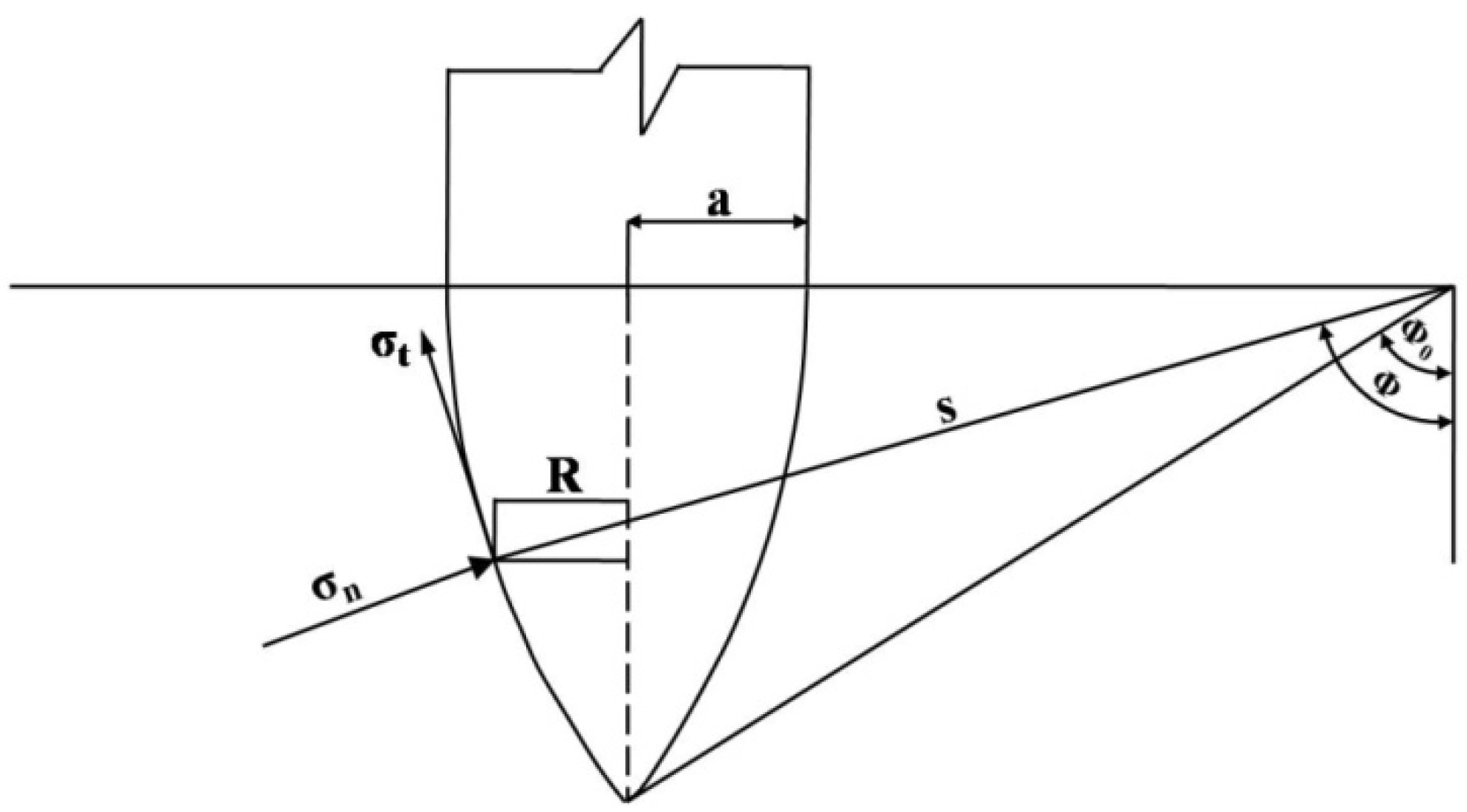
Figure 2.
Soil response regions.
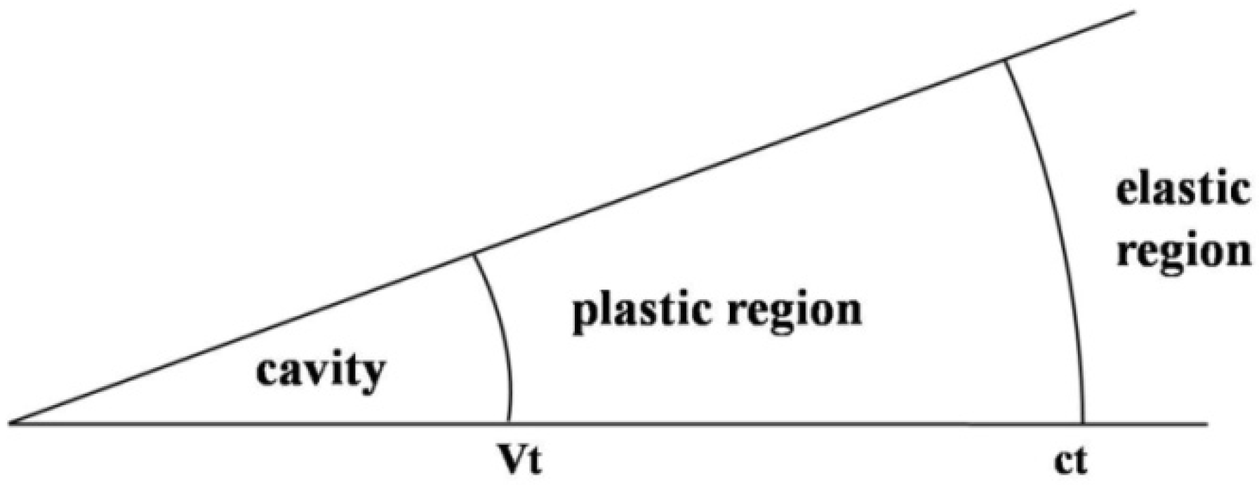
Figure 3.
Particle-size distribution curve of the test sand.
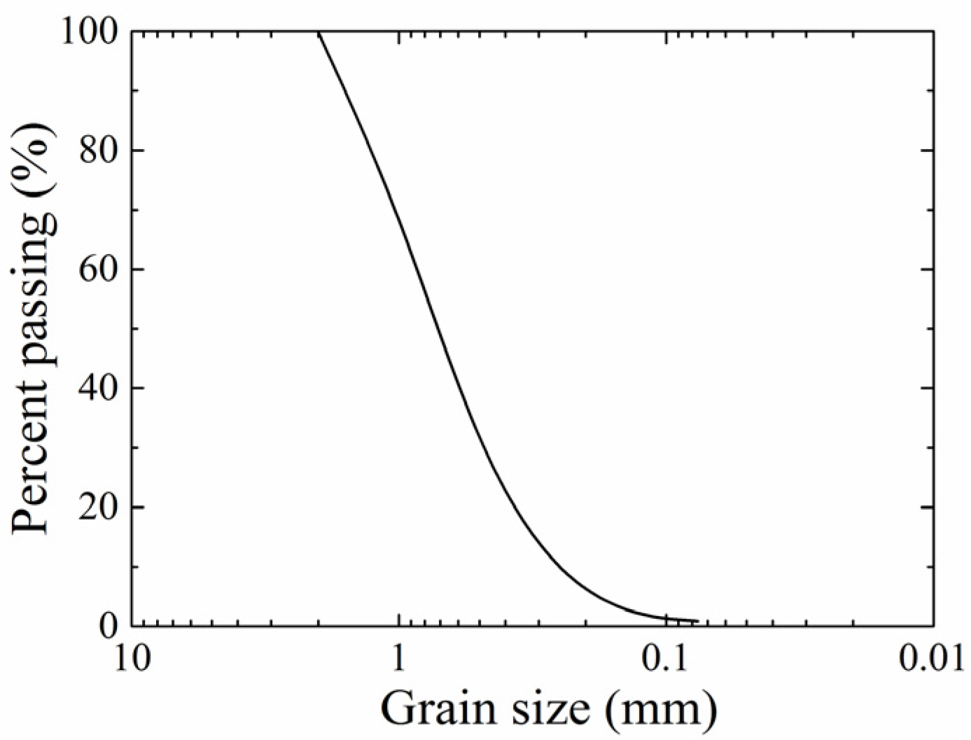
Figure 4.
Schematic of the model test setup (a) layout of penetration test; (b) ejection device; (c) torpedo anchor.
Figure 4.
Schematic of the model test setup (a) layout of penetration test; (b) ejection device; (c) torpedo anchor.
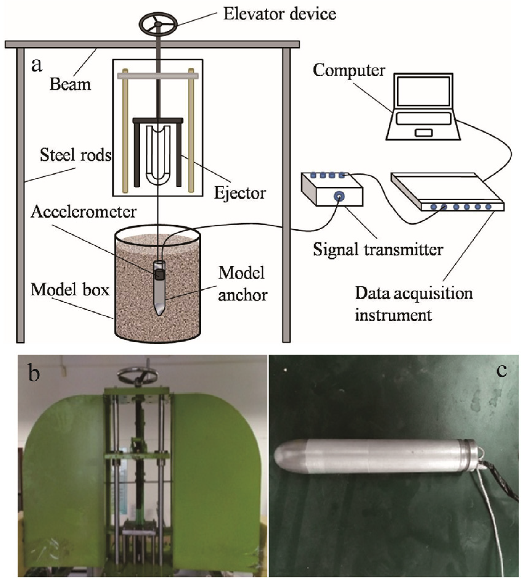
Figure 5.
Curves of depth vs. acceleration (a) Dr = 0.80, V0 = 22.5 m/s; (b) Dr = 0.70, V0 = 23 m/s; (c) Dr = 0.65, V0 = 20.1 m/s; (d) Dr = 0.60, V0 = 20 m/s.
Figure 5.
Curves of depth vs. acceleration (a) Dr = 0.80, V0 = 22.5 m/s; (b) Dr = 0.70, V0 = 23 m/s; (c) Dr = 0.65, V0 = 20.1 m/s; (d) Dr = 0.60, V0 = 20 m/s.
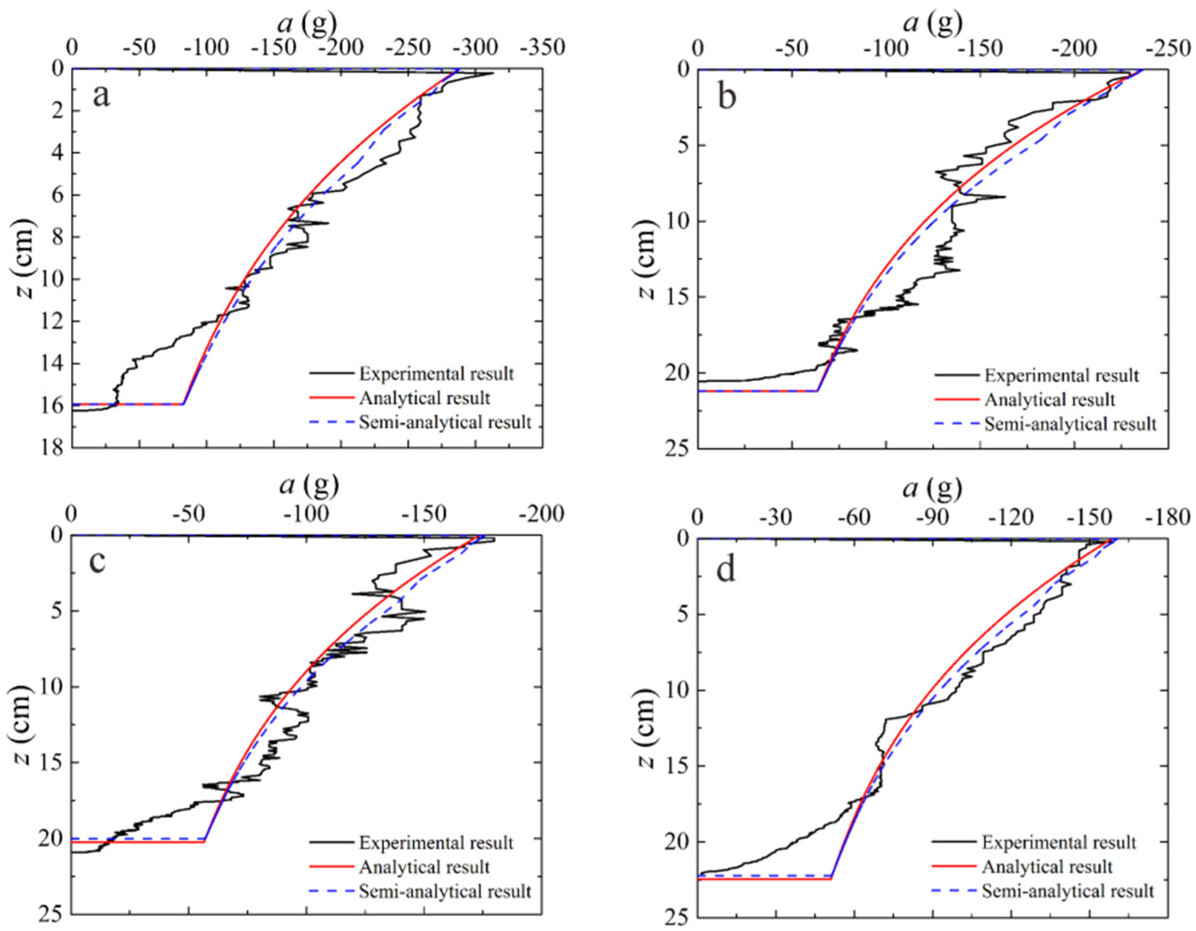
Figure 6.
Curves of depth vs. velocity (a) Dr = 0.80, V0 = 22.5 m/s; (b) Dr = 0.70, V0 = 23 m/s; (c) Dr = 0.65, V0 = 20.1 m/s; (d) Dr = 0.60, V0 = 20 m/s.
Figure 6.
Curves of depth vs. velocity (a) Dr = 0.80, V0 = 22.5 m/s; (b) Dr = 0.70, V0 = 23 m/s; (c) Dr = 0.65, V0 = 20.1 m/s; (d) Dr = 0.60, V0 = 20 m/s.

Table 1.
Strength parameters of saturated sand.
| No. | Dr | τ0/kPa | λ | ρ/(g/cm3) | E/MPa |
|---|---|---|---|---|---|
| A | 0.60 | 22.641 | 1.40 | 1.747 | 100 |
| B | 0.65 | 25.656 | 1.41 | 1.767 | |
| C | 0.70 | 26.094 | 1.43 | 1.789 | |
| D | 0.80 | 31.549 | 1.47 | 1.834 |
Table 2.
Dimensions of the torpedo anchor.
| L/mm | d/mm | m/g | ψ | θ0 |
|---|---|---|---|---|
| 175 | 25 | 235 | 1.69 | 0.78 |
Table 3.
Comparison of final penetration depths.
| No. | V0/m/s | Z0/cm | Z1/cm | Z2/cm | Z3/cm |
|---|---|---|---|---|---|
| A1 | 16.7 | 12.3 | 12.7 | 11.4 | 11.4 |
| A2 | 20.1 | 14.5 | 14.3 | 14.1 | 14.1 |
| A3 | 22.5 | 16.2 | 16.3 | 15.9 | 15.9 |
| B1 | 16.8 | 16.3 | 16.4 | 16.4 | 16.4 |
| B2 | 20.1 | 18.6 | 18.5 | 18.6 | 18.6 |
| B3 | 23.0 | 20.7 | 20.5 | 21.0 | 21.0 |
| C1 | 16.6 | 16.9 | 17.0 | 16.8 | 16.8 |
| C2 | 20.1 | 20.5 | 20.9 | 20.2 | 20.2 |
| C3 | 22.3 | 21.8 | 21.6 | 22.4 | 22.4 |
| D1 | 16.6 | 18.9 | 18.6 | 18.7 | 18.7 |
| D2 | 20.0 | 22.5 | 22.2 | 22.4 | 22.4 |
| D3 | 22.0 | 24.2 | 24.1 | 24.4 | 24.4 |
Z0 = measured depth; Z1 = penetration depth obtained by integrating the measured acceleration curve; Z2 = semi-analytical solution of penetration depth; Z3 = analytical solution of penetration depth.
Publisher’s Note: MDPI stays neutral with regard to jurisdictional claims in published maps and institutional affiliations. |
© 2022 by the authors. Licensee MDPI, Basel, Switzerland. This article is an open access article distributed under the terms and conditions of the Creative Commons Attribution (CC BY) license (https://creativecommons.org/licenses/by/4.0/).
Share and Cite
MDPI and ACS Style
Li, G.; Zhang, J.; Niu, J.; Liu, J.; Yang, Y. Dynamic Penetration Process of Torpedo Anchors into Sand Foundation. J. Mar. Sci. Eng. 2022, 10, 1097. https://doi.org/10.3390/jmse10081097
AMA Style
Li G, Zhang J, Niu J, Liu J, Yang Y. Dynamic Penetration Process of Torpedo Anchors into Sand Foundation. Journal of Marine Science and Engineering. 2022; 10(8):1097. https://doi.org/10.3390/jmse10081097
Chicago/Turabian StyleLi, Gang, Jinli Zhang, Jinglin Niu, Jia Liu, and Yiran Yang. 2022. "Dynamic Penetration Process of Torpedo Anchors into Sand Foundation" Journal of Marine Science and Engineering 10, no. 8: 1097. https://doi.org/10.3390/jmse10081097
Note that from the first issue of 2016, this journal uses article numbers instead of page numbers. See further details here.