
SASD Modeling Using an ANFIS to Prevent the Collision of MASS in Restricted Areas


Abstract
:1. Introduction
2. Methodology
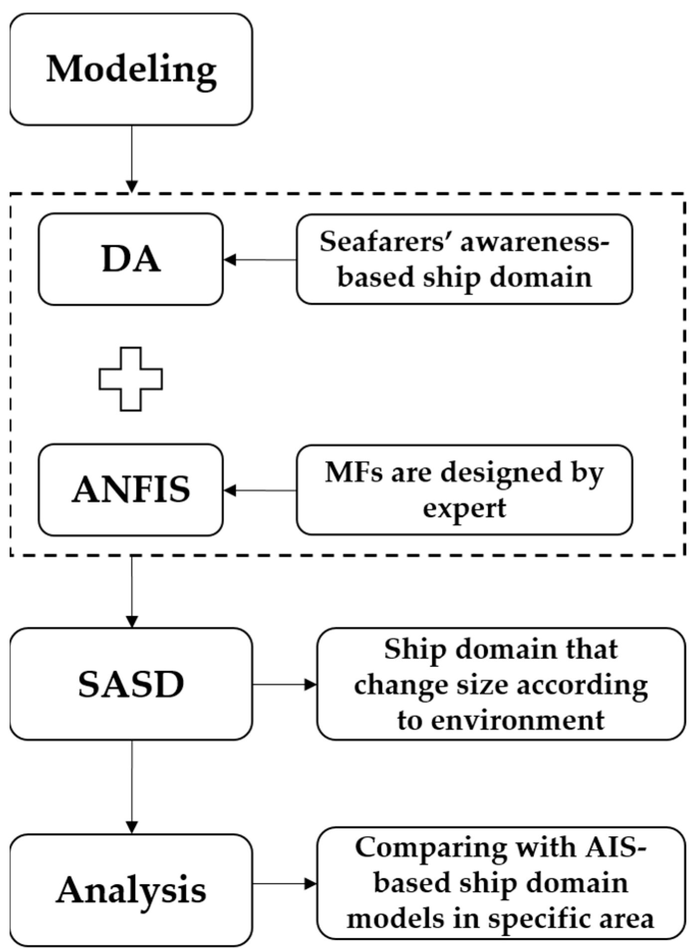
2.1. Overview
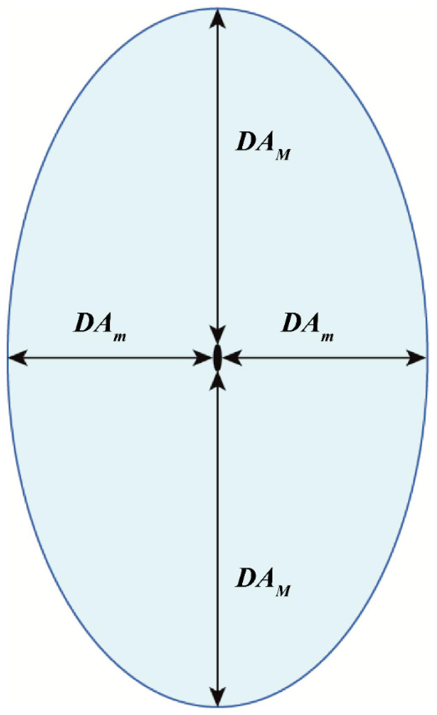
2.2. Domain Based on Awareness
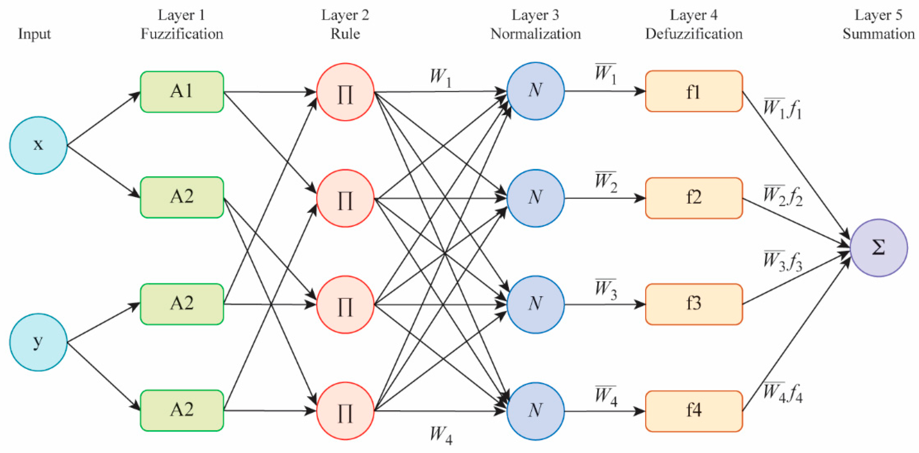
2.3. Configuration of Adaptive Neuro-Fuzzy Inference System
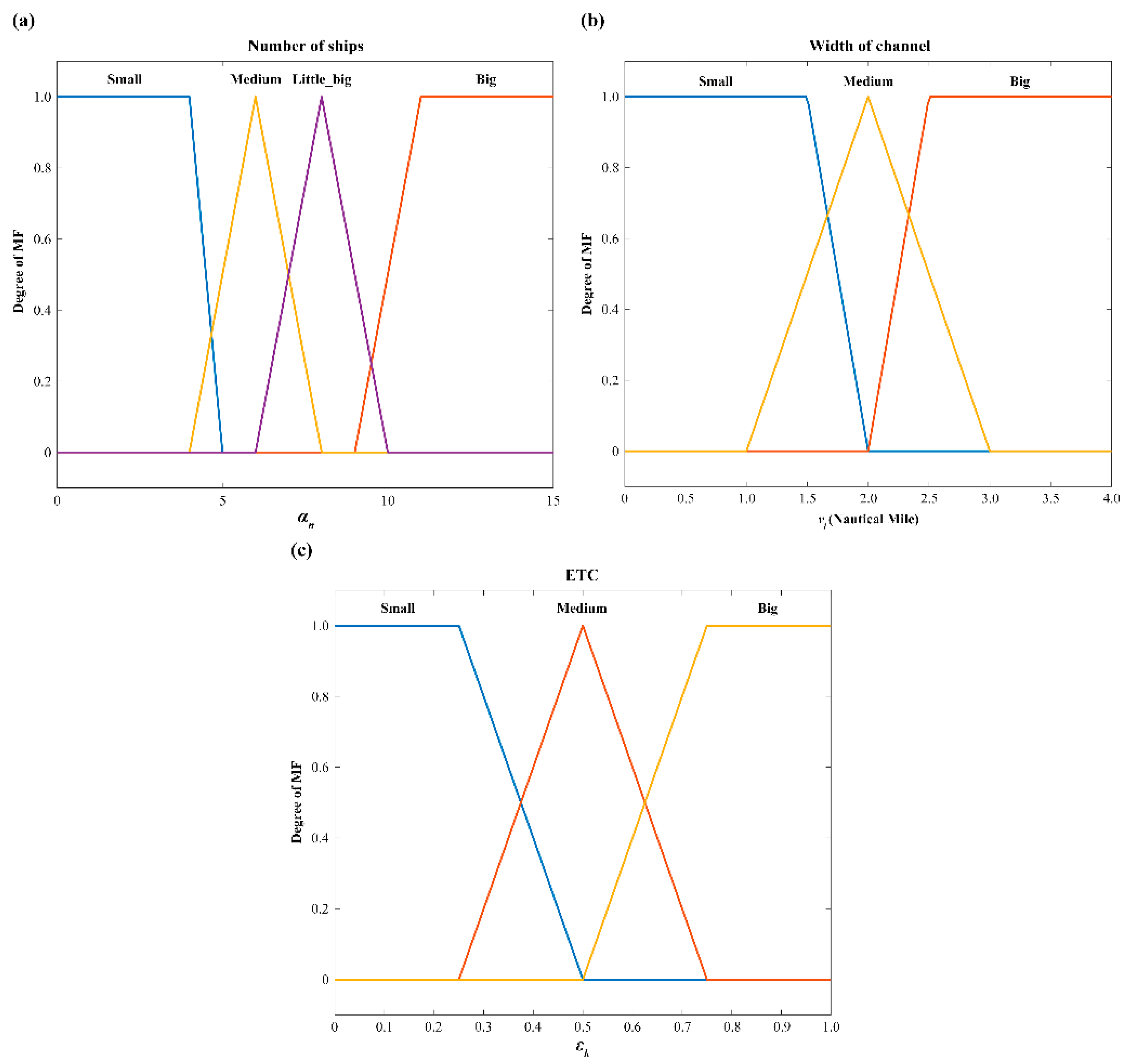
2.4. Reflection Environmental Factors in Restricted Areas for Configuration of the ANFIS
3. Results
3.1. Training Results
3.2. Seafarers’ Awareness-Based Ship Domain
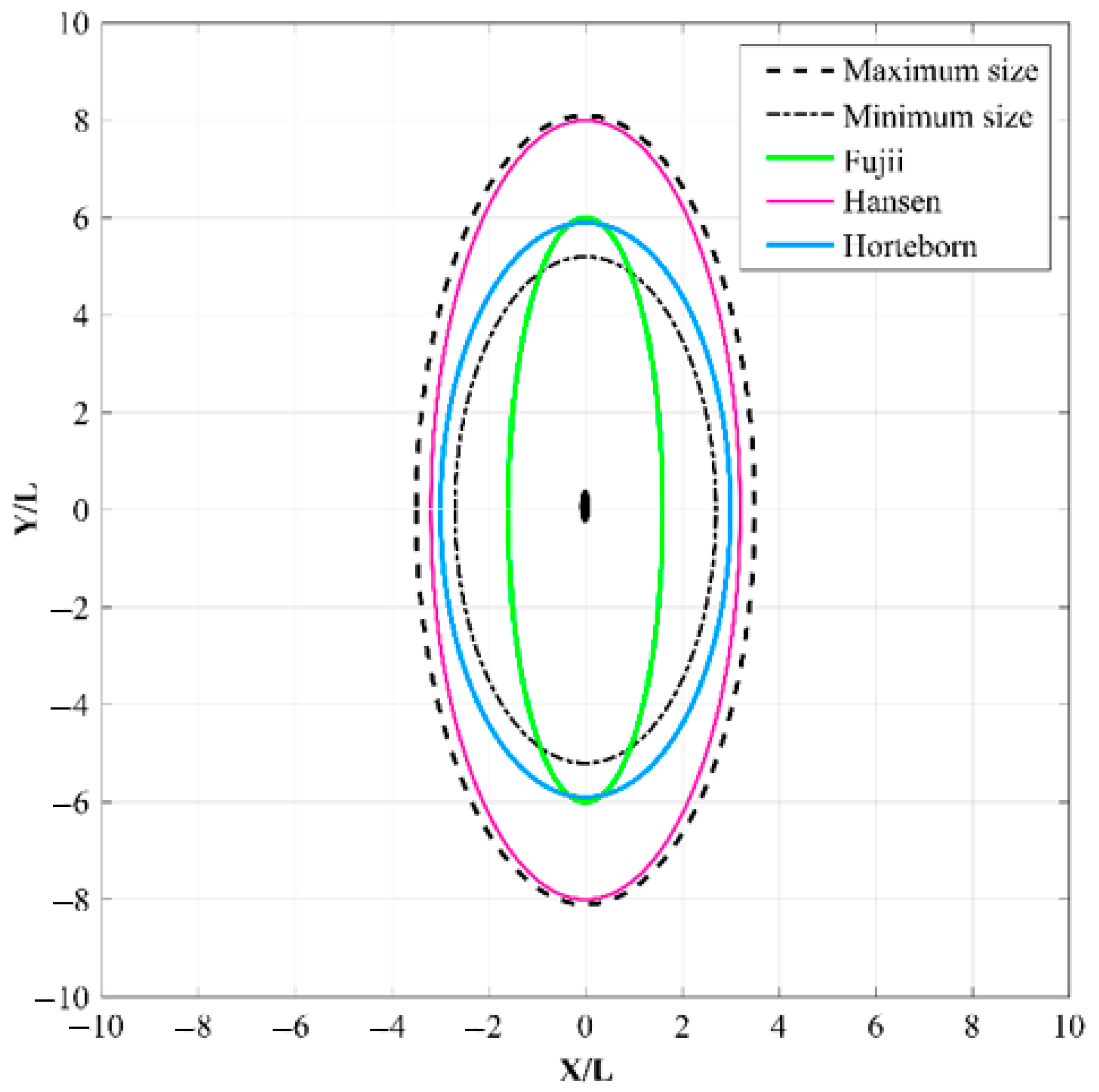
3.3. Comparing Ship Domain Models in a Restricted Area
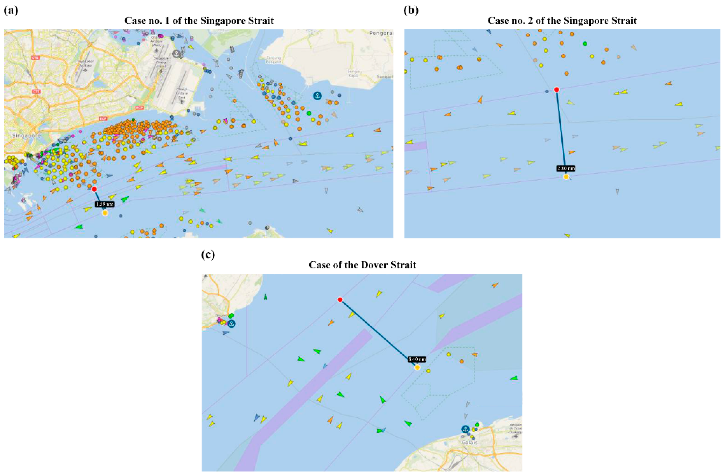
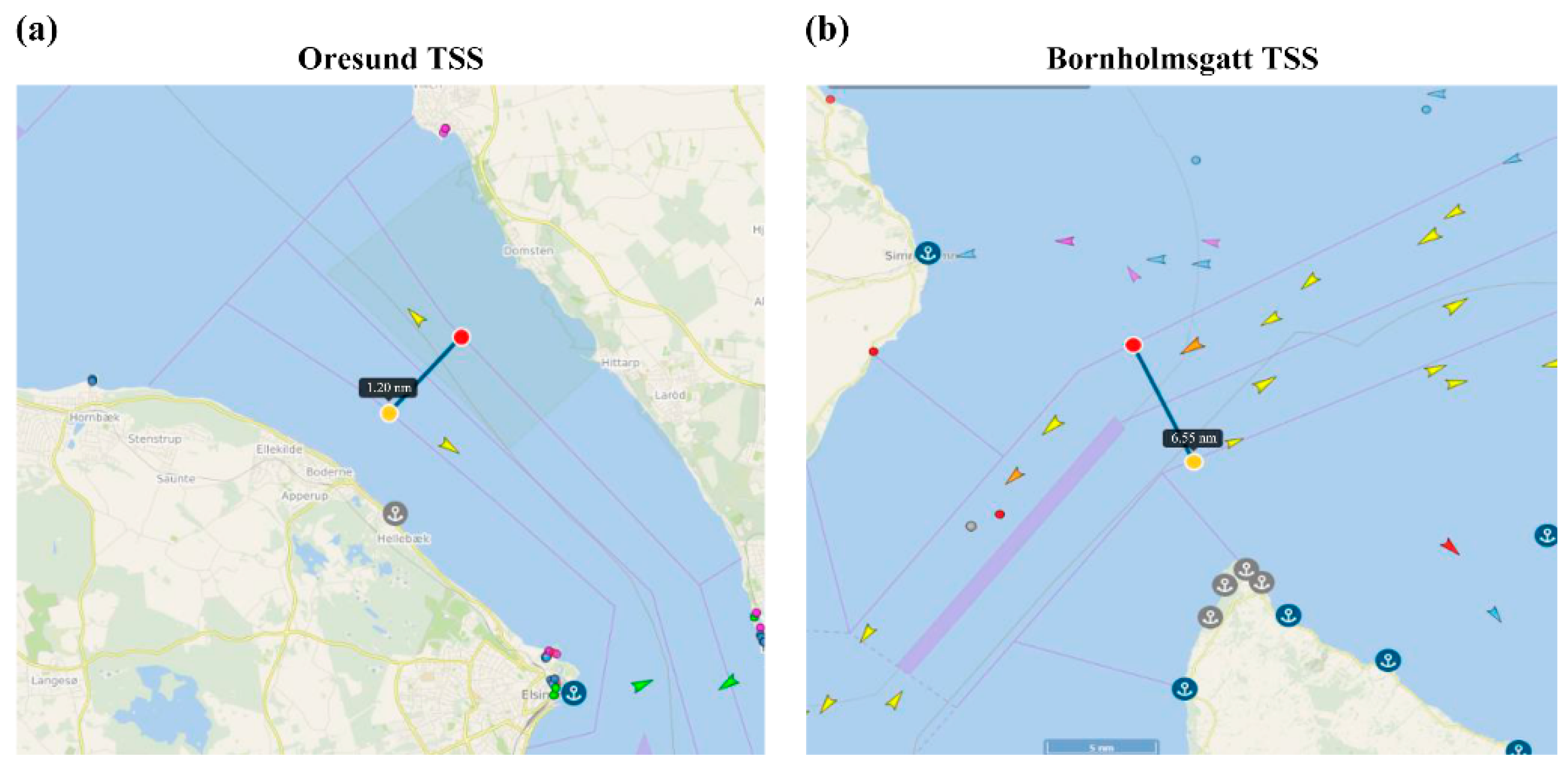
3.4. Application to Restricted Areas
3.4.1. Applying the SASD to Restricted Waters
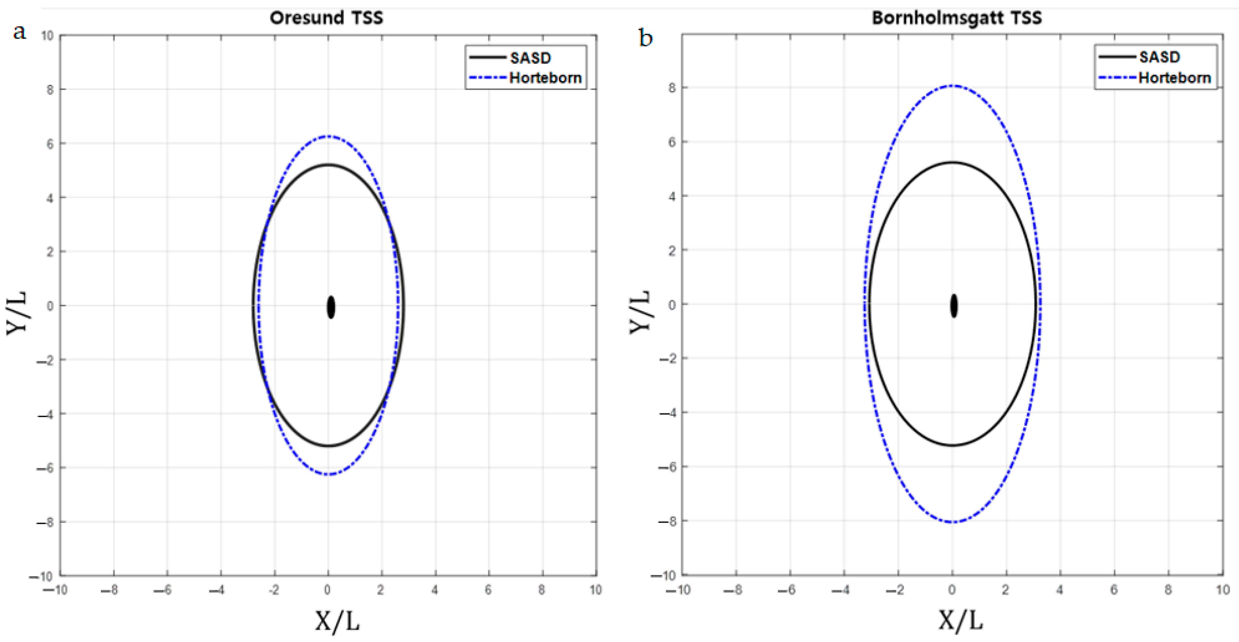
3.4.2. Comparison with the Model of Applied to Specific Waters
4. Discussion
5. Conclusions
Author Contributions
Funding
Institutional Review Board Statement
Informed Consent Statement
Data Availability Statement
Conflicts of Interest
References
- IBM. Mayflower Autonomous Ship Project. 2020. Available online: https://newsroom.ibm.com/2020-03-05-Sea-Trials-Begin-for-Mayflower-Autonomous-Ships-AI-Captain (accessed on 10 June 2021).
- Zaccone, R.; Martelli, M.; Figari, M. A Colreg-Compliant Ship Collision Avoidance Algorithm. In Proceedings of the 2019 18th European Control Conference (ECC), Naples, Italy, 25–28 June 2019; IEEE: Piscataway, NJ, USA, 2019; pp. 2530–2535. [Google Scholar]
- Miyoshi, T.; Fujimoto, S.; Rooks, M.; Konishi, T.; Suzuki, R. Rules required for operating maritime autonomous surface ships from the viewpoint of seafarers. J. Navig. 2022, 75, 384–399. [Google Scholar] [CrossRef]
- Allianz Global Corporate & Speciality. Safety and Shipping Review; Allianz: Munich, Germany, 2021. [Google Scholar]
- EMSA. Annual Overview of Marine Casualties and Incidents 2020; EMSA: Lisbon, Portugal, 2020. [Google Scholar]
- Yim, J.B.; Park, D.J. Estimating Critical Latency Affecting Ship’s Collision in Re-Mote Maneuvering of Autonomous Ships. Appl. Sci. 2021, 11, 10987. [Google Scholar] [CrossRef]
- Gil, M.; Kozioł, P.; Wróbel, K.; Montewka, J. Know your safety indicator–A determination of merchant vessels Bow Crossing Range based on big data analytics. Reliab. Eng. Syst. Saf. 2022, 220, 108311. [Google Scholar] [CrossRef]
- Li, L.; Wu, D.; Huang, Y.; Yuan, Z.M. A path planning strategy unified with a COLREGS collision avoidance function based on deep reinforcement learning and artificial potential field. Appl. Ocean Res. 2021, 113, 102759. [Google Scholar] [CrossRef]
- Vestre, A.; Bakdi, A.; Vanem, E.; Engelhardtsen, Ø. AIS-based near-collision database generation and analysis of real collision avoidance manoeuvres. J. Navig. 2021, 74, 985–1008. [Google Scholar] [CrossRef]
- Szlapczynski, R.; Szlapczynska, J. A ship domain-based model of collision risk for near-miss detection and Collision Alert Systems. Reliab. Eng. Syst. Saf. 2021, 214, 107766. [Google Scholar] [CrossRef]
- Fujii, Y.; Tanaka, K. Traffic capacity. J. Navig. 1971, 24, 543–552. [Google Scholar] [CrossRef]
- Coldwell, T.G. Marine traffic behaviour in restricted waters. J. Navig. 1983, 36, 430–444. [Google Scholar] [CrossRef]
- Davis, P.V.; Dove, M.J.; Stockel, C.T. A computer simulation of multi-ship encounters. J. Navig. 1982, 35, 347–352. [Google Scholar] [CrossRef]
- Goodwin, E.M. A statistical study of ship domains. J. Navig. 1975, 28, 328–344. [Google Scholar] [CrossRef] [Green Version]
- Rawson, A.; Rogers, E.; Foster, D.; Phillips, D. Practical application of domain analysis: Port of London case study. J. Navig. 2014, 67, 193–209. [Google Scholar] [CrossRef]
- Szlapczynski, R.; Krata, P.; Szlapczynska, J. Ship domain applied to determining distances for collision avoidance manoeuvres in give-way situations. Ocean Eng. 2018, 165, 43–54. [Google Scholar] [CrossRef]
- Yim, J.B.; Park, D.J. Modelling Evasive Actions to Be Implemented at the Minimum Distance for Collision Avoidance in a Give-Way Situation. Ocean Eng. 2022; underwork. [Google Scholar]
- Bakdi, A.; Vanem, E. Fullest COLREGs Evaluation Using Fuzzy Logic for Collaborative Decision-Making Analysis of Autonomous Ships in Complex Situations. IEEE Trans. Intell. Trans. Syst. 2022, 1–13. [Google Scholar] [CrossRef]
- Szlapczynski, R.; Szlapczynska, J. Review of ship safety domains: Models and applications. Ocean Eng. 2017, 145, 277–289. [Google Scholar] [CrossRef]
- Wang, Y.; Chin, H.C. An empirically-calibrated ship domain as a safety criterion for navigation in confined waters. J. Navig. 2016, 69, 257–276. [Google Scholar] [CrossRef] [Green Version]
- Gucma, L.; Marcjan, K. Examination of ships passing distances distribution in the coastal waters in order to build a ship probabilistic domain. Zesz. Nauk./Akad. Morska W Szczec. 2012, 32, 34–40. [Google Scholar]
- Hansen, M.G.; Jensen, T.K.; Lehn-Schiøler, T.; Melchild, K.; Rasmussen, F.M.; Ennemark, F. Empirical ship domain based on AIS data. J. Navig. 2013, 66, 931–940. [Google Scholar] [CrossRef] [Green Version]
- Iperen, W.H. Classifying ship encounters to monitor traffic safety on the North Sea from AIS data. TransNav Int. J. Mar. Navig. Saf. Sea Trans. 2015, 9, 51–58. [Google Scholar] [CrossRef] [Green Version]
- Hörteborn, A.; Ringsberg, J.W.; Svanberg, M.; Holm, H. A revisit of the definition of the ship domain based on AIS analysis. J. Navig. 2019, 72, 777–794. [Google Scholar] [CrossRef]
- Kijima, K.; Furukawa, Y. Automatic collision avoidance system using the concept of blocking area. IFAC Proc. Vol. 2003, 36, 223–228. [Google Scholar] [CrossRef]
- Liu, J.; Zhou, F.; Li, Z.; Wang, M.; Liu, R.W. Dynamic ship domain models for capacity analysis of restricted water channels. J. Navig. 2016, 69, 481–503. [Google Scholar] [CrossRef] [Green Version]
- Wang, N. A novel analytical framework for dynamic quaternion ship domains. J. Navig. 2013, 66, 265–281. [Google Scholar] [CrossRef] [Green Version]
- Jingsong, Z.; Zhaolin, W.; Fengchen, W. Comments on ship domains. J. Navig. 1993, 46, 422–436. [Google Scholar] [CrossRef]
- Lee, H.J.; Furukawa, Y.; Park, D.J. Seafarers’ awareness-based domain modelling in restricted areas. J. Navig. 2021, 74, 1172–1188. [Google Scholar] [CrossRef]
- Hsu, F.H. IBM’s deep blue chess grandmaster chips. IEEE Micro 1999, 19, 70–81. [Google Scholar]
- Wang, F.Y.; Zhang, J.J.; Zheng, X.; Wang, X.; Yuan, Y.; Dai, X.; Yang, L. Where does AlphaGo go: From church-turing thesis to AlphaGo thesis and beyond. IEEE/CAA J. Automat. Sin. 2016, 3, 113–120. [Google Scholar]
- Qiao, Z.; Zhang, Y.; Wang, S. A Collision Risk Identification Method for Autonomous Ships Based on Field Theory. IEEE Access 2021, 9, 30539–30550. [Google Scholar] [CrossRef]
- Karaboga, D.; Kaya, E. Adaptive network based fuzzy inference system (ANFIS) training approaches: A comprehensive survey. Artif. Intell. Rev. 2019, 52, 2263–2293. [Google Scholar] [CrossRef]
- Ali, M.; Ghatol, A. A Neuro-Fuzzy Inference System for Student Modeling in Web-Based Intelligent Tutoring Systems. In Proceedings of the International Conference on Cognitive Systems, Victoria, BC, Canada, 11 December 2004. [Google Scholar]
- Kurnaz, S.; Cetin, O.; Kaynak, O. Adaptive neuro-fuzzy inference system based autonomous flight control of unmanned air vehicles. Expert Syst. Appl. 2010, 37, 1229–1234. [Google Scholar] [CrossRef]
- Karaboğa, D.; Kaya, E. Evaluation of Performance of Adaptive and Hybrid abc (aabc) Algorithm in Solution of Numerical Optimization Problems. In Proceedings of the Intelligent Systems and Applications Conference (ASYU), Adana, Turkey, 4–6 October 2018; IEEE: Piscataway, NJ, USA, 2018; pp. 1–5. [Google Scholar]
- Zadeh, L.A. Fuzzy logic. Scholarpedia 2008, 3, 1766. [Google Scholar] [CrossRef]
- Jang, J.S. ANFIS: Adaptive-network-based fuzzy inference system. IEEE Trans. Syst. Man Cybern. 1993, 23, 665–685. [Google Scholar] [CrossRef]
- Kosko, B. Fuzzy Associative Memory Systems. In Fuzzy Expert Systems; CRC Press: Boca Raton, FL, USA, 1992; pp. 135–162. [Google Scholar]
- Kar, S.; Das, S.; Ghosh, P.K. Applications of neuro fuzzy systems: A brief review and future outline. Appl. Soft Comput. 2014, 15, 243–259. [Google Scholar] [CrossRef]
- Ahn, J.H.; Rhee, K.P.; You, Y.J. A study on the collision avoidance of a ship using neural networks and fuzzy logic. Appl. Ocean Res. 2012, 37, 162–173. [Google Scholar] [CrossRef]
- Sedova, N.A.; Sedov, V.A.; Bazhenov, R.I. The neural-fuzzy approach as a way of preventing a maritime vessel accident in a heavy traffic zone. Adv. Fuzzy Syst. 2018, 2018, 2367096. [Google Scholar] [CrossRef] [Green Version]
- Namgung, H.; Kim, J.S. Collision risk inference system for maritime autonomous surface ships using COLREGs rules compliant collision avoidance. IEEE Access 2021, 9, 7823–7835. [Google Scholar] [CrossRef]
- Inoue, K. Evaluation method of ship-handling difficulty for navigation in restricted and congested waterways. J. Navig. 2000, 53, 167–180. [Google Scholar] [CrossRef]
- Endsley, M.R. Design and evaluation for situation awareness enhancement. Proc. Hum. 1988, 32, 97–101. [Google Scholar] [CrossRef]
- MATLAB. MATLAB and Statistical Toolbox; Release 2021a; Math Works Inc.: Natick, MA, USA, 2021. [Google Scholar]
- Vesselfinder. 2022. Available online: http://www.vesselfinder.com (accessed on 10 June 2021).


| Rank | Career | 1st Priority | 2nd Priority |
|---|---|---|---|
| C/O | 13 | Volume of Traffic | Size of TS |
| C/O | 18 | Volume of Traffic | Width of channel |
| C/O | 13 | Volume of Traffic | Size of TS |
| C/O | 14 | Size of TS | Volume of Traffic |
| C/O | 13 | Width of channel | Volume of Traffic |
| Captain | 16 | Size of TS | Volume of Traffic |
| Captain | 19 | Volume of Traffic | Width of channel |
| Captain | 30 | Volume of Traffic | Current |
| Captain | 14 | Irregular situation | Fishing boat |
| Captain | 14 | Width of channel | Current |
| Pilot | 34 | Volume of Traffic | Width of channel |
| Current | Fishing Boat | Size of TS | |
|---|---|---|---|
| Big | More than 3 kts | More than 10 | More than 250 m |
| Medium | 1~3 kts | 5~10 | 150~250 m |
| Small | Less than 1 kts | Less than 5 | Less than 150 m |
| Train | 0.16 L | 0.08 L |
| Test | 0.15 L | 0.09 L |
| Validation | 0.18 L | 0.08 L |
Publisher’s Note: MDPI stays neutral with regard to jurisdictional claims in published maps and institutional affiliations. |
© 2022 by the authors. Licensee MDPI, Basel, Switzerland. This article is an open access article distributed under the terms and conditions of the Creative Commons Attribution (CC BY) license (https://creativecommons.org/licenses/by/4.0/).
Share and Cite
Lee, H.-J.; Park, D.-J. SASD Modeling Using an ANFIS to Prevent the Collision of MASS in Restricted Areas. J. Mar. Sci. Eng. 2022, 10, 961. https://doi.org/10.3390/jmse10070961
Lee H-J, Park D-J. SASD Modeling Using an ANFIS to Prevent the Collision of MASS in Restricted Areas. Journal of Marine Science and Engineering. 2022; 10(7):961. https://doi.org/10.3390/jmse10070961
Chicago/Turabian StyleLee, Hee-Jin, and Deuk-Jin Park. 2022. "SASD Modeling Using an ANFIS to Prevent the Collision of MASS in Restricted Areas" Journal of Marine Science and Engineering 10, no. 7: 961. https://doi.org/10.3390/jmse10070961
APA StyleLee, H.-J., & Park, D.-J. (2022). SASD Modeling Using an ANFIS to Prevent the Collision of MASS in Restricted Areas. Journal of Marine Science and Engineering, 10(7), 961. https://doi.org/10.3390/jmse10070961