Article

Prediction of the Deterioration of FRP Composite Properties Induced by Marine Environments

Marine Engineering Department, Faculty of Maritime Studies, University of Rijeka, Studentska 2, HR-51000 Rijeka, Croatia
*
Author to whom correspondence should be addressed.
J. Mar. Sci. Eng. 2022, 10(4), 510; https://doi.org/10.3390/jmse10040510
Submission received: 7 March 2022 / Revised: 31 March 2022 / Accepted: 4 April 2022 / Published: 6 April 2022
(This article belongs to the Section Marine Environmental Science)

Abstract

:
In this paper, a model for the prediction of fatigue life degradation of fiber-reinforced (FRP) composite materials exposed for prolonged periods to real marine environments is proposed. The data collected during the previous phases of a more comprehensive research of real marine environment-induced changes of mechanical properties in FRP composites are used to assess the influence of these changes on the durability characteristics of composites. Attention is paid to the classification societies’ design and exploitation rules on this matter. The need for the modification of the process used for obtaining composite material S–N curves, considering the influence of the marine environment, is studied. A regression analysis of the experimental data is conducted, resulting in a mathematical model of strength degradation over time. The regression analysis shows an acceptable correlation value. The S–N curves for E-glass/polyester composites with three different fiber layout configurations are evaluated and modified to encompass the findings of this research.

1. Introduction

The use of fiber-reinforced polymer (FRP) composites is becoming increasingly accepted in almost every industry sector, either for entire structures [1,2] or in combination with other, so-called traditional materials [3,4,5]. The marine industry sector is no exception to this trend [6], as FRP composites are finding application in the transportation industry, especially in the maritime sector, whether it be in the construction of lightweight ship structures [7,8] or other marine structures [9,10].
A number of studies carried out in this field over the last couple of decades have aimed to consolidate the experimental and scientific knowledge obtained so far with the goal of developing prediction models that can be used to achieve the sustainable and safe design of engineering structures [11,12,13,14]. It is likely that the most important advantage of composite materials is their adaptability to specific application demands by defining layup sequences, the number of plies, and the fiber orientation in the principal loading directions [15,16,17]. Such flexibility in application makes FRP composites increasingly appealing to engineers when designing marine structures of complex shapes. As the application field for marine composites widens, the request for mechanical and environmental resilience rises. Limit stress states, durability and life span, failure modes, fracture toughness, fire resistance, and environment influence parameters are crucial for an efficient, sustainable, and secure design process for structures in this demanding industry sector [18,19,20,21].
In practice, marine structural designers tend to avoid the micromechanics of composites as they can be too convoluted and tedious for everyday use, resulting in them ignoring this aspect in the design process and turning to rules and procedures which can be conservative, empirical, and not completely encompass all the specificities of newly emerging materials such as FRP composites. The design results are consequently often not optimal for failure modeling. It is up to the scientists in this field of study to define, develop, and produce simple engineering tools to improve the design process.
The dominating methods used for composite failure data collection are experiment-based. The main downside of these methods is the cost and time needed for such experiments if all aspects of real marine environments are to be taken into consideration. The dominant parameters influencing the mechanical properties of composite materials in marine applications are the absorption of seawater [22,23] and the negative effects of polluted process waters from ship systems to constructive materials [24].
The prevailing composite chosen as a construction material in the civil sector of the marine industry for both commercial and small-hull vessels is glass fiber-reinforced plastics [25]. This choice is the result of the favorable material characteristics, yielding a more cost-effective product. The strict rules, standards, and recommended practices of the classification societies restrict the choice of matrix and fiber materials used in marine structures to E-glass or carbon fibers and epoxy, polyester, or vinyl-ester resins [26]. The same standard dictates that the effect on the “properties under long term static and cyclic and high rate loads” and the “influence of the environment on properties” must be considered during the design process of marine structures.
The regulations acknowledge that material properties can “change gradually with time and long exposure times” and that significant changes can occur after 1 year but neglect to consider the real marine environment influences. Only the effects of seawater and freshwater are mentioned, with it being stated that freshwater has more severe effects on the composite mechanical properties than seawater. Furthermore, any marine structure is subjected to actions of fouling marine organisms, which is not described in the standards regarding the design of the structure but is considered separately (protection coatings, anti-fouling devices, etc.).
The fatigue of composites immersed in water has been investigated in the past [27,28]. Early research assumed that the absorbed moisture has no influence on the material fatigue strength in sinusoidal tension conditions, with a moisture content no greater than 0.2 percent [29]. However, newer research acknowledges the effects of water absorption on the fatigue strength of composites [30,31]. A phenomenological base fatigue life model of glass fiber-reinforced polymer composite materials has also been proposed [32]. Researchers have also tried to simplify this complex problem to facilitate the engineering application of fatigue life calculations [33].
Some research has taken into account the influence of a protective gel coat on the fatigue of glass polyester composites [34], concluding that polyester content is the only factor determining fatigue strength, while both polyester and gel coat contents have effects on tensile strength. A comprehensive review of S–N curve models for the characterization of composite materials [35] indicated which S–N curve models have the highest fitting capabilities for experimental fatigue data.
Nonetheless, the research presented in this paper aims to encompass the real marine environment effects, including the effects of moving seawater (waves, tidal changes), weather influences, and the impact of the marine organisms that live attached to any typical marine structures. All of these effects are difficult if not impossible to evaluate in laboratory conditions.

2. Materials and Methods

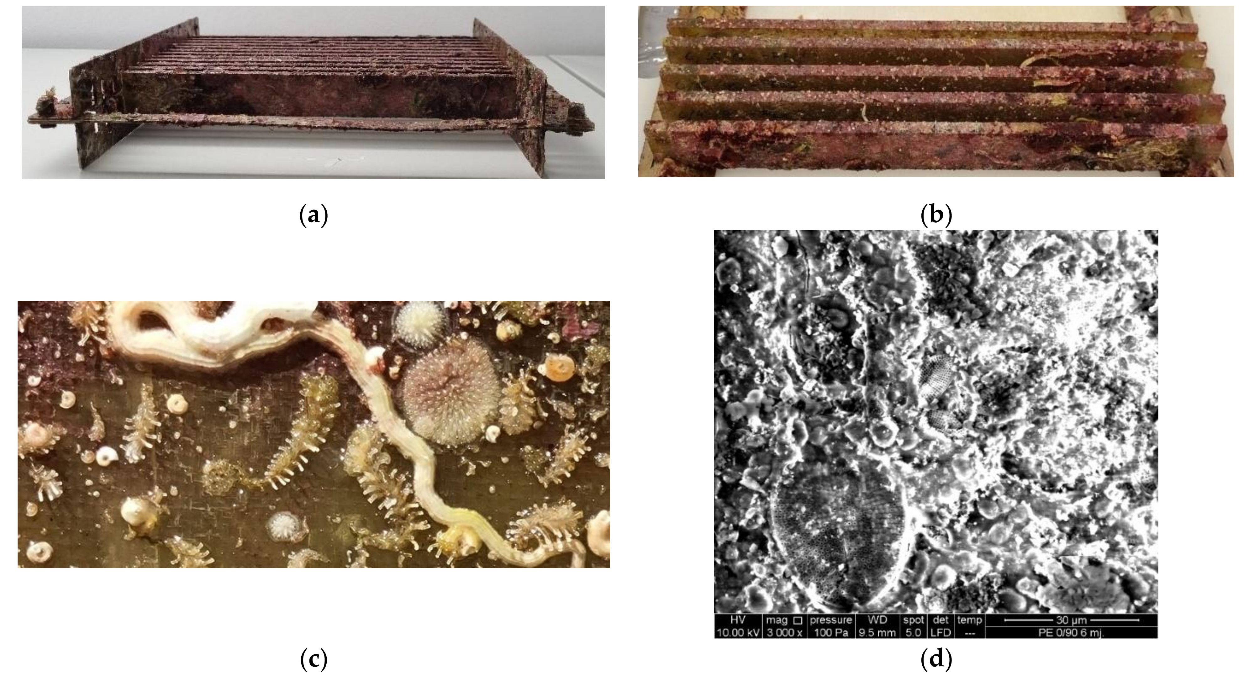
2.1. Experimental Investigation

The analysis of the data collected during the experimental testing phase of this research (250 × 25 × 5 mm coupons, 50 ± 5% fiber reinforcement volume) [21,36] showed the influence of the real sea environment on epoxy/glass and polyester/glass composite materials (with 3 distinct fiber layout configurations—namely, unidirectional UD0°, cross-ply (0/90) s and (0/45/90) s) in the form of reduced mechanical strength for the material submerged in the sea. The marine microorganisms embedded in the resin and invertebrates attached to the surface of the material were identified as a factor that influenced the composite’s mechanical properties. The mechanism (or mechanisms) of the effects that these organisms exert on the material structure needs deeper analysis and research. Nonetheless, the importance of testing in a real marine environment instead of laboratory conditions has become evident. The various marine organisms and microorganisms attached to the coupons are shown in Figure 1.
This research was conducted keeping in mind the inspection and maintenance procedures of marine structures. Eventual damage points that can occur during the exploitation of the hull or any other point of such structures constructed using composites would represent an entry point for seawater. Marine vessels and structures are generally protected by a final gel coat layer or paint that protects them from water penetration. When damage occurs on this protective layer during application, a more significant seawater intake rate in the structure material can be expected. Inspection and maintenance procedures should be planned in a manner that will identify such problematic spots in time to minimize the negative effects of the environment on the structure itself.
The material used in this research was exposed to a real marine environment in the form of standardized coupons [37] for a period of two years, with testing and analysis performed after 6, 12, and 24 months. Most studies concerned with the environmental degradation of the material properties were based on laboratory experiments and either simulated real environments [38] or were conducted in an accelerated manner [39]. Since marine structures need to operate in corrosive environments for long periods, there is a certain gap in research when it comes to experiments that are conducted in the natural environment for prolonged periods [40]. Laboratory results can be useful, but a comprehensive overview can be gained only by studies performed in a natural environment [41]. The parameters evaluated in this study were mass gain due to seawater absorption, dimensional variations, tensile strength changes, and material morphological variations. Special attention was given to the influence of marine organisms on the material strength.

2.2. Numerical Analysis

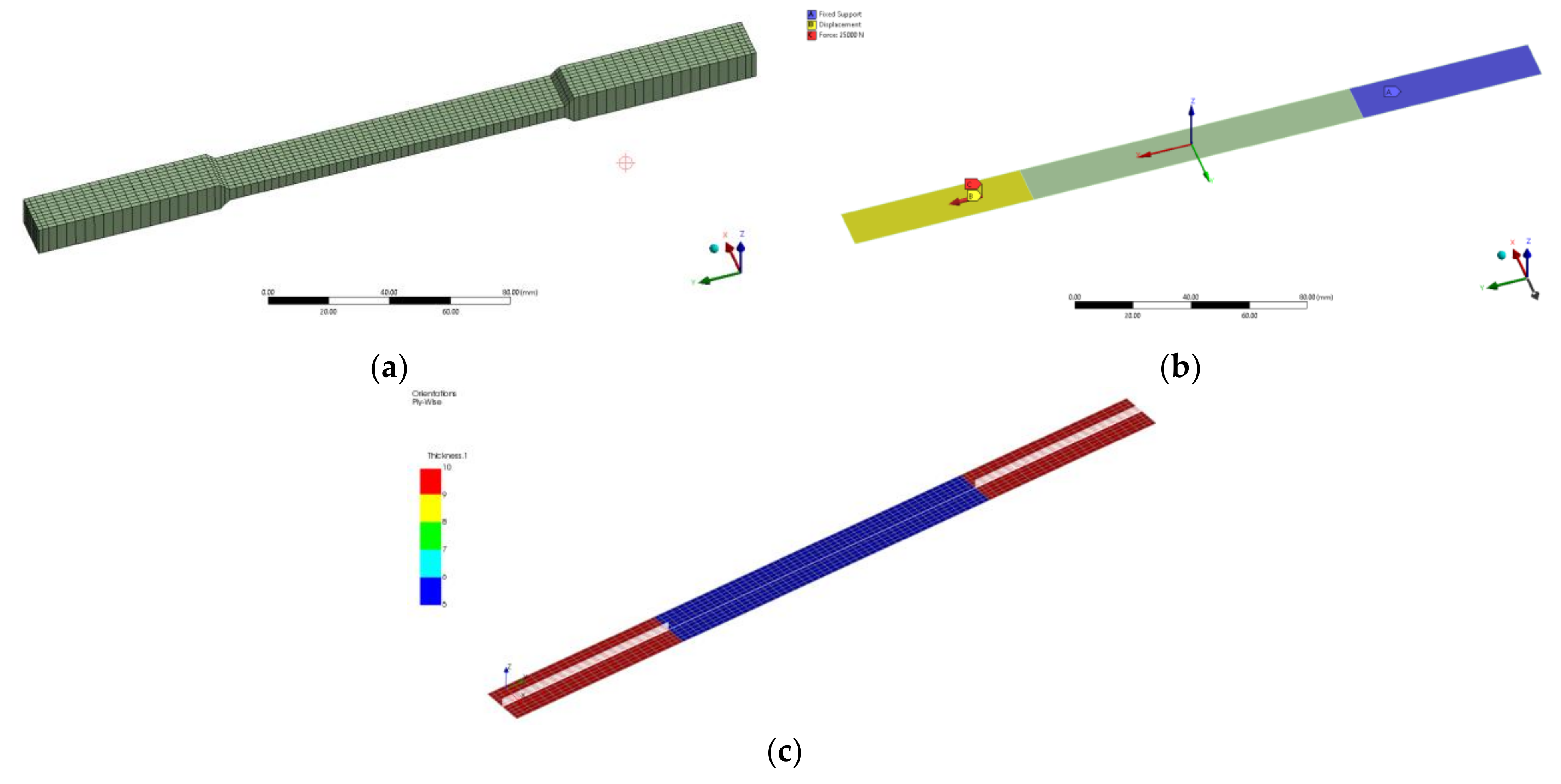
2.2.1. Tensile Test Modelling

The experimental tensile test for dry coupons was modeled in the ANSYS FEA software with the intent to verify the correlation between experimental testing and numerical modeling. The ACP (ANSYS Composite PrepPost) analysis system was used to model the three fiber layout configurations. The FE model was meshed using 4-node shell elements (ANSYS element designation SHELL181), comprising a total of 1034 nodes and 930 elements. The FEA model is shown in Figure 2.
The material characteristics for the polyester resin used were a density of 1200 kg/m3, elasticity modulus of 3240 MPa, effective stress limit of 42 MPa, and Poisson’s ratio of 0.316. The mechanical characteristics of the E-glass fibers were custom specified according to the manufacturer’s specifications: a density of 2000 kg/m3, elasticity modulus of 52.7 GPa in the fiber direction and 10 GPa in the transverse direction, effective tensile stress limit of 573 MPa along the fiber direction and 35 MPa in the transverse direction, shear stress limit of 74 MPa, and Poisson’s ratio of 0.3. The ply type was set as woven. Separate stack-up properties were defined for each fiber layout configuration in the ANSYS ACP tool for the 8-layered coupons and the tabs.
The critical loads were identified ply-wise by the first ply failure (FPF) criteria for each fiber layout configuration.

2.2.2. Regression Analysis

The data collected during a 2-year period were consequently used for a regression analysis to obtain a mathematical model for the strength degradation correlated to the exposure time in the marine environment. The obtained mathematical model was used to predict the loss of strength over a 10-year period.

2.2.3. Structural Durability Assessment

Every marine structure (and/or component) has to pass a certification process prescribed by the regulations in order to prove its safety and functionality up to the end of its design life. A typical expected life period for such structures is from 25 to 40 years. The behavior of the structure in that period is closely related to durability. Much of the research in this field is ongoing and only a small number of marine composite standards reference long-term material properties. The long-term properties of composite materials exposed to the demanding marine environment must be determined in order to integrate the durability issues into the design standards. Current regulations tend to make very conservative assumptions regarding long-term structural behavior, mainly due to a lack of detailed data. For example, the DNV standards [26,42] prescribes the procedure for the identification of critical failure mechanisms and the need for a redesign if necessary. The same standards emphasize the need for a reliable analysis, and, at the same time, the acknowledgement of several uncertainties in loads, materials, and engineering models, consequently referring the designer to component and material testing for long-term data. The marine structure or vessel qualification process requires the identification of static strength, resistance to cyclic fatigue (full fatigue analysis using SN curves at different R-ratios required), stress rupture, damage tolerance, and the effects of the environment on the structure. It is important to mention that if the need for testing arises from the qualification process, static data and long-term data must be measured for the actual product, which further complicates the design process.
The classification societies’ rules prescribe the procedure for obtaining S–N curves for composite materials. Various authors have reported results obtained in modeling S–N curves for composites [29,34,35] and the prediction of the fatigue life of composite structures [27,43,44]. A failure model for groups of similar glass/polyester composites, such as the ones used in this research, can be defined in the form:
log(N) = α(δu/δmax)β,
where N is the number of fatigue life cycles, δu is the ultimate tensile strength (UTS) value, δmax is the maximal tensile stress occurring in the loaded structure, and α and β are experimental data fitting coefficients [44]. Using material data for design purposes obtained previously or by other researchers for similar material types and configurations is acceptable according to the classification societies’ rules.
The loads on marine structures and vessels depend mainly on environmental conditions [45]. The most influential are wave, wind, and water current loads. Ocean waves are predominantly irregular and random in shape, height, length, and speed of propagation. However, for structural design properties, this load can be simplified by deterministic or stochastic methods. In order to determine the quasi-static response of marine structures and vessels, design procedures prescribed by classification societies allow the definition of wave loadings by wavelength and corresponding wave period, wave height, and crest height [46].

3. Results

The results of the experimental investigation of polyester/glass coupons exposed to the marine environment are presented in the form of diagrams, images, and tables in previously published works by the authors of this article. The experimental testing results shown here pertain to the tensile strength determination and surface morphology change observations as a continuation of previous work. A regression analysis was performed on the accumulated data and the results are shown here. A prediction model of fatigue life behavior of the material is proposed.

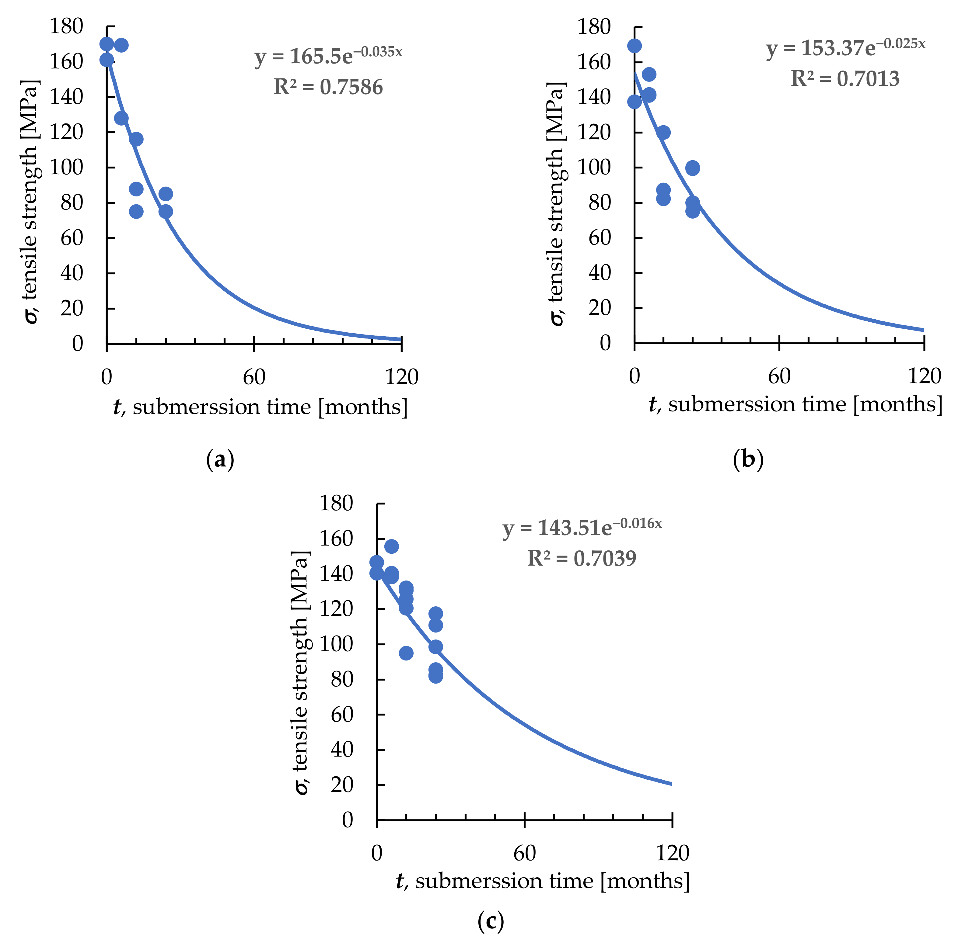
3.1. Regression Analysis Results

Regression results are shown in Figure 3.
The dots represent the experimental data obtained during a 2-year period, whilst the line represents a future forecast of the degradation.
The model of regression that showed the best correlation to experimental data was an exponential equation in the form of:
δu = AeBt,
where δ is the tensile strength value, t is the time of exposure to the marine environment, and A and B are experimental data fitting coefficients. The coefficient A represents the average ultimate tensile stress of the non-submerged specimens tested.
The regression parameters for the three considered fiber layout configurations are given in Table 1.
By combining Equations (1) and (2), a modified S–N curve equation can be obtained in the form:
log(N) = α[(AeBt)/δmax]β,

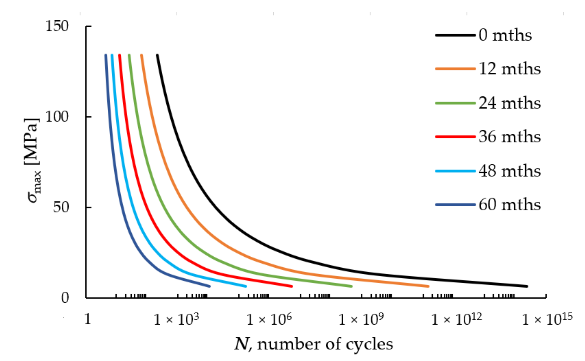
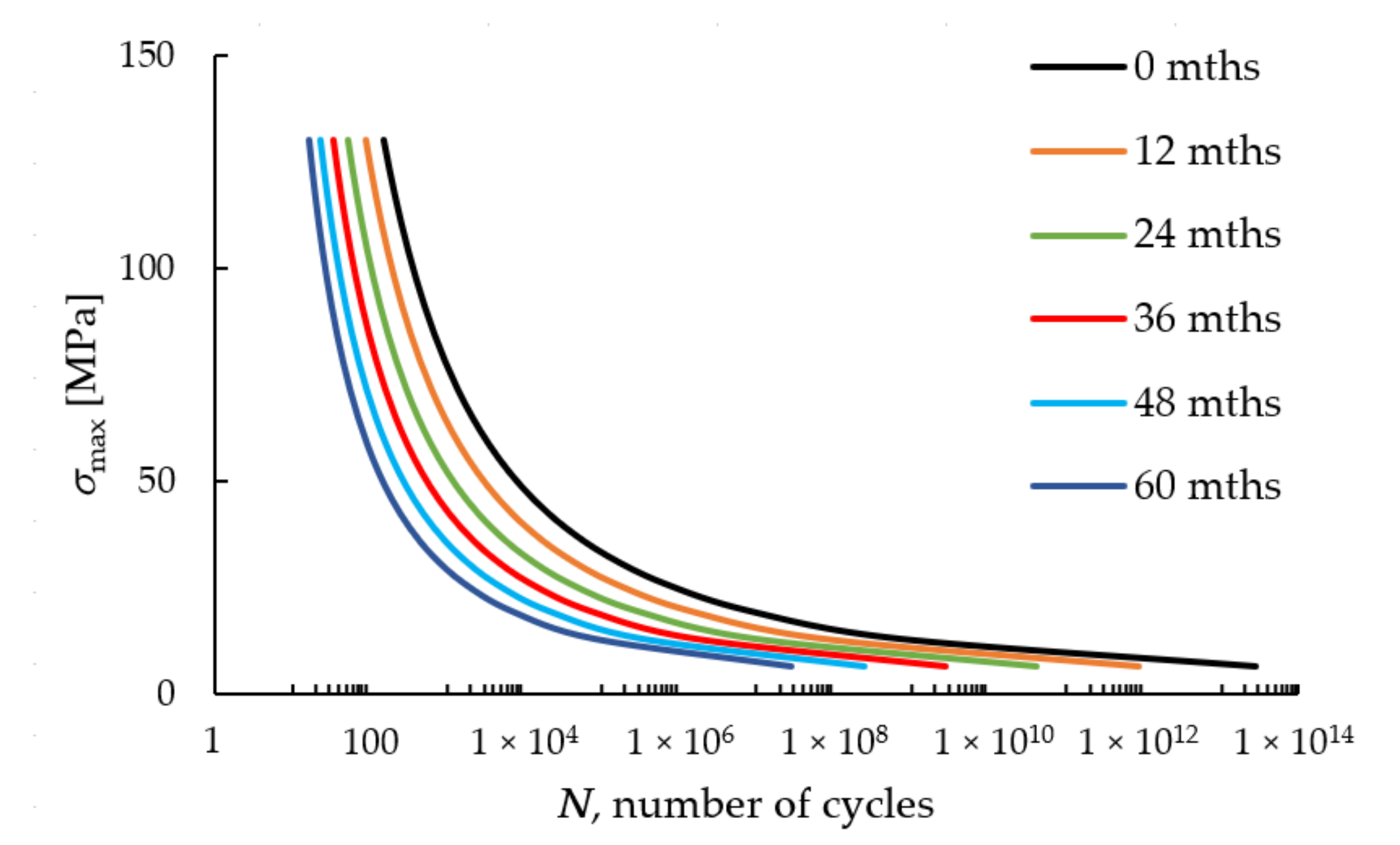
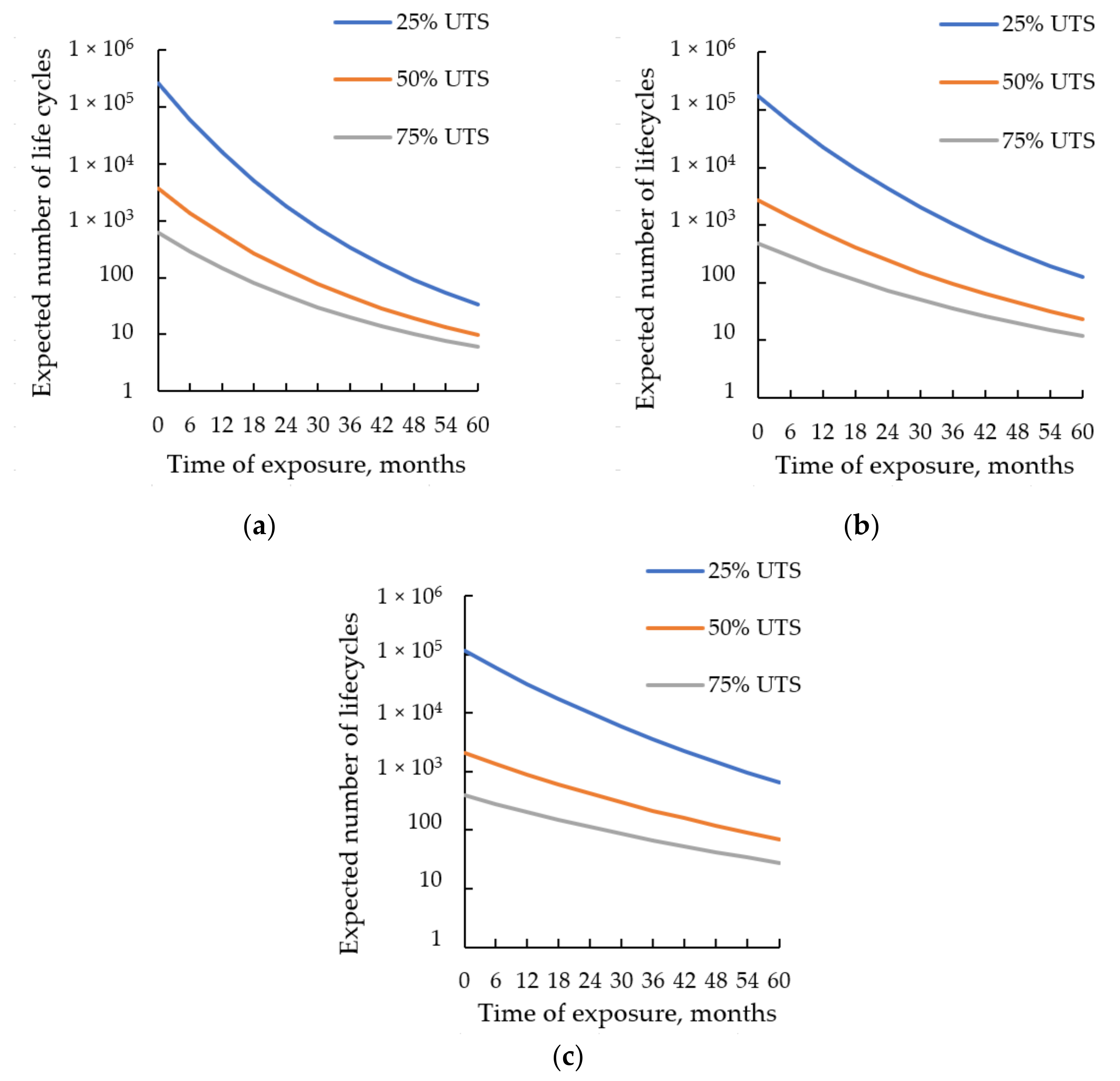
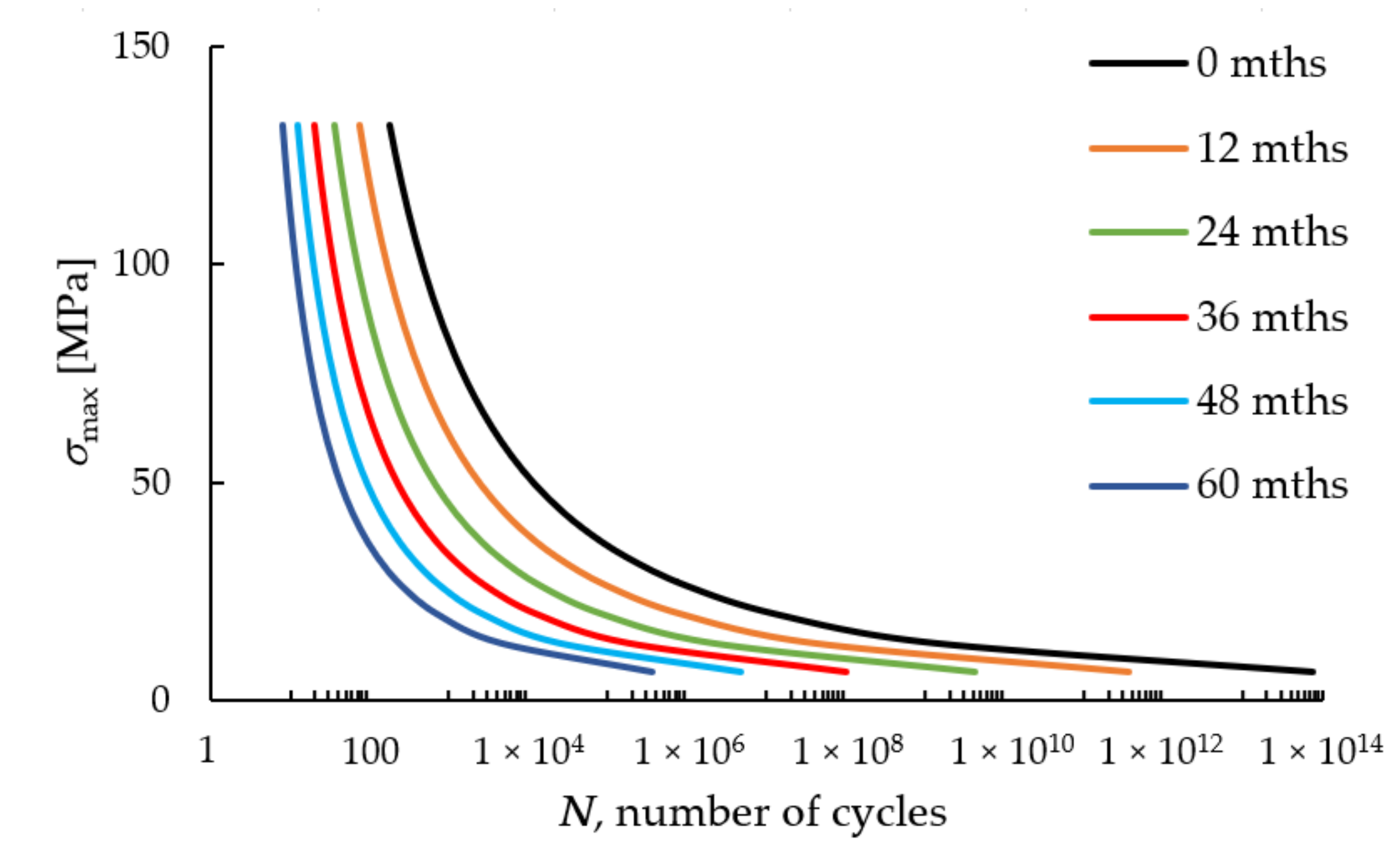
3.2. Prediction of Fatigue Life Behavior

The predicted changes in the S–N curves caused by the change in the ultimate strength value of the unidirectional samples due to the degradation of properties are shown in Figure 4, Figure 5 and Figure 6.
The predicted decrease in expected fatigue life caused by the comprehensive effects of the marine environment is shown in Figure 7.

4. Discussion

The results of the previous research phase conducted by the same authors have shown that the real marine environment has considerable effects on composite materials in the form of reduced mechanical strength after prolonged exposure [21]. Fatigue life decrease intensity has been predicted for all fiber layout configurations with respect to the initial value calculated for dry coupons. The percentage of the strength reduction varies for different fiber layout configurations.
According to the model proposed in this work, after 5 years of exposure to the marine environment, the expected fatigue life decrease (log10 value) for the UD0° coupons is −3.9, −2.6, and −2.0 for 25%, 50%, and 75% UTS, respectively. The other fiber layout configurations exhibited similar behavior—namely, the (0/90) s coupon values are −3.1, −2.1, and −1.6, while for the (0/45/90) s coupons these values are −2.3, −1.5, and −1.2.
This loss of ultimate strength implies that corrections in predicting the fatigue life have to be made considering the period of time for which the material has been submerged in the sea. The value of δu from Equation (1) practically becomes time-dependent. In order to incorporate the variation of ultimate strength, a regression analysis of the tensile test experimental data was performed and a modified S–N curve was obtained.
The actual values of the number of life cycles shown in the Results Section are not to be considered for design purposes, as the curves shown here are normalized to single values of coefficients α and β. These coefficients should be determined experimentally for the actual type of composite material that would be used for a specific structure. The analysis was performed stepwise, meaning that firstly a fatigue life was estimated for reference (dry) coupons not exposed to the sea and then re-estimated for the UTS values after each year.
There is no doubt that additional experimental data both for the 2-year long period of exposure (sea temperature at the location of experiment varies between 10–14 °C annually, salinity changes between 37.8–38.3 PPT, while the pH value is between 8.22–8.29) and longer would refine and raise the accuracy of this prediction model. New research has already been planned to broaden the database for composite material behavior in the marine environment for strength and fatigue structural design aspects. Exposing coupons in various marine environments with different parameters (temperature, salinity, wave, and wind characteristics) would broaden the applicability of this approach as well as increase the models’ validity and accuracy.
Furthermore, as the UTS value continually changes over time, a numerical method should be developed to obtain a continuous degradation S–N curve. This is the aim for further research.
Future work will strive to incorporate the continuous UTS change in the fatigue life decrease model described here and broaden the experimental database in order to develop a more comprehensive predictive numerical model that could successfully replace the time and resource-consuming experiments related to composite material fatigue behavior characterization. The results of this study could prove helpful to determine the composite material type and fiber layout configuration during the engineering design phase of marine vessels and structures. With the acceptance of the importance of the marine environment’s influence on the mechanical behavior of composites and the application of the predictive model for the fatigue life estimation process, the rules and recommendations of classification societies in this industry sector could be amended to improve the design of such structures.

5. Conclusions

The influence of real-time exposure to actual marine environments on the fatigue characteristics of glass/polyester composite materials was investigated in this study, showing the need to incorporate time-decaying ultimate tensile stress in the procedures used for obtaining S–N curves.
As the previous research phases have shown, the changes in the mechanical characteristics of composite materials induced by the actions of both water and marine organisms of the real sea environment were manifested as a reduction in ultimate mechanical strength. For example, the submerged polyester/E-glass UD0°, (0/90) s, and (0/45/90) s coupons lost 11%, 5%, and 1% of their ultimate mechanical strength after 6 months of submersion; 50%, 37%, and 13% of their ultimate mechanical strength after 12 months in the sea; and 55%, 48%, and 24% of their ultimate mechanical strength after 24 months in the water. The results also indicate the dependency of the UTS changes on the fiber layout configurations, with the (0/45/90) s layout showing the greatest resilience to the marine environment. The research up to this phase has made it evident that further study is needed due to two main reasons. Firstly, the polyester coupons were made using the hand-layup process, which can significantly affect the mechanical characteristics of the composite. Secondly, the exact mechanism of marine organisms’ attachment on the surface and marine microorganisms embedding in the resin, as well as the consequences of these phenomena on the mechanical properties of composites exposed to the sea is not known to a satisfactory level. These issues will surely be topics of future research.
Research findings summary:
  • An initial mathematical model of these phenomena was developed based on the experimental data gathered.
  • The loss of ultimate strength required corrections of the procedures used for predicting the fatigue life of composites exposed to the sea.
  • The reduction in ultimate tensile strength for composite materials exposed to the marine environment has a direct influence on the materials’ fatigue behavior.
  • The research results confirmed once again the importance of biofouling in the environmental degradation of the mechanical properties of composite materials in the marine environment.
  • Future work is needed to develop a numerical method to encompass the continuous UTS decay and increase the accuracy of the prediction model.

Author Contributions

Conceptualization, G.V. (Goran Vizentin); methodology, G.V. (Goran Vizentin); formal analysis, G.V. (Goran Vizentin); investigation, G.V. (Goran Vizentin); writing—original draft preparation, G.V. (Goran Vizentin); writing—review and editing, G.V. (Goran Vukelic); visualization, G.V. (Goran Vizentin); supervision, G.V. (Goran Vukelic); project administration, G.V. (Goran Vukelic); funding acquisition, G.V. (Goran Vukelic). All authors have read and agreed to the published version of the manuscript.

Funding

This research was funded by the University of Rijeka, under the project numbers uniri-technic-18-200 “Failure analysis of materials in marine environment” and uniri-technic-18–42 “Investigation, analysis and modeling the behavior of structural elements stressed at room and high temperatures”.

Institutional Review Board Statement

Not applicable.

Informed Consent Statement

Not applicable.

Data Availability Statement

Not applicable.

Conflicts of Interest

The authors declare no conflict of interest. The funders had no role in the design of the study; in the collection, analysis, or interpretation of data; in the writing of the manuscript; or in the decision to publish the results.

References and Notes

  1. Kim, D.-U.; Seo, H.-S.; Jang, H.-Y. Study on Mechanical Bearing Strength and Failure Modes of Composite Materials for Marine Structures. J. Mar. Sci. Eng. 2021, 9, 726. [Google Scholar] [CrossRef]
  2. Wang, C.; Ge, S.; Jaworski, J.W.; Liu, L.; Jia, Z. Effects of Different Design Parameters on the Vortex Induced Vibration of FRP Composite Risers Using Grey Relational Analysis. J. Mar. Sci. Eng. 2019, 7, 231. [Google Scholar] [CrossRef] [Green Version]
  3. Vukelic, G.; Vizentin, G. Composite wrap repair of a failed pressure vessel–Experimental and numerical analysis. Thin-Walled Struct. 2021, 169, 108488. [Google Scholar] [CrossRef]
  4. Vukelic, G.; Vizentin, G.; Bakhtiari, R. Failure analysis of a steel pressure vessel with a composite wrap repair proposal. Int. J. Press. Vessel. Pip. 2021, 193, 104476. [Google Scholar] [CrossRef]
  5. Lukács, J.; Koncsik, Z.; Chován, P. Integrity reconstruction of damaged transporting pipelines applying fiber reinforced polymer composite wraps. Procedia Struct. Integr. 2021, 31, 51–57. [Google Scholar] [CrossRef]
  6. Cejuela, E.; Negro, V.; Del Campo, J.M. Evaluation and Optimization of the Life Cycle in Maritime Works. Sustainability 2020, 12, 4524. [Google Scholar] [CrossRef]
  7. De Ulzurrun, I.D.; López, F.; Herreros, M.; Suárez, J. Tests of deck-to-hull adhesive joints in GFRP boats. Eng. Fail. Anal. 2007, 14, 310–320. [Google Scholar] [CrossRef]
  8. Lee, S.-G.; Oh, D.; Woo, J. The Effect of High Glass Fiber Content and Reinforcement Combination on Pulse-Echo Ultrasonic Measurement of Composite Ship Structures. J. Mar. Sci. Eng. 2021, 9, 379. [Google Scholar] [CrossRef]
  9. Junior, M.W.; Reis, J.; Mattos, H.D.C. Polymer-based composite repair system for severely corroded circumferential welds in steel pipes. Eng. Fail. Anal. 2017, 81, 135–144. [Google Scholar] [CrossRef]
  10. Yang, Z.; Cao, Y.; Liu, J. A Buckling Analysis and Optimization Method for a Variable Stiffness Cylindrical Pressure Shell of AUV. J. Mar. Sci. Eng. 2021, 9, 637. [Google Scholar] [CrossRef]
  11. Durability of Composites in a Marine Environment. In Solid Mechanics and Its Applications; Davies, P.; Rajapakse, Y.D.S. (Eds.) Springer: Dordrecht, The Netherlands, 2014; Volume 208, ISBN 978-94-007-7416-2. [Google Scholar]
  12. Durability of Composites in a Marine Environment 2. In Solid Mechanics and Its Applications; Davies, P.; Rajapakse, Y.D.S. (Eds.) Springer International Publishing: Cham, Switzerland, 2018; Volume 245, ISBN 978-3-319-65144-6. [Google Scholar]
  13. Martin, R. Ageing of Composites; Woodhead Publishing Limited: Cambridge, UK, 2008; ISBN 978-1-84569-352-7. [Google Scholar]
  14. Takacs, L.; Kovacs, L.; Olajos, T. Numerical tool with mean-stress correction for fatigue life estimation of composite plates. Eng. Fail. Anal. 2020, 111, 104456. [Google Scholar] [CrossRef]
  15. Gljušćić, M.; Franulović, M.; Lanc, D.; Božić, Ž. Digital image correlation of additively manufactured CFRTP composite systems in static tensile testing. Procedia Struct. Integr. 2021, 31, 116–121. [Google Scholar] [CrossRef]
  16. Brčić, M.; Kršćanski, S.; Brnić, J. Rotating Bending Fatigue Analysis of Printed Specimens from Assorted Polymer Materials. Polymers 2021, 13, 1020. [Google Scholar] [CrossRef]
  17. Venkatesan, K.; Ramanathan, K.; Vijayanandh, R.; Selvaraj, S.; Kumar, G.R.; Kumar, M.S. Comparative structural analysis of advanced multi-layer composite materials. Mater. Today Proc. 2020, 27, 2673–2687. [Google Scholar] [CrossRef]
  18. Kastratović, G.; Grbović, A.; Sedmak, A.; Božić, Ž.; Sedmak, S. Composite material selection for aircraft structures based on experimental and numerical evaluation of mechanical properties. Procedia Struct. Integr. 2021, 31, 127–133. [Google Scholar] [CrossRef]
  19. Sousa, J.; Marques, J.; Garcia, M.; Infante, V.; Amaral, P. Mechanical characterization of sandwich composites with embedded sensors. Eng. Fail. Anal. 2020, 117, 104765. [Google Scholar] [CrossRef]
  20. Tomasz, M.; Szymon, D.; Bartosz, B.; Joanna, W.; Paweł, Z.; Grzegorz, L. Flexural and compressive residual strength of composite bars subjected to harsh environments. Eng. Fail. Anal. 2022, 133, 105958. [Google Scholar] [CrossRef]
  21. Vizentin, G.; Glujić, D.; Špada, V. Effect of Time-Real Marine Environment Exposure on the Mechanical Behavior of FRP Composites. Sustainability 2021, 13, 9934. [Google Scholar] [CrossRef]
  22. Vizentin, G.; Vukelic, G. Degradation and Damage of Composite Materials in Marine Environment. Mater. Sci. 2019, 26, 337–342. [Google Scholar] [CrossRef] [Green Version]
  23. Tamboura, S.; Abdessalem, A.; Fitoussi, J.; Ben Daly, H.; Tcharkhtchi, A. On the mechanical properties and damage mechanisms of short fibers reinforced composite submitted to hydrothermal aging: Application to sheet molding compound composite. Eng. Fail. Anal. 2022, 131, 105806. [Google Scholar] [CrossRef]
  24. Padmaraj, N.; Vijaya, K.M.; Shreepannaga; Amritha, U.; Dayananda, P. Slurry erosion behaviour of carbon/epoxy quasi-isotropic laminates based on Taguchi’s optimization method. Eng. Fail. Anal. 2021, 123, 105274. [Google Scholar] [CrossRef]
  25. Rubino, F.; Nisticò, A.; Tucci, F.; Carlone, P. Marine Application of Fiber Reinforced Composites: A Review. J. Mar. Sci. Eng. 2020, 8, 26. [Google Scholar] [CrossRef] [Green Version]
  26. DNV-OS-C501 Composite Components. Det Nor. Verit. 2010, 119–134.
  27. Djeghader, D.; Redjel, B. Fatigue of Glass-Polyester Composite Immerged in Water. J. Eng. Sci. Technol. 2017, 12, 1204–1215. [Google Scholar]
  28. Smith, L.V.; Weitsman, Y.J. The immersed fatigue response of polymer composites. Int. J. Fract. 1996, 82, 31–42. [Google Scholar] [CrossRef]
  29. Vázquez, J.; Silvera, A.; Arias, F.; Soria, E. Fatigue properties of a glass-fibre-reinforced polyester material used in wind turbine blades. J. Strain Anal. Eng. Des. 1998, 33, 183–193. [Google Scholar] [CrossRef]
  30. Kennedy, C.R.; Leen, S.B.; Brádaigh, C.M. Ó Immersed Fatigue Performance of Glass Fibre-Reinforced Composites for Tidal Turbine Blade Applications. J. Bio-Tribo-Corrosion 2016, 2, 12. [Google Scholar] [CrossRef] [Green Version]
  31. Gagani, A.I.; Mialon, E.P.; Echtermeyer, A.T. Immersed interlaminar fatigue of glass fiber epoxy composites using the I-beam method. Int. J. Fatigue 2019, 119, 302–310. [Google Scholar] [CrossRef]
  32. Zhang, W.; Zhou, Z.; Zhang, B.; Zhao, S. A phenomenological fatigue life prediction model of glass fiber reinforced polymer composites. Mater. Des. 2015, 66, 77–81. [Google Scholar] [CrossRef]
  33. Mouritz, A.P. A Simple Fatigue Life Model for Three-dimensional Fiber-Polymer Composites. J. Compos. Mater. 2006, 40, 455–469. [Google Scholar] [CrossRef]
  34. Yasar, A.; Kacar, I.; Keskin, A. Tensile and Fatigue Behavior of Glass Fiber-Reinforced (MAT-8)/Polyester Automotive Composite. Arab. J. Sci. Eng. 2014, 39, 3191–3197. [Google Scholar] [CrossRef]
  35. Burhan, I.; Kim, H.S. S-N Curve Models for Composite Materials Characterisation: An Evaluative Review. J. Compos. Sci. 2018, 2, 38. [Google Scholar] [CrossRef] [Green Version]
  36. Vizentin, G.; Vukelic, G. Failure Analysis of FRP Composites Exposed to Real Marine Environment. Procedia Struct. Integr. 2022, 37, 233–240. [Google Scholar] [CrossRef]
  37. International Standard ISO 527; Plastics–Determination of Tensile Properties. ISO: Geneva, Switzerland, 2020.
  38. Choi, Y.Y.; Lee, S.H.; Park, J.-C.; Choi, D.J.; Yoon, Y.S. The impact of corrosion on marine vapour recovery systems by VOC generated from ships. Int. J. Nav. Arch. Ocean Eng. 2019, 11, 52–58. [Google Scholar] [CrossRef]
  39. Kovač, N.; Ivošević, Š.; Vastag, G.; Vukelić, G.; Rudolf, R. Statistical Approach to the Analysis of the Corrosive Behaviour of NiTi Alloys under the Influence of Different Seawater Environments. Appl. Sci. 2021, 11, 8825. [Google Scholar] [CrossRef]
  40. Vukelic, G.; Vizentin, G.; Ivosevic, S. Tensile strength behaviour of steel plates with corrosion-induced geometrical deteriorations. Ships Offshore Struct. 2021, 1–9. [Google Scholar] [CrossRef]
  41. Vukelic, G.; Vizentin, G.; Brnic, J.; Brcic, M.; Sedmak, F. Long-Term Marine Environment Exposure Effect on Butt-Welded Shipbuilding Steel. J. Mar. Sci. Eng. 2021, 9, 491. [Google Scholar] [CrossRef]
  42. DNV GL AS DNVGL-ST-C501 Composite Components; 2017.
  43. Kim, H.; Huang, S. S-N Curve Characterisation for Composite Materials and Prediction of Remaining Fatigue Life Using Damage Function. J. Compos. Sci. 2021, 5, 76. [Google Scholar] [CrossRef]
  44. Silvera, A.; Vàzquez, J.; Vinssac, V. Strain analysis of a glass-fibre-reinforced polyester under dynamic loads. Span. J. Agric. Res. 2011, 9, 49. [Google Scholar] [CrossRef] [Green Version]
  45. DNV Environmental Conditions and Environmental Loads. 2014, p. 182. Available online: http://www.dnv.com (accessed on 28 March 2022).
  46. DNV Wave Loads. 2021, p. 81. Available online: www.dnv.com (accessed on 28 March 2022).
Figure 1. Attached bio-layer: (a) coupons in submerging fixture; (b) coupons after 2 years of submersion; (c) detail of marine organisms attached; (d) scanning electron image of embedded organisms after 6 months of exposure.
Jmse 10 00510 g001
Figure 2. Tensile test FE model: (a) mesh; (b) boundary conditions; (c) ACP layup plot.
Jmse 10 00510 g002
Figure 3. Mathematical strength degradation prediction model: (a) UD0°; (b) (0/90) s; (c) (0/45/90) s fiber layout configuration.
Jmse 10 00510 g003
Figure 4. S–N curve change, UD0° polyester/glass composite.
Jmse 10 00510 g004
Figure 5. S–N curve change, (0/90)s polyester/glass composite.
Jmse 10 00510 g005
Figure 6. S–N curve change, (0/45/90)s polyester/glass composite.
Jmse 10 00510 g006
Figure 7. Normalized (α and β set to a single value) decrease in the expected number of fatigue life cycles, polyester/glass composite: (a) UD0°; (b) (0/90) s; (c) (0/45/90) s fiber layout configuration.
Jmse 10 00510 g007
Table 1. Regression model data.
Fiber Layout ConfigurationCoefficient ACoefficient BR2 Value
UD0°165.50−0.03490.7079
(0/90) s153.37−0.02520.6557
(0/45/90) s143.51−0.01620.6540
Publisher’s Note: MDPI stays neutral with regard to jurisdictional claims in published maps and institutional affiliations.

