Article

Analytical Solutions of Steady a Seepage Field for Deep-Buried Tunnel with Grouting Ring Considering Anisotropic Flow

1
School of Civil Engineering and Architecture, Zhejiang University of Science & Technology, Hangzhou 310023, China
2
School of Engineering, Zhejiang University City College, Hangzhou 310015, China
3
Engineering Research & Development Centre for Underground Technology of Jiangxi Province, East China Jiaotong University, Nanchang 330013, China
4
Research Centre of Coastal and Urban Geotechnical Engineering, Zhejiang University, Hangzhou 310058, China
*
Author to whom correspondence should be addressed.
J. Mar. Sci. Eng. 2022, 10(12), 1861; https://doi.org/10.3390/jmse10121861
Submission received: 31 October 2022 / Revised: 18 November 2022 / Accepted: 20 November 2022 / Published: 2 December 2022
(This article belongs to the Special Issue Advances in Marine Engineering: Geological Environment and Hazards)

Abstract

:
Difficulties related to seepage are frequently encountered in tunnel design and construction, especially in deep-buried tunnels. Nowadays, analytical solutions of steady seepage fields for deep-buried tunnel usually assume that the surrounding rock mass is homogeneous. In this study, analytical solutions of a steady seepage field for a deep-buried tunnel with grouting ring considering anisotropic flow are proposed. The proposed analytical solutions are verified by numerical simulations and parameter analysis are carried out. Results show that the seepage field of surrounding rocks around the deep buried circular tunnel is no longer uniformly distributed and presents elliptical distribution. The change of permeability coefficient of the lining structure has a great influence on the hydraulic head when the difference between permeability coefficient of lining structure and surrounding rock is not very large. The results show that the size of the grouting ring has more significant influence on the grouting effect.

1. Introduction

With the development of China’s economy and society, tunnels play an important role in the national economy and people’s daily life and travel. However, there are still many difficulties in tunnel design and construction, especially in tunnels in water-rich strata, mountain tunnels with high water level and sub-sea tunnels. The existence of a seepage field makes the working conditions faced by tunnel construction and operation more complex, and the existence of seepage field increases the potential safety hazards during construction and operation [1]. Therefore, studying the distribution law of a tunnel seepage field can provide necessary reference for design and construction.
The research on the seepage field of an underwater tunnel has always been a hot topic. Based on some assumptions and simplified models, the seepage field can be quickly obtained by an analytical solution, in which the key parameters can be analyzed. The mirror image method [2,3,4,5] and conformal mapping in the complex variable method [6,7] were mainly employed analytical studies for the seepage field of underwater tunnels. Lei [8] derived an analytical solution for calculating the seepage field and water inflow of a circular tunnel based on the mirror image method. Tani [9] obtained the seepage field around an underwater shallow tunnel using the conformal mapping method for a circular tunnel. Wu et al. [10] established a combined analytical–numerical method to estimate the groundwater inflow into circular tunnels in drained conditions. Guo et al. [11] proposed an exact analytical solution of a seepage field for underwater multiple tunnel problems using the Schwartz alternating method combined with conformal mapping. Luo et al. [12] established a simplified steady-state seepage model for a deep buried tunnel and parallel adit, and the model was solved iteratively using the complex variable method and the Schwartz alternating method. Ying et al. [13] presented an analytical solution for the hydraulic head that considers the effects of the seabed thickness and lining layers using conformal mapping and the principle of superposition.
The above studies have laid an important theoretical foundation for the design and construction of underwater tunnels. Because of the complexity when solving the seepage field of a tunnel, most existing analytical studies simplified the soil layer into saturated homogeneous and isotropic porous material. However, due to the different arrangement of soil particles in the process of natural deposition, the seepage in natural soil often presents anisotropy in engineering [14]. Zienkiewicz et al. [15] studied the orthotropic anisotropic seepage problem in a two-dimensional inhomogeneous medium using numerical approaches. Hu et al. [16] presents a general solution for active earth pressure acting on a vertical retaining wall with a drainage system along the soil–structure interface considering an anisotropic seepage effect. Xu et al. [17] proposed analytical solutions on a steady seepage field of deep buried circular tunnel considering anisotropic flow. Tang et al. [18] proposed an analytical solution for groundwater flow through a circular tunnel in anisotropic soils based on conformal mapping. Luo et al. [19] proposed an analytical solution of external water pressure on a deep tunnel lining in two types of horizontally layered hydrogeological structures. It can be seen that some existing research approaches are numerical simulations, and the influence of a grouting ring has not been considered in the existing tunnel anisotropic seepage field research.
This study proposes analytical solutions of a steady seepage field for a deep-buried tunnel with grouting ring considering anisotropic flow. The seepage field of surrounding rocks is solved by coordinate transformation and conformal mapping methods. The seepage fields of the grouting ring and lining structure are solved by boundary conditions and continuous flow conditions between them. The analytical solution for the seepage filed is verified with numerical simulation results. Additionally, the effects of total hydraulic head, permeability coefficient of lining structure and grouting ring, and grouting influence factors are discussed.

2. Analytical Solutions of Steady Seepage Field

2.1. Theoretical Calculation Model and Hypothesis

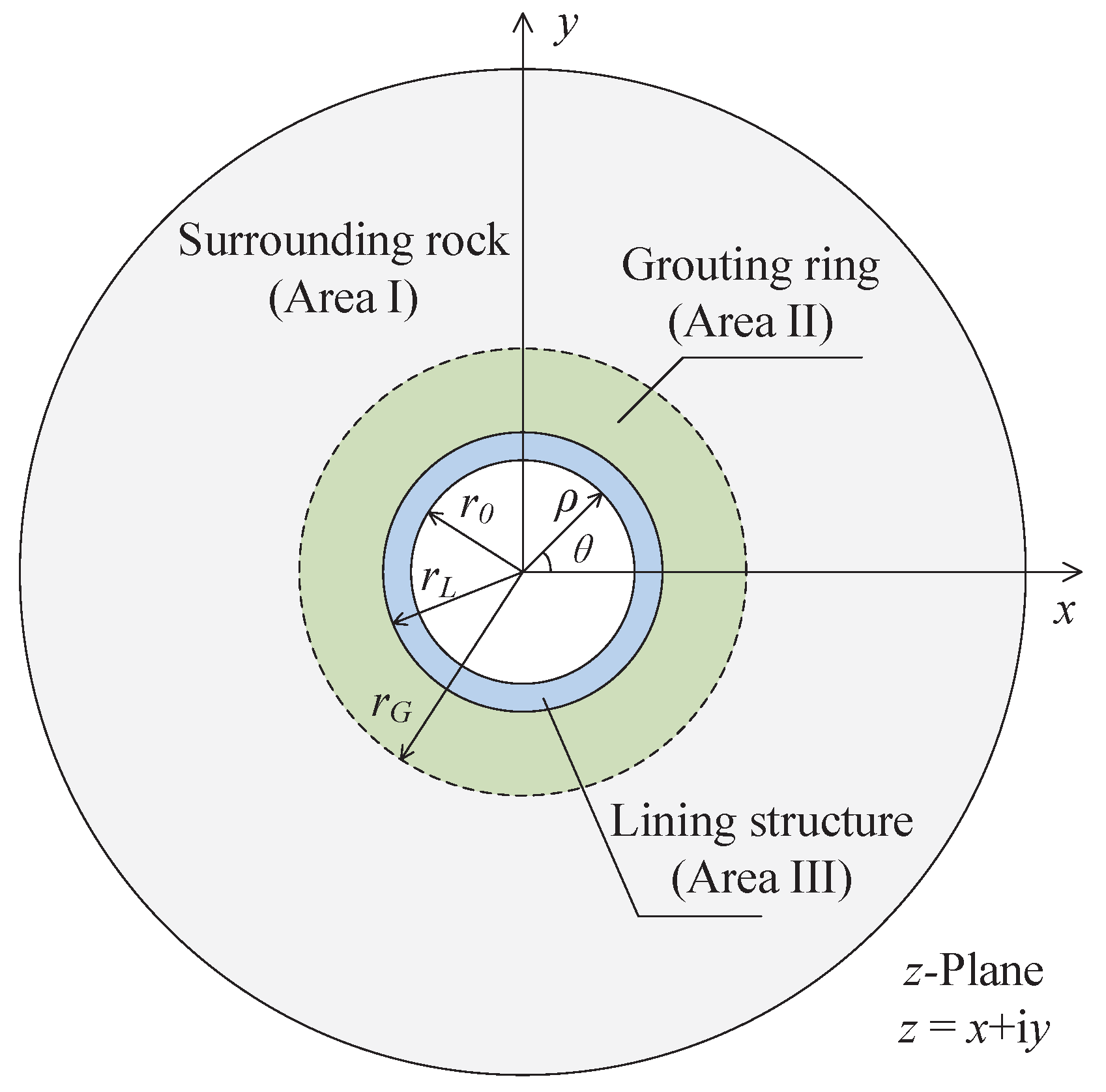
Based on the anisotropic seepage field calculation model proposed by Xu et al. [17], the tunnel seepage field calculation model is shown in Figure 1 considering the existance of a lining and grouting ring. The z -plane contains the area of surrounding rock (Area I), grouting ring (Area II) and lining structure (Area III). r 0 is the inner radius of the lining structure, r L is the outer radius of the lining structure, r G is the radius of the grouting ring and ρ is the distance from any point to the center of the tunnel. θ is the angle between any point and the x -axis. It is assuming that anisotropic seepage flow exists in surrounding rocks. The permeability coefficients of surrounding rock in horizontal direction (x direction) and vertical direction (y direction) are k x and k y , respectively. The lining structure and the grouting ring are continuous homogeneous and isotropic media with permeability coefficients of k L and k G , respectively.
In order to derive the analytical solution, the following assumptions are made:
(1) Anisotropic seepage flow exists in surrounding rocks; the permeability coefficients k x and k y in x and y directions has the following relationship n = k y / k x , where n defined as permeability coefficient ratio. The lining structure and the grouting ring are homogeneous, continuous and isotropic (Xu et al. [17]).
(2) Surrounding rocks and water are incompressible and have adequate groundwater recharge. The seepage is steady state and complies with Darcy’s law (Xu et al. [17]).
(3) The radius of a tunnel is much smaller than its buried depth. Therefore, a uniform distribution of total hydraulic head on the boundary between the grouting ring and surrounding rock (Atkinson and Mair [20]; Wang et al. [21]; Li et al. [22]).
(4) Only radial seepage is considered in the grouting ring and the lining structure (Pan et al. [23]).

2.2. Governing Equations and Boundary Conditions

The two-dimensional steady seepage field around the tunnel in the calculation model conforms to Laplace equation. Therefore, in the z -plane, the seepage differential equation in area I in the Cartesian coordinate can be obtained as [2]:
k x 2 φ S x 2 + k y 2 φ S y 2 = 0
where φ S is the total hydraulic head of surrounding rock.
The seepage differential equation in area II and III in the polar coordinate can be obtained as:
2 φ G ρ 2 + 1 ρ φ G ρ + 1 ρ 2 2 φ G θ 2 = 0
2 φ L ρ 2 + 1 ρ φ L ρ + 1 ρ 2 2 φ L θ 2 = 0
where φ G is the total hydraulic head of the grouting ring and φ L is the total hydraulic head of the lining structure. ρ is the polar diameter in polar coordinate and θ is the polar angle in polar coordinates as shown in Figure 1.
The deep buried tunnel and its corresponding lining structure and grouting ring are in area I, so the boundary conditions are as follows:
φ S ρ = ρ a ρ a = H a
φ S ρ = r G = φ G ρ = r G = H G
φ G ρ = r L = φ L ρ = r L = H L
φ L ρ = r 0 = H 0
where H a is the total hydraulic head at great distance, H 0 is the inner hydraulic head of the lining structure, H L is the hydraulic head between the lining structure and the grouting ring, and H G is the hydraulic head between the grouting ring and surrounding rock.

2.3. Analytical Solutions of Steady Seepage Field in Surrounding Rock

It is assumed that anisotropic seepage exists in the surrounding rock; the following coordinate transformation can be obtained:
x = n x y = y
So the governing Equation (1) can be transformed into:
2 φ S x 2 + 2 φ S y 2 = 0
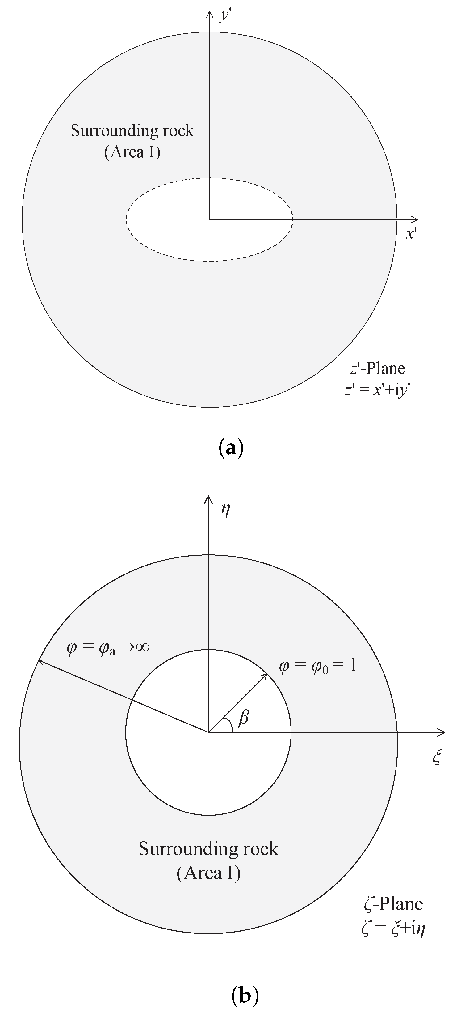
Therefore, the circular tunnel in the z-plane becomes an elliptical tunnel in the z –plane, which is shown in Figure 2a. The equation for the elliptical tunnel is as follows:
x 2 n r G 2 + y 2 r G 2 = 1
By conformal mapping, the area containing an elliptical tunnel in z –plane is projected to the area containing a circular tunnel with a radius of φ = 1 in ζ —plane (Zhou et al. [24]). The conformal mapping function is shown as follows:
z = ω ζ = R ζ + m ζ
in which:
z = x + i y
ζ = ξ + i η = φ e i β
R = n + 1 r G 2
m = n 1 n + 1
ξ , η and φ , β are the Cartesian and polar coordinates in the ζ -plane. Therefore, the coordinates of any point in the z-plane can be expressed by φ and β as follows:
x = R n φ + m φ cos β y = R φ m φ sin β
The seepage differential equation in ζ -plane also satisfies the Laplace equation. Equation (9) in the Cartesian coordinate of ζ -plane can be written as:
2 φ S ξ 2 + 2 φ S η 2 = 0
Equation (17) can be converted to polar coordinates as follows:
d d φ φ d φ S d φ = 0
The general solution of this Equation (18) is:
φ S = C 1 + C 2 ln φ
where C 1 and C 2 are undetermined constants, which are determined by boundary conditions. Boundary condition Equations (4) and (5) in ζ -plane can be written as:
φ S φ = φ a φ a = H a
φ S φ = φ 0 = 1 = H G
Substituting Equations (20) and (21) into Equation (19) can obtain:
C 1 = H G
C 2 = H a H G ln φ a
Therefore, Equation (19) can be rewritten as:
φ S = H G + H a H G ln φ a ln φ
The seepage discharge between area I and area II can be obtained by integrating Equation (24) as follows:
Q S = k x 0 2 π φ S φ φ d β = 2 π k x ln φ a H a H G
where Q S is the seepage discharge between area I and area II.

2.4. Analytical Solutions of Steady Seepage Field in Lining Structure and Grouting Ring

It is assumed that only radial seepage is considered in the grouting ring and the lining structure, the seepage in the grouting ring and the lining structure can be simplified as an axisymmetric steady seepage problem. Therefore, the governing Equations (2) and (3) can be simplified as:
2 φ G ρ 2 + 1 ρ φ G ρ = 0
2 φ L ρ 2 + 1 ρ φ L ρ = 0
According to boundary condition Equations (5)–(7), Equations (26) and (27) can be solved as:
φ G = H L ln r G H G ln r L ln r G / r L + H G H L ln r G / r L ln ρ
φ L = H 0 ln r L H L ln r 0 ln r L / r 0 + H L H 0 ln r L / r 0 ln ρ
The seepage discharge can be obtained by integrating Equations (28) and (29) respectively as follows:
Q G = k G 0 2 π φ G ρ ρ d θ = 2 π k G ln r G / r L H G H L
Q L = k L 0 2 π φ L ρ ρ d θ = 2 π k L ln r L / r 0 H L H 0
where Q G is the seepage discharge between area II and area III, and Q L is the seepage discharge inside area III.

2.5. Combined Analytical Solutions of Steady Seepage Field

According to continuous condition of seepage discharge, the seepage discharge between areas is equal as follows:
Q = Q S = Q G = Q L
According to Equations (25) and (30), it can be obtained:
H L = B + E F B H G + F E B H a
where B = k G k x , E = ln r G ln φ a , and F = ln r L ln φ a .
According to Equations (25) and (31), it can be obtained:
F G H a H G = D H L H 0
where D = k L k x , and G = ln r 0 ln φ a .
Substituting Equation (33) into (34) yields:
H G = B F + D E B G D F H a + B D H 0 B D + D E + B F D F B G
Substituting Equation (35) into (33) yields:
H L = B 2 F G + D F F E B B D + D E + B F D F B G H a + D B + E F B D + D E + B F D F B G H 0
By substituting (35) into (24), the seepage field of surrounding rock in ζ -plane can be obtained as follows:
φ S = ln φ ln φ a H a + 1 ln φ ln φ a B F + D E B G D F H a + B D H 0 B D + D E + B F D F B G
The seepage field of surrounding rock in z-plane can be obtained by transforming the seepage field in ζ –plane through Equation (16). However, Equation (16) is a transcendental equation, so the explicit solution can be obtained only on the x and y coordinate axes in the z-plane. For another arbitrary point ( x , y ) , it can be calculated by MATLAB.
For any point on the x coordinate axis, it can be obtained according to Equation (16):
φ = x n + x 2 n 2 n 2 1 r G 2 n + 1 r G
For any point on the y coordinate axis, it can be obtained according to Equation (16):
φ = y + y 2 n 2 1 r G 2 n + 1 r G
Subscribing Equations (38) and (39) into Equation (37), the analytical expression of total hydraulic head on the x and y coordinate axes in the z-plane can be obtained as follows, respectively:
φ S x = B F + D E B G D F H a + B D H 0 B D + D E + B F D F B G + 1 ln φ a B D H a H 0 B D + D E + B F D F B G ln x n + x 2 n 2 n 2 1 r G 2 n + 1 r G
φ S y = B F + D E B G D F H a + B D H 0 B D + D E + B F D F B G + 1 ln φ a B D H a H 0 B D + D E + B F D F B G ln y + y 2 n 2 1 r G 2 n + 1 r G
In addition, it can be obtained from Equation (24):
φ = φ a φ S H G H a H G
Substituting (42) into (16) shows that a circle with radius φ in the ζ -plane corresponds to an ellipse in the z-plane. Therefore, the hydraulic head contour line in the z-plane is an ellipse and its semi minor axis and semi major axis are as follows:
a φ = R n φ a φ S H G H a H G + m φ a H a H G φ S H G b φ = R φ a φ S H G H a H G m φ a H a H G φ S H G
where a φ and a β are the semi minor axis and semi major axis.

3. Verification of Analytical Solution of Seepage Field

Li et al. [25] proposed an analytical solution for the isotropic seepage field of a deep buried circular tunnel without lining structure and grouting ring as follows:
φ S = H 0 + H a H 0 ln r a r 0 ln r r 0
Corresponding to the solution in this paper, when there is no lining structure and grouting ring, there is:
r G = r L = r 0 H G = H L = H 0
Because the seepage filed is simplified as isotropic, there is n = 1. Equation (16) can be simplified as follows:
x = r 0 φ cos β y = r 0 φ sin β
Subscribing Equation (46) into Equation (24) yields:
φ S = H G + H a H G ln φ a ln x 2 + y 2 r 0
r a is assumed as the semi major axis length of the ellipse in z-plane, which the circle φ = φ a corresponded in the ζ –plane. According to Equation (16), the semi major axis of the ellipse in z-plane is as follows:
r a = n + 1 r 0 2 φ a m φ a
Subscribing n = 1 and m = 0 into Equation (48) yields:
r a = φ a r 0
Subscribing Equations (45) and (49) into the Equation (47), it can be found that the simplified proposed solution is identical with that proposed by Li et al. [25], which proves the correctness of the solution to some extent.
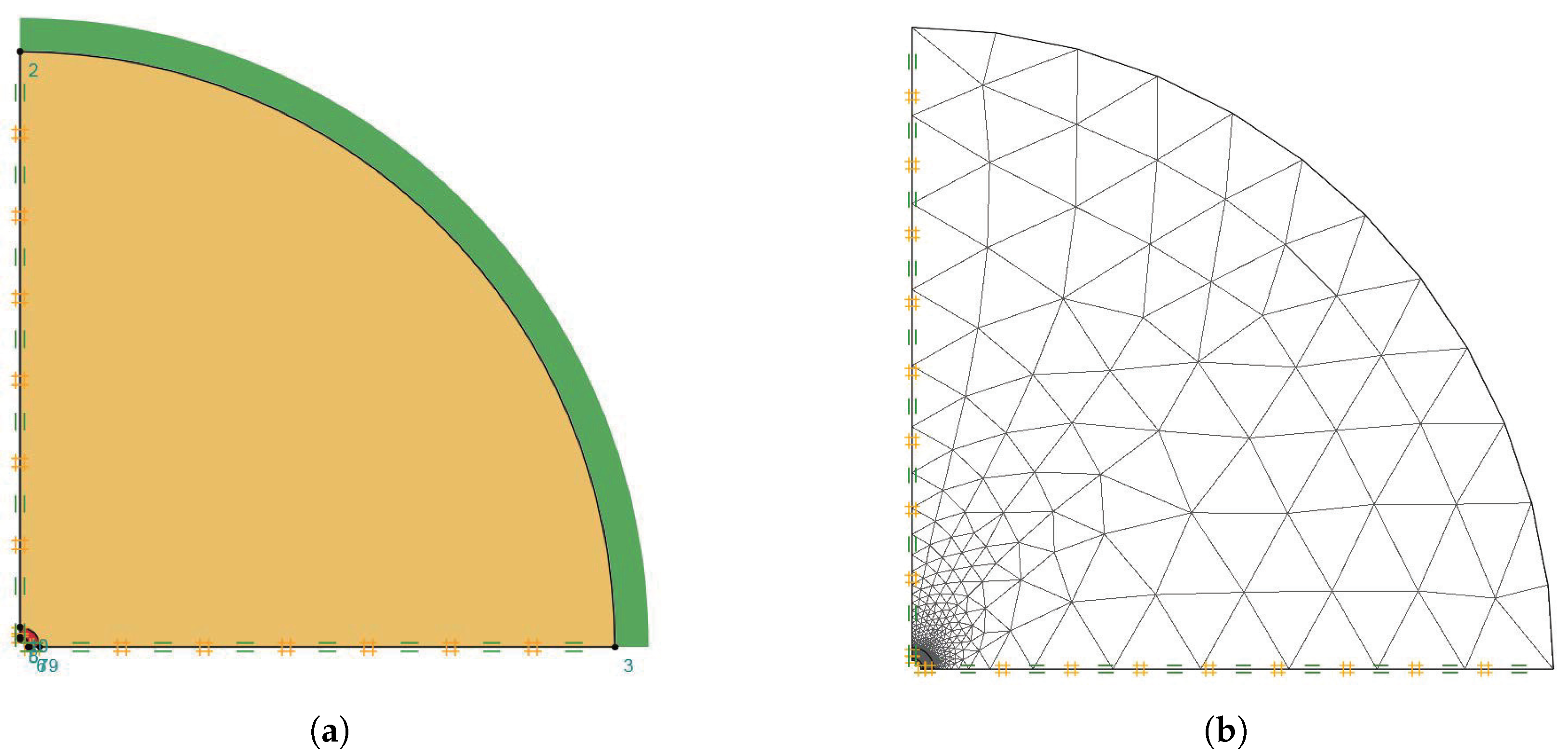
In order to further verify the correctness of the solution, an example comparison with numerical method is carried out. Finite element limit analysis software OptumG2 (Krabbenhoft et al. [26]) is used for numerical calculation of seepage field. Considering the symmetry of the calculation model, a quarter model is used to simulate the seepage field as shown in Figure 3a. The left and lower surrounding rock boundaries of the calculation model are set as impermeable boundaries with normal restraint. As it is a deep buried tunnel, uniform distributed total hydraulic heads are set along the outer boundary of the surrounding rock and the inner lining structure of the tunnel. The parameters used in numerical simulation are shown in Table 1. OptumG2 uses adaptive meshing method in the calculation, and the meshing is shown in Figure 3b.
From the derivation process of the solution in this paper, a specific value of φ a which meet the accuracy of general engineering is needed to obtain the seepage field. Li et al. [25] took φ a = 30 r 0 and Li et al. [27] took φ a = 20 r 0 in their research respectively. In the following calculation in this paper, φ a = 30 r 0 is adopted for calculation.
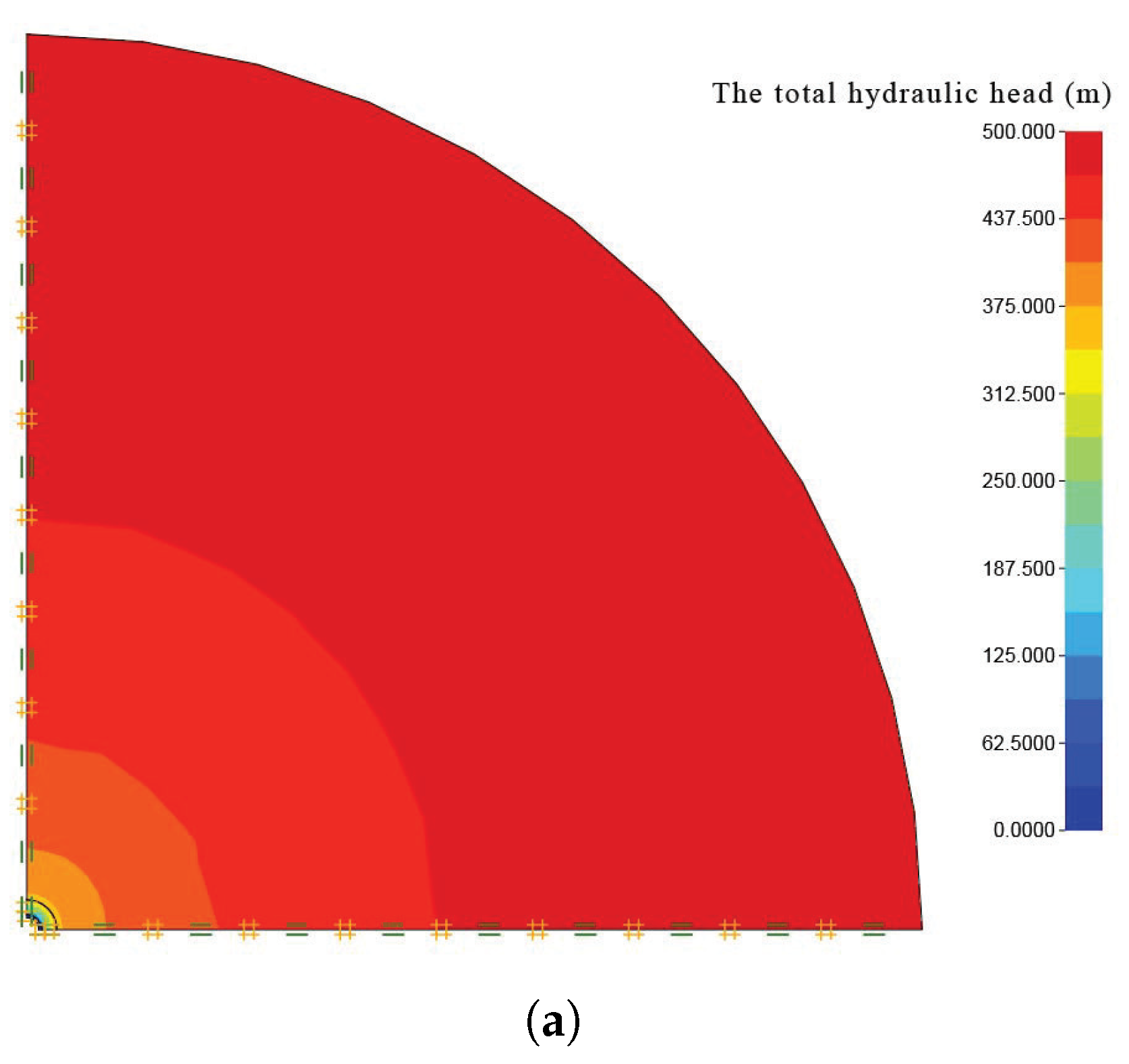
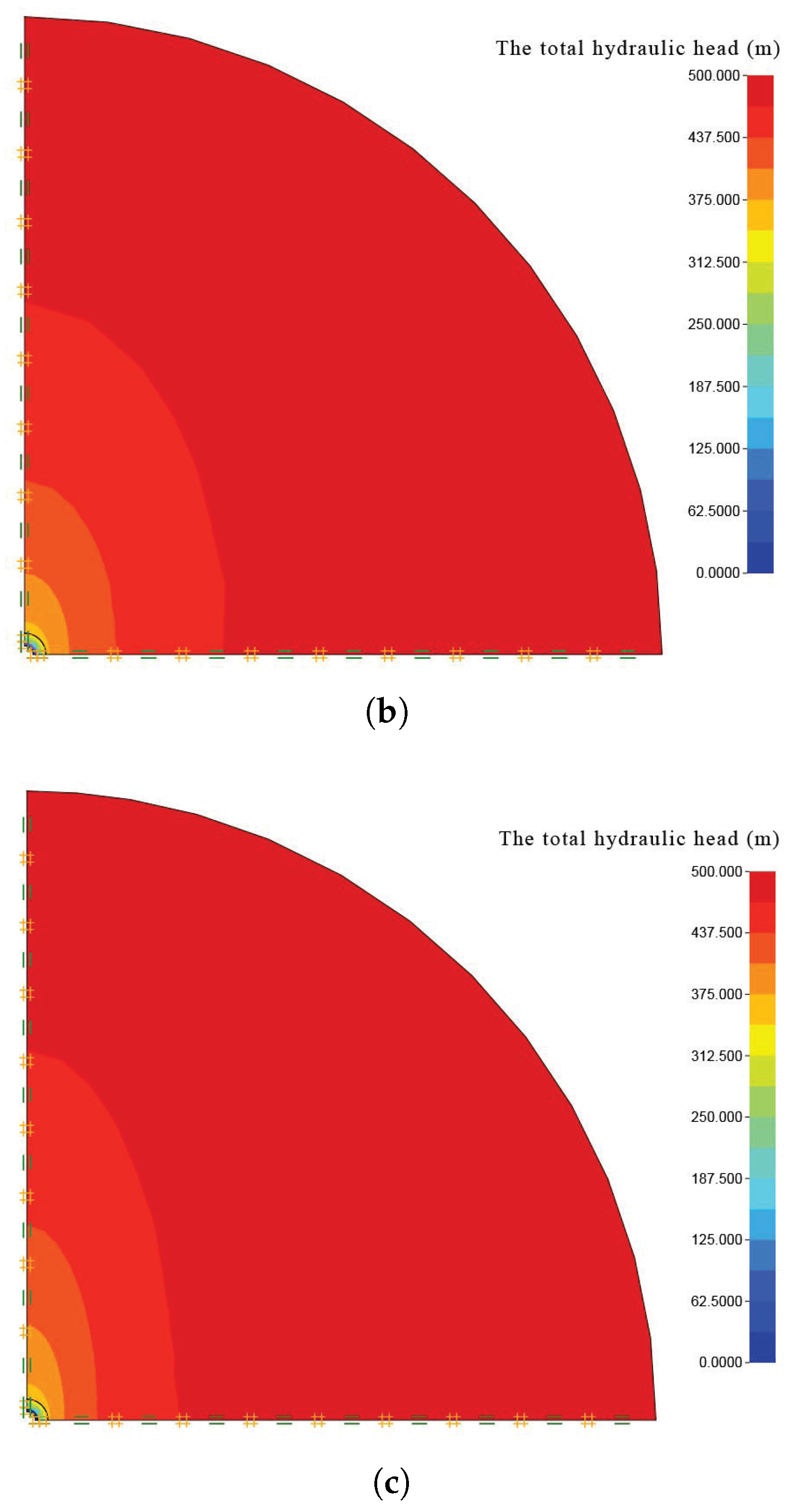
The results of the total hydraulic head by numerical simulation under different permeability coefficient ratio are shown in Figure 4. It can be seen from Figure 4a that the total hydraulic head contour of surrounding rock is circular when the permeability coefficients of surrounding rock in horizontal and vertical direction are the same, which means the seepage of surrounding rock is isotropic. When anisotropic seepage flow happens in surrounding rock around the deep buried tunnel, the total hydraulic head contour of surrounding rock is no longer uniformly circular distribution but elliptical distribution as shown in Figure 4b,c. The hydraulic gradient along y-axis which have a higher permeability coefficient is relatively smaller than that along the x-axis.
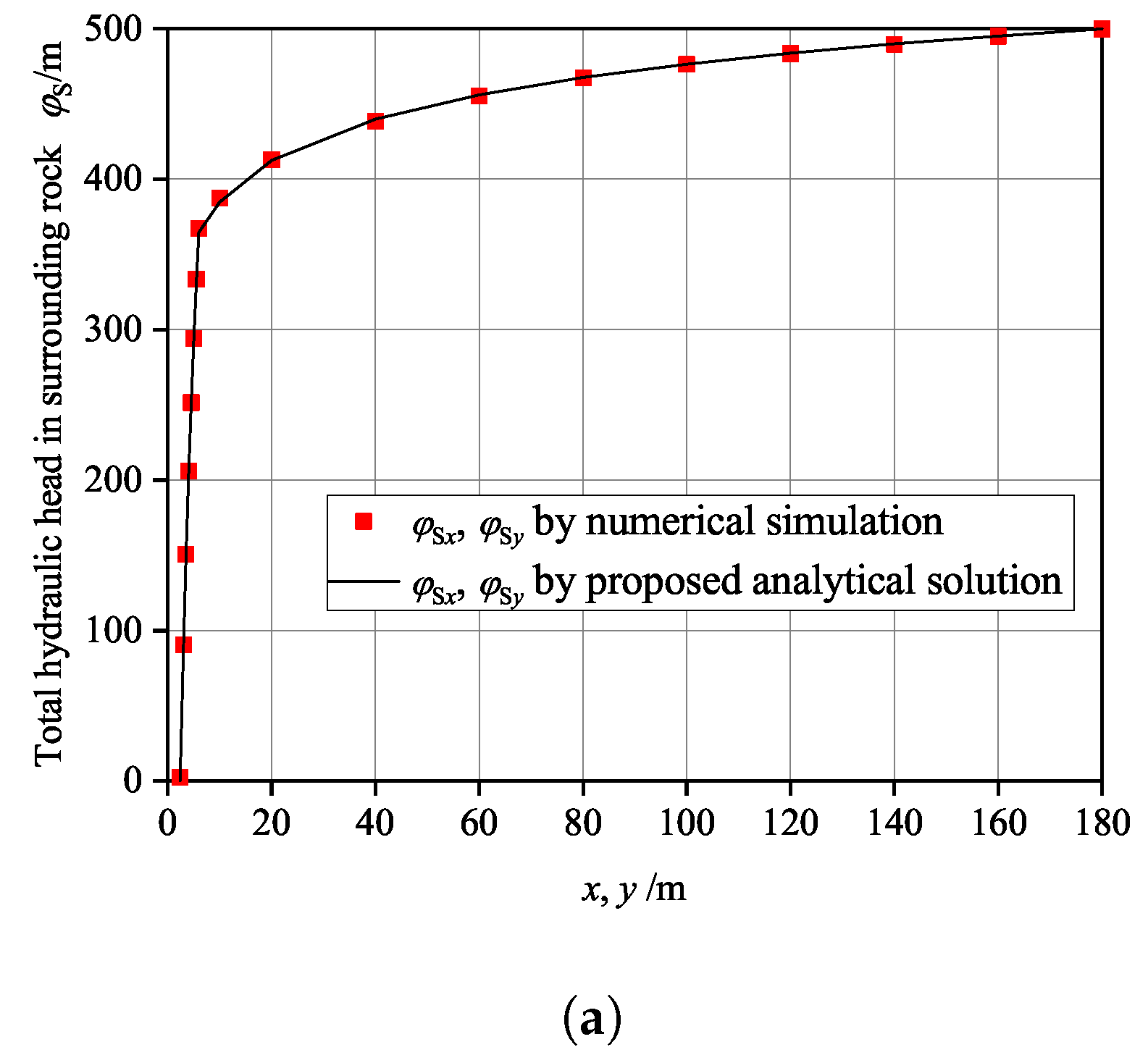
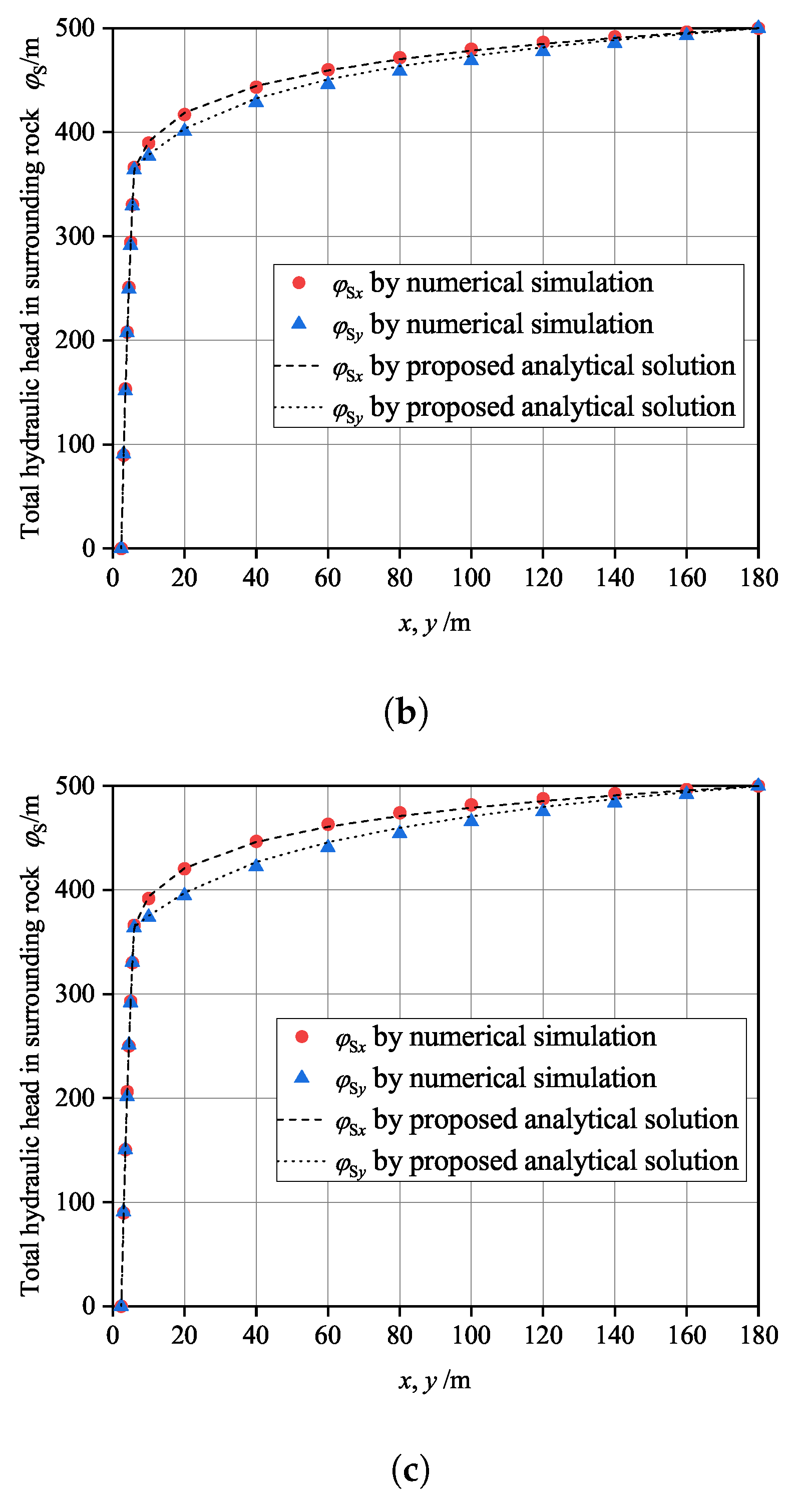
The results of total hydraulic head along coordinate axis calculated by numerical simulation and the proposed analytical solution are shown in Figure 5. It can be seen form Figure 5 that the results calculated by the proposed analytical solution are in agreement with those calculated by numerical simulation, which can verify the correctness of the proposed analytical solution in this paper.

4. Parameter Analysis of Analytical Solution of Seepage Field

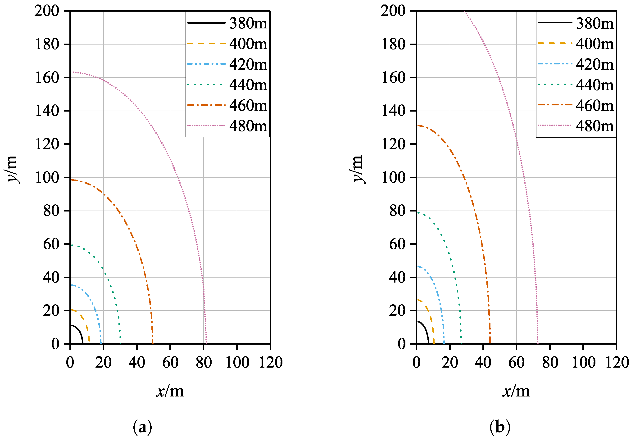
In order to further reveal the influence of anisotropy of permeability coefficient on seepage field of deep buried circular tunnel, the hydraulic head contour in surrounding rocks is calculated by proposed analytical solution. The parameters in Table 1 are used for the calculation, and a quarter of the calculation area is taken. The results are shown in Figure 6. Anisotropic seepage occurs when the permeability coefficient is anisotropic. The seepage field of surrounding rock around the buried circular tunnel is no longer uniformly distributed and presents elliptical distribution. Different head contour shapes occur with different permeability ratios of surrounding rocks. The hydraulic gradient is larger in the direction with smaller permeability coefficient, which is about n times of the direction with larger permeability coefficient.
The hydraulic head and seepage discharge between grouting ring and lining structure, and between grouting ring and surrounding rock are analyzed in following examples. The calculation parameters in examples are shown in Table 2.
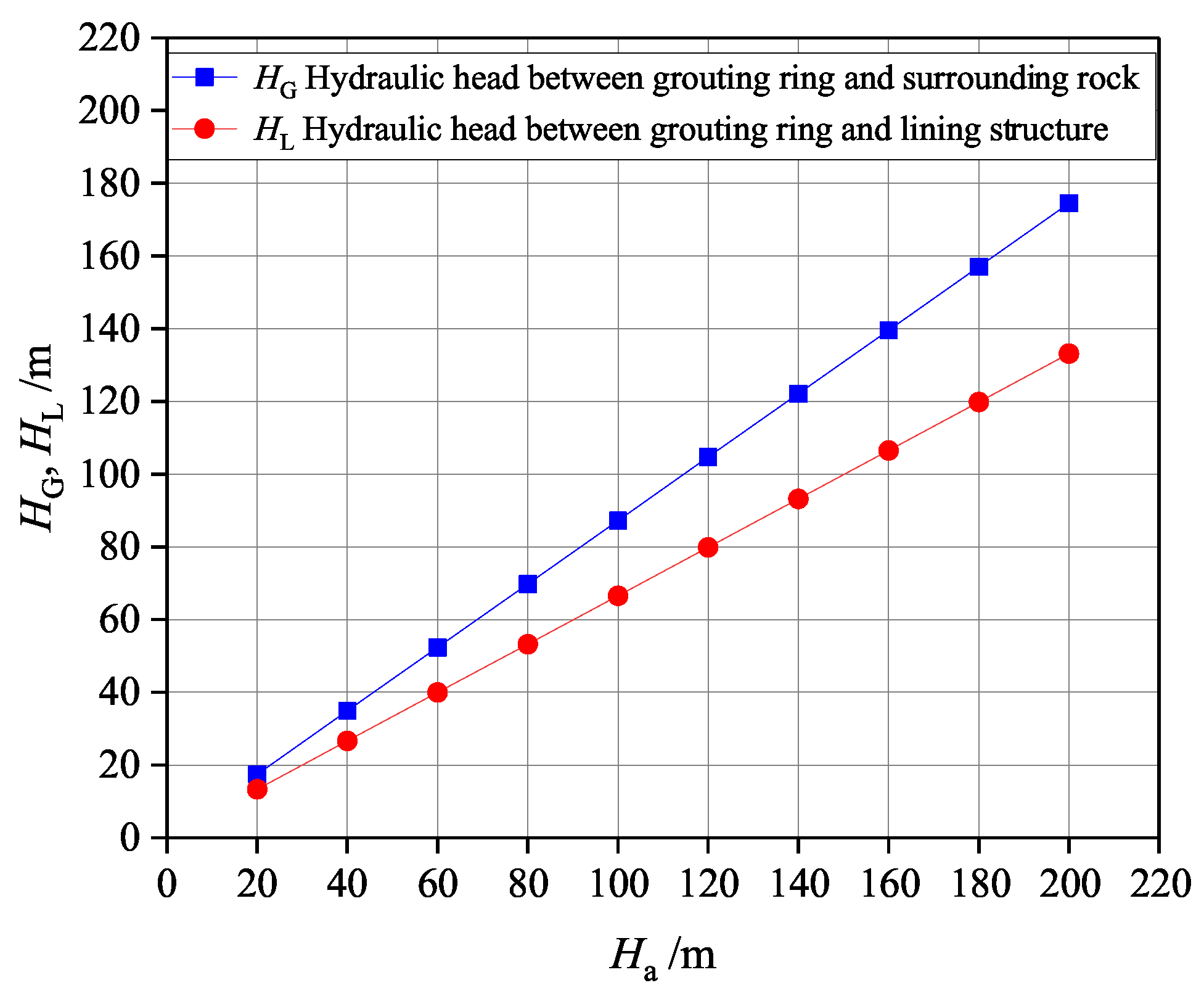
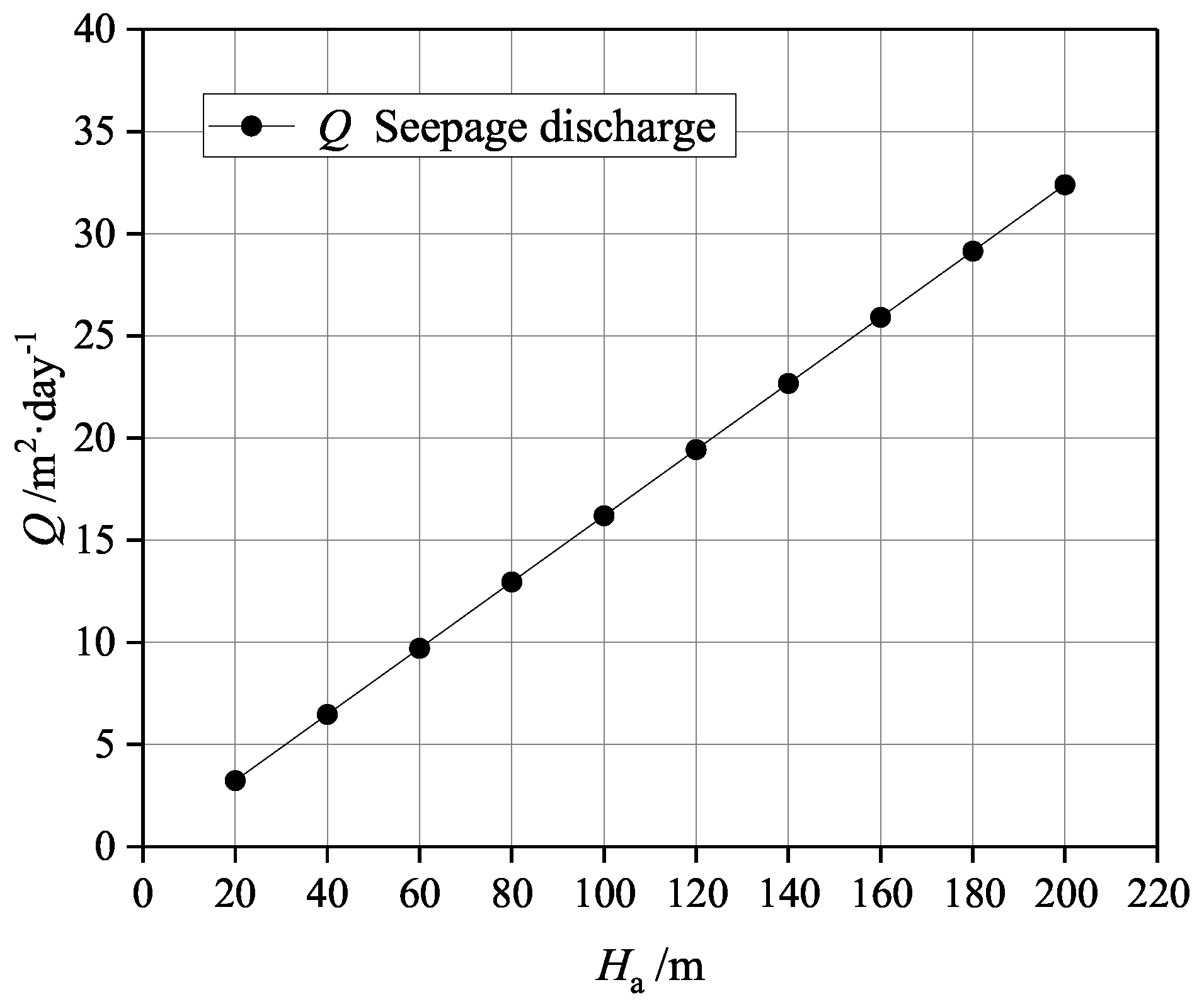
Figure 7 shows the hydraulic head between grouting ring and lining structure, and between grouting ring and surrounding rock under different total hydraulic head at infinite distance. The permeability coefficient of lining structure in this example is 1 × 10 8 m·s 1 . Figure 8 shows the seepage discharge under different total hydraulic head at infinite distance. It can be seen from the results that the hydraulic head of grouting ring and lining structure and the seepage discharge increase linearly with the increase of the total hydraulic head at infinite distance. Obviously, it can also be seen from Equations (30), (35) and (36) that the hydraulic head and seepage discharge have a linear relationship with the total hydraulic head at a very far distance when other parameters remain the same.
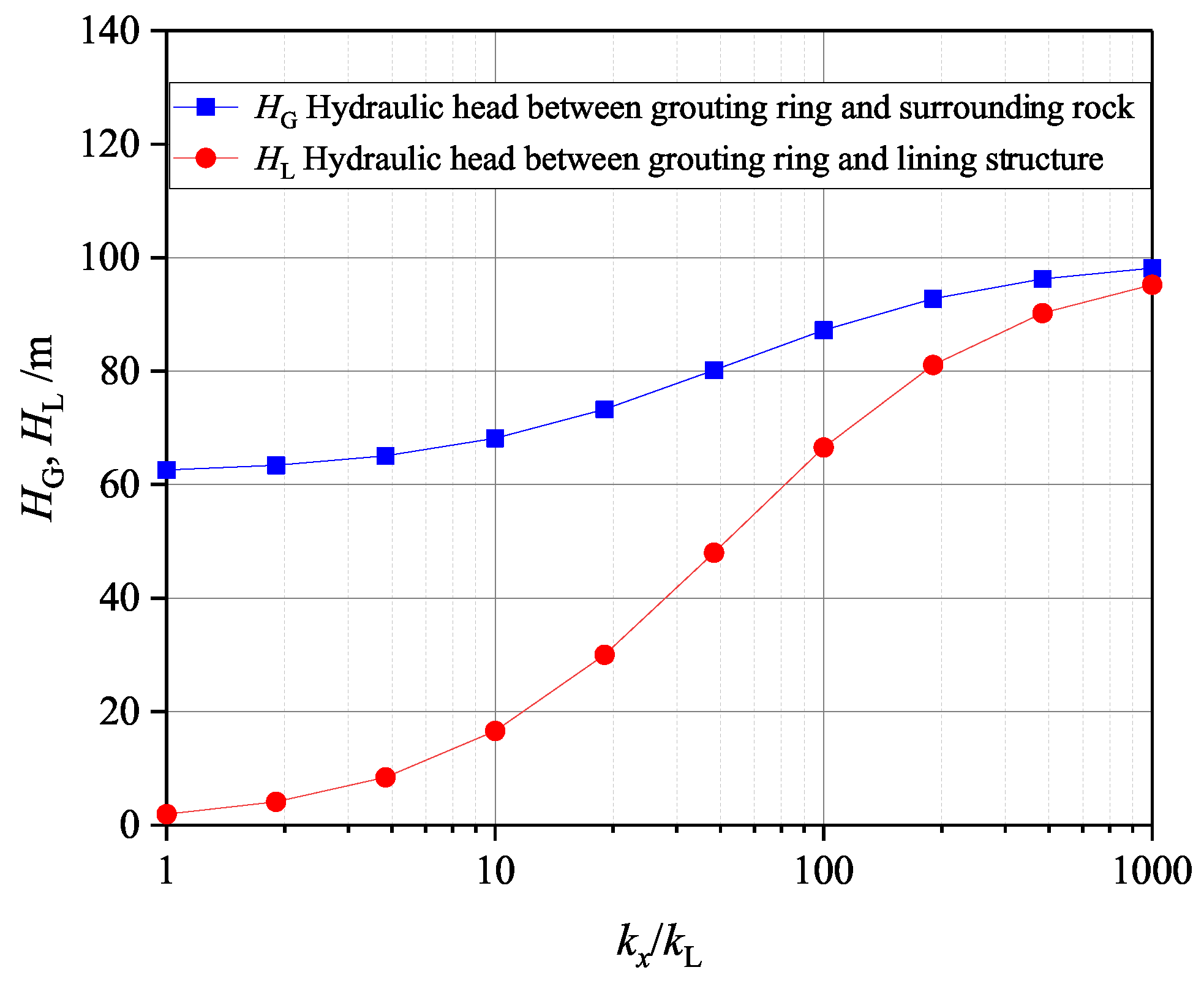
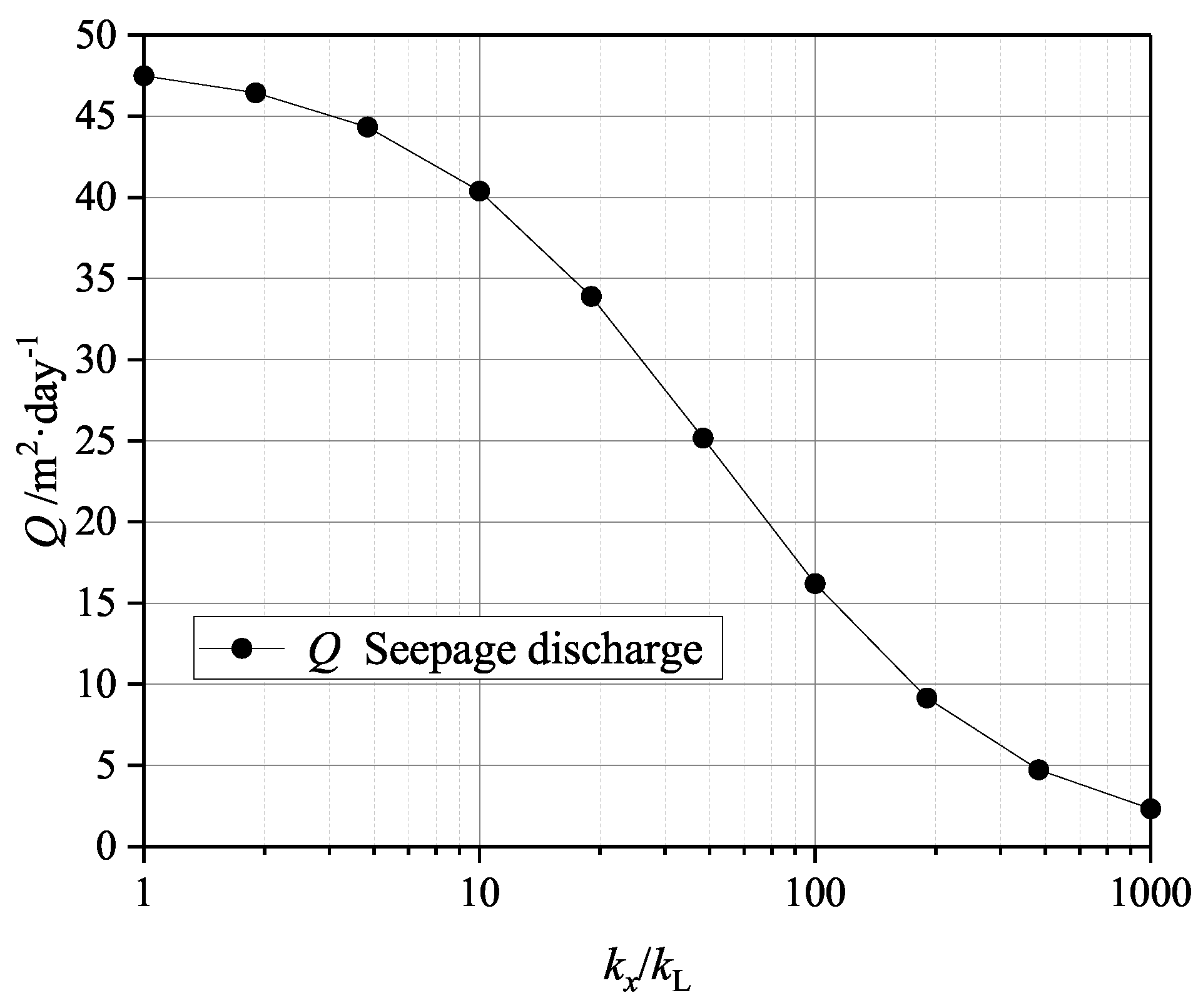
The following example will analyze the influence of the permeability coefficient of the lining structure on the hydraulic head and seepage discharge. The total hydraulic head at a large distance in this example is 100 m, and other calculation parameters are shown in Table 2. Figure 9 shows the hydraulic head of grouting ring and lining structure under a different permeability coefficient of lining structure. It can be found that with the decrease of the permeability coefficient of the lining structure, the hydraulic heads of the lining structure and the grouting ring are increased. When the difference between the permeability coefficient of the lining structure and surrounding rock is not large (e.g., k x / k L 100 ), the change of the permeability coefficient of the lining structure has a great impact on the hydraulic head. However, when the permeability coefficient of lining structure differs greatly from that of surrounding rock (e.g., k x / k L > 100 ), the influence of the permeability coefficient of lining structure on hydraulic head is no longer significant. Because when the permeability coefficient differs greatly, the lining structure can be considered as impermeable, so the hydraulic head of lining structure will be close to the total hydraulic head at infinity. Figure 10 shows the seepage discharge under different permeability coefficient of lining structure. It can also be seen that when the difference of permeability coefficient is small (e.g., k x / k L 100 ), the decrease of lining structure permeability coefficient greatly reduces the seepage discharge. However, when the difference of permeability coefficient is large (e.g., k x / k L > 100 ), the decrease of lining permeability coefficient has little impact on the seepage discharge, and the seepage discharge tends to be zero.
Wang [28] and Liu et al. [29] pointed out that the water shall be blocked by grouting ring for deep buried tunnels with hydraulic head greater than 60 m. Wang et al. [21] studied water pressure distribution on tunnel lining and the results indicated that the grouting ring effectively reduced the water pressure on tunnel lining. Seikan tunnel in Japan and Yuanliangshan tunnel in China both adopt this method (Zhang [30]).
Grouting ring is widely used as water plugging method in subsea tunnel. It is important to determine the influence of grouting ring parameters on hydraulic head and seepage discharge for the design of subsea tunnel. According to Equation (7), the internal hydraulic head of lining structure is 0, Equations (31) and (36) can be written as follows:
H L = k x k L ln r L r 0 ln φ a + k x k L ln r L r 0 + k x k G ln r G r L H a
Q = 2 π k x ln φ a + k x k L ln r L r 0 + k x k G ln r G r L H a
Pan et al. [23] proposed an influence factor for grouting parameters. With reference to this influence factor, the grouting influence factor is defined as follows:
F G = k x k G ln r G r L
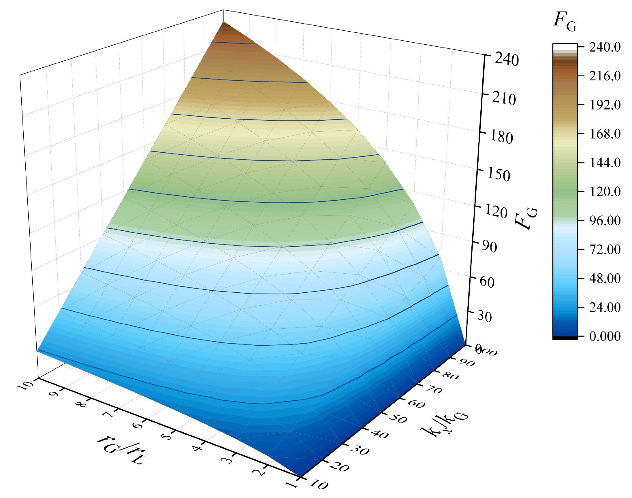
where is k x / k G the ratio of permeability coefficient between surrounding rock and grouting ring, which reflects the impermeability of the grouting ring. r G / r L is the ratio of the grouting circle radius to the tunnel outer diameter, reflecting the size of the grouting ring.
According to Equations (50) and (51), when other parameters are determined, the hydraulic head of the lining structure and seepage discharge will be determined by the grouting influence factor. The larger the grouting influence factor is, the smaller the hydraulic head of lining structure is, and the smaller the seepage discharge is.
The variation of grouting influence factor with k x / k G and r G / r L is shown in Figure 11. It can be seen from the results in the diagram that the grouting influence factor shows a linear growth trend with the increase of k x / k G and a logarithmic growth trend with the increase of r G / r L . The size of the grouting ring has a more significant effect on the grouting influence factor. In practical engineering, the adjustment range of grouting ring permeability is larger than that of grouting ring size for economic reasons. Therefore, in engineering design, the minimum value of permeability of grouting ring, i.e., the maximum value of k x / k G can be determined first, and then the grouting ring size can be determined on this basis.

5. Conclusions

Based on the existing theoretical research of the tunnel seepage flow field for a deep-buried tunnel, analytical solutions of the steady seepage field for a deep-buried tunnel with grouting ring are proposed considering different permeability coefficients of surrounding rocks in horizontal and vertical directions i.e., the anisotropic seepage flow and considering the influence of tunnel lining structure and grouting ring. Through coordinate transformation and conformal mapping, the seepage field of surrounding rock is solved. Then the seepage fields of surrounding rock, grouting ring and lining structure are solved by boundary conditions and continuous flow conditions between them. Verification analysis and parameter analysis are carried out, several conclusions can be drawn as follows:
(1) The analytical solution of the anisotropic seepage field of surrounding rock proposed in this paper is completely consistent with the analytical solution of isotropic seepage field in the case of simplification, which proves the correctness of the solution in this paper to some extent.
(2) For the anisotropic seepage field of a deep buried tunnel with grouting ring, the calculation results of the analytical solution in this paper are completely consistent with the calculation results of the finite element limit analysis software OptumG2, which can verify the correctness of the solution in this paper.
(3) The seepage field of surrounding rocks around a deep buried circular tunnel is no longer uniformly distributed and presents elliptical distribution, after considering anisotropic seepage flow. Under different permeability coefficient ratios of surrounding rocks, different results of the hydraulic head contour are presented. In the direction of a smaller permeability coefficient, the hydraulic gradient is larger.
(4) As the permeability coefficient of a lining structure decreases, the hydraulic head of the lining structure and grouting ring are increased. When the difference between permeability coefficient of lining structure and surrounding rock is not very large, the change of permeability coefficient of lining structure has a great influence on the hydraulic head. However, when the permeability coefficient of the lining structure differs greatly from that of the surrounding rock, the change of the permeability coefficient of lining structure has no significant effect on the hydraulic head.
(5) The parameters of grouting ring are analyzed by using the grouting influence factors. The results show that the size of grouting ring has more significant influence on the grouting effect.
Author Contributions

Conceptualization, Q.C.; Project administration, Q.C.; Software, B.Z. and L.L.; Validation, C.X. and J.M.; Writing—original draft, L.L. and Q.C.; Writing—review & editing, Q.C. and B.K. All authors have read and agreed to the published version of the manuscript.

Funding

The financial supports from National Natural Science Foundation of China (NSFC Grant No. 52008373) and Natural Science Foundation of Zhejiang Province of China (No. LQ22E080009) are greatly acknowledged.

Institutional Review Board Statement

Not applicable.

Informed Consent Statement

Not applicable.

Data Availability Statement

Not applicable.

Conflicts of Interest

The authors declare no conflict of interest.

References

  1. Ahmad, S.; Naji, A.M.; Hussain, I.; Rehman, H.; Yoo, H. Ground saturation response during first filling of lined pressure tunnels: A case study. Rock Mech. Rock Eng. 2021, 54, 513–535. [Google Scholar] [CrossRef]
  2. Harr, M.E. Groundwater and Seepage; McGraw-Hill: New York, NY, USA, 1962. [Google Scholar]
  3. Fernández, G.; Alvarez, T.A., Jr. Seepage-induced effective stresses and water pressures around pressure tunnels. J. Geotech. Eng. 1994, 120, 108–128. [Google Scholar] [CrossRef]
  4. Qin, Z.; Wang, Y.; Song, Y.; Dong, Q. The analysis on seepage field of grouted and shotcrete lined underwater tunnel. Math. Probl. Eng. 2020, 2020, 7319054. [Google Scholar] [CrossRef]
  5. Li, Z.; He, C.; Chen, Z.; Yang, S.; Ding, J.; Pen, Y. Study of seepage field distribution and its influence on urban tunnels in water-rich regions. Bull. Eng. Geol. Environ. 2019, 78, 4035–4045. [Google Scholar] [CrossRef]
  6. Park, K.H.; Owatsiriwong, A.; Lee, J.G. Analytical solution for steady-state groundwater inflow into a drained circular tunnel in a semi-infinite aquifer: A revisit. Tunn. Undergr. Space Technol. 2008, 23, 206–209. [Google Scholar] [CrossRef]
  7. Kolymbas, D.; Wagner, P. Groundwater ingress to tunnels–the exact analytical solution. Tunn. Undergr. Space Technol. 2007, 22, 23–27. [Google Scholar] [CrossRef]
  8. Lei, S. An analytical solution for steady flow into a Ttonnel. Groundwater 1999, 37, 23–26. [Google Scholar] [CrossRef]
  9. El Tani, M. Circular tunnel in a semi-infinite aquifer. Tunn. Undergr. Space Technol. 2003, 18, 49–55. [Google Scholar] [CrossRef]
  10. Wu, J.; Zhou, Z.; Zhuang, C. A combined analytical-numerical method for groundwater inflow into circular tunnels in drained conditions. Hydrogeol. J. 2021, 29, 2529–2543. [Google Scholar] [CrossRef]
  11. Guo, Y.; Wang, H.; Jiang, M. Efficient Iterative Analytical Model for Underground Seepage around Multiple Tunnels in Semi-Infinite Saturated Media. J. Eng. Mech. 2021, 147, 04021101. [Google Scholar] [CrossRef]
  12. Luo, X.; Xiang, Y.; Yu, C. A Semi-Analytical Model and Parameter Analysis of a Collaborative Drainage Scheme for a Deeply Buried Tunnel and Parallel Adit in Water-Rich Ground. Appl. Sci. 2022, 12, 3759. [Google Scholar] [CrossRef]
  13. Ying, H.W.; Zhu, C.W.; Gong, X.N.; Wang, X. Analytical solutions for the steady-state seepage field in a finite seabed with a lined tunnel. Mar. Georesour. Geotechnol. 2019, 37, 972–978. [Google Scholar] [CrossRef]
  14. Mitchell, J.K.; Soga, K. Fundamentals of Soil Behavior; John Wiley & Sons: New York, NY, USA, 2005; Volume 3. [Google Scholar]
  15. Zienkiewicz, O.; Mayer, P.; Cheung, Y.K. Solution of anisotropic seepage by finite elements. J. Eng. Mech. Div. 1966, 92, 111–120. [Google Scholar] [CrossRef]
  16. Hu, Z.; Yang, Z.X.; Wilkinson, S.P. Active earth pressure acting on retaining wall considering anisotropic seepage effect. J. Mt. Sci. 2017, 14, 1202–1211. [Google Scholar] [CrossRef]
  17. Xu, C.; Liang, L.; Ding, W. Analytical Solutions on Steady Seepage Field of Deep Buried Circular Tunnel After Considering Anisotropic Flow. J. Shanghai Jiaotong Univ. 2018, 52, 1565. [Google Scholar]
  18. Tang, Y.; Chan, D.H.; Zhu, D.Z. Analytical solution for steady-state groundwater inflow into a circular tunnel in anisotropic soils. J. Eng. Mech. 2018, 144, 06018003. [Google Scholar] [CrossRef]
  19. Luo, S.; Xu, M.; Kang, X.; Li, X.; Rao, L. Analytical solution of external water pressure on deep tunnel lining in horizontally layered hydrogeological structures. Bull. Eng. Geol. Environ. 2022, 81, 1–13. [Google Scholar] [CrossRef]
  20. Atkinson, J.; Mair, R. Loads on leaking and watertight tunnel linings, sewers and buried pipes due to groundwater. Geotechnique 1983, 33, 341–344. [Google Scholar] [CrossRef]
  21. Wang, X.; Tan, z.; Wang, M.; Zhang, M.; Ming, H. Theoretical and experimental study of external water pressure on tunnel lining in controlled drainage under high water level. Tunn. Undergr. Space Technol. 2008, 23, 552–560. [Google Scholar] [CrossRef]
  22. Li, P.; Zhang, D.; Zhao, Y.; Zhang, C. Study of distribution law of water pressure acting on composite lining and reasonable parameters of grouting circle for subsea tunnel. Chin. J. Rock Mech. Eng. 2012, 31, 280–288. [Google Scholar]
  23. Pan, Y.; Luo, Q.; Zhou, B.; Chen, J. Analytical study on seepage field of deep tunnel with grouting circle in half plane. J. ZheJiang Univ. Eng. Sci. 2018, 52, 1114–1122. [Google Scholar]
  24. Zhou, H.; Liu, H.; Kong, G.; Cao, Z. Analytical solution for pressure-controlled elliptical cavity expansion in elastic–perfectly plastic soil. Geotech. Lett. 2014, 4, 72–78. [Google Scholar] [CrossRef]
  25. Li, Z.; Ren, Q.; Wang, Y. Elasto-plastic analytical solution of deep-buried circle tunnel considering fluid flow field. Chin. J. Rock Mech. Eng. 2004, 23, 1291–1295. [Google Scholar]
  26. Krabbenhoft, K.; Lyamin, A.; Krabbenhoft, J. Optum computational engineering (OptumG2). Comput. Softw. 2015. [Google Scholar]
  27. Li, P.; Fang, Q.; Zhang, D. Analytical solutions of stresses and displacements for deep circular tunnels with liners in saturated ground. J. Zhejiang Univ. Sci. A 2014, 15, 395–404. [Google Scholar] [CrossRef] [Green Version]
  28. Wang, M.; Huang, F. Key problems on subsea tunnel construction. J. Archit. Civ. Eng. 2005, 22, 1–4. [Google Scholar]
  29. Liu, Z.W.; Zhang, D.L.; Zhang, M.Q. Grouting technique for high-pressure and water-rich area in Maoba syncline at Yuanliangshan tunnel. Chin. J. Rock Mech. Eng. 2005, 24, 1728–1734. [Google Scholar]
  30. Zhang, C.; Zhang, D.L.; Wang, M.S.; Xiang, Y.Y. Study on appropriate parameters of grouting circle for tunnels with limiting discharge lining in high water pressure and water-enriched region. Chin. J. Rock Mech. Eng. 2007, 26, 2270–2276. [Google Scholar]
Figure 1. Calculation model of steady seepage field for deep-buried tunnel.
Jmse 10 01861 g001
Figure 2. Calculation model after coordinate transformation and conformal mapping. (a) Plane of coordinate transformation. (b) Plane of conformal mapping.
Jmse 10 01861 g002
Figure 3. Finite element limit analysis model and meshing. (a) Calculation model. (b) Adaptive meshing.
Jmse 10 01861 g003
Figure 4. Total hydraulic head of lining structure, grouting ring and surrounding rock by numerical simulation. (a) n = 1 . (b) n = 2 . (c) n = 3 .
Jmse 10 01861 g004aJmse 10 01861 g004b
Figure 5. Total hydraulic head along coordinate axis. (a) n = 1 . (b) n = 2 . (c) n = 3 .
Jmse 10 01861 g005aJmse 10 01861 g005b
Figure 6. Total hydraulic head along coordinate axis. (a) n = 2 . (b) n = 3 .
Jmse 10 01861 g006
Figure 7. Hydraulic head of grouting ring and lining structure under different total hydraulic head at infinite distance.
Jmse 10 01861 g007
Figure 8. Seepage discharge under different total hydraulic head at infinite distance.
Jmse 10 01861 g008
Figure 9. Hydraulic head of grouting ring and lining structure under different permeability coefficient of lining structure.
Jmse 10 01861 g009
Figure 10. Seepage discharge under different permeability coefficient of lining structure.
Jmse 10 01861 g010
Figure 11. Grouting influence factors under different grouting ring parameters.
Jmse 10 01861 g011
Table 1. Calculation parameters in numerical simulation.
r 0 /m r L /m r G /m k L /m·s 1 k G /m·s 1 k x /m·s 1 n H 0 /m H a /m
2.436 1 × 10 6 1 × 10 6 1 × 10 5 1 to 30500
Table 2. Calculation parameters in parameter analysis.
r 0 /m r L /m r G /m k L /m·s 1 k G /m·sy 1 k x /m·s 1 n H 0 /m H a /m
2.436 1 × 10 5 to 1 × 10 8 1 × 10 6 1 × 10 5 2020 to 220
Publisher’s Note: MDPI stays neutral with regard to jurisdictional claims in published maps and institutional affiliations.