Article

Research on the Enhancement of the Separation Efficiency for Discrete Phases Based on Mini Hydrocyclone

1
School of Mechanical Science and Engineering, Northeast Petroleum University, Daqing 163318, China
2
Heilongjiang Key Laboratory of Petroleum and Petrochemical Multiphase Treatment and Pollution Prevention, Daqing 163318, China
3
Institute of Process Engineering, Chinese Academy of Sciences, Beijing 100190, China
4
Wuhan Chutian Jialian Technology Co., Ltd., Wuhan 430223, China
*
Author to whom correspondence should be addressed.
J. Mar. Sci. Eng. 2022, 10(11), 1606; https://doi.org/10.3390/jmse10111606
Submission received: 24 September 2022 / Revised: 17 October 2022 / Accepted: 21 October 2022 / Published: 31 October 2022

Abstract

:
The economic and efficient treatment of mixed media in offshore produced fluids is of great significance to oilfield production. Due to the small space and limited load-bearing capacity of offshore platforms, some mature multiphase media separation processes in onshore oilfields are difficult to apply. Therefore, high-efficiency processing methods with small-occupied space are required. Mini hydrocyclones (MHCs) are a potential separation method due to their simple structure, small footprint, and high separation efficiency (especially for fine particles or droplets). However, for discrete phases with different densities and sizes, the enhancement rule of the separation efficiency of MHCs is not yet clear. In this paper, numerical simulation methods were used to study the separation performance of hydrocyclones with different main diameters (including conventional hydrocyclones (CHCs) and MHCs) for discrete phases with different densities and particle sizes. Results show that MHC has the optimal enhancement range for oil–water separation when oil-droplet sizes are 60–300 μm, while the optimal enhancement range for silica particle and water separation is 10–40 μm. For other droplet/particle size ranges, the efficiency enhancement effect of MHC is not obvious compared to conventional hydrocyclones. By calculating the radial force of particles in MHC and CHC, the reasons for the enhanced efficiency of MHC are theoretically analyzed. The pressure drop of MHC is higher than CHC under the same feed velocity, which can be improved by connecting CHC with MHC. Additionally, the fluid velocity test experiments based on particle image velocimetry (PIV) were carried out to verify the accuracy of the numerical simulations. This study clarified the scope of application of MHCs to different discrete phase types, in order to provide a basis for the precise application of MHCs.

Graphical Abstract

1. Introduction

With the rise in the consumption of oil resources, the major oil companies in the world pay more and more attention to the exploration and development of offshore oil, and the proportion of offshore oil resources is gradually increasing [1]. Offshore oil production accounts for about 30% of the total production in 2009 [2]. Produced water (PW), the largest by-product of most offshore oil and gas production operations, is the wastewater generated when water from underground is brought to the surface during the extraction process [3,4]. The water concentration of produced fluids from offshore fields worldwide is approximately 75–80% [5,6], and this proportion can reach 98% in the late stage of oilfield production, resulting in serious challenges to the economic benefits of production. With the development of the global offshore oil and gas industry, the illegal discharge of PW has attracted more and more attention due to the pollution of waters near offshore platforms. In addition to organic pollutants, PW also contains heterogeneous media such as oil and suspended solids. Efficient separation of heterogeneous media in PW is one of the important tasks in reducing the disturbance to the marine ecological environment during offshore oil and gas production [3]. From an economic point of view, water management costs range from 5–15% of drilling costs [4]. Therefore, it is of great significance to select the appropriate PW treatment process and technology in offshore oil and gas production.
Conventional treatment techniques for PW on offshore platforms include gravity sedimentation, air flotation, filtration, membrane separation, hydrocyclone, etc. [7]. Gravity sedimentation technology is the most adaptable, lowest cost and simplest technology among the various treatment technologies. However, gravity sedimentation tanks take up considerable space and the separation speed is slow. Conventional sedimentation tanks have problems such as low separation efficiency for fine oil droplets/particles. Air flotation technology has the advantages of high separation efficiency and low cost, while this method uses a large number of chemicals during operation and has limitations such as slow separation speed and large equipment space. Regarding filtration technology, it can obtain higher separation efficiency and has a relatively small footprint for the devices. The complex operation and the discontinuity of the separation process caused by periodic backwashing are the current problems of filtration technology. The membrane separation technique has shown great potential in removing oil from wastewaters effectively [8]. It usually has a higher purification efficiency than filtration, although both purification principles are similar. The obvious shortcoming of membrane separation is the lower capacity (water-flux). Mousa et al. improved the capacity by developing the PSF/CA/ZnO membrane [9,10] and PSF-based nanofiber membrane [11]. Nonetheless, the membrane separation process still has challenges in operation and maintenance simplicity and service life.
Hydrocyclones, as a type of centrifugal separation device, have been widely implemented in the separation of heterogeneous media in the petrochemical field [12,13,14,15,16], due to several advantages such as simple geometrical structure, small footprint, low operating costs, easy maintenance, and high separation efficiency [17,18,19,20,21]. Generally, hydrocyclones contain one or several tangential inlets, a cylindrical section (also named swirl cavity [22]), one or two conical sections, an overflow outlet and underflow outlet, as presented in Figure 1. Among these, Dc represents the main diameter of the hydrocyclone, which is usually the basis of the design of other dimension parameters [23]; Do and Du mean the overflow and underflow outlet diameters; a and b represent the height and width of the tangential inlet; Lc and Lv are the cylindrical segment height and the vortex finder length, respectively; θ means the angle of cone section. The mixed liquid enters the hydrocyclone through tangential inlets at a certain feed velocity and, under the action of centrifugal force, most of the light phase with less density spirally moves to the central area of hydrocyclone and then moves toward the overflow outlet. Contrarily, most of the heavy phase with higher density moves spirally along the inner wall of th ehydrocyclone and is discharged from the underflow outlet, thus finally realizing the separation of two or more phases. The above process achieves the separation of the two phases.
However, the conventional hydrocyclone (CHC) experiences an unsatisfactory effect in fine particle/droplet separations. Characterized by solid particles heavier than the continuous water phase, CHCs are suitable for the separation of particles with a large particle size distribution, while they are difficult to separate fine particles/droplets efficiently [24], especially for particles smaller than 10 μm [25], which limits the applications of CHCs. In response to the above problems, researchers have improved the separation efficiency by adding a coalescing device before CHC, two-stage or multi-stage CHCs series, matching or adding filtration devices after CHC. Adding a coalescing device [26] before CHC increases the operation and maintenance costs of the system; meanwhile, the aggregated discrete phase is at risk of being dispersed or broken again because of the strong turbulence after entering the hydrocyclone, weakening the aggregation effect. The series connection of two or more CHCs enables the discrete particles/droplets that were not successfully separated in the first hydrocyclone to enter the subsequent hydrocyclones for re-separation, while the velocity of fluid entering the subsequent hydrocyclone will be attenuated, resulting in insufficient centrifugal separation. Adding a filter device after the hydrocyclone pricess can improve the separation efficiency of small-sized particles/droplets, while this process brings additional energy consumption (such as filtration pressure) and operating procedures (backwashing process), which increases the cost of separation. In addition, the backwashing process affects the continuity of the system operation, reducing the system’s operation efficiency.
Over the past two decades, the mini hydrocyclone (MHC, the main diameter Dc is less than 35 mm), also named micro or miniature hydrocyclone, gradually appeared and has gained more and more attention in the separation of fine or ultra-fine particles (from a few microns to below 1 micron) from the liquid phase. This is attributed to the higher centrifugal force resulting in a higher separation or classification efficiency and smaller cut size (particle or droplet size with a 50% separation efficiency) [27,28,29]. Therefore, MHCs have expanded to many new fields involving fine particle or droplet separation [30], including oil-grease (mean particle size: 8.8 μm; density: 840 kg/m3) [14], animal cells (particle size: 8–40 μm; density: 1050–1140 kg/m3) [31] and Microcystis aeruginosa (particle size: 0.5–40 µm; density: 985–1005 kg/m3) [32]. Figure 2 shows the number of publications and citations on MHCs over the past three decades. Both show a gradually increasing trend overall, in particular for the number of citations. The above was obtained from Web of Science by checking keywords: mini (hydro) cyclone*, micro (hydro) cyclone*, miniature (hydro) cyclone*, small (hydro) cyclone*, (hydro) cyclone mm*.
Compared with CHC, the research on MHC started late. The current research on MHC mainly focuses on feasibility studies of heterogeneous separation in different fields. To our knowledge, there are no reports which specifically investigate the MHC’s separation performance advantages over CHC for different discrete phase types. The range of significant enhancement in separation efficiency for different types of discrete phases is not yet clear, which is not conducive to the precise application of MHC. In the current study, based on hydrocyclones with different main diameters (Dc), the separation performance of discrete phases with different types and particle size ranges were studied. The optimal particle/droplet size ranges when MHC’s separation was efficiency significantly enhanced were clarified for both the discrete phases heavier than water and lighter than water, respectively. In the meantime, the enhancement mechanism of MHC was also analyzed.

2. Materials and Methods

To study the high efficiency of MHC for the separation of fine discrete phases (particles or droplets), numerical simulation and experimental method were selected to study the separation performance of different types of discrete phases based on hydrocyclones with various main diameters. The discrete phases studied in this manuscript are oil droplets and silica particles, respectively.

2.1. Simulation of Oil–Water Separation

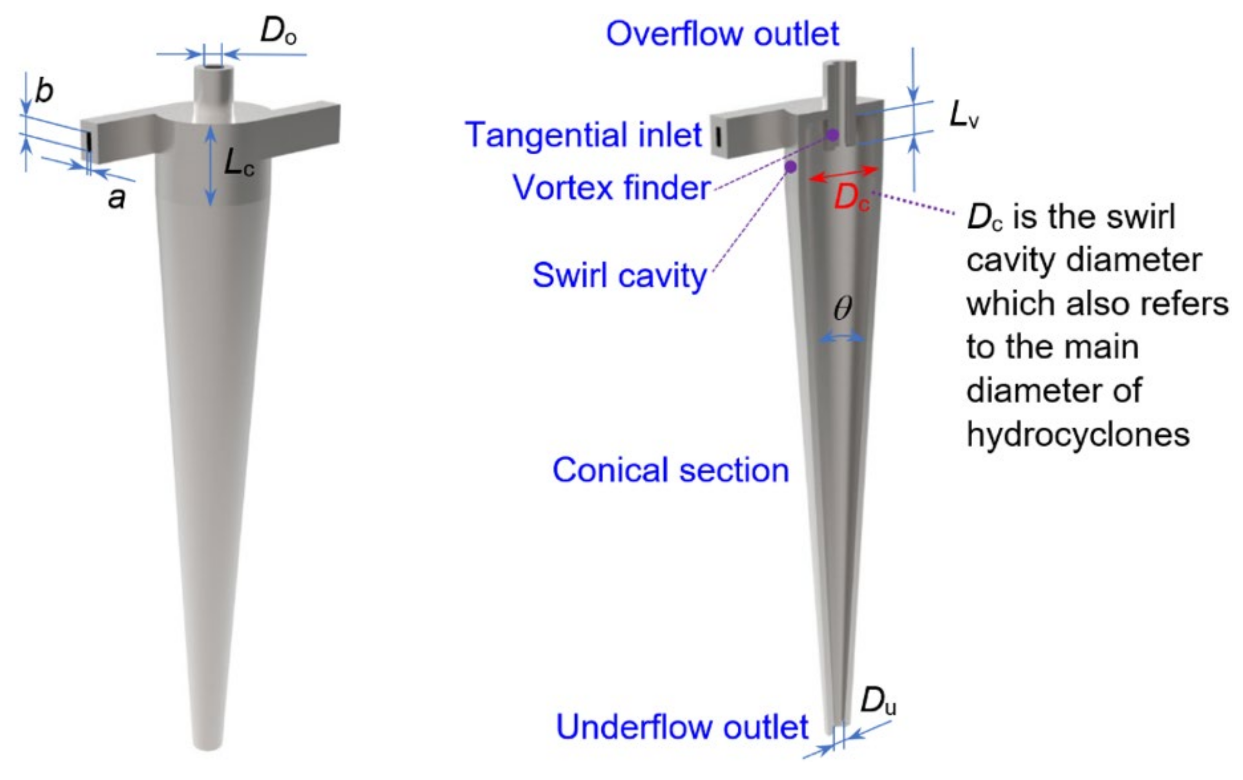
2.1.1. Structural Parameters of Hydrocyclone

The optimal structural parameters of the hydrocyclone vary depending on the type of media to be separated. In this subsection, the discrete phase is oil droplets with a density less than that of water. Yang et al. [33] used a hydrocyclone to separate discrete phases (whose density is less than water) and achieved satisfying separation efficiency; therefore, the structural parameters of the hydrocyclone herein are based on Yang et al. [33]. The fluid domain structure of hydrocyclone and specific size ratios are shown in Figure 3 and Table 1. According to the size ratio in Table 1, three hydrocyclones with the same structural type but different main diameters Dc were designed, including hydrocyclones with Dc = 20 mm (MHC), 30 mm (MHC), and 40 mm (CHC), respectively.

2.1.2. Preprocessing of Simulations

The fluid domains of three hydrocyclones were meshed. Figure 4a shows the meshing results of one of the hydrocyclones. As shown, the hexahedral meshes were applied with locally refined grids for the regions near the wall and swirl chambers (having high turbulence intensity). Through the mesh quality inspection, it can be found that the skewness (Equisize skew) of all mesh elements is less than 0.51, indicating that the quality of mesh elements is favorable. The method, quantity and density of meshing for the three hydrocyclones are the same, to avoid the simulation error caused by the mesh difference. Six levels (280,000, 380,000, 480,000, 580,000, 680,000, and 780,000) of mesh cell numbers were selected and the mesh independence test was carried out with the pressure loss of underflow outlet as the object. The mesh-independent test results show (Figure 4b) that, when the number of meshes reaches 580,000, the pressure loss tends to be stable. Therefore, the number of meshes selected in subsequent simulations is 580,000 considering the time-saving and computational resources.

2.1.3. Simulation Method and Settings

Numerical simulations of three hydrocyclones were carried out by using CFD software FLUENT, containing simulations under different oil droplet sizes and feed oil concentrations (OC). The Eulerian multiphase flow model was used during simulations. The impact of collisions between discrete phases is ignored in the simulation process, due to the low concentration of discrete phases to be separated. Regarding the turbulence model, Wang et al. [34] conducted a comprehensive analysis of the pros and cons of various turbulence models for the swirling flow field. At present, the Reynolds Stress Model (RSM) has been widely recognized and applied to simulate the continuous phase flow field [35,36]. This is because the RSM model completely abandons the eddy-viscosity assumption, which is consistent with the strongly swirling turbulent motion in the hydrocyclone. The exact transport equations for the transport of the Reynolds stresses, ρ u i u j ¯ were written as Equation (1) [36]. Therefore, based on research experience [23,37,38,39,40], the RSM model was selected in this manuscript. The velocity inlet and outflow were selected as the hydrocyclone’s feed and outlet boundary type, respectively. Since the density of the oil is smaller than water, the split ratio Rf for oil-water separation refers to the ratio of flow rate from overflow to feed, set to 35%. It must be ensured that the feed velocity and split ratio of each hydrocyclone are the same and unchanged during the simulation process. The wall slip can affect the flow characteristics of the fluid around the wall area, especially in high viscosity fluid [41,42,43]. However, for hydrocyclone separation, the water is the main phase whose viscosity is relatively low, and the fluid in hydrocyclones maintains a high rotation velocity; therefore, the wall slip effect can be ignored. Considerable studies [44,45,46,47] have selected no-slip for wall boundary during the simulation. The no-slip condition was also selected in this manuscript. The simulation accuracy was set to 10−6.
t ρ u i u j ¯ + x k ρ u k u i u j ¯ = x k ρ u i u j u k ¯ + ρ ( δ k j u i + δ i k u j ) ¯ + x k μ x k u i u j ¯ ρ u i u k ¯ u j x k + u j u k ¯ u i x k ρ β g i u j θ ¯ + g j u i θ ¯ + ρ u i x j + u j x i 2 μ u i x k u j x k ¯ 2 ρ Ω k u j u m ¯ ε i k m + u i u m ¯ ε j k m
where,   t ρ u i u j ¯ is the local time derivative, x k ρ u k u i u j ¯ is the convection, x k ρ u i u j u k ¯ + ρ ( δ k j u i + δ i k u j ) ¯ refers to the turbulent diffusion, x k μ x k ( u i u j ¯ ) means the molecular diffusion, ρ u i u k ¯ u j x k + u j u k ¯ u i x k represents the stress production, ρ β g i u j θ ¯ + g j u i θ ¯ means the buoyancy production, ρ u i x j + u j x i is the pressure strain, 2 μ u i x k u j x k ¯ is the dissipation, and 2 ρ Ω k u j u m ¯ ε i k m + u i u m ¯ ε j k m refers to production by system rotation.
The physical properties of the oil phase in the simulation process are shown in Table 2. Two kinds of feed OC studies were carried out. Among them, when the total OC was 5%, the respective concentration distributions of oil droplets with different sizes in the mixed liquid are shown in Figure 5, which belong to a normal distribution. When feed OC is 10%, the concentrations of oil droplets with different sizes are twice that of 5%. The grade separation efficiency (GSE) was used in this study, which is defined as the total separation efficiency of particles/droplets with a certain size in feed liquid, and the calculation of total separation efficiency is shown in Equation (2) [48].
E t = M o M i = 1 1 R f C d C i
where Mi and Mo are the oil mass from feed and overflow outlet; Rf is the split ratio (flow rate from overflow to feed); Ci and Cd represent the OC from feed and underflow outlet.

2.2. Simulation of Silica Particle and Water Separation

For silica particle and water separation, the appropriate structural parameters of hydrocyclone are different from that of oil-water separation [49], The structural parameter proportions proposed by Bradley [50] can obtain a smaller cutting size d50 (the particle size value when the separation efficiency reaches 50%) in the application of solid–liquid separation, i.e., it is more advantageous for the separation of small-sized particles, so Bradley’s structure is widely used [51,52]. The structural parameter ratios of hydrocyclones for silica particle and water separation were also based on Bradley’s structure. Table 3 presents the detailed structural parameter ratios of hydrocyclones. Three hydrocyclones with main diameter Dc = 2.5 mm (MHC), Dc = 10 mm (MHC), Dc = 40 mm (CHC) were utilized for simulation. The meshing rules for the three hydrocyclones are the same as those in Section 2.1.2, and the number and density of mesh elements used in the three hydrocyclones are also the same to avoid simulation errors caused by meshing. In addition, the multiphase model, turbulence model and boundary types, etc., during the simulations are similar to that of Section 2.1.2. The physical properties of the medium are shown in Table 4.

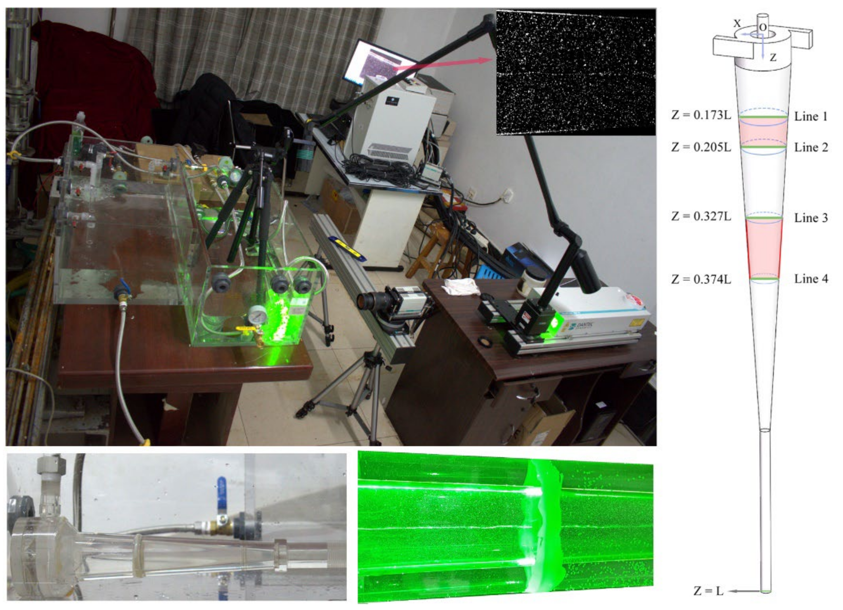
2.3. Particle Image Velocimetry (PIV) Experiment

Particle image velocimetry (PIV) experiments were implemented to verify the accuracy of simulations. PIV can obtain the flow information for the hydrocyclone in a certain section under an instantaneous condition so that researchers can grasp the complex flow characteristics in the hydrocyclone. The principle of PIV technology can be simply summarized as follows: measuring the displacement of the tracer particles within a certain time interval to measure the average velocity of the particles; the particle velocity represents the velocity of the fluid here.
Taking the hydrocyclone for silica–water separation as the example, the test and analysis of the axial velocity in the hydrocyclone were carried out. The detail experimental process and the locations for the hydrocyclone to be tested are shown in Figure 6. The accuracy of the simulation method in this study can be verified by comparing the tested and simulated values of the axial velocity on line 1, line 2, line 3 and line 4.

3. Results and Discussion

3.1. Oil-Water Separation

For oil-water separation through three different hydrocyclones, the oil concentration (OC) from underflow outlet, the grade separation efficiency and pressure loss were chosen as the metrics to evaluate the separation performance.

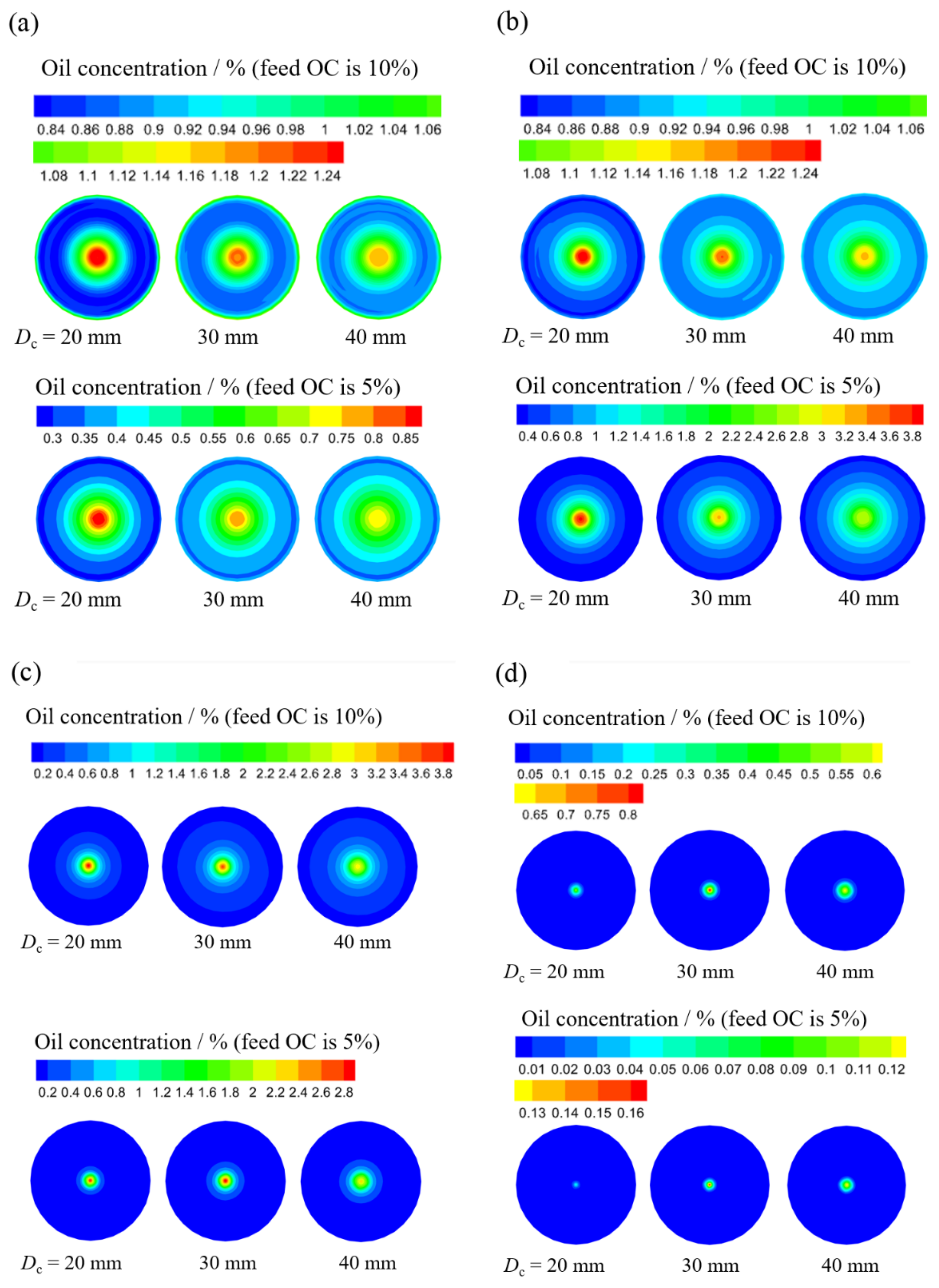
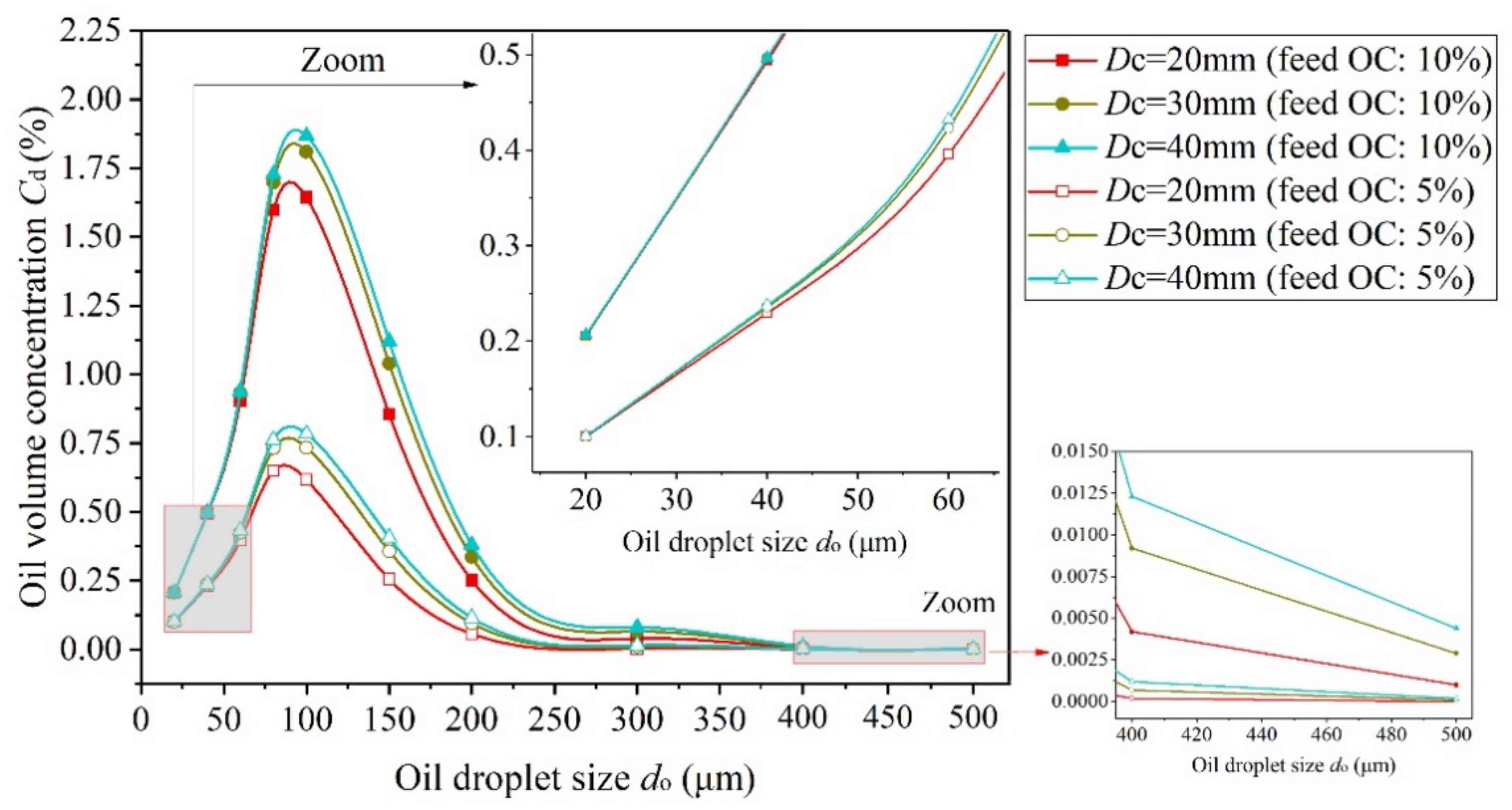
3.1.1. Oil Concentration Analysis

The OC of the underflow outlet is one of the important separation performance metrics for the oil-water separation hydrocyclone [53]. Under the same conditions, the smaller the underflow OC, the higher the separation efficiency. Herein, for two different feed OCs (5% and 10%), the OC distributions at underflow outlet were compared and analyzed, after the oil droplets with different particle sizes (exampled by 60 μm, 100 μm, 200 μm and 400 μm,) were separated by MHC (Dc = 20 mm and 30 mm) and CHC (Dc = 40 mm), respectively. As shown in Figure 7, it can be observed that: (1) the OC at underflow outlet increases as feed OC increases, which means a reduction in separation efficiency according to Equation (2); (2) with the decrease of the main diameter Dc of hydrocyclone, the OC near the center area of underflow outlet showed a gradually increasing trend at both feed OCs; whereas the OC at the area far from the center showed a gradually decreasing trend, which indicated that the oil droplets are easier to move to the vicinity of the axis and gather to form a central-high-concentration area, as the separation occurred in MHC. However, when the oil droplet size reaches 400 μm, the OC at the center of the underflow outlet shows a trend, first increasing then decreasing, with the increase of hydrocyclone’s Dc. This is because almost all the 400 μm oil droplets can be successfully separated by MHC with Dc = 20 mm and only a few oil droplets gather in the center of underflow outlet, which cannot form a high-concentration area. (3) Comparing Figure 7a–d, it can be concluded that, with the increase of the oil droplet size, the oil droplets in all three hydrocyclones are more likely to move to the center area. This means that the large oil droplets can be efficiently separated in both MHC and CHC.
To quantify the average OC value at the underflow outlet for the three hydrocyclones, Figure 8 provides the average OC curves under various droplet sizes when feed OC is 5% and 10%. From Figure 8, the OC average values show a decreasing trend as Dc increases under the same droplet size. When droplet sizes are in the range of 20–60 μm and 400–500 μm, the OC decreasing trend is relatively weak, which means: (1) MHC has no obvious effect on enhancing the separation efficiency of oil droplets with 20–60 μm; (2) for large-size oil droplets (400–500 μm), both CHC and MHC can achieve high-efficiency separation, i.e., the average OC values at the underflow are close to 0; while, when droplet size is in the range of 100–300 μm, especially in the cases of 100 μm and 150 μm, the OC of MHC is significantly lower than that of MHC, and the smaller the Dc, the lower the OC at underflow outlet. Additionally, the decreasing amplitude for OC equaling 5% is higher than that for the case of 10%, which indicates that the separation performance enhancement of MHC is more significant when feed OC is low.

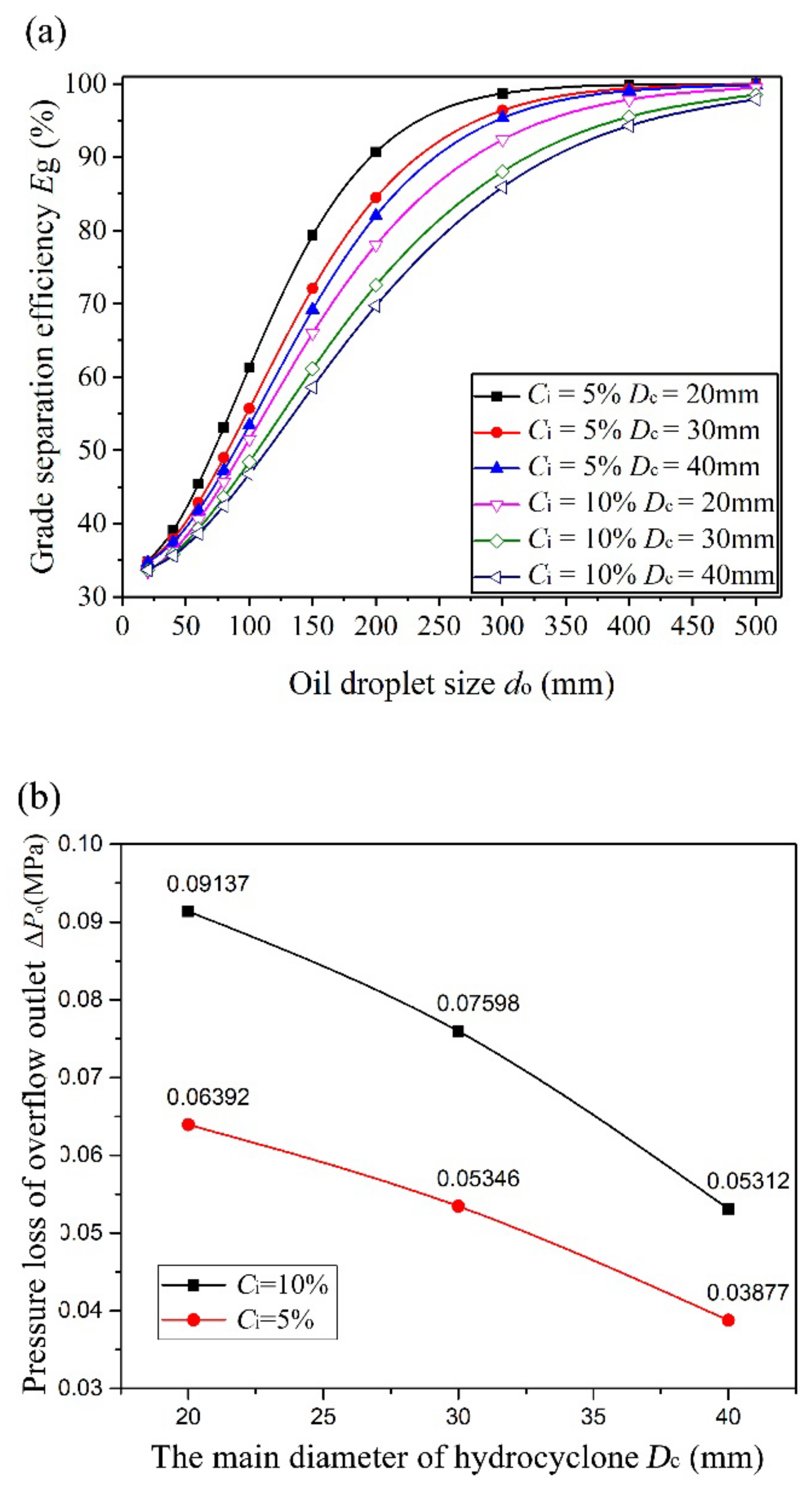
3.1.2. Grade Separation Efficiency and Pressure Loss

Figure 9a shows the grade separation efficiency (GSE) distribution curves of two MHCs and a CHC. It can be seen that the GSE variation trends under different conditions are basically the same for the three hydrocyclones: as the oil droplet size increases, GSE increases slowly, increases rapidly, and then continues to increase slowly and gradually remains unchanged, appearing as an “S” shape. The increase of feed OC value (from 5% to 10%) results in the decrease of GSE, and this observation is not obvious when droplet size is 20 μm and 500 μm. Therefore, for the feed liquid with high OC, high-efficiency separation could be achieved by adding a coalescing device before hydrocyclone separation.
Comparing the GSE of the three hydrocyclones (Figure 9a), it also can be found that: (1) As the main diameter (Dc) of the hydrocyclone decreases, the GSE gradually increases, which is applicable to all droplet size values, and this increasing trend does not change with the difference in feed OC; (2) When droplet size is large (400–500 μm) or small (20–60 μm), the enhancement of GSE by MHC is not obvious, which means that the separation efficiency of oil droplets that are too small cannot be significantly improved despite the use of an MHC. Similarly, when oil droplet size is too large, the enhancement of GSE is also not obvious, since CHC can reach a high separation efficiency for large oil droplets. (3) For oil droplet size of 60–300 μm, the enhancement effect of MHC on GSE is significantly higher than that of oil droplets with other size ranges; the maximum enhancement of GSE reaches 10%.
Figure 9b offers the variation rules of the overflow pressure loss for three different hydrocyclones, and two different feed OCs were analyzed. Figure 9b shows that the pressure loss corresponding to high feed OC is apparently greater than that of low feed OC. This is because the high feed OC value increases the viscosity of the oil-water mixed liquid, causing the movement of liquid to be more difficult, and the higher energy required at the same feed velocity, thus resulting in a greater pressure loss. It can also be observed that with the increase of Dc, the pressure loss gradually decreases, indicating that more energy consumption is needed for MHC under the same feed velocity.

3.2. Silica Particle and Water Separation

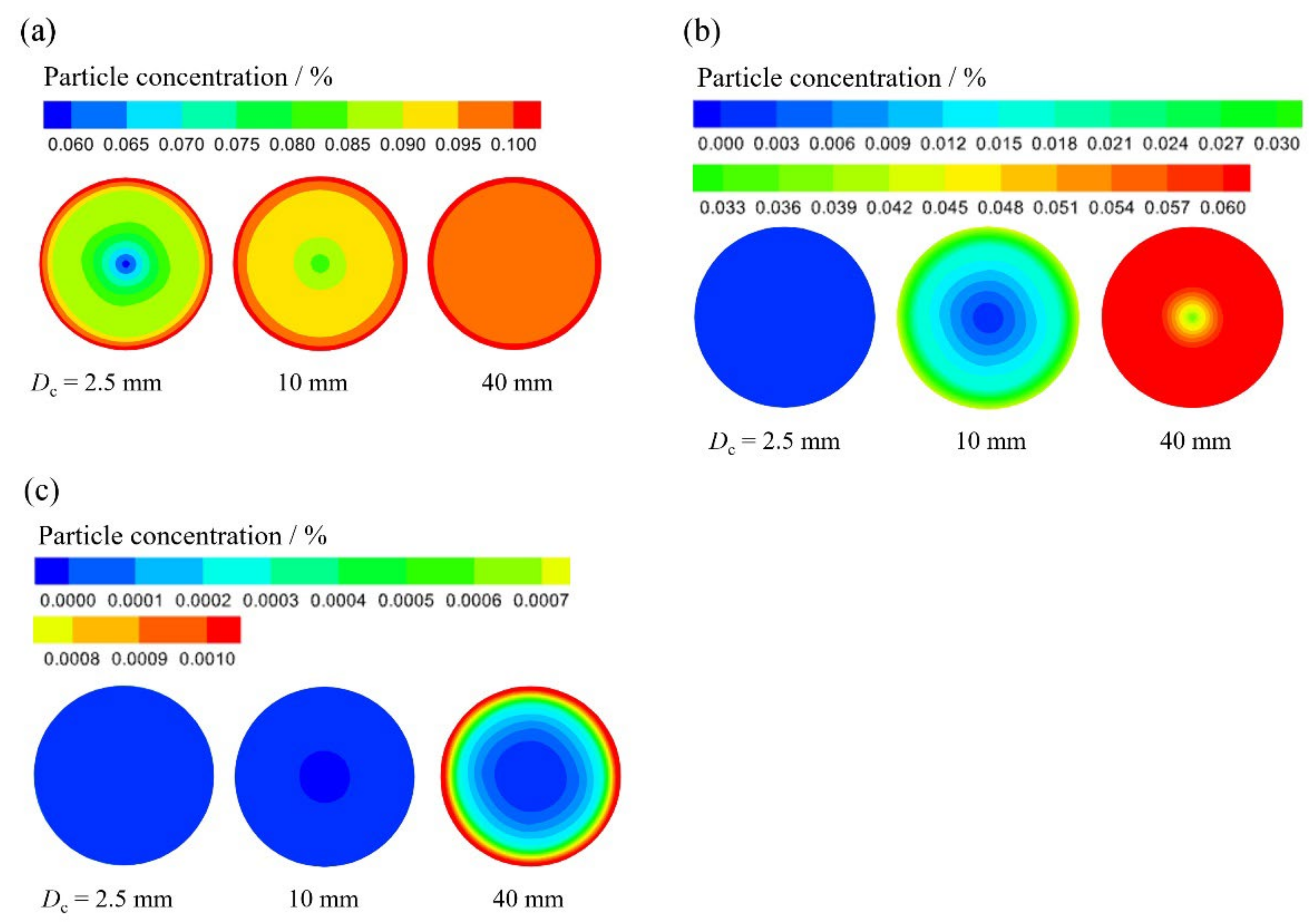
3.2.1. Particle Concentration Distribution

Regarding silica particle and water separation, the separation goal is to ensure that more particles are smoothly discharged from the underflow outlet of hydrocyclone. Therefore, the particle concentration (PC) at the overflow outlet was taken as one of the important separation performance metrics for silica–water separation, and the smaller the PC value at overflow outlet, the better the separation efficiency. Figure 10a–c show the PC distribution at overflow outlet of three different hydrocyclones, and the representative particle sizes (dp) of 5 μm, 20 μm, and 60 μm were selected to carry out the analysis. As the particle size increases, the PC at the overflow outlet of all three hydrocyclones decreases significantly. Combining the legends of the three particle sizes (corresponding to Figure 10a–c), the maximum value of PC decreases from 0.1% (dp = 5 μm) to 0.001% (dp = 60 μm). Furthermore, the PC distribution shows a gradually increasing trend along the direction from the center of the wall of overflow outlet. This is because the silica particles with higher density than water tend to move in the direction opposite to the center of the hydrocyclone under the action of centrifugal force.
Under the condition of the same particle size, the PC at overflow outlet decreases obviously as the decrease of the main diameter Dc of hydrocyclone (from Dc = 40 mm to 2.5 mm), especially for the particles of 20 μm and 60 μm. For 5 μm particles, the decrease of PC at overflow outlet is relatively low with the decrease of Dc. When the particle size is 5 μm, the PC value at CHC’s (Dc = 40 mm) overflow outlet is almost maintained in the range of 0.095–0.1%, which is basically the same as the feed particle concentration at 0.1% (see Table 4). This implies that the CHC has no separation effect on the particles of 5 μm, while the PC value of MHC with Dc = 2.5 mm is between 0.07% and 0.09% in most areas of overflow outlet, which demonstrates MHC is still effective for the separation of 5 μm silica particles.
From Figure 10a–c, the overflow outlet of MHC (Dc = 2.5 mm) has almost no particles when the particle size reaches 20 μm. Therefore, Table 5 gives the average PV values of the three kinds of particle sizes below or equal 20 μm at overflow outlet. Table 5 shows that the overflow’s PC for all three hydrocyclones gradually decreases with the increase of particle size, and when the particle size reaches 20 μm, PC of MHC (Dc = 2.5 mm) was only 0.000634%, well below the feed value of 0.1%.

3.2.2. Grade Separation Efficiency and Pressure Loss

Figure 11a presents the GSE curves for three hydrocyclones. The variation trend of GSE curves is similar to the oil–water separation in the previous section (see Figure 9), i.e., GSE gradually increases to the maximum value and then remains unchanged with the increase of particle size. When GSE of hydrocyclone with Dc = 2.5 mm, 10 mm and 40 mm approached 100%, the corresponding particle sizes are 20 μm, 40 μm and 60 μm, respectively. When the particle size dp equals 5 μm, the GSEs of all three hydrocyclones are at a low level, but the GSE of the MHC with Dc = 2.5 mm increased by 23% compared with CHC. The CHC achieves a separation efficiency of about 35% for 5 μm particles, which is caused by the bypass effect (i.e., split ratio Rf = 35%). It can also be observed from Figure 11a that the enhancement effect of GSE of MHC is the most obvious when particle size is in the range of 10–40 μm. The particle size range of significant enhancement here is different from the oil–water separation (60–300 μm) in Section 3.1, because the density difference between oil and water is significantly smaller than that between particles and water. Additionally, the higher viscosity of the oil phase also causes the oil–water separation efficiency to be inferior to silica–water separation. Comparing the three hydrocyclones, the cutting particle size d50 for both MHCs (Dc = 2.5 mm and 10 mm) is between 5 and 10 μm, while that of the CHC is between 10–20 μm. MHC can realize a smaller d50.
Figure 11b offers the variation trend of pressure loss at the overflow outlet. With the increase of Dc, the pressure loss showed a trend of decreasing rapidly at first and then decreasing slowly. Compared with CHC, the pressure loss of MHC (Dc = 2.5 mm) is increased by 6.36%.
The grade efficiency curves for both oil–water and silica–water separation expressed a similar “S” shape. This variation trend is the same as the typical grade efficiency curve of hydrocyclones. Bai et al. [54], Nenu et al. [55], Medronho et al. [39] and Abdollahzadeh et al. [56] all obtained similar grade efficiency changing trends by MHC separation.

3.3. Analysis and Discussion of Efficiency Enhancement of MHC

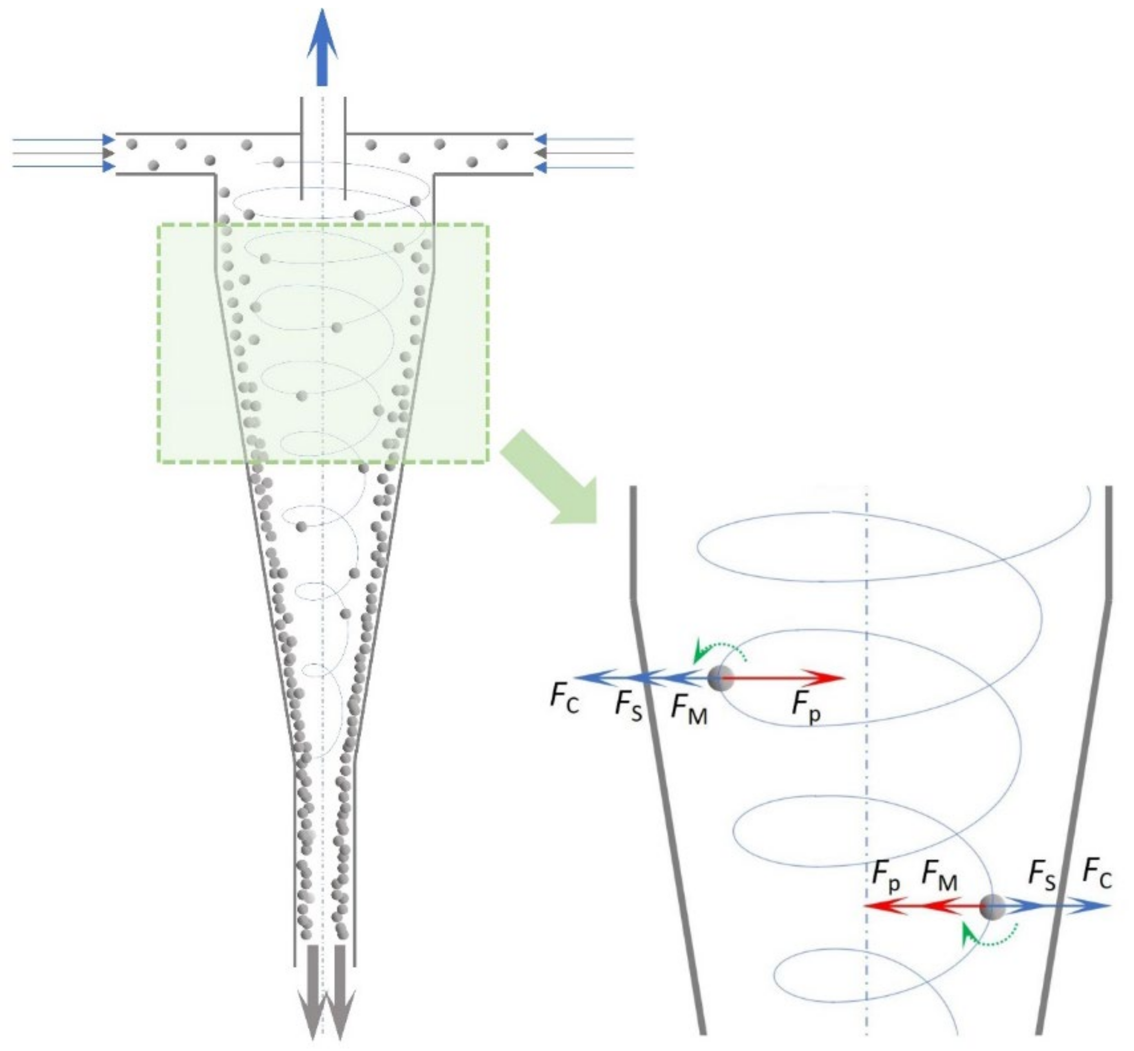
3.3.1. Efficiency Enhancement Analysis

Hydrocyclone uses the centrifugal force difference between the discrete phase and the continuous phase during the rotating motion of the mixed liquid and makes the relative radial velocity between them in otfrt to achieve rapid separation. Therefore, the radial resultant force of particles (taking the particles heavier than water as the example) during the movement determines whether they can smoothly move to the wall of the hydrocyclone and be separated successfully. The radial forces experienced by particles in the hydrocyclone include the centrifugal force and the radial pressure gradient force, Stokes resistance exerted by water on the particles and Magnus force generated by particle autorotation, as shown in Figure 12. According to Figure 12, the expression of the radial resultant force of particles can be obtained, as shown in Equation (3) [57]. Table 6 provides the calculation formulas and causes of these radial forces.
F = FpFCFS ± FM
where, mp is the mass of the particle; a is the centrifugal acceleration of particle; x refers to the particle size; ρw and ρp are the densities of water and particles, respectively; vt represents the tangential velocity; r is the radial distance from the axis of the hydrocyclone; μ represents the dynamic viscosity of the mixed liquid; vr is the relative radial velocity of the particle and the continuous phase; k is a constant; ω is the particle angular velocity.
Among the radial forces, the radial pressure gradient force Fp and the centrifugal force FC play a major role during separation, and the difference ΔF between Fp and FC determines the speed of the particles moving toward the hydrocyclone’s inner wall. The greater the ΔF, the greater the acceleration of the particles moving toward the wall area. Although the type of radial force in MHC is similar to that of CHC, the radial resultant force is significantly different from that of CHC owing to the MHC’s smaller radial space. The difference between Fp and FC is analyzed below.
The difference ΔF1 between Fp1 and FC1 of CHC is shown in Equation (4):
Δ F 1 = F P 1 F C 1 = π 6 x 1 3 v t 1 2 r 1 ( ρ w ρ o )
The difference ΔF2 between Fp2 and FC2 of CHC is shown in Equation (5):
Δ F 2 = F P 2 F C 2 = π 6 x 2 3 v t 2 2 r 2 ( ρ w ρ o )
Assuming that the feed velocity, the particle size (x1 = x2) and the tangential velocity at the particle location are the same (vt1 = vt2), according to Equations (4) and (5), it can be calculated that ΔF2 is larger than ΔF1 since the radial space of MHC is smaller than that of CHC. That is, the radial resultant force on the particles in MHC is greater, therefore, particles are easier to move to the inner wall area of MHC and be successfully separated. Similarly, it can also be concluded that the discrete phase with less density than water is more likely to move to the center of MHC than CHC.

3.3.2. Discussion

From the discussion and analysis in Section 3.1 and Section 3.2, the separation efficiency of MHC for both oil droplets (lighter than water) and silica particles (heavier than water) is better than that of CHC under the same feed velocity. With the smaller density difference between oil and water and the higher viscosity of oil phase, there is an obvious difference in the optimal particle size range where the separation efficiency is significantly enhanced by MHC for different types of discrete phases. In addition, the pressure loss of MHC is higher than CHC under the same feed velocity. Liu et al. [48] carried out research on the separation performance of hydrocyclone with two different Dc under the same feed pressure and kept the overflow and underflow outlets toward the air, i.e., the pressure loss of the two hydrocyclone is the same. Results also show that a hydrocyclone with smaller Dc can obtain a higher separation efficiency.
In practical applications, such as oil–water separation in the produced fluid from the offshore platform, it is necessary to design multiple mini hydrocyclones in parallel to ensure the requirements for both high-efficiency and high flow rate [29,58,59]. The number of MHCs in the parallel system depends on the feed flow rate on site. When the particle size distribution in the mixed liquid is wide (e.g., from a few microns to thousands of microns), a feasible solution can be obtained via the research of this paper: the mixed liquid is pre-separated with a CHC to separate the large size particles/droplet, while the fine particles/droplets that are difficult to separate enter the MHC for secondary separation along with the water phase. This solution could ensure a high separation efficient while avoiding the problem of high energy consumption caused by the use of MHC alone, also reducing the risk of clogging at the inlet or outlet of MHC by large particles.

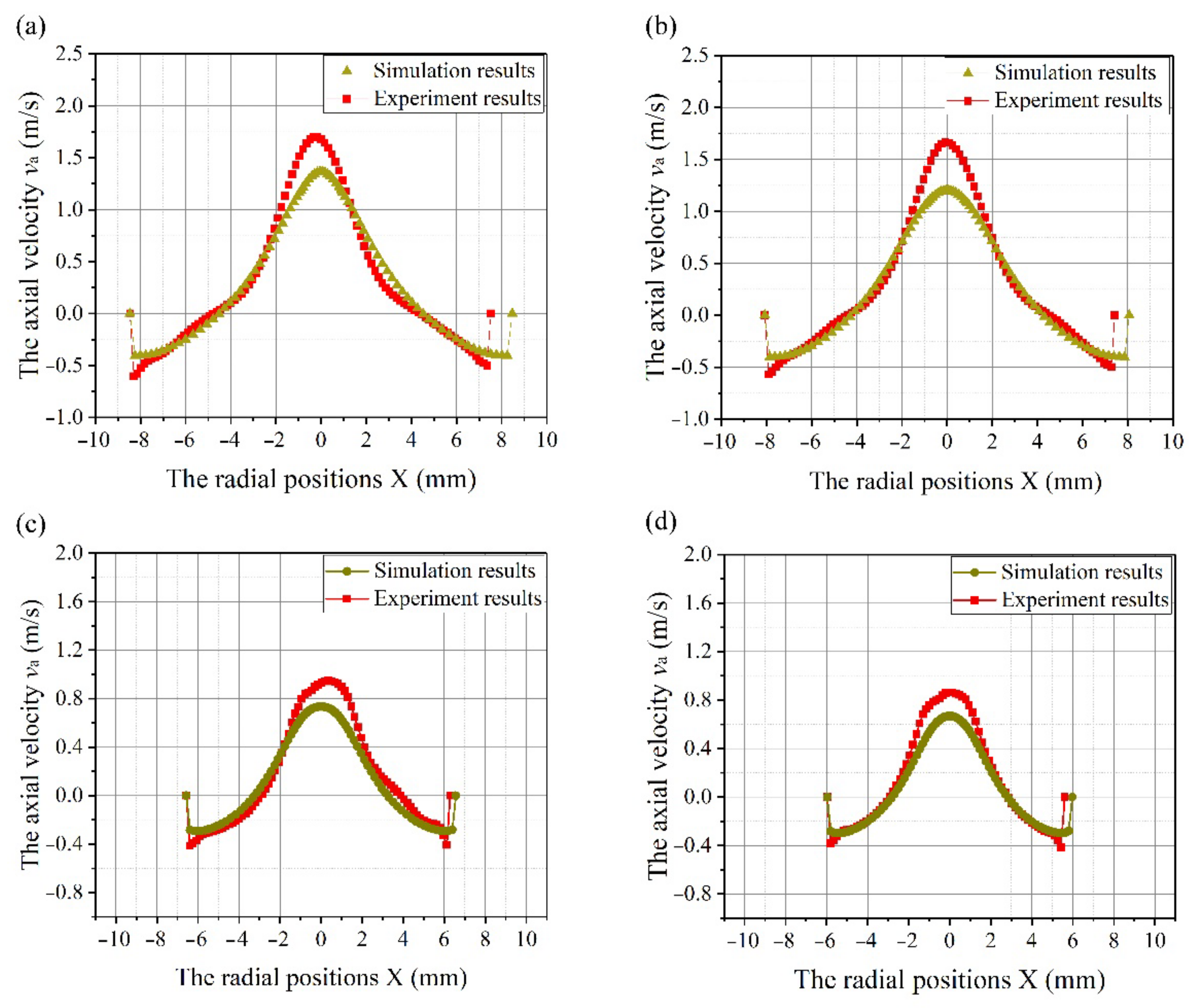
3.4. Verification of the Accuracy of Numerical Simulations

The axial velocities (va) at line 1–line 4 (the detailed locations are shown in Figure 6) were obtained by PIV experiment. Figure 13a–d present the comparisons of axial velocities between simulation and experiment, to verify the accuracy of simulations in this study. Figure 13 shows that the variation trends of the axial velocity curves obtained under the simulated and experimental conditions on all four lines are the same, and the simulated values are highly consistent with the experimental values, especially at locations far from the center of hydrocyclone, which verifies the accuracy of the numerical simulations. The variation trends of axial velocity are similar to Fan et al. [30], Song et al. [60] and He et al. [61], who all utilized a PIV device to test the axial velocity in hydrocyclones.
It is worth noting that the experimental values of axial velocity near the hydrocyclone’s center area are larger than the simulated values. This is caused by the central air-core created inside the hydrocyclone during the experiment: due to the existence of a certain amount of micro-bubbles and dissolved gas in the water phase, after the mixed phase enters the hydrocyclone, an air-core is formed on the central axis, which occupies the position that should belong to the water. Assuming that there is no air-core in the axis area and it is all water phase, since the air viscosity is much smaller than that of the water phase, the axial velocity of the water phase with higher viscosity at the axis area is smaller than the axial velocity of the air at this area when air-core exists. Therefore, the greater air velocity will drive the velocity of the water phase near the air-core.

4. Conclusions

It is of great significance for the efficient and precise application of the mini hydrocyclone (MHC) to clarify the adaptability of MHC to the separation of different types of media. The current study evaluated the efficiency enhancement of MHC by conducting research on the separation performance of different types of media based on three hydrocyclones. The following conclusions were obtained.
(1)
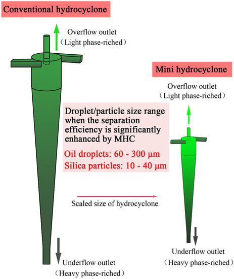
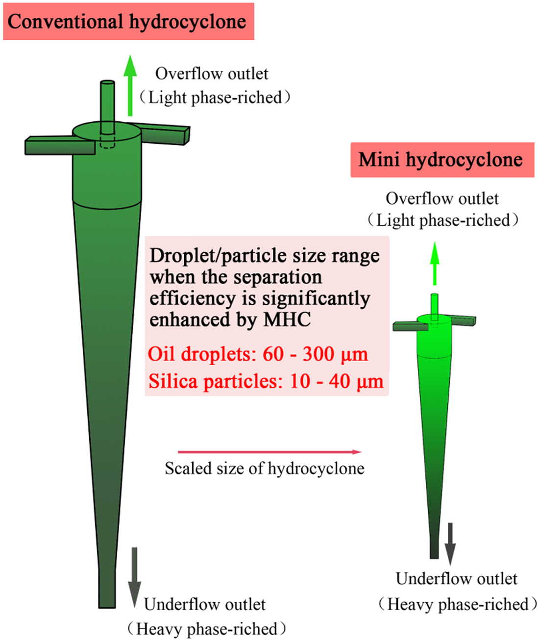
The separation performance of the oil–water separation by hydrocyclone with different main diameters (Dc) was studied. Results show that the separation efficiency of MHC is higher than that of the conventional hydrocyclone (CHC) under the same feed flow velocity, and it is suitable for the situation of both high and low feed oil concentrations. When the oil droplet size is between 60 and 300 μm, the effect of efficiency enhancement of MHC is more obvious. For the oil droplet size below 20 μm and over 400 μm, the enhancement effect of MHC on the separation efficiency is not significant.
(2)
Through the research on silica–water separation, the corresponding particle size range is 10–40 μm when the separation efficiency of MHC is significantly enhanced compared with CHC, which is lower than the optimal particle size range for oil–water separation. When the particle size is larger than 60 μm, the separation efficiency for MHC is comparable to that of MHC. CHC cannot separate particles as small as 5 μm, while MHC still provides separation. Additionally, the efficiency enhancement of MHCs was explained from the perspective of force analysis of discrete phase in MHC and CHC.
(3)
The pressure loss of MHC is higher than that of CHC for both oil–water and silica–water separations. Connecting the CHC with MHC in series could ensure the high separation efficiency of particles while avoiding the high energy consumption and clogging problems caused by using the MHC alone.

Nomenclature or Abbreviations

Nomenclature
a and bThe height and width of the tangential inlet of hydrocyclone
d50Cut size, means the particle/droplet size when the grade efficiency equals 50%
doOil droplet size
dpParticle size
CiFeed concentration
DcThe main diameter of hydrocyclone
DoDiameter of overflow outlet
DuDiameter of underflow outlet
EgGrad separation efficiency
LcLength of the cylindrical section
LdLength of underflow pipe
LvLength of vortex finder
ReReynolds number
RfSplit ratio
θAngle of cone section
ρoOil density
ηoOil viscosity
Abbreviations
CHCConventional hydrocyclone
GSEGrade separation efficiency
MHCMini hydrocyclone
OCOil concentration
PCParticle concentration
PIVParticle image velocimetry
PWProduced water
RSMReynolds stress model

Author Contributions

Conceptualization, L.L. and L.Z.; methodology, L.L.; software, L.L. and S.Z.; validation, L.L. and S.Z.; formal analysis, L.L. and Y.W.; investigation, X.H.; resources, M.S.; data curation, L.L. and Z.L.; writing—original draft preparation, L.L.; writing—review and editing, L.Z.; visualization, Y.W.; supervision, L.Z.; project administration, L.Z. All authors have read and agreed to the published version of the manuscript.

Funding

This research was funded by the National Key Research and Development Project of China [grant number 2018YFE0196000]; The Joint Funds of the National Natural Science Foundation of China (Key program) [grant number U21A20104]; The Natural Science Foundation (Key projects) of Heilongjiang Province, China [grant number ZD2020E001]; The Supporting Project for Longjiang Scholars of Northeast Petroleum University, China [grant number lj201803].

Institutional Review Board Statement

Not applicable.

Informed Consent Statement

Not applicable.

Data Availability Statement

Not applicable.

Conflicts of Interest

The authors declare no conflict of interest.

References

  1. Qiu, R.; Li, Z.; Zhang, Q.; Yao, X.; Xie, S.; Liao, Q.; Wang, B. A Realistic and Integrated Model for Evaluating Offshore Oil Development. J. Mar. Sci. Eng. 2022, 10, 1155. [Google Scholar] [CrossRef]
  2. Yacovitch, T.I.; Daube, C.; Herndon, S.C. Methane Emissions from Offshore Oil and Gas Platforms in the Gulf of Mexico. Environ. Sci. Technol. 2020, 54, 3530–3538. [Google Scholar] [CrossRef] [PubMed]
  3. Liu, Y.; Lu, H.; Li, Y.; Xu, H.; Pan, Z.; Dai, P.; Wang, H.; Yang, Q. A Review of Treatment Technologies for Produced Water in Offshore Oil and Gas Fields. Sci. Total Environ. 2021, 775, 145485. [Google Scholar] [CrossRef] [PubMed]
  4. Tanudjaja, H.J.; Hejase, C.A.; Tarabara, V.V.; Fane, A.G.; Chew, J.W. Membrane-Based Separation for Oily Wastewater: A Practical Perspective. Water Res. 2019, 156, 347–365. [Google Scholar] [CrossRef]
  5. Mccormack, P.; Jones, P.; Hetheridge, M.J.; Rowland, S.J. Analysis of Oilfield Produced Waters and Production Chemicals by Electrospray Ionisation Multi-Stage Mass Spectrometry (ESI-MSn). Water Res. 2001, 35, 3567–3578. [Google Scholar] [CrossRef]
  6. Jimenez, S.; Mico, M.M.; Arnaldos, M.; Medina, F.; Contreras, S. State of the Art of Produced Water Treatment. Chemosphere 2018, 192, 186–208. [Google Scholar] [CrossRef]
  7. Lu, H.; Liu, Y.-Q.; Cai, J.-B.; Xu, X.; Xie, L.-S.; Yang, Q.; Li, Y.-X.; Zhu, K. Treatment of Offshore Oily Produced Water: Research and Application of a Novel Fibrous Coalescence Technique. J. Pet. Sci. Eng. 2019, 178, 602–608. [Google Scholar] [CrossRef]
  8. Mousa, H.; Fahmy, H.; Ali, G.; Abdelhamid, H.; Ateia Ibrahim, M. Membranes for Oil/Water Separation: A Review. Adv. Mater. Interfaces 2022, 9, 2200557. [Google Scholar] [CrossRef]
  9. Mousa, H.M.; Fahmy, H.S.; Abouzeid, R.; Abdel-Jaber, G.T.; Ali, W.Y. Polyvinylidene Fluoride-Cellulose Nanocrystals Hybrid Nanofiber Membrane for Energy Harvesting and Oil-Water Separation Applications. Mater. Lett. 2022, 306, 130965. [Google Scholar] [CrossRef]
  10. Mousa, H.M.; Hamdy, M.; Yassin, M.A.; El-Sayed Seleman, M.M.; Abdel-Jaber, G.T. Characterization of Nanofiber Composite Membrane for High Water Flux and Antibacterial Properties. Colloids Surf. A Physicochem. Eng. Asp. 2022, 651, 129655. [Google Scholar] [CrossRef]
  11. Mousa, H.M.; Alfadhel, H.; Ateia, M.; Abdel-Jaber, G.T.; Gomaa, A.A. Polysulfone-Iron Acetate/Polyamide Nanocomposite Membrane for Oil-Water Separation. Environ. Nanotechnol. Monit. Manag. 2020, 14, 100314. [Google Scholar] [CrossRef]
  12. Pedersen, S.; Bram, M.V. The Impact of Riser-Induced Slugs on the Downstream Deoiling Efficiency. J. Mar. Sci. Eng. 2021, 9, 391. [Google Scholar] [CrossRef]
  13. Mognon, J.L.; da Silva, J.M.; Bicalho, I.C.; Ataíde, C.H.; Duarte, C.R. Modular Mini-Hydrocyclone Desilter Type of 30 Mm: An Experimental and Optimization Study. J. Pet. Sci. Eng. 2015, 129, 145–152. [Google Scholar] [CrossRef]
  14. Mognon, J.L.; Bicalho, I.C.; Ataíde, C.H. Mini-Hydrocyclones Application in the Reduction of the Total Oil-Grease (TOG) in a Prepared Sample of Produced Water. Sep. Sci. Technol. 2016, 51, 370–379. [Google Scholar] [CrossRef]
  15. Huang, Y.; Li, J.-P.; Zhang, Y.-H.; Wang, H.-L. High-Speed Particle Rotation for Coating Oil Removal by Hydrocyclone. Sep. Purif. Technol. 2017, 177, 263–271. [Google Scholar] [CrossRef] [Green Version]
  16. Mognon, J.L.; da Silva, J.M.; Bicalho, I.C.; Ataíde, C.H.; Duarte, C.R. Mini-Hydrocyclones Applied to the Removal of Solids from Non-Newtonian Fluids and Analysis of the Scale-Up Effect. J. Pet. Sci. Eng. 2016, 146, 255–263. [Google Scholar] [CrossRef]
  17. Vakamalla, T.R.; Mangadoddy, N. Numerical Simulation of Industrial Hydrocyclones Performance: Role of Turbulence Modelling. Sep. Purif. Technol. 2017, 176, 23–39. [Google Scholar] [CrossRef]
  18. Chu, L.Y.; Chen, W.M.; Lee, X.Z. Effect of Structural Modification on Hydrocyclone Performance. Sep. Purif. Technol. 2000, 21, 71–86. [Google Scholar] [CrossRef]
  19. Zhao, L.; Li, Y.; Xu, B.; Jiang, M. Design and Numerical Simulation Analysis of an Integrative Gas-Liquid-Solid Separation Hydrocyclone. Chem. Eng. Technol. 2015, 38, 2146–2152. [Google Scholar] [CrossRef]
  20. Abdollahzadeh, L.; Mazraeno, M.S.; Hosseini, S.N.; Fazlali, A.; Soury, E.; Habibian, M.; Khatami, M. Numerical and Experimental Biomass Separation from Fermentation Process ByMinihydrocyclones. Chem. Eng. Technol. 2021, 44, 23–30. [Google Scholar] [CrossRef]
  21. Kyriakidis, Y.N.; Silva, D.O.; Barrozo, M.A.S.; Vieira, L.G.M. Effect of Variables Related to the Separation Performance of a Hydrocyclone with Unprecedented Geometric Relationships. Powder Technol. 2018, 338, 645–653. [Google Scholar] [CrossRef]
  22. Motin, A.; Tarabara, V.V.; Petty, C.A.; Bénard, A. Hydrodynamics within Flooded Hydrocyclones during Excursion in the Feed Rate: Understanding of Turndown Ratio. Sep. Purif. Technol. 2017, 185, 41–53. [Google Scholar] [CrossRef]
  23. Shakeel Syed, M.; Rafeie, M.; Henderson, R.; Vandamme, D.; Asadnia, M.; Ebrahimi Warkiani, M. A 3D-Printed Mini-Hydrocyclone for High Throughput Particle Separation: Application to Primary Harvesting of Microalgae. Lab Chip 2017, 17, 2459–2469. [Google Scholar] [CrossRef] [PubMed]
  24. Zhao, L.; Jiang, M.; Wang, Y. Experimental Study of a Hydrocyclone under Cyclic Flow Conditions for Fine Particle Separation. Sep. Purif. Technol. 2008, 59, 183–189. [Google Scholar] [CrossRef]
  25. Endres, E.; Dueck, J.; Neesse, T. Hydrocyclone Classification of Particles in the Micron Range. Miner. Eng. 2012, 31, 42–45. [Google Scholar] [CrossRef]
  26. Xing, L.; Jiang, M.; Zhao, L.; Gao, J.; Liu, L. Design and Analysis of De-Oiling Coalescence Hydrocyclone. Sep. Sci. Technol. 2021, 57, 749–767. [Google Scholar] [CrossRef]
  27. Lv, W.J.; Huang, C.; Chen, J.Q.; Liu, H.L.; Wang, H.L. An Experimental Study of Flow Distribution and Separation Performance in a UU-Type Mini-Hydrocyclone Group. Sep. Purif. Technol. 2015, 150, 37–43. [Google Scholar] [CrossRef]
  28. He, F.; Zhang, Y.; Wang, J.; Yang, Q.; Wang, H.; Tan, Y. Flow Patterns in Mini-Hydrocyclones with Different Vortex Finder Depths. Chem. Eng. Technol. 2013, 36, 1935–1942. [Google Scholar] [CrossRef]
  29. Huang, C.; Wang, J.G.; Wang, J.Y.; Chen, C.; Wang, H.L. Pressure Drop and Flow Distribution in a Mini-Hydrocyclone Group: UU-Type Parallel Arrangement. Sep. Purif. Technol. 2013, 103, 139–150. [Google Scholar] [CrossRef]
  30. Fan, Y.; Wang, J.; Bai, Z.; Wang, J.; Wang, H. Experimental Investigation of Various Inlet Section Angles in Mini-Hydrocyclones Using Particle Imaging Velocimetry. Sep. Purif. Technol. 2015, 149, 156–164. [Google Scholar] [CrossRef]
  31. Pinto, R.C.V.; Medronho, R.A.; Castilho, L.R. Separation of CHO Cells Using Hydrocyclones. Cytotechnology 2008, 56, 57–67. [Google Scholar] [CrossRef] [PubMed] [Green Version]
  32. Moradinejad, S.; Vandamme, D.; Glover, C.M.; Seighalani, T.Z.; Zamyadi, A. Mini-Hydrocyclone Separation of Cyanobacterial and Green Algae: Impact on Cell Viability and Chlorine Consumption. Water 2019, 11, 1473. [Google Scholar] [CrossRef] [Green Version]
  33. Yang, Q.; Wang, H.; Wang, J.; Li, Z.; Liu, Y. The Coordinated Relationship between Vortex Finder Parameters and Performance of Hydrocyclones for Separating Light Dispersed Phase. Sep. Purif. Technol. 2011, 79, 310–320. [Google Scholar] [CrossRef]
  34. Wang, J.; Priestman, G.H.; Tippetts, J.R. Modelling of Strongly Swirling Flows in a Complex Geometry Using Unstructured Meshes. Int. J. Numer. Methods Heat Fluid Flow 2006, 16, 910–926. [Google Scholar] [CrossRef]
  35. Grady, S.A.; Wesson, G.D.; Abdullah, M.; Kalu, E.E. Prediction of 10-Mm Hydrocyclone Separation Efficiency Using Computational Fluid Dynamics. Filtr. Sep. 2003, 40, 41–46. [Google Scholar] [CrossRef]
  36. Liu, L.; Zhao, L.; Sun, Y.; Gao, S.; Jiang, M.; Jiang, M.; Rosso, D. Separation Performance of Hydrocyclones with Medium Rearrangement Internals. J. Environ. Chem. Eng. 2021, 9, 105642. [Google Scholar] [CrossRef]
  37. Hwang, K.-J.; Chou, S.-P. Designing Vortex Finder Structure for Improving the Particle Separation Efficiency of a Hydrocyclone. Sep. Purif. Technol. 2017, 172, 76–84. [Google Scholar] [CrossRef]
  38. Bai, Z.S.; Wang, H.L. Numerical Simulation of the Separating Performance of Hydrocyclones. Chem. Eng. Technol. 2006, 29, 1161–1166. [Google Scholar] [CrossRef]
  39. Medronho, R.A.; Schuetze, J.; Deckwer, W.D. Numerical Simulation of Hydrocyclones for Cell Separation. Lat. Am. Appl. Res. 2005, 35, 1–8. [Google Scholar]
  40. Wu, S.E.; Hwang, K.J.; Cheng, T.W.; Hung, T.C.; Tung, K.L. Effectiveness of a Hydrocyclone in Separating Particles Suspended in Power Law Fluids. Powder Technol. 2017, 320, 546–554. [Google Scholar] [CrossRef]
  41. Moud, A.; Poisson, J.; Hudson, Z.; Hatzikiriakos, S. Yield Stress and Wall Slip of Kaolinite Networks. Phys. Fluids 2021, 33, 53105. [Google Scholar] [CrossRef]
  42. Abbasi Moud, A.; Piette, J.; Danesh, M.; Georgiou, G.C.; Hatzikiriakos, S.G. Apparent Slip in Colloidal Suspensions. J. Rheol. 2022, 66, 79–90. [Google Scholar] [CrossRef]
  43. Hatzikiriakos, S.G. Wall Slip of Molten Polymers. Prog. Polym. Sci. 2012, 37, 624–643. [Google Scholar] [CrossRef]
  44. Wang, D.; Zhao, B.; Su, Y. Flow Pattern and Pressure Drop for Small Long-Cylinder Cyclones Operating at High Flow Rates. Chem. Eng. Technol. 2019, 42, 1960–1969. [Google Scholar] [CrossRef]
  45. Patra, G.; Velpuri, B.; Chakraborty, S.; Meikap, B.C. Performance Evaluation of a Hydrocyclone with a Spiral Rib for Separation of Particles. Adv. Powder Technol. 2017, 28, 3222–3232. [Google Scholar] [CrossRef]
  46. Hwang, K.-J.; Hwang, Y.-W.; Yoshida, H.; Shigemori, K. Improvement of Particle Separation Efficiency by Installing Conical Top-Plate in Hydrocyclone. Powder Technol. 2012, 232, 41–48. [Google Scholar] [CrossRef]
  47. Bagdi, P.; Bhardwaj, P.; Sen, A.K. Analysis and Simulation of a Micro Hydrocyclone Device for Particle Liquid Separation. J. Fluids Eng. Trans. ASME 2012, 134, 021105. [Google Scholar] [CrossRef]
  48. Liu, L.; Sun, Y.; Kleinmeyer, Z.; Habil, G.; Yang, Q.; Zhao, L.; Rosso, D. Microplastics Separation Using Stainless Steel Mini-Hydrocyclones Fabricated with Additive Manufacturing. Sci. Total Environ. 2022, 840, 156697. [Google Scholar] [CrossRef]
  49. Zhao, L.; Li, F.; Ma, Z.; Hu, Y. Theoretical Analysis and Experimental Study of Dynamic Hydrocyclones. J. Energy Resour. Technol. 2010, 132, 429011–429016. [Google Scholar] [CrossRef]
  50. Bradley, D. The Hydrocyclone: International Series of Monographs in Chemical Engineering; Elsevier: Amsterdam, The Netherlands, 2013; Available online: https://www.elsevier.com/books/the-hydrocyclone/bradley/978-0-08-010399-0 (accessed on 20 September 2022).
  51. Schütz, S.; Gorbach, G.; Piesche, M. Modeling Fluid Behavior and Droplet Interactions during Liquid–Liquid Separation in Hydrocyclones. Chem. Eng. Sci. 2009, 64, 3935–3952. [Google Scholar] [CrossRef]
  52. Rietema, K.; Maatschappij, S.I.R. Performance and Design of Hydrocyclones—I: General Considerations. Chem. Eng. Sci. 1961, 15, 298–302. [Google Scholar] [CrossRef]
  53. Liu, L.; Zhao, L.; Reifsnyder, S.; Gao, S.; Jiang, M.; Huang, X.; Jiang, M.; Liu, Y.; Rosso, D. Analysis of Hydrocyclone Geometry via Rapid Optimization Based on Computational Fluid Dynamics. Chem. Eng. Technol. 2021, 44, 1693–1707. [Google Scholar] [CrossRef]
  54. Bai, Z.S.; Wang, H.L.; Tu, S.T. Removal of Catalyst Particles from Oil Slurry by Hydrocyclone. Sep. Sci. Technol. 2009, 44, 2067–2077. [Google Scholar] [CrossRef]
  55. Tue Nenu, R.K.; Yoshida, H. Comparison of Separation Performance between Single and Two Inlets Hydrocyclones. Adv. Powder Technol. 2009, 20, 195–202. [Google Scholar] [CrossRef]
  56. Abdollahzadeh, L.; Habibian, M.; Etezazian, R.; Naseri, S. Study of Particle’s Shape Factor, Inlet Velocity and Feed Concentration on Mini-Hydrocyclone Classification and Fishhook Effect. Powder Technol. 2015, 283, 294–301. [Google Scholar] [CrossRef]
  57. Liu, L.; Zhao, L.; Yang, X.; Wang, Y.; Xu, B.; Liang, B. Innovative Design and Study of an Oil-Water Coupling Separation Magnetic Hydrocyclone. Sep. Purif. Technol. 2019, 213, 389–400. [Google Scholar] [CrossRef]
  58. Lv, W.-J.; Chen, J.-Q.; Chang, Y.-L.; Liu, H.-L.; Wang, H.-L. UU-Type Parallel Mini-Hydrocyclone Group Separation of Fine Particles from Methanol-to-Olefin Industrial Wastewater. Chem. Eng. Process. Process Intensif. 2018, 131, 34–42. [Google Scholar] [CrossRef]
  59. Chen, C.; Wang, H.L.; Gan, G.H.; Wang, J.Y.; Huang, C. Pressure Drop and Flow Distribution in a Group of Parallel Hydrocyclones: Z-Z-Type Arrangement. Sep. Purif. Technol. 2013, 108, 15–27. [Google Scholar] [CrossRef]
  60. Song, T.; Tian, J.; Ni, L.; Shen, C.; Yao, Y. Experimental Study on Liquid Flow Fields in De-Foulant Hydrocyclones with Reflux Ejector Using Particle Image Velocimetry. Sep. Purif. Technol. 2020, 240, 116555. [Google Scholar] [CrossRef]
  61. He, F.; Wang, H.; Wang, J.; Li, S.; Fan, Y.; Xu, X. Experimental Study of Mini-Hydrocyclones with Different Vortex Finder Depths Using Particle Imaging Velocimetry. Sep. Purif. Technol. 2020, 236, 116296. [Google Scholar] [CrossRef]
Figure 1. Schematic diagram of a typical hydrocyclone.
Jmse 10 01606 g001
Figure 2. The number of publications and citations on MHCs.
Jmse 10 01606 g002
Figure 3. Fluid domain structure of hydrocyclone.
Jmse 10 01606 g003
Figure 4. Meshing results and independence test. (a) Meshing results; (b) Independence test for the number of grids.
Jmse 10 01606 g004aJmse 10 01606 g004b
Figure 5. OC of each oil-droplet sizes with a total OC of 5%.
Jmse 10 01606 g005
Figure 6. PIV experiment process and the selection of the location to be analyzed.
Jmse 10 01606 g006
Figure 7. Comparison of OC distribution at underflow of hydrocyclone with different Dc; (a) oil droplet size do = 60 μm; (b) do = 100 μm; (c) do = 200 μm; (d) do = 400 μm.
Jmse 10 01606 g007
Figure 8. Average OC value curves at underflow outlet.
Jmse 10 01606 g008
Figure 9. Comparison of grade separation efficiency and pressure loss of hydrocyclone with different main diameters for oil-water separation. (a) Grade separation efficiency; (b) Pressure loss.
Jmse 10 01606 g009
Figure 10. Comparison of particle concentration at overflow outlet of hydrocyclone with different main diameters. (a) Particle size dp = 5 μm; (b) dp = 20 μm; (c) dp = 60 μm.
Jmse 10 01606 g010
Figure 11. Comparison of grade separation efficiency and pressure loss of hydrocyclone with different main diameters for silica-water separation. (a) Grade separation efficiency; (b) Pressure loss.
Jmse 10 01606 g011
Figure 12. Schematic diagram of the radial force on particles in hydrocyclone.
Jmse 10 01606 g012
Figure 13. Comparisons of simulation and experimental results of the axial velocity. (a) Line 1; (b) Line 2; (c) Line 3; (d) Line 4.
Jmse 10 01606 g013
Table 1. Structural parameters for oil–water separation hydrocyclones.
Do/DcDu/DcLc/DcLv/DcLd/Dca/Dc; b/Dcθ
0.20.251.060.169.630.18; 0.325.8°
Table 2. Physical parameters of oil phase.
Physical ParametersValues
Density ρo889 kg/m3
Oil droplet size in feed liquid do (μm)20, 40, 60, 80, 100, 150, 200, 300, 400, 500
Oil volume concentration in feed liquidCase 1: 5% and Case 2: 10%
Oil viscosity ηo1.006 Pa·s
Table 3. Structural parameters of hydrocyclones for silica particle and water separation.
Do/DcDu/DcLc/DcLv/DcLd/Dca/Dc; b/Dcθ
0.20.180.520.3830.15; 0.3
Table 4. Physical parameters of silica particles.
Physical ParametersValues
Density ρo2200 kg/m3
Silica particles in feed liquid dp (μm)5, 10, 20, 40, 60, 80, 100
Feed particle volume concentration0.7% (each particle size accounts for 0.1%)
Table 5. Average particle concentration at overflow outlet.
%5 μm10 μm20 μm
Dc = 2.5 mm0.0870.0496.34 × 10−4
Dc = 10 mm0.0940.0760.019
Dc = 40 mm0.0990.0930.073
Table 6. Analysis of radial force on particles in hydrocyclone.
TypesFormulaDirection
Centrifugal force/FC F C = m p a = π 6 x 3 ρ p v t 2 r Opposite to the axis
Radial pressure gradient force/FP F P = π 6 x 3 ρ w v t 2 r To the axis
Stokes resistance/FS F s = 18 m p μ v r x 2 ρ p Opposite to the axis
Magnus force/FM F M = k ρ w x 3 w v r Determined by the direction of autorotation
Publisher’s Note: MDPI stays neutral with regard to jurisdictional claims in published maps and institutional affiliations.

