1. Introduction
A planing hull is a special marine vessel that depends, in its common operational condition, on the hydrodynamic pressure lift to maintain its equilibrium in the vertical direction. This concept differs from the displacement hulls that depend on the hydrostatic pressure distribution around the hull. Initially, and at low speeds, the planing vessels are performing as the displacement hulls; however, the common operation of the planing hull is distinguished by the transition from displacement to planing regime through a transitional stage that is called the preplaning regime, since the basic feature of the planing vessel is to perform in high-speed conditions. This principal feature made them propitious for military, racing, transport and search and rescue applications. On the other hand, it also makes their hydrodynamic performance a very challenging and complicated task due to the presence of multiple complex hydrodynamic phenomena, such as flow separation, ventilation, spray, wave breaking, etc. This topic has been a major concern for researchers in the marine hydrodynamic domain since the early 1930s. Reviewing the state of the art for the hydrodynamic performance of the planing hulls can categorize the possible methods used in this scope into three major groups: experimental, analytical and numerical techniques. In addition, one may observe that the sequence of applying these techniques does not differ much from the displacement hulls, in which the experimental approach initially took place. The analytical methods came after to assess the data of the performed experiments in order to generalize the hydrodynamic aspects of concern from the regression of the data gathered from the experiments, resulting in empirical formulas and methodical series. Finally, the numerical stage leads the domain after and alongside the computer development, which helped in initially applying the potential-flow and later the viscous-flow modeling approaches that analyze the complex flow phenomena with less physical assumptions.
The initial stage, as previously introduced, started with experimental approach that dominated the analysis of the hydrodynamic characteristics of the planing vessels till the 1960s, when the experimental studies on hydrodynamic characteristics of constant dead-rise prismatic planing surfaces had been reported by Sottorf [
1], Shoemaker [
2] and Sambraus [
3]. Later on, Savitsky made a significant contribution to the understanding and evaluation of planing hulls, clarifying further the hydrodynamics of planing surface phenomena [
4,
5,
6]. He also developed a semi-empirical correlation for prediction of lift and drag forces that act on planing hulls [
7]. Furthermore, over the past several decades, many extensive model tests were conducted to evaluate the hydrodynamic performance of the planing hulls, resulting in the well-known series such as series 62 [
8], Series 65 [
9,
10] and, more recently, the work reported in [
11,
12,
13,
14] that correlated the effects of the hull-design variable changes on the performances of the hull. Furthermore, the experimental approach also established a fundamental reference database for the numerical simulation validation purposes which are still in use so far.
The analytical and empirical approach could be linked, as previously stated, with the experimental approach, benefitting from the database collected during the experiments to set the standards for the hull series and regression-based analysis. A comprehensive review of planing and preplaning hull-resistance prediction methods based on hull series, regressions and empirical approaches was reported by Almeter [
8]. The link between the two approaches was highlighted by Yousefi et al. in their comprehensive review for planing-hull analysis techniques reported in [
14], wherein they categorized both methods in a single approach, calling them analytical–experimental techniques.
With the development of computers, numerical technique took the lead and started to develop over the past six decades. Potential growth started with the 2D, followed by the 3D analysis approaches, in addition to applying various flow modeling methods, such as potential flow and later the viscous flow analysis. Numerical techniques can be used to determine the flow parameters and estimate the hydrodynamic behavior of planing vessels. Though it was conducted successfully in multiple applications, there are several aspects concerning the hydrodynamics of planing hulls that makes their investigation much more complicated than displacement hulls. This is due to the spray drag, wave-making drag, the two-phase nature of the flow and numerical ventilation [
15]. These are the reasons why accurately capturing the dynamics of the planing hull is still a challenge for the numerical approach, as previously stated.
The earliest theoretical research on planing hydrodynamics was based on a 2D approach, wherein the method was basically analytical and very limited. This was later followed by a 3D approach, such as the work efforts reported by Tulin [
15], Maruo [
16] and Wang and Rispin [
17]; nevertheless, their work was characterized by the restriction of aspect ratio or planing speed [
18]. Later, in the attempt to overcome these restrictions, Doctors [
19] developed a method based on the finite pressure elements to represent the wetted surface of the planing area; however, the obtained pressure distribution was significant oscillatory. The problem of pressure oscillation has been investigated by Cheng and Wellicome [
18], developing a pressure strip method, as well as by Xie et al. [
20], using vortex theory and the finite element approach. A strip theory for steady planing in calm water was introduced by Zhao et al. [
21]. The important achievements were based on the potential flow relayed on the boundary element method (BEM). Ghassemi [
22,
23,
24,
25] refined a combined method based on a potential-based BEM for the induced pressure resistance, the boundary layer theory for the frictional resistance and empirical technique for the spray resistance.
Simulation of the flow around planing crafts is rather complex, as it supposes to capture various hydrodynamic phenomena that have different lengths and time scales, as plunging jet, turbulent boundary layer and wave braking [
26]. Despite the advantage of the potential-flow methods that can be summarized in their simplicity, low cost and less simulation efforts, they always suffer significant limitations since they ignore the viscous effect that dominates most of these phenomena. The growth of the computational power allows viscous methods based on Reynolds-averaged Navier–Stokes (RANS) to become used for high-speed craft hydrodynamics studies. The finite volume method (FVM) dominates the discretization category for the hydrodynamic performance of high-speed planing hulls with rare applications of the finite difference method and finite element method [
14]. The FVM, unsteady RANS with the free surface captured based on the volume of fluid (VOF) has been found to be the most effective solution for the prediction of planing hydrodynamics performance, as reported in [
27]. The discretization in space is usually conducted with single mesh supported with local refinements in the separation and free-surface zones to stand for significant grid deformation and, most commonly, the use of overset or morphing grids are also applicable in a wide range of planing hull simulations. The first attempts that used RANS-VOF for high-speed planing flow investigation were reported by Camponneto [
28] and Azcueta [
29], who used the capabilities of the Comet commercial RANS-VOF solver. To a similar extent, Mancini et al. [
30] validated a numerical simulation of a model-size planing boat using two solvers, FINE
TM/MARINE and STAR-CCM, against the data of the Naples Systematic Series model. The study showed the capability of CFD solvers in accurately capturing the hydrodynamic aspects of the planing hull. The study also included a verification test for predicting the numerical errors associated in the simulation. The verification task was also indicated by Manchini to be problematic [
31], showing that there are possibilities to improve the reliability of numerical simulations of the planing vessels by reducing the errors. In addition, the verification and validation of numerical errors and uncertainties can contribute to enhance the modeling of the physics of planing crafts in order to increase their numerical simulation reliability. Wheeler et al. [
32] conducted a numerical study to analyze the hydrodynamic performance of heavily loaded hard-chine hulls in calm water for concave- and convex-shaped hulls. The study concluded that the hulls with a concave bow had favorable hydrodynamic characteristics in term of drag resistance in both displacement and preplaning regimes for fully and nominal loading conditions. Some examples for investigations regarding the geometrical modification by introducing longitudinal rails besides the scale effect on the hydrodynamic performance of the planing hulls can be found in [
33] and [
34], respectively. The scope of studying the nonlinear and complex-flow phenomena developed in the planing hulls based on viscous-flow solvers, such as air cavity under a stepped planing hull, can be found in [
35], while Wang et al., in [
36] proposed a twin-side hull to overcome the porpoising instability of a planing hull, comparing the single-hull configuration with the formed trimaran concept. Further studies for the use of an FDM solver and the application of the DES approach in predicting the hydrodynamic performance of the planing vessels can be found in [
37,
38,
39].
Concluding the aforementioned review and linking it to the present study while establishing the scope and motivation, the following ideas can be summarized: the planing hulls represent a special category of marine vehicles considering their operational aspects, which are mainly characterized by their high-speed performance. Multiple approaches and techniques have been used to study the hydrodynamic performance of the planing hull and the influence of modifying the geometrical design aspects on that hydrodynamic performance, out of which the experimental techniques remain as a reliable milestone method that has been recently used for validation purposes. At the same time, the RANS method started to take the lead in the numerical investigation of the planing hull hydrodynamic performance. Unlike the displacement ships that are supported by the hydrostatic forces acting on the hull, planing vessels are mainly sustained by the hydrodynamic forces. Plus, there are different geometrical features that planing hulls use to reduce drag and increase the lift of the boat over the water surface. This basically allows the planing vessel to sail faster compared to the displacement ship using the same propelling force [
14]. This can have a beneficial outcome that contributes to the power optimization of the vessel. Heading from that concept and taking into consideration the fact that reducing the greenhouse and pollutant gases is one of the most important, yet challenging tasks in recent years. This is a fact that obliged The European Commission to propose in its future vision, which is known as “European Green Deal”, for the greenhouse gas emissions to adapt the EU climate, energy, transport and taxation policies in order to reduce the net greenhouse gas emissions by at least 55% by 2030 compared to 1990 and, consequently, to reach zero net greenhouse gas emissions and economic growth by the year 2050. Furthermore, in the new context of the fuel price increasing and the continuous challenge for switching to electric propulsion, each improvement of the hydrodynamic performance, even for planing boats, becomes absolutely necessary. The main reason behind the design optimization of motorboats lies on the need to maximize fuel efficiency, with advantageous outcomes in terms of cost-saving and environmental protection. In the scope of this principle, the current study takes place, which focuses on investigating the effects of various geometrical hull features in the planing hull design, such as tunnels, spray rails and whiskers, on the hydrodynamic performance of a high-speed planing hull. The geometry, position and configuration of these design elements are tested through the analysis of seven different categories that combine them in a systematic approach in order to emphasize and understand their influences on the hydrodynamic performance of the planing hull.
2. Geometries and Analysis Conditions
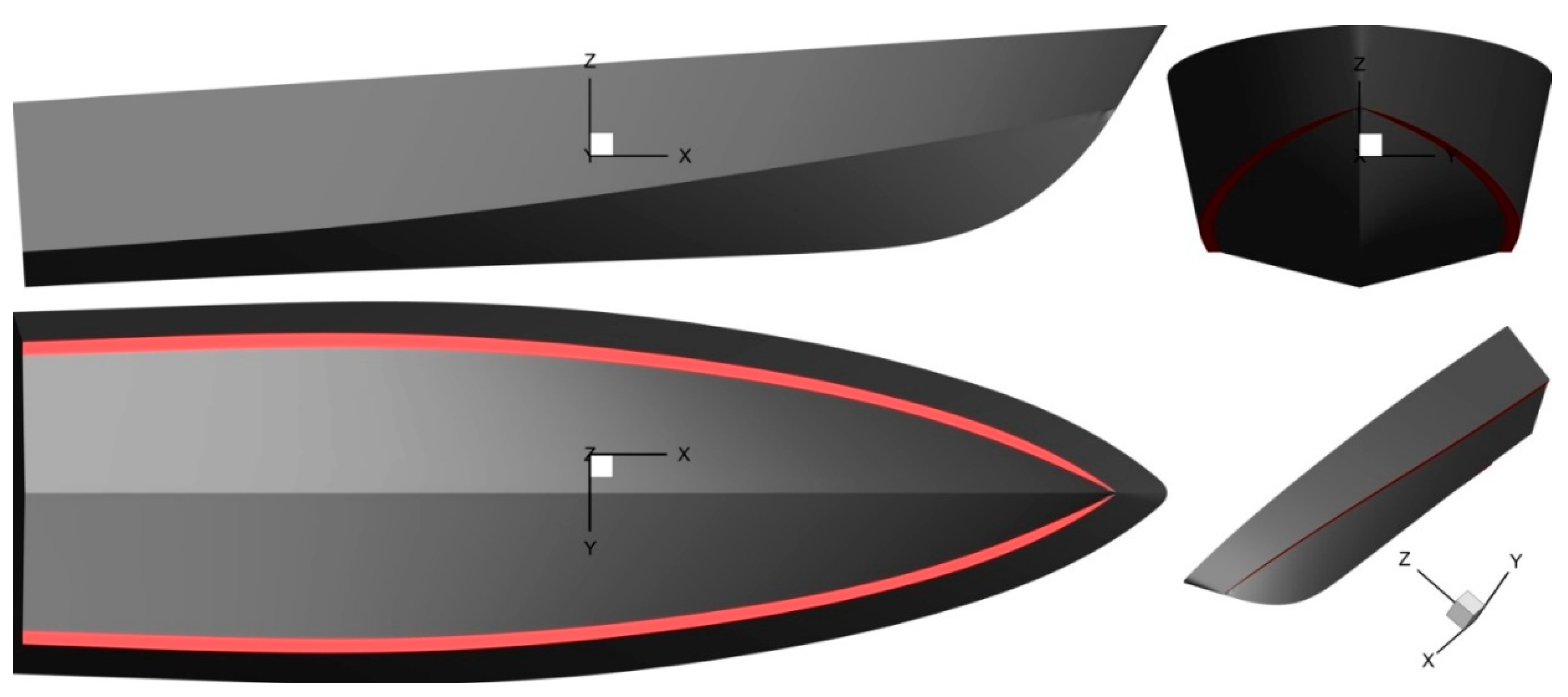
The study includes two main geometries; the first is used for a validation purpose wherein the EFD data are available [
13,
30], while the second is the main geometry wherein the comparative study takes place. The first geometry is depicted in
Figure 1, showing a simple boat geometry with an overall length of
LOA = 2.611 m, a mean dead rise of 14° and a bottom spray rail. The complete characteristics for this geometry are listed in
Table 1. The analysis conditions for this case correspond to a towing tank test performed and reported in [
30], wherein the ship was towed at various speeds, starting with 2 m/s and ending with 7.5 m/s, with a step 0.5 m/s. For this study, the target is to estimate the total resistance and the trim of the boat during the sailing condition.
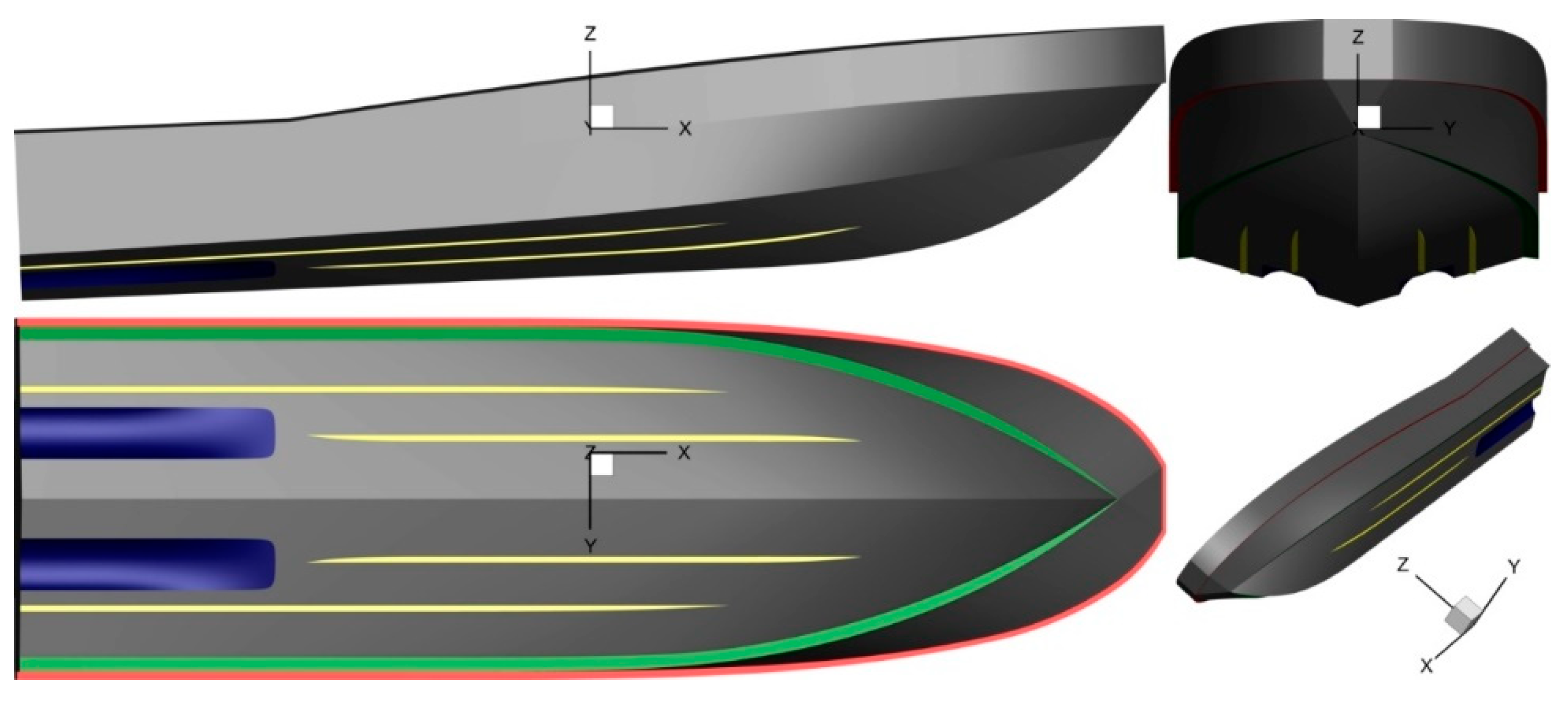
On the other hand, the second geometry, shown in
Figure 2, depicts the most complex geometry in the comparative analysis, denoted with the abbreviation V7. The basic geometry forms a simple boat configuration with a tunnel. In addition, additional whiskers are added to study their influence on the boat performance. The main characteristics of the boat with its seven altered features are listed in
Table 2, wherein every geometrical variation proposed is denoted with ‘Vn’ (i.e., V1 denotes the principal geometry, while the other variables include a modified tunnel geometry/dimensions or the addition of a whisker or two correspondingly).
The simulation condition indicates the boat sailing in an open sea with a speed range from 12 knots to 40 knots, with a speed step of 4 knots in every simulation, resulting in 8 speeds/geometry and a total 56 simulation cases. The foremost target in this study is to compare the main hydrodynamic characteristics (such as: drag, lift, trim, air entrapment, etc.) of the boat as a result of the geometrical change.
5. Conclusions
The CFD simulation of the hydrodynamic performance of a planing hull, taking into consideration several geometrical parameters modifications, such as the tunnel configuration, whiskers and spray rails, while studying their influence on the hydrodynamic parameters of the planing hull, was presented, taking into consideration two various stages. The first is to validate the capability of the CFD to accurately capture the basic hydrodynamic parameters of concern. This was achieved by performing a separate analysis for validating the numerically obtained results based on the EFD data provided in [
13]. This study also included a verification test to estimate the numerical errors and uncertainties, while also establishing a base for the proper choice of the grid cell size and time step. The second stage is to perform the comparative study for the hull under investigation, based on the information obtained from the first stage. This study also included a verification test for estimating the numerical uncertainties associated in the current study.
The verification and validation data for the first study were presented and were shown to have a proper agreement with the available experimental data in terms of resistance and trim angle. The verification study showed that the simulation was more dependent on the grid rather than the time step, wherein the influence of the time step changing was insignificant. Similarly for the comparative study, the verification test was concluded to be grid- and time-step-independent, a fact that reflects the proper choice of the grid cell size and time step for the simulation. However, the numerical parameters used for the simulation cannot be generalized from only a single study—further investigation is required. Still, as is well established in the CFD simulation, a proper combination between the time step and cell size can improve the quality of the numerical simulation and reduce the associated errors.
As for the comparative study, by quantitatively analyzing the variation in the global parameters, such as wetted surface, drag, lift, trim and sinkage, but also qualitatively investigation of the flow parameters, the following conclusions can be drawn:
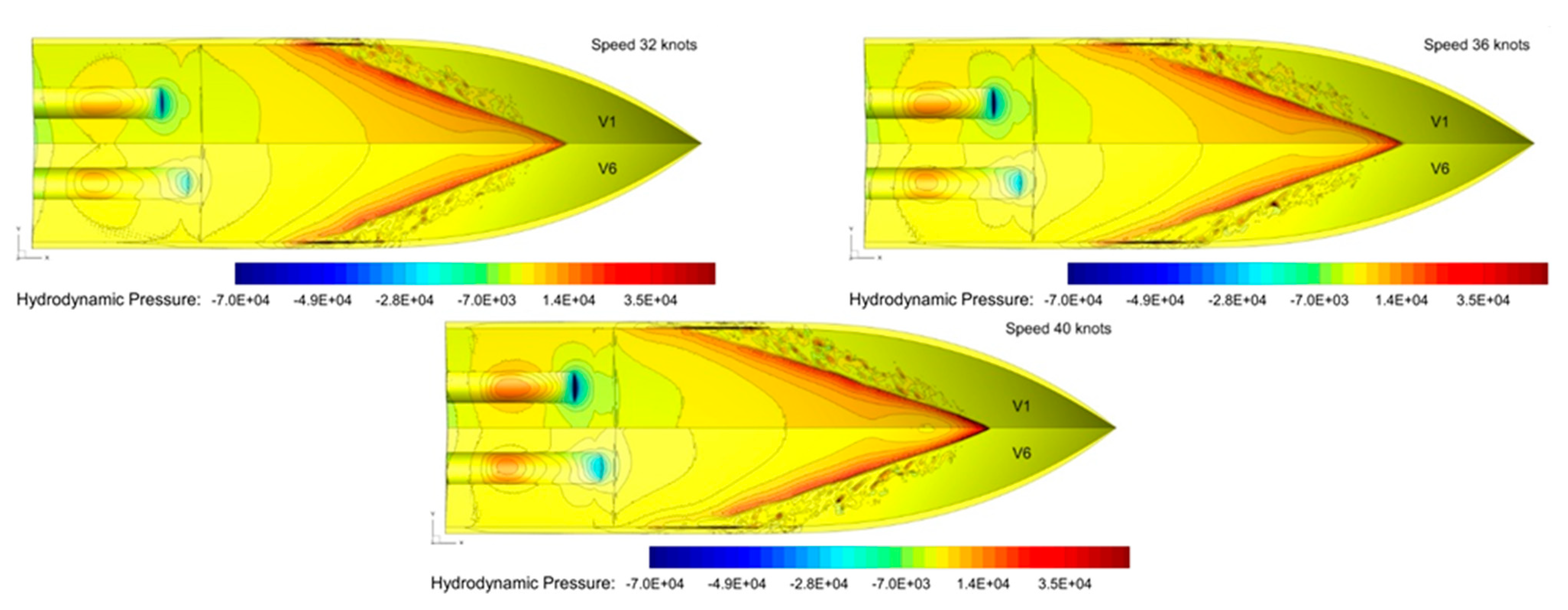
Tunnel shape improvement has brought no significant positive effect on global quantities, considering that most of the difference was less than 1% for all global quantities. Even so, the main reason for the tunnel shape improvement has been to reduce the spot of significant negative pressure on the front of the tunnel entrance, which is susceptible of flow detachment, which may lead to nonhomogeneous velocity fields in the propeller disc with direct effects on the propeller efficiency. The amelioration of the lower pressure area at the tunnel entrance can be checked in
Figure 7.
To investigate the effects of the spray rail width on the hull hydrodynamic performances, the width of the initial SR (0.11 m, V6) has been extended to 0.15 m (V4) and 0.19 (V3). In terms of ship resistance, the lower drag has been shown by the V4 for the range speed of 16 to 36 kn, but for the computed higher speed (40 kn), V6 experienced the minimum resistance. One important aspect for this particular case is the propeller shaft inclination of 13°. Moreover, the boat dynamic trim contributes to the increase in the shaft angle, which, by superposing effects, can reach very high inclinations with a negative influence on propeller efficiency. So, the decrease in the trim angle by 0.5° experienced by V4 should be seen as a benefit in terms of propulsion efficiency.
In order to study the effects of the whisker rails on the hull hydrodynamic performances, the boat has been equipped with one pair of whisker rails. Total resistance improvement of the hull with WR was by about 2% for the speed range of 20 to 40 kn.
To further investigate the effects of the WR on the hydrodynamic performances of the planing boat, two pairs of WR have been mounted on the bare hull of V4. Based on the findings from the study of one pair of WR, the shapes of the WR have been improved leading and trailing edge. In this case, mainly due to the friction reduction, a total resistance reduction of 2.5% to 9.7 % has been reached for the speed range of 32–40 kn.
Another approach to reduce the ship resistance of a planing boat is to modify the longitudinal position of the center of gravity. The change of the LOG by 0.2 m aft, led to a ship resistance reduction of 0.5–3.7% for the speed range of 24–40 kn. One important aspect that should be considered, in this particular case, is that the trim angle significantly increases at lower speeds (12–20 kn).
Based on the studies presented in the report and the design restriction, the hull version V7, which benefits from the performances of V4 and the improvement brought by the two pairs of whisker rails, can be considered the most effective from the hydrodynamic point of view due to a maximum drag reduction of 9.7% at 40 kn and of 5.9% at 36 kn. On top of that, the drag can still be reduced by moving the center of gravity toward the stern, but the price of increasing the trim should be played off.


