1. Introduction
If the biggest issue in the current shipbuilding and shipping industry could be expressed in one phrase, it would be “environmentally-friendly” [
1]. The International Maritime Organization (IMO), which deals with international issues in the field of shipbuilding and shipping, is strengthening various regulations to reduce emissions from ships. Starting from 1 January 2020, the change in the sulfur content regulation in ship fuel from 3.5% to 0.5% was the starting point [
2]. The paradigm of ship propulsion systems applying eco-friendly technologies is rapidly changing. For example an initial strategic goal of reducing greenhouse gas emissions from the international shipping sector by at least 50% by 2050 compared with 2008 was set at the 72nd MEPC(Marine Environmental Protection Committee) meeting [
3].
Ship fuels for achieving these emission reduction goals are expected to be ammonia, hydrogen, etc. [
4], but currently, technologies that can apply these fuels to ships are not commercially available. Therefore, to reach the goal by 2050, fuels such as LNG and LPG are emerging as alternatives as bridge fuels [
5,
6,
7,
8]. Since 2010, the use of LNG fuel has increasingly centered on LNG carriers with DF engines; since then, global engine manufacturers such as MAN-ES and WIN GD have developed ME-GI and X-DF engines [
9,
10,
11], and the use of LNG fuel has also increased in general vessels other than LNG carriers. LNG is the most researched alternative fuel for ships. A comparative analysis was made of the results of applying fuels such as natural gas, hydrogen, and methanol compared with the existing diesel fuel used for ships sailing off the coast of Croatia [
12], and another study was carried out on the environmental impact of applying LNG hybrid power systems to ships operating inland China [
13]. By formulating a ship’s energy efficiency and emission index, an LCA (Life Cycle Analysis) analysis was conducted on alternative fuels such as batteries, methanol, natural gas, hydrogen and ammonia applied in addition to diesel fuel, and the study aimed to identify the optimal combination [
14]. This study analyzed the effects of alternative fuels by approaching these studies via the as a LCA approach rather than applying the developed system.
However, despite its eco-friendliness, LNG has technical limitations in fuel storage tanks and fuel supply systems due to its extremely low temperature, as it is vaporized at −162 °C [
15]. In particular, various problems such as methane slip occur when LNG is used in an Otto cycle engine [
16]. Various studies are in progress, such as research on the application of high-pressure dual-fuel engines as a measure to reduce methane slip [
17] and how to change the responsive control mode by changing the timing of fuel injection and the shape of the spray nozzle etc. [
18]. However, it was confirmed that it is difficult to supply this fuel to ships due to the nature of the cryogenic fuel and since it has various limitations when applied to small and medium-sized ships caused by the small size of the ship itself, and it has been confirmed that the scalability of the its application to such ships is difficult [
19,
20].
LPG has similar components to LNG but, unlike LNG, it liquefies when pressurized at a constant pressure at room temperature without the need for low-temperature cooling to −162 °C. It is already widely used by industries. From an economic point of view, liquefied petroleum gas (LPG) has proven to be at least as attractive as LNG in terms of the shorter payback period [
6,
21], the lower investment costs, and less sensitivity to fuel price fluctuations [
22,
23]. In terms of bunkering, which is an important part of shipping applications, the fuel supply system is technically simple, so the construction costs are relatively low compared with those of LNG; in the case of a bunkering ship, the construction cost is expected to be one-third of compared to that for LNG. In addition, since most materials used in LPG storage tanks and fuel supply systems are suitable for ammonia storage, there is the advantage that it is possible to minimize the measures required for conversion to ammonia fuel storage tanks in the future [
24].
Matters related to newer types of fuel such as LPG are considered in the agenda of the IGF Code(International Code of Safety for Ships using Gases or other Low-flashpoint Fuels). The 8th session of the IMO CCC (Sub-committee on the Carriage of Cargoes and Containers) has agreed on the draft interim guidelines of for the safety of ships using LPG and the associated draft MSC(Maritime Safety Committee) circular. With this movement, it is expected that the application of LPG fuel to ships will gradually increase [
25].
There are cases of commercialization, such as large ships using the ME-LGIP engine developed by MAN-ES using LPG fuel [
22,
26]. According to data from the World LPG Association, a total of 71 LPG fueled vessels are expected to be operating by 2022. In the case of small and medium-sized ships, development of the technology and commercialization are in progress, focusing on the outboard motors of small boats in Europe and the United States, but the level of development of LPG engines that can be commercialized for small and medium-sized ships is still not high [
27]. The small and medium-sized ship market has a size comparable to that of the large ship market in terms of quantity, but it is facing great difficulties in the application of LPG in ships because there are no small LPG engines for propulsion or small LPG engines for power generation.
In this study, to understand the advantages of LPG as a marine propulsion fuel and to examine the fundamental problems and solutions of whether an LPG engine can be applied to small and medium-sized ships, we asked several questions. Is it possible to develop an LPG engine as a marine engine based on a conventional CNG engine? Is the LPG engine capable of continuous operation? Is it possible to develop an additional system for driving the LPG engine? Does the exhaust gas of the LPG engine satisfy the needs of the environment? To solve these fundamental questions, based on the conventional CNG engine for vehicles, we successfully developed an LPG engine for marine applications by identifying the characteristics of LPG fuel. The developed LPG engine was used in rolling and pitching situations reflecting the characteristics of marine environment. To verify the performance under continuous operation under a change in the load, it was used at 10%, 25%, 50%, 75%, and 100% and the performance was checked. In addition, a fuel gas supply system and LPG fuel injector were developed considering the characteristics of LPG, and the inside of the injector was modified and improved to overcome the problems occurring during LPG injection. Through this, we succeeded in developing a 200 kW LPG engine based on the generator output. In the case of fuel oil consumption related to the efficiency of the system, this was verified to be 49.5 kg/h, and a breakthrough performance was achieved in terms of the emissions as well.
Although interest in and demand for eco-friendly technology has increased, the technology is still far from the market. Through this study, it was possible to develop a marine LPG engine that has not previously been available in the market. In addition, it was possible to confirm the stability of its operation as a prime mover for power generation, and the auxiliary system, measurement system, and operational testing equipment of the engine developed through this study can be directly applied to engines to be developed in the future. Moreover, it can contribute greatly to the development of various models by resolving the market’s distrust about the dangers of LPG fuel and developing a safe testing procedure.
2. Methodology
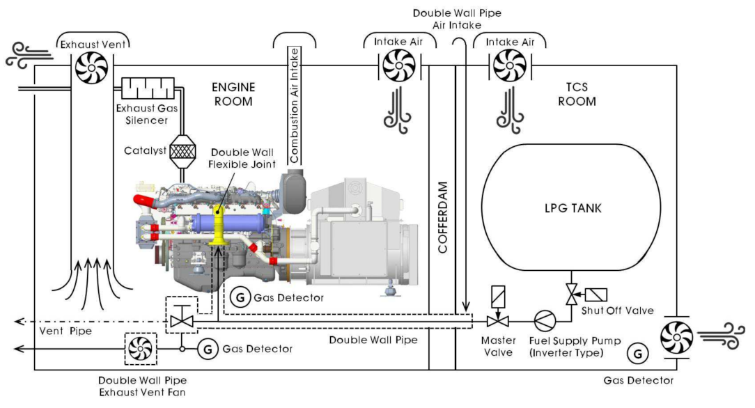
As shown in
Figure 1, to solve the fundamental questions about the LPG engine’s developability, continuous operability, and environmental characteristics, the various load characteristics of the ship should be considered.
2.1. Target Vessel
Therefore, among the eight types of representative coastal vessels in Korea, patrol vessels, which are vessels that perform duties for law enforcement and patrol, maintenance of safety and order in vessel traffic, and prevention of vessel hazards such as obstacles and harmful substances in harbors, were selected as the target vessels. These ships must have excellent maneuverability while navigating in smooth water areas, and must maintain appropriate stability and ensure a convenient on board environment. Of course, economical and stable operation is also required in the same way as merchant ships. The details of the vessel equipped with the developed LPG engine in this study is shown in
Table 1.
In addition, for propulsion, the ship has an electric propulsion system that applies two waterjet propulsion systems to reach the ship speed of 14 knots, and the LPG engine was designed to be used as a power source for the generator.
Second, the characteristics of LPG fuel were identified and the design of the combustion chamber, fuel consumption, and environmental characteristics were inferred on the basis of the combustion characteristics. LPG is a fuel mainly composed of hydrocarbons having 3 to 4 carbon atoms, and it is easily liquefied even at room temperature when pressurized to 10 to 20 bar or cooled to −49 °C or lower. At room temperature (15 °C), when propane is liquefied, its volume is reduced to 1/260 and butane is reduced to 1/230 in volume, making it easy to transport and store, and it has almost no polluting components such as sulfur. The specific gravity of propane is 0.51, which is about half the weight of water, and the density of the gas is 500~600 kg/m
3 at 15.6 °C. It has the advantages of high flammability, a high flame propagation speed for gas mixed with air, and a narrower explosion limit than city gas, but it is 1.5–2 times heavier than air [
1].
2.2. Analysis of LPG Fuel
Since the development of this LPG engine was based on a conventional CNG engine, the LPG engine was designed and manufactured through a comparative review based on the specifications of the CNG engine. The biggest difference between a CNG engine and an LPG engine is the knocking characteristics, which depend on the fuel, so the compression ratio should be different. In addition, CNG fuel is a compressed gas fuel and does not undergo phase change at room temperature. However, due to the nature of LPG fuel, the gas and liquid phases coexist at room temperature depending on the pressure conditions, so the configuration and control of the fuel supply system is a key technology. The LPG fuel used in the engine is designed to be used in a liquid state and to have above 96.77% propane, and the properties of the fuel used in this experiment are shown in
Table 2.
2.3. Design and Development of the LPG Engine
In an LPG engine with a liquid injection system, fuel is injected according to the stoichiometric air–fuel ratio according to the amount of intake air, and ignition is carried out by a spark plug through an ignition coil that generates a high voltage. When operating at a stoichiometric air–fuel ratio, it achieves relatively high output characteristics under the same emission conditions with compared to lean combustion, and is achieved through the oxidation and reduction reactions of noble metals applied to the three-way catalyst without the supply of a separate reducing agent by applying the three-way catalyst, which is a gas post-treatment device for exhaust gas. Its economic operation is possible because it can satisfy IMO Tier III emission regulations.
The propulsion system considered in this study was an electric propulsion system using a water jet pump, and two 180 kW permanent magnet synchronous motors were installed for the propulsion motor. For this research, a 200 kW LPG engine was selected and developed as shown in
Figure 2.
As shown in
Table 3, the developed LPG engine was designed as a 6-cylinder engine with an engine output of 230 kW and a torque of 138 kgfm compared with the conventional CNG engine. The Otto-cycle was used without modifications, the capacity to reduce NOx emission reductions was maintained, and the spark ignition method was applied.
The CNG engine used the MPGI (Multi Point Gas Injection) method, and the LPG engine used the MPLI (Multi Point Liquid Injection) method. A the maximum output of 230 kW was achieved, which is equivalent to that of the CNG engine at 1800 rpm, which is the number of revolutions of the generator.
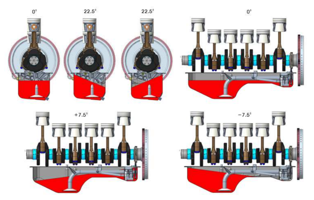
As shown in
Figure 3, the angle of inclination was designed on the basis of 15° static and 22.5° dynamic on the side slope, and 5° static and dynamic 7.5° dynamic on the end slope.
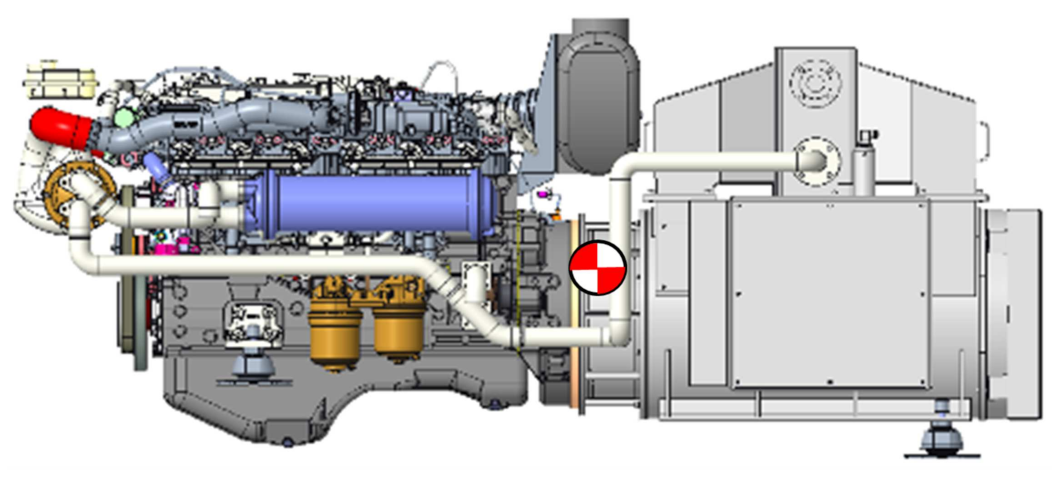
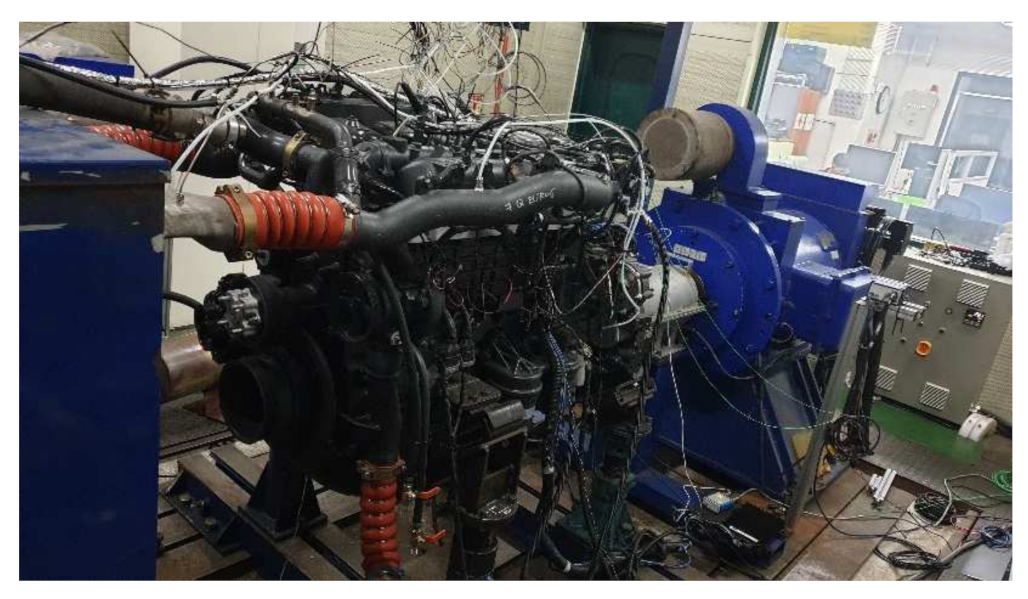
To test the performance of the manufactured engine, the dynamo shown in
Figure 4 and
Figure 5 was installed, and a load test bed was also designed and manufactured.
To satisfy the IMO Tier III emission regulations, the methods of reducing the emissions of an LPG engine include applying a three-way catalyst as a post-treatment device to stoichiometric operations, and a method of applying SCR (Selective Catalytic Reduction) as a post-treatment device for lean burning operations. When the engine is operating at a stoichiometric air–fuel ratio, it is possible to reduce the exhaust gas through the oxidation and reduction reactions of precious metals applied to the three-way catalyst without need for a separate reducing agent. When SCR is applied as a post-treatment device, it is necessary to continuously supply the SCR system device with the reducing agent (urea), so it is necessary to secure additional space for the reducing agent’s storage tank, thus creating additional failure factors such as the reducing agent supply pump and injection device. For stoichiometric operations, durability is required at a high exhaust gas temperature compared with lean combustion: in particular, resistance to exhaust valve and valve seat abrasion is important.
The base engine was developed as a stoichiometric engine to satisfy EURO 6, regulations, i.e., the European automobile emission regulations, and its components were developed according to heat load. The engine was run and its durability was verified. In particular, a water-cooled exhaust gas recirculation system (Cooled EGR) was applied to control the temperature of the exhaust gas, so this engine was optimized for stoichiometric operation.
In the three-way catalyst, an oxidation reaction converts HC and CO in the exhaust gas into and and a reduction reaction converts NO and into . In particular, precise control of the fuel is essential because the oxidation and reductions are repeated while crossing the range of excess and lean fuel close to the vicinity of the stoichiometric air–fuel ratio.
2.4. Combustion Chamber
Appropriate design of the combustion chamber is crucial in the design of an engine. Due to the nature of the spark ignition combustion method, it is important that a mixture is formed around the spark plug and the flame propagation distance of the combustion chamber achieves a uniform shape, so this must be reflected in the design stage.
Moreover, due to the characteristics of LPG fuel, the boundary of the phase change varies according to the composition ratio of propane and butane, the temperature and the pressure. Under the standard environmental conditions and the temperature of the engine room (45 °C), the fuel composition of propane forms a saturated vapor at a pressure of about 1.5 Mpa. This is required, and it is necessary to design and manufacture a fuel gas supply system that reflects this. The supplied fuel provides fuel to each cylinder of the engine through the injector module, and the liquid injector consists of one module, and it was necessary to equip it to be equipped with a sensor to monitor the fuel supply’s pressure and temperature.
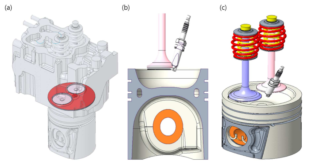
The shape of the piston’s combustion chamber was optimized to be close to a hemisphere, and the compression ratio was designed to be 9.5:1 to prevent knocking because of the nature of propane fuel. The piston’s shape and the combustion chamber were designed as shown
Table 4 and
Figure 6 in consideration of the piston’s rigidity according to the combustion pressure of the piston, the thermal load characteristics of the piston ring, and the oil consumption characteristics resulting from blow-by gas and oil blow-up.
2.5. Fuel Gas Supply System and Fuel Injector
As shown in
Figure 7, the fuel supply system was designed to maintain a pressure of 2 MPa through the fuel pump so that the liquid fuel supplied to the engine in a returnless form did not change into a gas phase.
The fuel supplied to the engine is injected in the liquid phase through the injector mounted on the intake manifold of each cylinder in
Figure 8 and supplied to each cylinder individually during the intake stroke.
The fuel supplied through the injector undergoes a compression stroke in the combustion chamber and is then ignited by the spark from the spark plug discharged through the ignition coil. The amount of fuel supplied to each cylinder through the injectors is controlled by the ECU (engine controller unit) according to the amount of air intake. When propane, which is a liquid fuel, is injected from the injector, the surrounding moisture is condensed by the heat of vaporization of the fuel, and the moisture condenses around the injector where the fuel is injected and then grows to prevent the fuel’s injection, causing icing. To prevent icing, as shown in
Figure 9, an icing tube made of a plastic tube was constructed from the injector’s firing port to the inside of the intake manifold so that vaporized fuel did not directly contact the injector. An icing tip that could support the icing tip around the icing tube was constructed.
The maximum operating pressure of the LPG liquid injection injector was 3 MPa, which ensured a safety factor of 50% compared with the actual fuel pressure of 2 MPa. Durability was verified by performing 1 billion operation tests under 1.5 MPa. The fuel supply method of the injector was a bottom feed method in which fuel is supplied from the lower side of the injector and injected to the lower side, and the fuel supply unit and the injector coil were separated vertically. The fuel injection hole inside the injector has a ball and seat structure that is advantageous for durability.
2.6. Cooling System
In the cooling system, the capacity of the intercooler was calculated based on the engine’s output and the fuel consumption based on the expected engine efficiency and the low calorific value of the fuel. It was necessary to calculate the cooling capacity to lower it to 40 °C. The seawater cooler must also calculate the exhaust gas heat from the exhaust gas flow rate and the temperature calculated from the fuel consumption and the volume of air. The seawater cooler capacity was calculated from the cooling capacity, excluding the engine’s output and the exhaust gas heat from the total energy supply. Finally, various sensors and measuring equipment were selected and a shop test was carried out.
As shown in
Figure 10, the seawater pump was driven by a gear linked to the crankshaft to supply the seawater necessary for the cooling systems, such as an intercooler, a seawater heat exchanger, and a water-cooled generator. The seawater pump was in the form of a flexible impeller, and it used the principle of creating a vacuum in the process of bending and unfolding wings made of rubber (Neoprene), sucking the fluid only with the pump, and moving it along the rotational direction to push it toward the discharge pipe. Because it has superior self-suction ability compared with a fixed impeller, it can be operated without damage to the impeller, so a separate transfer pump for filing seawater was not required, as in a fixed impeller pump, making it easy to deploy the pump.
The coolant pump was a centrifugal pump and was driven by a belt (V-ribbed type) by a damper pulley connected to the crankshaft. To prevent corrosion, it used antifreeze containing >40% ethylene glycol.
Figure 11 and
Table 5 show the details of the overall cooling system.
2.7. Test System and Equipment
To check and control the performance of the LPG engine, an FEV automation system consisting of an automation tower, DAQ (Data AcQuisition) in cell, and an automation program shown in
Figure 12 was installed in the control room, and an AC (Alternating Current) dynamometer controlled the load using an AC motor. The coolant temperature was measured, and a water-cooling controller that regulated it was connected to the engine and installed on site. An Emerson’s fuel flow meter and a Sierra’s air flow meter were installed to measure the amount of LPG fuel and air injected into the engine, and the combustion pressure sensor, combustion analyzer, and program from Kistler were used to check the combustion characteristics in the combustion chamber. Each component of the exhaust gas generated after combustion was analyzed with a Horiba’s exhaust gas analyzer. To ensure the reliability of each analytical device, they were calibrated every year at the Korea Testing Laboratory.
2.8. Control, Safety and Monitoring System
For data recording and analyzing the performance of the test engine, the control, safety and monitoring system shown in
Figure 13 and
Table 6 was used.
4. Discussion
In the case of this marine LPG engine, there was the problem of propulsion power loss when the engine stopped due to combustion failure. Therefore, it can only be used as a propulsion engine when an LPG engine can be developed as a dual fuel method. Alternatively, if the battery system performs a backup function when the engine is stopped by introducing a battery hybrid system, it can be used as a prime mover for propulsion, but there is the problem of reduced system efficiency caused by the double reduction gear system together with the battery-motor.
In addition, if the cost of developing this marine LPG engine and the production cost of commercializing it are not calculated, there is the problem of what benefit will be achieved by offsetting the CAPEX and OPEX if the system’s efficiency is calculated in terms of the cost.
In addition, if the market demand is not strong enough, it will be difficult to develop the engine in various capacities. It is expected that LPG engine technology will advance further through the support of government policies. Moreover, the change in the size of the vessel due to the additional space for the fuel tank caused by using CNG or LPG may cause another CAPEX problem and may lead to an additional OPEX problem.
The performance of the engine measured during this test can be confirmed by the load-SFOC (Specific Fuel Oil Consumption) curve shown in
Figure 22. Analysis was possible through the SFOC-load curve from an OPEX (OPerating EXpenditures) point of view. In terms of gas emission regulations, having no sulfur content is a characteristic of LPG fuel, and in the case of
, it satisfied the Tier III standards, confirming its use as an eco-friendly propulsion system. According to this, the total fuel consumption and total fuel cost are calculated by considering the operating characteristics of the vessel to which this LPG engine is applied, the fuel oil price, and the fuel consumption characteristics at a particular load. This is the basis for verifying whether benefits will occur after a certain period of time. However, in this study, it is difficult to calculate the pure CAPEX (CAPital EXpenditure related to mass production, so the process of calculating the payback has been omitted. In terms of GHG, according to the efficiency and the characteristics of its fuel, it may be one of the green solutions as a bridge fuel. However, according to the specific price scenario of LPG fuel its OPEX may have different outcomes.
Moreover, in the development of LPG engines as generators in electric propulsion systems, to find correlations and directions according to various environmental factors and aspects of engine control, and to improve the dynamic characteristics and efficiency, in terms of data analysis, the introduction of big data analysis is necessary for future research.
5. Conclusions
The government of the Republic of Korea is proposing various alternatives when promoting the conversion of eco-friendly public lines. However, there are many areas where technologically common and easily usable facilities have not been developed for marine use. Among these, the development of small and medium-sized propulsion systems is inadequate, and there is no marine LPG engine that can be applied as a power source for electric propulsion systems.
Accordingly, through this study, the characteristics of LPG fuel were identified based on a conventional CNG engine for shore use and a marine LPG engine was developed.
To this end, we succeeded in developing an 230 kW LPG engine for a waterjet-based electric propulsion system for patrol ships, which are small and medium-sized ships. We developed an engine that can be used in rolling and pitching situations reflecting the characteristics of marine applications. In order to verify the performance under continuous operation according to a change in the load, the operational performance was checked. We developed a fuel gas supply system and an LPG fuel injector considering the characteristics of LPG. To account for the icing problem that occurs when injecting LPG, an icing tube made of plastic was constructed from the injector’s continuous firing port to the inside of the intake manifold, which vaporized the liquid. The fuel did not come into direct contact with the injector, and an icing tip that could support the icing tip around the icing tube was constructed.
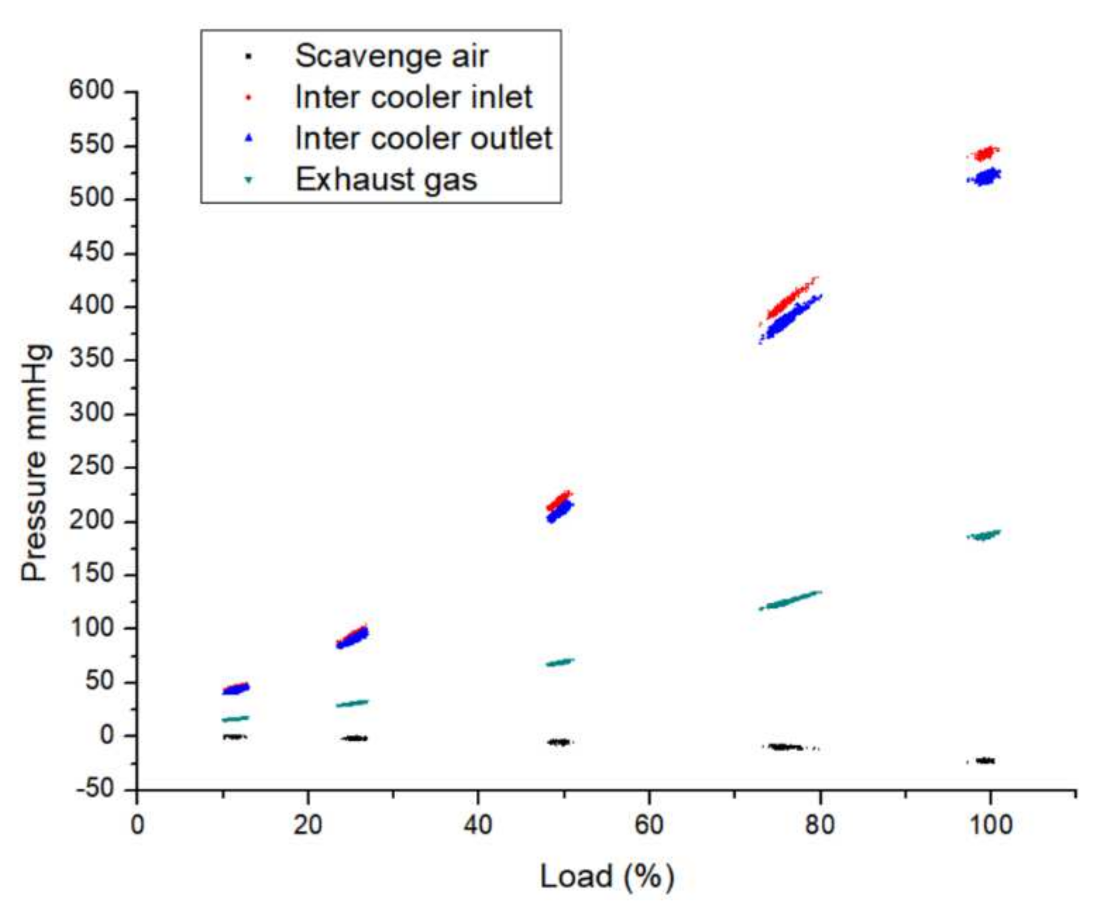
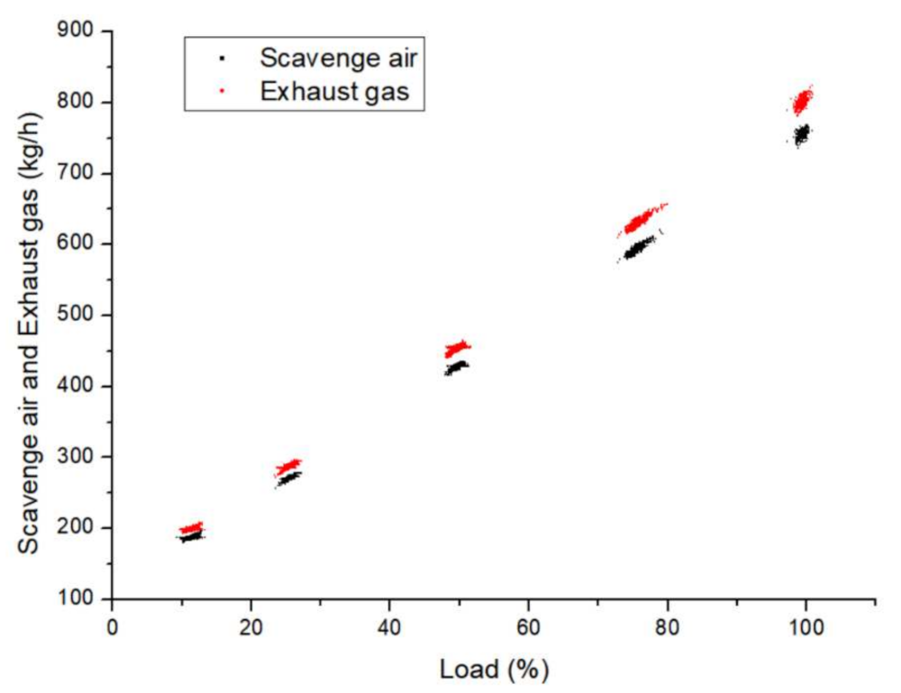
In addition, a cooling system for the entire engine was developed and the important control, safety, and monitoring systems required for test operation were developed. Depending on the load, the LPG fuel throttle varied from 22.8% to 49.8%, and the torque and engine output rose stably to show 202 kW and 1070 Nm, rpm at 1800 rpm. The average effective pressure was 13.4 bar at 100% output, and the maximum explosion pressure was 68.4 bar. As the amount of exhaust gas increased as the load increased, the pressure on the intercooler side increased, and the temperature of the exhaust gas also rose from 655 °C to 730 °C. In addition, the lubricating oil and coolant maintained a constant temperature and the temperature exhibited excellent stability. In terms of the exhaust gases of the developed LPG engine, its generation was 1 g/kWh, which satisfies the IMO Tier III requirements for an 1800 rpm prime mover, within 2 g/kWh. Although it showed a variable value under the same load, it was mainly within 6 g/kWh. In the case of carbon dioxide, it emitted 12.1% to 12.3% of the content.
Through this, we succeeded in developing a 200 kW LPG engine based on the generator’s output, and the amount of fuel related to the efficiency of the system was 49.5 kg/h.
In line with this, it will be possible to develop an LPG engine that can be applied to various propulsion systems through the development of medium-sized and large LPG engines.


