Article

Self-Powered and Robust Marine Exhaust Gas Flow Sensor Based on Bearing Type Triboelectric Nanogenerator

1
Dalian Key Laboratory of Marine Micro/Nano Energy and Self-Powered Systems, Marine Engineering College, Dalian Maritime University, Dalian 116026, China
2
Collaborative Innovation Research Institute of Autonomous Ship, Dalian Maritime University, Dalian 116026, China
*
Authors to whom correspondence should be addressed.
These authors contributed equally to this work.
J. Mar. Sci. Eng. 2022, 10(10), 1416; https://doi.org/10.3390/jmse10101416
Submission received: 4 August 2022 / Revised: 24 September 2022 / Accepted: 24 September 2022 / Published: 3 October 2022
(This article belongs to the Special Issue Advanced Marine Energy Harvesting Technologies)

Abstract

:
Exhaust gas flow takes a vital position in the assessment of ship exhaust emissions, and it is essential to develop a self-powered and robust exhaust gas flow sensor in such a harsh working environment. In this work, a bearing type triboelectric nanogenerator (B-TENG) for exhaust gas flow sensing is proposed. The rolling of the steel balls on PTFE film leads to an alternative current generated, which realizes self-powered gas flow sensing. The influence of ball materials and numbers is systematically studied, and the B-TENG with six steel balls is confirmed according to the test result. After design optimization, it is successfully applied to monitor the gas flow with the linear correlation coefficient higher than 0.998 and high output voltage from 25 to 106 V within the gas flow of 2.5–14 m/s. Further, the output voltage keeps stable at 70 V under particulate matter concentration of 50–120 mg/m3. And the output performance of the B-TENG after heating at 180 °C for 10 min is also surveyed. Moreover, the mean error of the gas flow velocity by the B-TENG and a commercial gas flow sensor is about 0.73%. The test result shows its robustness and promising perspective in exhaust gas flow sensing. Therefore, the present B-TENG has a great potential to apply for self-powered and robust exhaust gas flow monitoring towards Green Ship.

1. Introduction

Nowadays, along with the increase in maritime transport capacity, pollutant emissions from ships are occupying a large contribution in the impact to global air quality. Exhaust gas flow measuring plays a key role in ship exhaust emissions assessment and pollutants emission test, and the emission from ships needs to be verified according to International Maritime Organization (IMO) requirements [1,2,3]. Taking nitride oxides (NOx) as an example, the exhaust gas flow should be obtained first to calculate the NOx Emissions. The carbon balance method is the most common method. However, there are plenty of factors that should be taken into account, and the calculation process is highly complicated [4]. If the emission of ship exhaust gas can be measured directly, the calculation or measuring difficulty for emissions will be greatly reduced and contribute to the emission reduction towards Green Ship.
At present, gas flowmeters are generally in the form of ultrasonic [5], orifice plate and vortex meter [6], turbine [7], and pitot tube type [8]. Among them, the ultrasonic type is widely used in high humidity environments because of the ease of line cleaning and ability to measure moist air. The vortex type is mainly based on the vortex shedding frequency principle and is used in different systems because it is insensitive to the flow characteristics. Although the pitot tube type is high-temperature resistant, it should be necessary to prevent clogging by moisture or particles through a suitable design of the sensing tube. However, the exhaust gas temperature is high and contaminated by PM, so the robustness of the gas flow sensor should be highlighted. Even more, the existing flow sensor requires an external power supply, and the power supply in such a harsh environment will increase the cost of system design, maintenance, and application. Further, even if it is powered by battery, the life and safety of the battery in such a harsh environment will also lead to increased maintenance costs [9]. And there are unavoidable environmental pollution problems due to the aftertreatment of the battery as well. Therefore, it is of utmost importance to develop a self-powered and robust flow sensor for exhaust gas flow sensing on the ship.
Recently, triboelectric nanogenerator (TENG) provides a new way to solve the above problems. TENG was invented by Wang in 2012 [10], and is mainly based on the combination of contact electrification and electrostatic induction [11,12]. Alternating or direct current signals are generated during the energy conversion process by using TENG. The origin of alternating-[12] and direct-current [13,14] generation have been discussed in depth and impressive results have been achieved. These signals contain a large amount of dynamic information. Therefore, more and more researchers are conducting studies on self-powered sensing based on TENG in different fields, including wind speed [15,16,17], air flow [18,19], vibration [20,21], ocean wave [22,23], tactile [24,25], etc.
Within them, flow sensing has attracted many researchers’ interests and many excellent research results have been produced [26,27,28,29]. Phan et al. [26] proposed a gas flowmeter based on fluid-elastic flutter driven TENG, the gas flow rate was detected according to the regular contact between the PTFE membrane and the electrodes attached to the inner wall of the pipe. Su et al. [27] developed a self-powered flow rate sensor enabled by contact electrification (F-TENG), which demonstrated good current-velocity linearity in detecting the wind speed. Wang et al. [28] designed a flag-type TENG for wind speed and direction sensing, which has no obvious difference in the output performance with different relative humidity conditions. Zhu et al. [29] presented a windmill-like nanogenerator for wind speed measuring, and it is successfully applied to a wind speed of 1.7–4.8 m/s and 1.65–5.45 m/s detection according to the linear relation among the output current, signal frequency, and wind speed.
Most of the previous flow sensors have been applied to flow speed sensing in relatively clean and room temperature environments. Furthermore, some moisture or humidity tests have been carried out and preliminarily verified in humid circumstances [28]. However, for exhaust gas flow sensing, PM concentration and high temperature in the exhaust gas system are two key influential factors, which have not been taken into account. Besides, according to the characteristics of the exhaust gas flow monitoring, the relations between the required minimum gas flow velocity and the marine engine power should be emphasized. To address the above problems, a bearing type triboelectric nanogenerator (B-TENG) is proposed. The flow adaptability, structure optimization, and influence of PM contamination and high temperature on the exhaust gas flow sensing are systematically investigated in this work. The test result shows that it has great potential to realize self-powered and robust exhaust gas flow sensing on ships in such harsh environment.

2. Results and Discussion

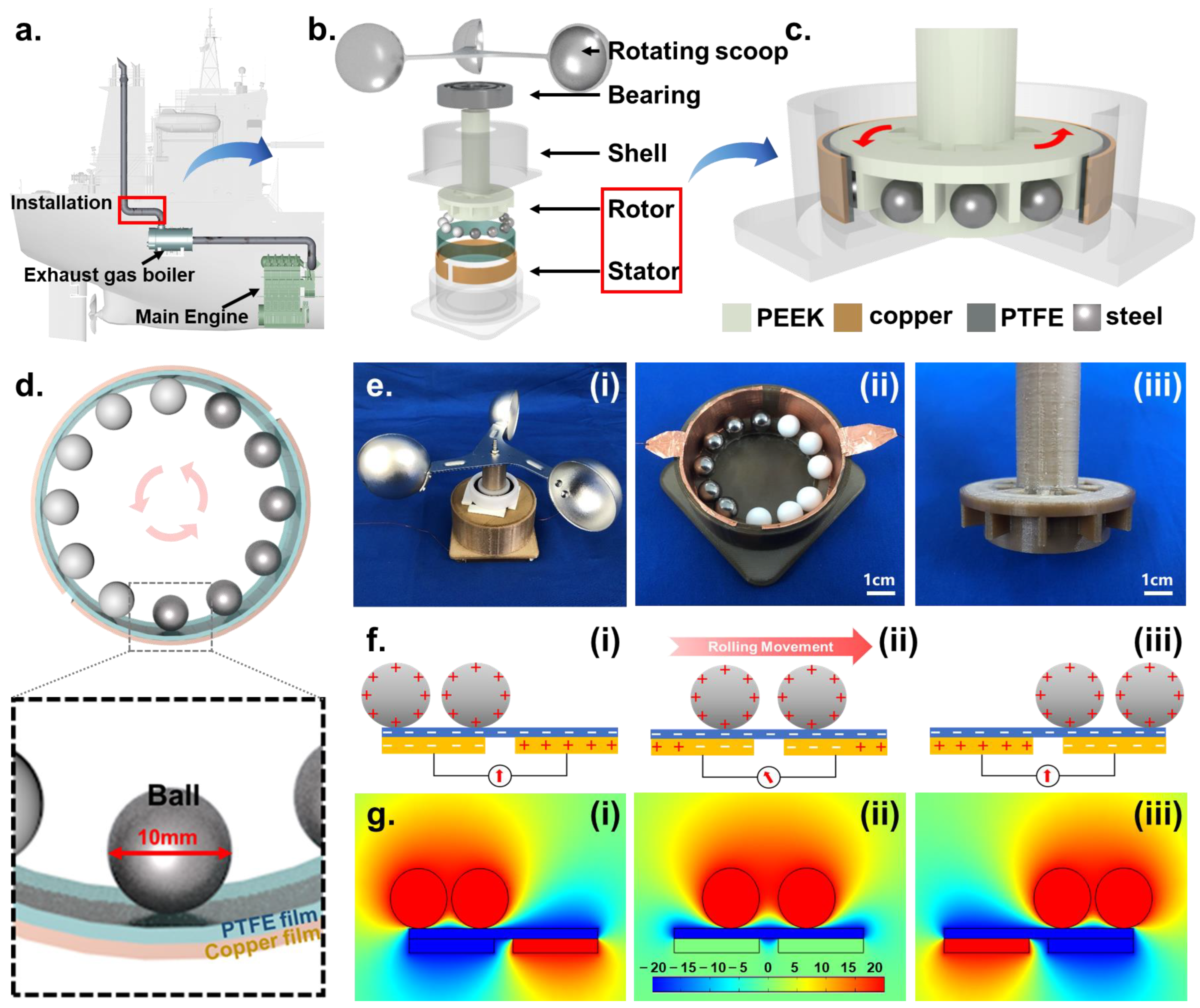
2.1. Structure and Working Principle of the B-TENG

Figure 1a shows the application scenario of the B-TENG in the exhaust gas system. On board ships, the exhaust gas flow from the main engine is not stable due to the influence of the turbocharger, which is used to improve the working efficiency of the main engine [30,31]. Additionally, the exhaust gas temperature is generally higher than 350 °C after the main engine, and higher than 250 °C even after the turbocharger. To reduce the influence of temperature, and take the stability of exhaust gas flow into account, the B-TENG is to be arranged after the exhaust gas boiler (EGB). In the EGB, the heat energy of the exhaust gas is transferred to the water to produce steam. So, the temperature of the exhaust gas is lower to about 180 °C after the EGB due to the heat release [32]. Moreover, as shown in Figure 1a, the cross-section of the EGB is much larger than the exhaust gas pipe, so the flow after the EGB will be more stable. Therefore, the arrangement of the B-TENG after the EGB can improve its working condition and measuring accuracy.
As depicted in Figure 1b, the B-TENG assembly consists of a rotating scoop, bearing, shell, rotor, and stator. The rotor and stator are made of polyether-ether-ketone (PEEK), which has good corrosion and high-temperature resistance. As illustrated in Figure 1c, the rotor is designed as the cactus stent to arrange the steel balls. Copper films are attached to the inside of the stator and PTFE film is attached to the copper film. Figure 1d demonstrates that two copper electrodes are designed symmetrically on the stator with specific intervals inside the B-TENG. There are 6 steel balls, which exactly cover one copper electrode in the circumferential direction. The steel balls and PTFE film are determined to be two friction materials according to the triboelectric series [33]. Besides, 6 PTFE balls are to fill the gaps and make the rolling of the B-TENG more stable. Figure 1e(i)–(iii) show the actual B-TENG assembly, stator, and rotor respectively. With the rotation of the rotating scoops, the steel balls are subjected to centrifugal force [34], as shown in Equation (1), due to being driven by the rotor.
F = m ω 2 r = m ( d θ d t ) 2 r
where m is the mass of the ball, ω is the angular velocity of the ball, r is the radius of gyration, and θ is the rotation angle. According to Equation (1), the centrifugal force will be larger with a higher rotation speed of the rotating scoop because of the gas flow, which will lead to a stronger triboelectric effect between the ball and the PTFE film.
Additionally, the structure of B-TENG is optimized to meet the lower limit of the exhaust gas flow measurement, which should be lower than gas flow speed under 25% of engine power. The start-up speed requirement of the B-TENG is depicted in “Start-up speed requirement of the B-TENG” in Description S1 in the supporting material. In Description S1, Table S1 shows the main working parameters of an actual marine main engine, and Equation S1 displays the estimated gas flow velocity according to the principle of mass conservation. As shown in Figures S1–S4, after optimization iteration, the lower start-up gas velocity of the B-TENG achieves 2.5 m/s, which meets the requirement of minimum gas speed working at 25% engine power.
In the final design of the B-TENG, the gas flow forces the scoop to rotate, and then leads to the rotation of the rotor. Driven by the rotor, the steel balls roll on the surface of the PTFE film. Several rotations lead to an adequate triboelectric effect between the steel balls and the PTFE film, then positive and negative charges will be generated on the surface of the steel balls and PTFE film. And then, as depicted in Figure 1f(i), when the steel balls only cover the length of one electrode, the potential among the steel balls, PTFE film, and two electrodes achieves equilibrium. As the rolling position of the steel balls changes, the potential difference between two copper electrodes also changes. It breaks the potential equilibrium and drives electrons to flow from the left electrode to the right one through the external circuit, which is illustrated in Figure 1f(ii). When all steel balls cover the other electrode exactly, a new potential equilibrium is achieved as shown in Figure 1f(iii). Then, with the rotation of the steel balls from the right electrode to the left one, a current opposite to that shown in Figure 1f(ii), is generated through the external circuit. The cycle starts over and repeats itself. Therefore, continuous rotation of the steel balls, driven by the gas flow, can produce continuous alternating current, which is also the key factor of sensing. The electric potential simulation is carried out by the COMSOL software to verify the working process of the B-TENG. As demonstrated in Figure 1g(i)–(iii), the simulation results are one-to-one correspondence to the working mechanism shown in Figure 1f(i)–(iii), which has proven the reasonability of the working principle.
The theoretical model of TENG originated from the modified displacement current of Maxwell’s equations. And then it can be simplified to be a capacitor model with time-varying capacitances, which is expressed as Equation (2) [12].
V = 1 C ( t ) × Q + V o c ( t )
Where V is the output voltage of the TENG, C(t) is the time-varying capacitance, Q is the transferred charges, and Voc(t) is the open-circuit voltage of the TENG. According to the above analysis, the detected exhaust gas flow rate (q) is related to the angular velocity (ω) and the voltage (V) of the B-TENG. According to the above balls’ centrifugal force [34] and the theoretical model of TENG [12], and since the angular velocity is related to the rotation frequency (fr) of the B-TENG, exhaust gas flow is therefore likely to be a function of voltage and/or frequency, as indicated in Equation (3).
q = φ ( V , f r )
Even more, the working mode of the B-TENG can be classified as the rolling mode freestanding TENG. And on basis of the freestanding TENG theory [35], the transferred charge is influenced by the triboelectric materials, and the contact area between the triboelectric layers. Therefore, the ball conditions including the ball materials and ball numbers in the B-TENG in this work are methodically studied.

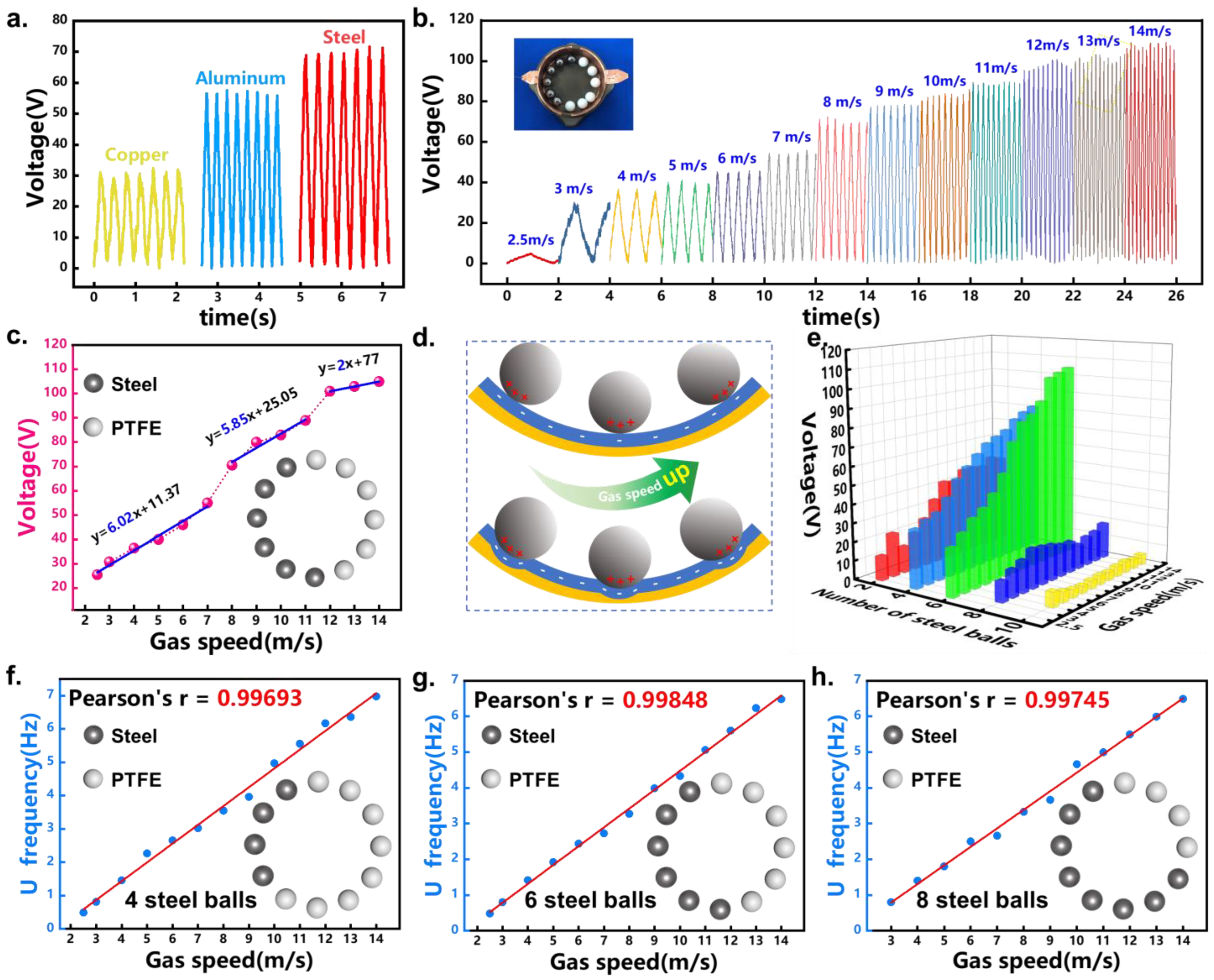
2.2. Effect of Ball Conditions on the Performance of B-TENG

To investigate the B-TENG output performance, a test system is set up as shown in Figure 2. As depicted in Figure 2a, the gas flow is generated by the blower, which is installed at the end of the test section. The test section is a wind tunnel, acting as a simulative gas pipe, in which the B-TENG is arranged to test the gas flow. The rotating speed of the blower can be adjusted by the speed controller to simulate different gas flow under different engine power. The output signal of the B-TENG is collected by the electrometer and then transferred to the LabView based computer through a data acquisition card. Figure 2b demonstrates the actual arrangement of the B-TENG in the wind tunnel. The B-TENG is mounted and fixed on a specially designed base to keep the rotating scoop in the center of the wind tunnel. The signal processing of the B-TENG is illustrated in Figure 2c, and the original signals can be converted to dominant frequency by a fast Fourier transform (FFT).
Considering different triboelectric series [33], for exploring the influence of different ball materials on the output performance of the B-TENG, the steel balls are replaced by copper or aluminum balls with the same size and quantity. As shown in Figure 3a and Figure S5, the result shows that the output voltage of the B-TENG with steel balls is higher than that with copper or aluminum balls under a gas speed of 8 m/s.
It is exhibited in Figure S5 that the output voltage of the B-TENG with copper balls increases with the increase of the gas speed from 3 to 5 m/s, and then decreases unstably after 6 m/s. The main reason for this trend may be that the charge transfer decreases due to the same material of the ball and electrode. Although the output voltage of the B-TENG with aluminum balls increases when the gas speed increases, the output performance of the B-TENG with steel balls is better than the other two in most cases. So, the B-TENG with steel ball is decided to be applied to continue further exploration.
Figure 3b demonstrates the output voltage of the B-TENG with steel balls at different gas speeds. The output voltage rises from 25 V at a gas flow speed of 2.5 m/s to about 106 V at 14 m/s. The reason for this trend is that with the gas flow speed increasing, the centrifugal force impact on the steel balls enlarges, which amplifies the contact area between the balls and the PTFE film. Then, it enhances the triboelectric effect inside the B-TENG, which increases the transferred charge, and then improves the output voltage of the B-TENG. However, as shown in Figure 3c, the voltage variation trend at low, medium, and high gas speeds is analyzed. In the range of 2.5–7 m/s, the fitted curve of the voltage is in accordance with y = 6.02x + 11.37. And the formulas of the fitted curves in the range of 8–11 m/s and 12–14 m/s are y = 5.85x + 25.05 and y = 2x + 77 respectively. It indicates that when the gas flow speed is high enough, the triboelectric effect enhancement between the balls and PTFE film will be retarded. The main reason is that the contact area between the ball and PTFE film enhances in the wake of larger centrifugal force under higher gas flow velocity, which is exhibited in Figure 3d. However, the deformation of PTFE film will reach maximum while the gas flow is high enough. Therefore, the rising tendency of the output voltage will slow down and reaches saturation [36].
Further, the B-TENGs with different numbers of 2, 4, 6, 8, and 10 steel balls are fabricated to analyze the output performance under different contact areas between steel balls and the PTFE film in the B-TENG. Referring to the working principle of the freestanding triboelectric-layer mode of the TENG [35], steel balls are arranged in adjacent positions. The blank spaces between the cactus stent and the stator are filled by PTFE balls. Figure 3e displays the output voltage of the B-TENG with two, four, and six steel ball numbers at different gas speeds. The B-TENG with two or four steel balls shows a similar trend to the B-TENG with six steel balls. However, the voltage of the B-TENG with two steel balls is about 50 V under a gas flow of 14 m/s, and it is about 80 V for the B-TENG with four balls. Both of them are lower than the voltage of the B-TENG with six balls, which is about 106 V under a gas flow of 14 m/s. The output voltages of the B-TENGs with 8 and 10 steel balls don’t exhibit the regular increasing tread with the increase of gas flow speed, and are much lower than that with six, four, and six steel balls. Especially for the B-TENG with 10 steel balls, the voltage of it is lower than 10 V under a gas flow of 3–14 m/s.
This is mainly because when the number of steel balls is more than six, the area covered by the steel balls is larger than that of a single electrode in the circumferential direction of the B-TENG. Therefore, the potential difference between two electrodes is lower, and then, it will weaken the charge transfer between two electrodes. According to that, if the number of steel balls is more than six, the more steel balls, the more obvious the weakening trend. The inset of Figure 3e describes the steel balls and PTFE balls arrangement in the B-TENG with six steel balls.
Moreover, it can be found that the frequency of the voltage signal enlarges along with the increase of the gas flow speed in addition to the output voltage growth in the wake of gas flow speed increasing as illustrated in Figure 3b. As a result, to further develop the B-TENG sensing properties, the output voltage of the B-TENG is processed by FFT. It follows that not only the voltage signal FFT results of the B-TENG with six steel balls, but also that of the B-TENG with 2, 4, 8, or 10 steel balls are in excellent linear correlation with the gas speed, which is illustrated in Figure 3f–h and Figures S6 and S7. After linear correlation analysis, all the Pearson’s correlation coefficients are larger than 0.99. Even the Pearson’s correlation coefficient between the FFT result of the B-TENG with 10 steel balls and gas speed reaches 0.99896 as shown in Figure S7. It is chiefly because the rotational speed of B-TENG mainly depends on the flow speed of the exhaust gas, and according to the working principle of B-TENG, all B-TENG will generate an AC electrical signal every rotation regardless of the number of steel balls. Therefore, the FFT results of the output signal for all B-TENGs can be applied to monitor the gas flow velocity. The result reveals the bright prospect of the B-TENG being a gas flow sensor. Meanwhile, the above analysis shows that the B-TENG with six steel balls has the highest output voltage and the best output performance, so considering the signal-to-noise ratio, the B-TENG with six steel balls is the optimal choice in this work.

2.3. Effect of Gas Property on the Performance of B-TENG

The exhaust gas of the ship’s main engine is mainly composed of combustion products after fuel oil combustion and excessive air, in which N2 and O2 account for most of the total exhaust gas because of the excessive air coefficient. The combustion products also include gaseous products such as CO2, CO, HC, and PM, in addition to NOx and SOX as mentioned above. Among them, the density of PM products in the exhaust gas is more than 100 mg/Nm3, which may affect the output performance of the B-TENG. In this regard, the effect of different PM concentrations on the output performance of the B-TENG is systematically tested. The test apparatus is illustrated in Figure 4a, including a transparent acrylic box, an adjustable-speed motor, and a duct fan. The B-TENG is arranged in the transparent acrylic box, and driven by the adjustable-speed motor. The duct fan and the acrylic box are connected by two bellows, so when the duct fan is working, the soot will be injected into the acrylic box and circulate in this system. The injection of the soot is shown in the yellow circle in Figure 4a. The dimension of the acrylic box is 300 × 250 × 250 mm (L × W × H), so its volume is about 1.875 × 10⁻² m3.
After the volume of the acrylic box is confirmed, different PM concentrations can be achieved by applying different weights of PM. Figure 4b shows the electronic balance used to weigh the PM. As demonstrated in Video S2, the B-TENG is driven by the adjustable-speed motor without PM in the acrylic box firstly. Then, PM is supplied into the acrylic box by the duct fan and circulated in the test system. As shown in Figure 4c and Video S2, just as the PM is injected into the box, the voltage signal drifts at the moment of adding PM, but its amplitude hardly changes. In addition, the output voltage under different PM concentrations is exhibited in Figure 4d. The voltage is stable at about 70 V no matter without or with different PMs of 0.94–2.25 mg (50–120 mg/m3). Moreover, the FFT results of voltage signals under different PM concentrations are almost the same and stable. This is mainly related to the structure of the B-TENG in this work. The lower part of the B-TENG is completely sealed, and in the upper part, the gap between the rotating scoop connecting rod and the shell is also sealed by the inner ring of the bearing. So that the contact between the power generation unit and the PM is isolated. It demonstrates the accuracy of the B-TENG for gas flow sensing under different PM concentration conditions.
As mentioned above, the temperature of the exhaust gas from the main engine is decreasing to about 180 °C after passing through the EGB. In order to test the output performance of the B-TENG under high temperature, the B-TENG is put into a heating box to be heated at about 180 °C for 10 min in this work, which is shown in Figure 4e and Video S3. After that, the steel balls are installed into the cactus stent again, and then the B-TENG is installed in the wind tunnel to carry out the sensing performance test further. The detected frequency under different gas speeds is exhibited in Figure 4f. It can be seen that the voltage frequency is lower than that before heating due to a little distortion after sudden cooling from 180°C to room temperature. Even though, an excellent linear correlation between the voltage frequency and the gas flow speed is still achieved. As shown in Figure 4f, the linear correlation coefficient is about 0.99707 with an error of less than 6%, which shows good high-temperature resistance and application prospect in exhaust gas sensing on ships. Even more, the frequency difference before and after heating would be studied systematically in the future. Therefore, after the above test, the presented B-TENG in this work has great potential to be applied in the contaminative and high-temperature exhaust gas flow in the future.

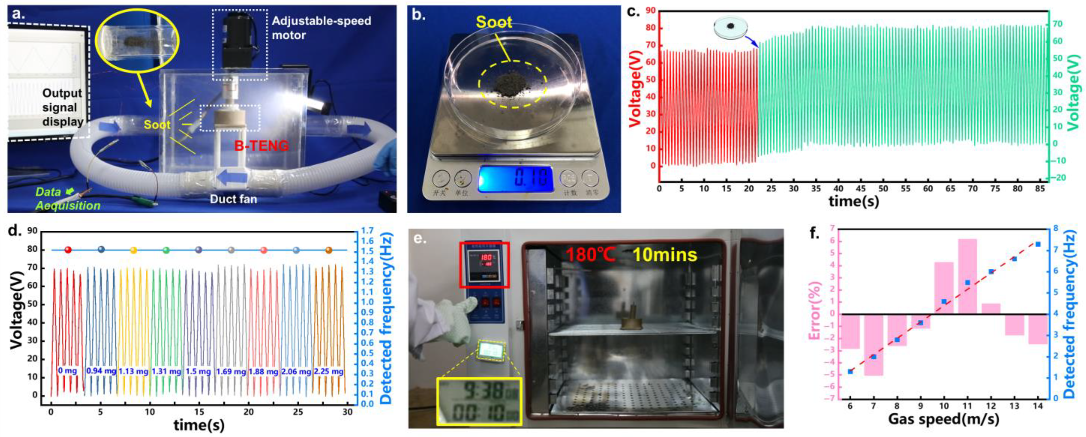
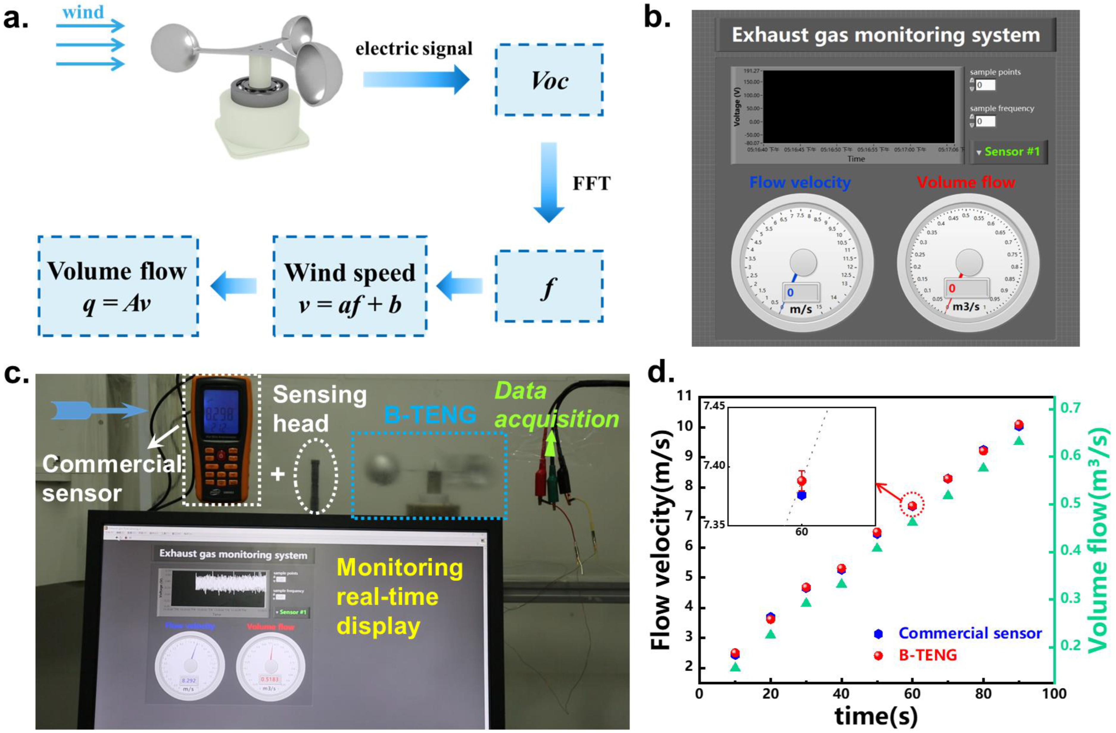
2.4. Demonstration of the B-TENG

To demonstrate the sensing performance of the B-TENG, a logic flowchart is designed and exhibited in Figure 5a. The output voltage signal is got by the electrometer, then it is processed by FFT.
According to the characteristics of the wind tunnel, the gas velocity is got by
v = a f + b
where a is a constant and f is the voltage signal frequency. The gas flow q could be obtained by
q = A v
where A is another constant. After data fitting, the gas velocity and flow are represented by v = 1.90426f + 1.46671 and q = 0.0625v, respectively.
Then, as illustrated in Figure 5b, a gas flow display interface based on LabView is developed. The display interface indicates the original output voltage signal, flow velocity, and volume flow according to the logic flow chart and Equations (4) and (5). Figure 5c and Video S4 depict the working process of the exhaust gas flow monitoring system. When the B-TENG is working, the gas velocity and volume flow are demonstrated in the display interface timely. Furthermore, the comparative gas flow speed is measured by a commercial hot wire anemograph by inserting the sensing head in the wind tunnel to verify the measuring accuracy of the B-TENG. As shown in Video S4, the B-TENG can monitor real-time flow velocity stably, and gas flow at 4.6, 7.4, and 10 m/s are successfully detected. As illustrated in Figure 5d, the detected velocity by the B-TENG and the commercial sensor is almost the same, and the mean error between them is about 0.73%, which shows its excellent sensing accuracy.

3. Conclusions

In conclusion, considering the actual environment in the exhaust gas system, a B-TENG is proposed as the exhaust gas flow sensor for the assessment of ship exhaust emissions. Due to the unique design, including applying a bearing and fabricated by PEEK, the B-TENG is sealed well and suitable for contaminative and high temperature exhaust gas flow sensing. The bearing on the shell also optimizes its minimum start-up speed, which meets the requirements of the gas flow sensing range in this work. The effects of the ball materials, ball numbers, PM concentration in the gas, and high temperature on the output performance of the B-TENG have been systematically studied.
The results show that the B-TENG with six steel balls are the optimum structure to be the self-powered flow sensor in this work. The output voltage under a gas speed of 2.5–14 m/s increases from 25 to 106 V due to the increase of the centrifugal force, which leads to a more efficient triboelectric effect between steel balls and PTFE film. Further, the voltage is processed by FFT, and the result indicates that the linear correlation of the voltage frequency with the gas flow speed is higher than 0.998. Moreover, PM concentration hardly has an influence on the output performance of the B-TENG driven by the motor, and the output voltage is stable at around 70 V with 50–120 mg/m3 PM. After being heated at 180 °C for 10 min, the linear correlation coefficient between the voltage FFT result and the gas flow speed reaches 0.99707, which proves its potential in applying in a high-temperature environment, even though voltage frequency is lower than that before heating. Finally, a display interface based on LabView according to the designed logic flowchart is applied to demonstrate the gas flow sensing performance of the B-TENG. The result compared with a commercial sensor exhibits its effectiveness in gas flow sensing. Therefore, the B-TENG proposed in this work can be applied for self-powered and robust exhaust gas flow monitoring on the ship. And it is helpful to obtain the pollutant emission not only in the bench test, but also during the whole operation cycle of the ship, which will provide a promising way for improving the pollutant emission control towards Green Ship.

4. Experiment Section

4.1. Fabrication of the B-TENG

The B-TENG is mainly composed of a rotor and a stator. The rotor including the rod and the cactus stent, the stator, the protecting shell, and the bedplate of the B-TENG were all printed by a 3D printer using the PEEK material. The rod of the rotor is designed to adapt to the standard bearing. The rotating scoop, steel balls, copper balls, aluminum balls, and PTFE balls were all standard products purchased from the market. Two copper electrodes with the same size were cut from a piece of copper foil with a thickness of 0.06 mm, and attached to the inner part of the stator. The PTFE film is made of PTFE tape with a thickness of 0.08 mm, and arranged on top of the copper electrode. Then different parts are installed together and fixed by glue to complete the final B-TENG.

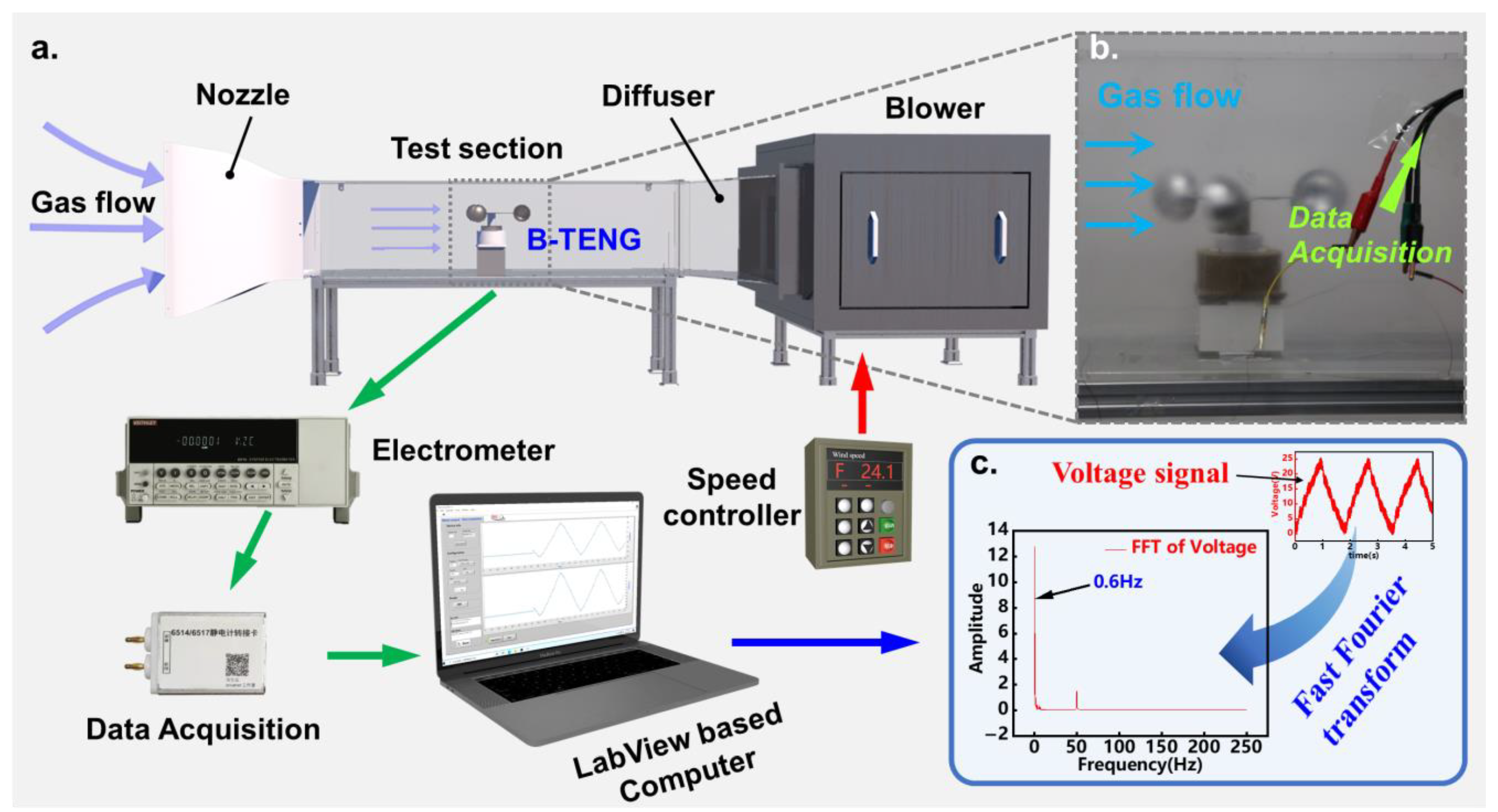
4.2. Measurement of the B-TENG Performance

In the sensing performance test, the B-TENG is arranged in the wind tunnel, which is made of transparent acrylic, with a dimension of 1000 × 250 × 250 mm (L × W × H). The gas speed in the wind tunnel is adjusted by the speed-adjustable blower, which is arranged at the end of the wind tunnel. In the PM concentration test, the B-TENG is arranged in a transparent acrylic box with the dimension of 300 × 250 × 250 mm (L × W × H). The PM is supplied into the box by a duct fan (LH-50-18W, Jiuyefeng, Shenzhen, China). The output signal was measured by an electrometer (Keithley 6514, Tektronix, Beaverton, OR, USA) and sent to the LabView-based computer through a DAQ device. The comparative gas flow speed is measured by a commercial hot wire anemograph (GM8903, BENETECH, Shenzhen, China). The FFT process was implemented by Origin software.

Supplementary Materials

The following supporting information can be downloaded at: https://www.mdpi.com/article/10.3390/jmse10101416/s1, Description S1: Start-up speed requirement of the B-TENG; Equation S1: exhaust gas flow velocity; Table S1: Main working parameters of an actual main engine on a ship; Figure S1: The start-up speed of the original B-TENG; Figure S2: The acting force analysis of the original B-TENG; Figure S3: The acting force analysis of the final B-TENG; Figure S4: The start-up speed of the final B-TENG; Figure S5: The output performance of the B-TENG with copper, aluminum and steel balls under different gas speed; Figure S6: The FFT results of the output voltage of the B-TENG with 2 steel balls under different gas speed; Figure S7: The FFT results of the output voltage of the B-TENG with 10 steel balls under different gas speed; Figure S8: The transferred charge under the PM concentration test; Video S1: Minimum start-up speed test of the B-TENG in Version 4.0; Video S2: Effects of PM on the output performance of the B-TENG; Video S3: Heating process of the B-TENG in the heating box at 180 °C for 10 min; Video S4: Demonstration of the B-TENG as the gas flow sensor.

Author Contributions

Conceptualization, T.D. and F.D.; methodology, T.D., F.D. and Y.Z.; software, F.D. and F.L.; validation, M.Z., Z.X. and F.L.; formal analysis, T.D. and F.D.; investigation, F.D., M.Z. and Z.X.; writing—original draft preparation, T.D. and F.D.; writing—review and editing, Y.Z., P.S. and M.X.; supervision, P.S. and M.X.; funding acquisition, T.D., P.S. and M.X. All authors have read and agreed to the published version of the manuscript.

Funding

This research was funded by the National Natural Science Foundation of China (Grant Nos. 52101345, 52101400), Scientific Research Fund of the Educational Department of Liaoning Province (Grant No. LJKZ0055), Fundamental Research Funds for the Central Universities (3132022211). The APC was funded by Dalian Maritime University.

Institutional Review Board Statement

Not applicable.

Informed Consent Statement

Not applicable.

Data Availability Statement

Data is available on request from the corresponding authors.

Conflicts of Interest

The authors declare no conflict of interest.

References

  1. Wan, Z.; Zhu, M.; Chen, S.; Sperling, D. Three steps to a green shipping industry. Nature 2016, 530, 275–277. [Google Scholar] [CrossRef] [Green Version]
  2. Ni, P.Y.; Wang, X.L.; Li, H. A review on regulations, current status, effects and reduction strategies of emissions for marine diesel engines. Fuel 2020, 279, 16. [Google Scholar] [CrossRef]
  3. Bijlsma, S.J. Minimal Time Route Computation for Ships with Pre-Specified Voyage Fuel Consumption. J. Navig. 2008, 61, 723–733. [Google Scholar] [CrossRef]
  4. China Classification Society. Guidelines for Testing and Survey of Emission of Nitrogen Oxides from Marine Diesel Engines; China Classification Society: Beijing, China, 2020. [Google Scholar]
  5. Fan, Z.C.; Jiang, W.T.; Wright, W.M.D. Non-contact ultrasonic gas flow metering using air-coupled leaky Lamb waves. Ultrasonics 2018, 89, 74–83. [Google Scholar] [CrossRef]
  6. Sun, H.J.; Yang, T.Y.; Ding, H.B.; Li, J.X.; Zhang, W.Q. Online Measurement of Gas and Liquid Flow Rates in Wet Gas Using Vortex Flowmeter Coupled With Conductance Ring Sensor. IEEE Trans. Instrum. Meas. 2022, 71, 14. [Google Scholar] [CrossRef]
  7. Dzemic, Z.; Sirok, B.; Bizjan, B. Turbine flowmeter response to transitional flow regimes. Flow Meas. Instrum. 2018, 59, 18–22. [Google Scholar] [CrossRef]
  8. Gonzalez, N.F.; Kindelan, J.C.; Martinez, J.M.L. Methodology for instantaneous average exhaust gas mass flow rate measurement. Flow Meas. Instrum. 2016, 49, 52–62. [Google Scholar] [CrossRef] [Green Version]
  9. Ma, S.; Jiang, M.D.; Tao, P.; Song, C.Y.; Wu, J.B.; Wang, J.; Deng, T.; Shang, W. Temperature effect and thermal impact in lithium-ion batteries: A review. Prog. Nat. Sci. 2018, 28, 653–666. [Google Scholar] [CrossRef]
  10. Fan, F.R.; Tian, Z.Q.; Wang, Z.L. Flexible triboelectric generator! Nano Energy 2012, 1, 328–334. [Google Scholar] [CrossRef]
  11. Niu, S.M.; Liu, Y.; Wang, S.H.; Lin, L.; Zhou, Y.S.; Hu, Y.F.; Wang, Z.L. Theory of Sliding-Mode Triboelectric Nanogenerators. Adv. Mater. 2013, 25, 6184–6193. [Google Scholar] [CrossRef] [PubMed]
  12. Chen, B.D.; Wang, Z.L. Toward a New Era of Sustainable Energy: Advanced Triboelectric Nanogenerator for Harvesting High Entropy Energy. Small 2022, 16, 2107034. [Google Scholar] [CrossRef] [PubMed]
  13. Song, Y.; Wang, N.; Wang, Y.; Zhang, R.; Olin, H.; Yang, Y. Direct Current Triboelectric Nanogenerators. Adv. Energy Mater. 2020, 10, 2002756. [Google Scholar] [CrossRef]
  14. Mariappan, V.K.; Krishnamoorthy, K.; Pazhamalai, P.; Manoharan, S.; Kim, S.-J. Decoupling Contact and Rotary Triboelectrification vs Materials Property: Toward Understanding the Origin of Direct-Current Generation in TENG. ACS Appl. Mater. Interfaces 2022, 14, 34593–34602. [Google Scholar] [CrossRef]
  15. Park, S.J.; Lee, S.; Seol, M.L.; Jeon, S.B.; Bae, H.; Kim, D.; Cho, G.H.; Choi, Y.K. Self-sustainable wind speed sensor system with omni-directional wind based triboelectric generator. Nano Energy 2019, 55, 115–122. [Google Scholar] [CrossRef]
  16. Ko, H.J.; Kwon, D.S.; Bae, K.; Kim, J. Self-suspended shell-based triboelectric nanogenerator for omnidirectional wind-energy harvesting. Nano Energy 2022, 96, 10. [Google Scholar] [CrossRef]
  17. Olsen, M.; Zhang, R.Y.; Ortegren, J.; Andersson, H.; Yang, Y.; Olin, H. Frequency and voltage response of a wind-driven fluttering triboelectric nanogenerator. Sci. Rep. 2019, 9, 6. [Google Scholar] [CrossRef] [Green Version]
  18. Wang, J.Q.; Liu, P.C.; Meng, C.L.; Kwok, H.S.; Zi, Y.L. Tribo-Induced Smart Reflector for Ultrasensitive Self-Powered Wireless Sensing of Air Flow. ACS Appl. Mater. Interfaces 2021, 13, 21450–21458. [Google Scholar] [CrossRef] [PubMed]
  19. Wang, Z.L.; Chen, J.; Lin, L. Progress in triboelectric nanogenerators as a new energy technology and self-powered sensors. Energy Environ. Sci. 2015, 8, 2250–2282. [Google Scholar] [CrossRef]
  20. Du, T.L.; Zuo, X.S.; Dong, F.Y.; Li, S.Q.; Mtui, A.E.; Zou, Y.J.; Zhang, P.; Zhao, J.H.; Zhang, Y.W.; Sun, P.T.; et al. A Self-Powered and Highly Accurate Vibration Sensor Based on Bouncing-Ball Triboelectric Nanogenerator for Intelligent Ship Machinery Monitoring. Micromachines 2021, 12, 218. [Google Scholar] [CrossRef] [PubMed]
  21. Prutvi, S.H.; Korrapati, M.; Gupta, D. Self-powering vibration sensor based on a cantilever system with a single-electrode mode triboelectric nanogenerator. Meas. Sci. Technol. 2022, 33, 13. [Google Scholar]
  22. Wang, X.Y.; Liu, J.H.; Wang, S.Y.; Zheng, J.X.; Guan, T.Z.; Liu, X.Y.; Wang, T.Y.; Chen, T.Y.; Wang, H.; Xie, G.M.; et al. A Self-powered Triboelectric Coral-Like Sensor Integrated Buoy for Irregular and Ultra-Low Frequency Ocean Wave Monitoring. Adv. Mater. Technol. 2022, 7, 10. [Google Scholar] [CrossRef]
  23. Lee, K.; Lee, J.W.; Kim, K.; Yoo, D.; Kim, D.S.; Hwang, W.; Song, I.; Sim, J.Y. A Spherical Hybrid Triboelectric Nanogenerator for Enhanced Water Wave Energy Harvesting. Micromachines 2018, 9, 598. [Google Scholar] [CrossRef] [PubMed] [Green Version]
  24. Xu, P.; Wang, X.Y.; Wang, S.Y.; Chen, T.Y.; Liu, J.H.; Zheng, J.X.; Li, W.X.; Xu, M.Y.; Tao, J.; Xie, G.M. A Triboelectric-Based Artificial Whisker for Reactive Obstacle Avoidance and Local Mapping. Research 2021, 2021, 10. [Google Scholar] [CrossRef]
  25. Jin, T.; Sun, Z.D.; Li, L.; Zhang, Q.; Zhu, M.L.; Zhang, Z.X.; Yuan, G.J.; Chen, T.; Tian, Y.Z.; Hou, X.Y.; et al. Triboelectric nanogenerator sensors for soft robotics aiming at digital twin applications. Nat. Commun. 2020, 11, 12. [Google Scholar] [CrossRef] [PubMed]
  26. Phan, T.K.; Wang, S.; Wang, Y.; Wang, H.; Xiao, X.; Pan, X.X.; Xu, M.Y.; Mi, J.C. A Self-Powered and Low Pressure Loss Gas Flowmeter Based on Fluid-Elastic Flutter Driven Triboelectric Nanogenerator. Sensors 2020, 20, 729. [Google Scholar] [CrossRef] [PubMed] [Green Version]
  27. Su, Y.J.; Xie, G.Z.; Xie, T.; Zhang, H.L.; Ye, Z.B.; Jing, Q.S.; Tai, H.L.; Du, X.S.; Jiang, Y.D. Wind energy harvesting and self-powered flow rate sensor enabled by contact electrification. J. Phys. D Appl. Phys. 2016, 49, 8. [Google Scholar] [CrossRef]
  28. Wang, Y.; Yang, E.; Chen, T.Y.; Wang, J.Y.; Hu, Z.Y.; Mi, J.C.; Pan, X.X.; Xu, M.Y. A novel humidity resisting and wind direction adapting flag-type triboelectric nanogenerator for wind energy harvesting and speed sensing. Nano Energy 2020, 78, 9. [Google Scholar] [CrossRef]
  29. Zhu, X.Y.; Cao, X.; Wang, Z.L. Windmill-Like Nanogenerator for Harvesting Low-Speed Wind Energy and Wind Speed Measuring. Adv. Mater. Technol. 2022; in press. [Google Scholar] [CrossRef]
  30. Pistek, V.; Kucera, P.; Fomin, O.; Lovska, A. Effective Mistuning Identification Method of Integrated Bladed Discs of Marine Engine Turbochargers. J. Mar. Sci. Eng. 2020, 8, 379. [Google Scholar] [CrossRef]
  31. Figari, M.; Theotokatos, G.; Coraddu, A.; Stoumpos, S.; Mondella, T. Parametric investigation and optimal selection of the hybrid turbocharger system for a large marine four-stroke dual-fuel engine. Appl. Therm. Eng. 2022, 208, 17. [Google Scholar] [CrossRef]
  32. Tien, W.K.; Yeh, R.H.; Hong, J.M. Theoretical analysis of cogeneration system for ships. Energy Conv. Manag. 2007, 48, 1965–1974. [Google Scholar] [CrossRef]
  33. Zou, H.Y.; Zhang, Y.; Guo, L.T.; Wang, P.H.; He, X.; Dai, G.Z.; Zheng, H.W.; Chen, C.Y.; Wang, A.C.; Xu, C.; et al. Quantifying the triboelectric series. Nat. Commun. 2019, 10, 9. [Google Scholar] [CrossRef] [PubMed] [Green Version]
  34. Chen, J.; Guo, H.Y.; Hu, C.G.; Wang, Z.L. Robust Triboelectric Nanogenerator Achieved by Centrifugal Force Induced Automatic Working Mode Transition. Adv. Energy Mater. 2020, 10, 8. [Google Scholar] [CrossRef]
  35. Niu, S.M.; Liu, Y.; Chen, X.Y.; Wang, S.H.; Zhou, Y.S.; Lin, L.; Xie, Y.N.; Wang, Z.L. Theory of freestanding triboelectric-layer-based nanogenerators. Nano Energy 2015, 12, 760–774. [Google Scholar] [CrossRef] [Green Version]
  36. Fang, Y.; Tang, T.Y.; Li, Y.F.; Hou, C.; Wen, F.; Yang, Z.; Chen, T.; Sun, L.N.; Liu, H.C.; Lee, C.K. A high-performance triboelectric-electromagnetic hybrid wind energy harvester based on rotational tapered rollers aiming at outdoor IoT applications. iScience 2021, 24, 24. [Google Scholar] [CrossRef] [PubMed]
Figure 1. Application scenario, structure, and working principle of the B-TENG. (a) Schematic installation of the B-TENG in the exhaust gas system on ship; (b) composition of the B-TENG; (c) detailed structure of the rotor and stator; (d) arrangement of the balls, PTFE film and copper electrodes; (e) actual image of the (i) B-TENG assembly, (ii) stator and (iii) rotor; (f) (iiii) working principle of the B-TENG; (g) (iiii) electric potential distribution simulation results of the B-TENG by COMSOL Multiphysics.
Jmse 10 01416 g001
Figure 2. Output performance test system for the B-TENG. (a) test apparatus arrangement; (b) image of the B-TENG installed in the test section; (c) fast Fourier transform of the voltage signal.
Jmse 10 01416 g002
Figure 3. Output performance of the B-TENG. (a) output performance of the B-TENG with copper, aluminum and steel balls under gas speed of 8 m/s; (b) output voltage of the B-TENG under different gas speed. (c) the rising tendency of the output voltage under different gas speed; (d) contact status between steel ball and PTFE film (e) output voltage trend of the B-TENG with different number of steel balls under different gas flow; the FFT result of the output voltage signal of the B-TENG with (f) 4, (g) 6, and (h) 8 steel balls under different gas speeds.
Jmse 10 01416 g003
Figure 4. Output performance of the B-TENG under different PM concentration and after heating to 180 °C for 10 min. (a) Different PM concentration test system; (b) electric balance for weighing PM; (c) output voltage of the B-TENG before and after contaminated by PM; (d) output voltage and the FFT results of the voltage under different PM concentration; (e) heating process of the B-TENG in the heating box; (f) output performance of the B-TENG after high temperature heating under different gas speed.
Jmse 10 01416 g004
Figure 5. Demonstration of the B-TENG as gas flow sensor. (a) The logic flowchart for gas flow sensing by the B-TENG; (b) Display interface based on LabView; (c) Test system for the demonstration of the B-TENG as gas flow sensor; (d) Gas flow sensing comparison between the commercial sensor and B-TENG.
Jmse 10 01416 g005
Publisher’s Note: MDPI stays neutral with regard to jurisdictional claims in published maps and institutional affiliations.

