Article

Mechanism of Mechanical Analysis on Torsional Buckling of U-Shaped Bellows in FLNG Cryogenic Hoses

1
Department of Engineering Mechanics, State Key Laboratory of Structural Analysis for Industrial Equipment, Dalian University of Technology, Dalian 116024, China
2
Ningbo Research Institute, Dalian University of Technology, Ningbo 315016, China
3
College of Mechanical and Electrical Engineering, Harbin Engineering University, No. 145 Nantong Street, Harbin 150001, China
*
Author to whom correspondence should be addressed.
J. Mar. Sci. Eng. 2022, 10(10), 1405; https://doi.org/10.3390/jmse10101405
Submission received: 25 August 2022 / Revised: 16 September 2022 / Accepted: 20 September 2022 / Published: 1 October 2022

Abstract

:
Floating liquefied natural gas (FLNG) cryogenic hoses can be employed for the transmission of liquefied natural gas (LNG). Usually, U-shaped metal bellows can be applied as the inner lining of FLNG cryogenic hoses. In installation, positioning and other working conditions, torsion is one of the main loads, and torsional buckling instability is a major failure mode of U-shaped metal bellows of FLNG cryogenic hoses. In the current research, the buckling instability of bellows under torsional loads has been investigated in detail, the mechanical mechanism of deformation in torsional buckling mode of bellows has been analyzed and the influence of the structural design parameters on the stability performance has been summarized. It was seen that the axis of the bellows was presented as a spiral line shape during the torsional buckling stage. At the same time, the torsional buckling properties of toroid and spiral bellows were analyzed. The obtained results showed that the torsional buckling stability of the spiral bellows was weaker than that of the toroid bellows and increase of the spiral angle of the spiral bellows intensified this trend. In addition, the post-buckling analysis of U-shaped bellows under torsional loads was carried out by means of experiments and finite element simulation. It was shown that the results obtained from finite element (FE) analysis in this research presented a relatively accurate critical torque value and a consistent buckling instability mode, compared with the experimental results. On this basis, the effects of common defects such as thickness thinning on the torsional stability of bellows were investigated. Considering the geometric defect of thickness thinning, the error of FE analysis was reduced further, and it was found that the defect could significantly decrease the stability of the bellows. The above analysis results could provide a reference for structural design and post-buckling analysis of bellows.

1. Introduction

Bellows are regular corrugated tubes with excellent bending characteristics and are extensively applied as expansion joints in pipeline systems [1]. In recent years, bellows have been applied as lining layers of cryogenic hoses in floating liquefied natural gas (FLNG) systems, which are floating liquefied natural gas (LNG) storage devices and new offshore floating LNG production systems. FLNG cryogenic hoses can also be employed for the transmission of LNG and are a key component of FLNG systems. As the inner lining of FLNG cryogenic hoses, metal bellows make direct contact with cryogenic transmission media, as shown in Figure 1. Thus far, several safety accidents of bellows have been reported [2,3,4]. Therefore, evaluation of the safety performance of bellows is of great significance.
In installation, positioning and other working conditions, torsion is one of the main loads, and torsional buckling instability is among the dominant failure modes of U-shaped metal bellows of FLNG cryogenic hoses [5]. Thus far, the number of research works conducted on bellow torsion is much lower than that on tension and bending. The torsional load of bellows was ignored in previous studies because of the unique torsional behaviors of bellows. Watanabe [6] applied a gradient element and general thin shell theory to analyze the elastic stress and torsional buckling of U-shaped bellows for the first time. Similarly, Broman [7] simulated the dynamic properties of flexible metal bellows with beam elements. Compared with the shell element model, the size of the beam element model was decreased by 100 to 1000 times. Radhakrishna [8] investigated the effects of elastically restrained ends on axial natural frequencies considering finite stiffness axial restraints on bellows to solve the set of equations with non-homogeneous boundary conditions. Kondapalli [9] analyzed different types of stresses of U-shaped bellows under internal pressure based on the EJMA method and finite element simulation separately, and compared the results of the two methods.
In terms of experimental research on torsion and stability of bellows, Rieger [10] performed several experiments on bellows with various diameters and found that the ultimate torque of the bellows was related to stability, not deformation or load cycle number. Lu [11] performed experimental studies on bellows’ torsional buckling. Dennis [12] studied column instability and plane instability of U-shaped bellows under internal pressure. In his study, a solution to avoid column instability was presented and practical suggestions for the structural design of bellows were given. Yang [13] developed an equivalent analysis model of bellows and analyzed the torsional performance based on an asymptotic homogenization method, which could save much time with little error compared with the traditional simulation method. In addition, many experimental studies have also been carried out on the buckling instability of other thin-walled structures. Wang [14,15] investigated the buckling instability of stiffened shells in launch vehicles. Imperfection sensitivity of stiffened shells under axial compression was also explored. Knockdown factors were predicted based on FE model and verified with experimental test results. Jiao [16,17] studied the buckling behaviors of thin-walled cylindrical shell structures under axial compression by experimental and numerical methods. By comparison with the experimental results, the feasibility and accuracy of the developed finite element (FE) model were validated. This indicated that localized axial compression load played a key role in the buckling behaviors of thin-walled cylindrical shells. Mohammad [18,19] carried out lateral torsional buckling studies on a bidirectional exponentially functionally graded monosymmetric C-shaped beam and a monosymmetric tapered I-beam with the cross-section varying longitudinally separately based on the Euler–Bernoulli beam theory, and the accuracy of the theoretical research was verified by numerical simulation.
In the current research, firstly, FE models for two types of U-shaped metal bellows, i.e., toroid and spiral bellows, were established. A linear torsional instability analysis of the two types of U-shaped metal bellows was conducted. The influences of different structural parameters on the critical buckling torque of bellows were analyzed, and the properties of toroid and spiral bellows were compared. The structural sensitivity behaviors of torsion buckling were summarized in Section 2, as a basis for post-buckling analysis. Secondly, buckling analysis was extended to a post-buckling stage in Section 3. The torsional buckling experiment on toroid bellows was carried out. In addition, the post-buckling process of the bellows was analyzed in an FE model by introducing linear buckling results to post-buckling analysis as the initial deformation. The critical torque value of post-buckling analysis in the FE model obtained in the current research was compared with the experimental results, and the error was only about 3.3%. Thirdly, the causes of errors were analyzed based on geometric structural defect of bellows and the effects of wall thickness defects on the post-buckling of bellows under torsional loads were explored. After considering and correcting the defects of FE model, the errors of the result obtained in this work were controlled to only about 0.9%.

2. Linear Buckling Analysis of Bellows under Torque
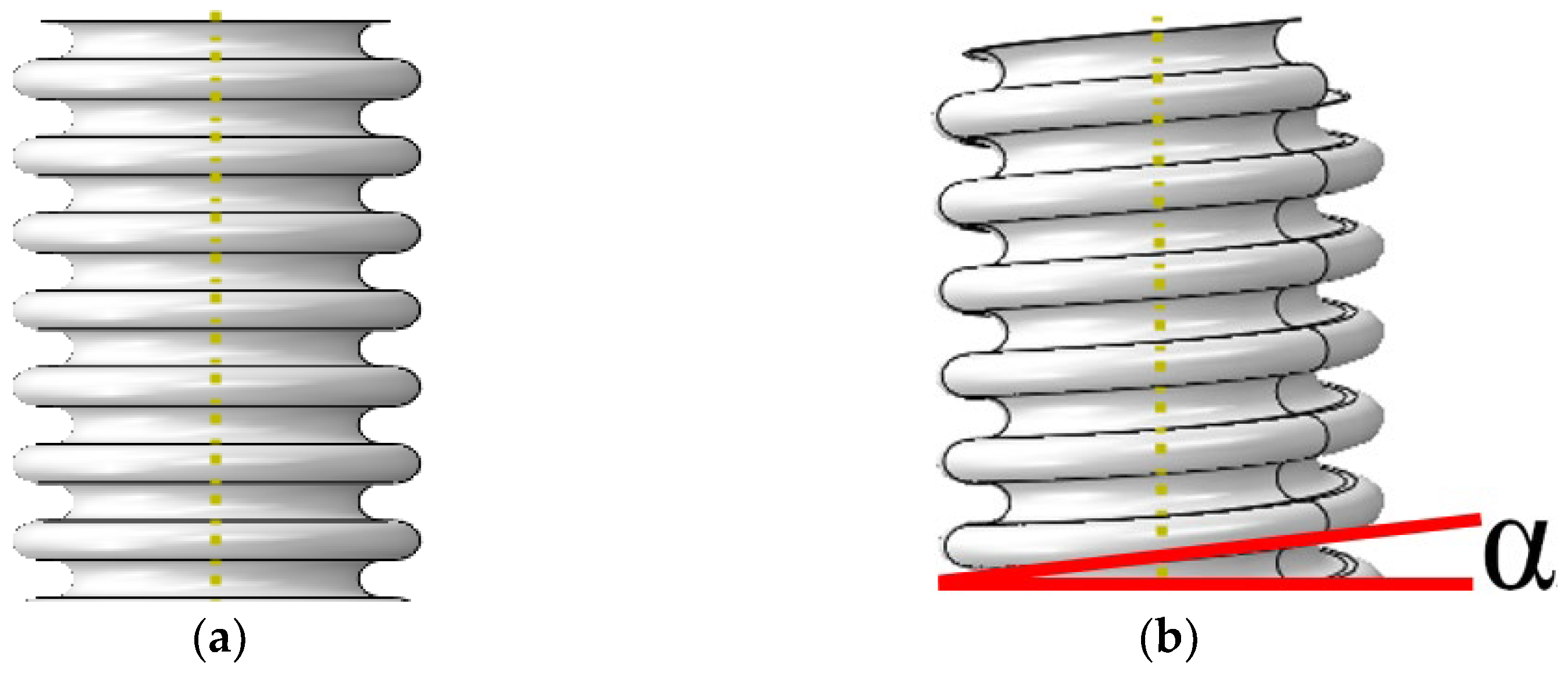
2.1. Bellow Models

As the lining layer of FLNG cryogenic hoses, two types of U-shaped metal bellows are commonly applied in practical engineering, as shown in Figure 2, including toroid (Figure 2a) and spiral (Figure 2b) bellows. In the figures, α is the spiral angle of the spiral bellows.
The structure of U-shaped bellows can be described by convolution number n , convolution pitch q , wall thickness d , convolution depth h , outer radius R 1 , inner radius R 0 and average radius R m , as presented in Figure 3. These factors can have relatively significant influences on the torsional buckling performance of bellows [20]. In order to investigate the linear buckling of bellows, buckling modes and critical torque values were evaluated under different design parameters, based on a standard bellows model. The structure and material parameters of the standard model in Section 2 were as described in Table 1, and the material of the bellows was tin bronze.
The buckling behavior studied in this research was a typical mechanical problem of nonlinearity and large deformation, which the ABAQUS software has a strong ability to deal with. Therefore, the FE models in this research were established and analyzed based on the ABAQUS software [15,21]. As could be seen from the structural parameter values, the bellows had a typical thin-wall structure and the FE models were established based on the shell element S4R. In the FE models of toroid and spiral bellows, 72 and 12 equal sections along circular and radial directions, respectively, were considered. Therefore, there were 1728 shell elements along the length of each convolution pitch of the bellows. The inhomogeneity of the wall thickness was neglected in this section and the wall thickness d of shell element models was set to 0.1 mm. Two FE models of U-shaped bellows are shown in Figure 4, i.e., toroid bellows (Figure 4a) and spiral bellows (Figure 4b).

2.2. Linear Torsional Buckling Mode

A first-order torsional buckling mode of U-shaped bellows and its relative critical torque value are the most commonly applied approach in practical engineering applications. Higher-order instability modes can only be applied when the structure is under instant extreme loads and receives a great amount of energy. Therefore, the first-order torsional mode was adopted as the object in this research, and the torsional structural behaviors of bellows influenced by structural parameters were investigated through finite element simulations.
In the linear torsional buckling finite element simulation, the standard U-shaped toroid bellows was taken as an example, and the process of its first-order buckling was as shown in Figure 5. One end (bottom) of the FE model was fixed completely, and a torsional load T 0 ( T 0 was set to 2 N·m in this simulation) was applied to the other end (top), in which only the torsion angle degrees of freedom in the axis of the bellows were released, as shown in Figure 5a. The buckling mode and the eigenvalue λ of the FE model in the first-order buckling were calculated through linear buckling simulation (λ was 1.06 through the calculation), as presented in Figure 5b. Then, the critical torque value T c r of the model in the linear buckling was calculated by the product of the eigenvalue λ and the torsional load T 0 ( T c r = T 0 · λ = 2 N·m × 1.06 = 2.12 N·m), as presented in Figure 5c.
Since the bottom of the bellows was fixed completely, only torsional load was applied to the top, and any position at the top of the bellows was always in the same space plane (consistent with the method of applying torsional loads in the experiment in Section 3). Therefore, warping behavior at the bottom and top of the bellows was prevented during the torsion process, which was a typical constrained torsion state. In this torsion process, the restricted warping behavior could not be released, and then warping internal forces were generated, providing the trend of tangential displacement for each node of the bellows in the FE model. Due to the warping constrained completely at the bottom and top of the bellows and the warping released completely at the middle of the bellows at the same time, the tangential displacements caused by the warping internal force were the most obvious in the middle of the bellows. The tangential displacements weakened gradually to both ends until there was almost no tangential displacement at both ends, resulting in a spiral mode, as shown in Figure 6a. In addition, the bellows with a large slenderness ratio can be likened to a beam structure and the torsional deformation mechanism is similar to that of the beam structure, becoming a spiral mode during torsional deformation, as shown in Figure 6b.
Based on the above calculation method of linear torsional buckling, the critical torque values of toroid and spiral bellows under different structural parameters were calculated and the influences of structural parameters on the sensitivity of critical torque values in linear buckling were studied in Section 2.3, Section 2.4, Section 2.5 and Section 2.6.

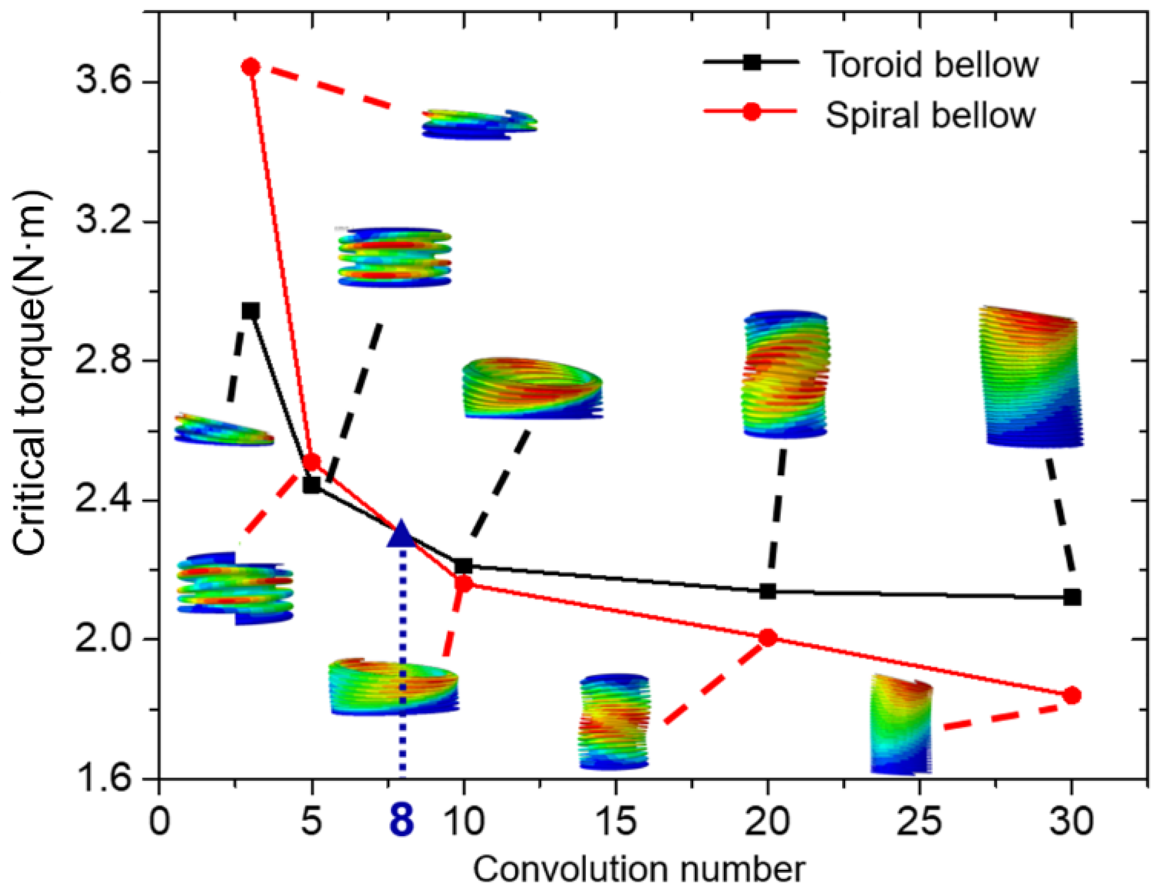
2.3. Torsional Buckling Performance Influenced by Convolution Number

In this section, the influence of the convolution number on torsion buckling behaviors of toroid and spiral bellows were studied. When convolution number n was 3, 5, 10, 20, and 30 (other structure parameters are the same as the standard bellow model, such as convolution pitch q , wall thickness d , convolution depth h , outer radius R 1 , and inner radius R 0 ), relative critical torsions and buckling modes of toroid and spiral bellows were calculated through numerical simulations, and the obtained results are presented as Table 2 and Figure 7 (the method for calculating the linear critical torque value of the bellows is as presented in Section 2.2). It was seen that there were two types of buckling modes, i.e., buckling mode (Figure 8) and column buckling mode (Figure 9). When the bellows length was relatively low (convolution number was less than 10), plane instability rather than column instability occurred. In addition, the critical torque value of plane instability of spiral bellows was found to be larger than that of toroid bellows. Besides, according to Figure 8 and Figure 9, the torsional buckling modes of toroid and spiral bellows were quite similar. According to Figure 7, the critical torque values were decreased as the convolution number in the bellows was increased. When the convolution number was less than 8, the critical torque values of the spiral bellows were larger than that of the toroid bellows. However, when the convolution number was larger than 8, the critical torsional stability of the toroid bellows was higher than that of the spiral bellows. Meanwhile, the curves of both toroid and spiral bellows sharply decreased at the beginning (convolution number was less than 10), which were in plane buckling modes. Then, when the convolution number was larger than 10, the curves slowly declined and tended to be stabilized gradually due to the characteristics of column buckling modes.
When the convolution number was larger than 10, the decreasing trend of critical torque instability values was almost linear with the increase of convolution number. Since the bellows were relatively long in this case, column instability was more likely to occur than plane instability and the critical instability torque values of the toroid bellows were larger than those of the spiral bellows. This was because the structure of toroid bellows satisfied the plane cross-section assumption due to the circular cross section of the structure. In other words, the cross section was flat and the section size was not changed before and after deformation, as shown in Figure 10a. For spiral bellows, the cross section was no more circular, as shown in Figure 10b, and the deformation principle of the spiral bellows could not be described in the plane cross-section assumption under torsion load, resulting in the appearance of warping, as shown in Figure 11. Because of the reaction forces in both ends of the bellows, the warping angles of the cross-section were different in different positions, which changed the fiber length on the junction between two neighboring cross-sections, giving rise to the generation of warping stress, which relatively decreased the torsional stiffness of spiral bellows. Therefore, column instability could happen more easily in spiral bellows.

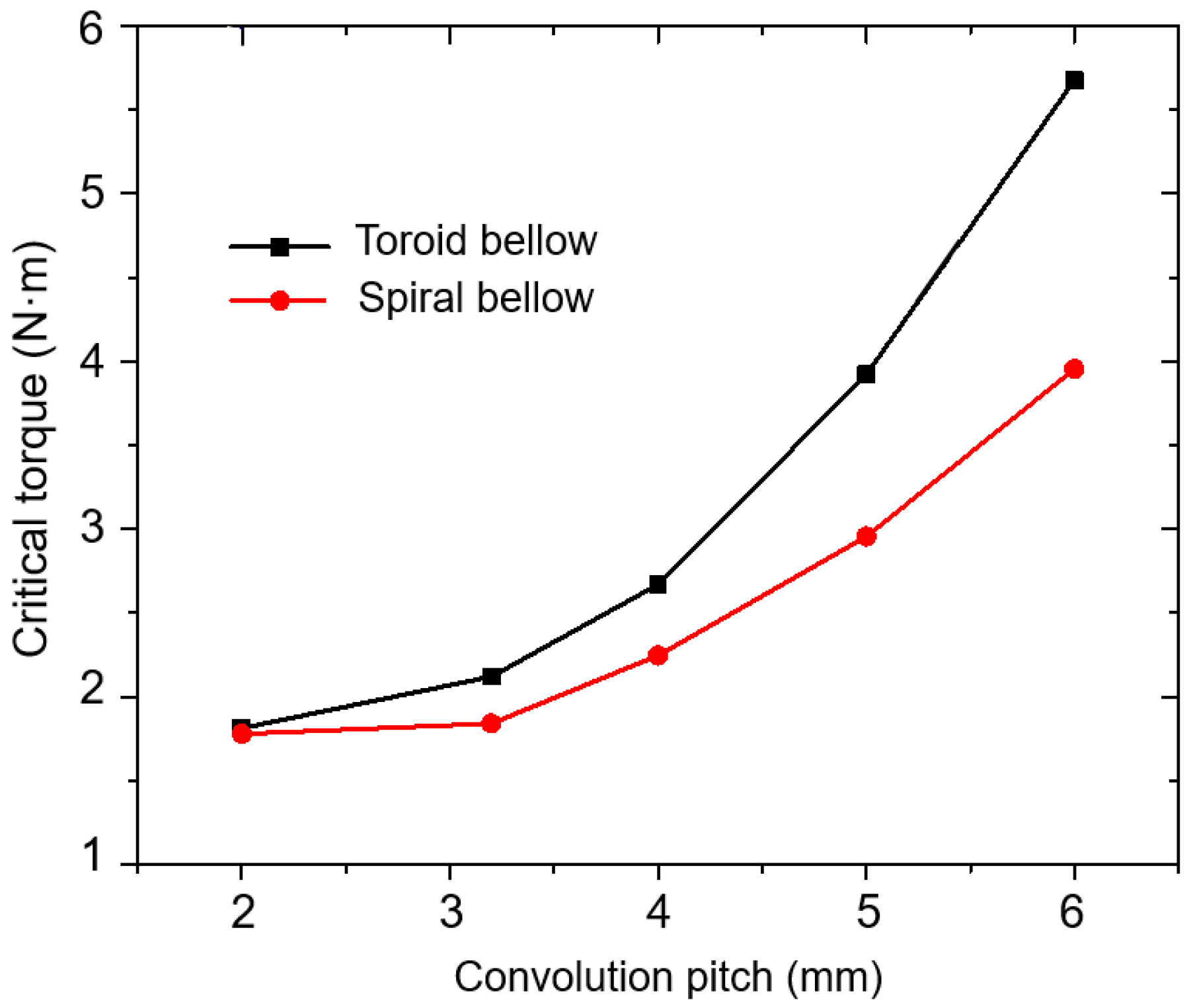
2.4. Torsional Buckling Performance Influenced by Convolution Pitch

Convolution pitch q is another important factor in the convolution structure of bellows, as shown in Figure 3, which affects the effective length and mechanical performance of bellows. To investigate the mechanical behaviors of critical buckling loads under the effect of a spiral angle, in this section, considering the actual production condition, 2.0, 3.2, 4.0, 5.0 and 6.0 mm convolution pitch of bellows (other structure parameters are the same as the standard bellow model, such as convolution number n , wall thickness d , convolution depth h , outer radius R 1 , and inner radius R 0 ) were adopted to conduct numerical simulations and analyze critical torsion angles.
The results of numerical simulations are presented as Table 3 and Figure 12, which showed that the critical torque values of toroid and spiral bellows were increased with the increase of convolution pitch and torsion instability, which were less likely to happen. In the meantime, the increasing rate of critical instability torque of toroid bellows was larger than that of spiral bellows. According to the results presented in Table 3, the increase of convolution pitch intensified the effect of spiral structure characteristics on the critical torsion angle of bellows. The reason was that longer convolution pitches and larger spiral angles of spiral bellows increased the deviation between the cross-section shape and normal circle and warping stress under torsion and decreased critical torque.

2.5. Torsional Buckling Performance Influenced by Convolution Depth

Convolution depth h is the maximum width of a single-period convolution along radial direction, as shown in Figure 3. Convolution depth determines the length of ring plate on the circumference for the same convolution pitch. Similarly, considering actual production conditions, the convolution depth h of bellows were taken as 7.5, 9.0, 10.5, 12.0, 13.5 and 15.0 mm (other structure parameters are the same as the standard bellow model, such as convolution number n , convolution pitch q , wall thickness d , outer radius R 1 , and inner radius R 0 ) to conduct numerical simulations and analyze the influence of convolution depth on torsion buckling behaviors. Figure 13 shows the trend of critical torque value with the change of convolution pitch. The results indicated that the critical torque value was decreased with the increase of convolution depth. The reason was that the axis and bending stiffness values of bellows were decreased with the increase of convolution depth, which made the bellows more flexible and more likely to become unstable. At the same time, great differences were observed in torsion stability between spiral and toroid bellows when the convolution depth h of bellows was lower than 12 mm. Additionally, an increase of convolution depth made the stability of spiral and toroid bellows more similar. When convolution depth h was larger than 13.5 mm, the critical torque of spiral bellows was almost similar to that of toroid bellows.

2.6. Torsional Buckling Performance Influenced by Wall Thickness

The requirements of strength failure under designing pressure have to be taken into consideration in the wall thickness design of U-shaped bellows. Similarly, in order to study the influence of wall thickness on the torsion buckling behaviors of toroid and spiral bellows considering actual production conditions, the wall thicknesses of FE models were set as 0.05, 0.08, 0.10, 0.12 and 0.15 mm in the numerical simulations (other structure parameters are the same as the standard bellow model, such as convolution number n , convolution pitch q , convolution depth h , outer radius R 1 , and inner radius R 0 ). The changing trend of critical torque value with wall thickness is shown as Figure 14. The results indicated that increase of wall thickness increased the critical torque value of bellows. The reason was that the bending stiffness and torsion stiffness of bellows were increased with the increase of wall thickness. At the same time, stress along the circumference and meridian directions was decreased, which could contribute to improving the performance against buckling instability of bellows.

3. Post-Buckling of Torsional Buckling Analysis of Bellows

Linear buckling analysis is an important step in solving stability problems of bellow structures. A great amount of important information on the structural buckling behaviors of bellows could be conveniently and quickly obtained by linear buckling analysis, such as critical torque values and buckling modes. However, this method still has some limitations. For some practical engineering structures, the critical torque values obtained from this method might be significantly higher than the actual buckling loads of structures, especially for thin shell structures, such as bellows. It is not safe for the bellows design to only consider a linear buckling analysis. Therefore, it is necessary to extend former linear buckling analysis methods to post-buckling analysis of bellows.
In Section 3, the post-buckling analysis under torque of toroid bellows was analyzed based on the “Riks” arc length method of simulation, and the critical torque value was calculated out. The torsional buckling experiment of toroid bellows was carried out to verify the FE model results. On this basis, the influences of geometric structure defects, such as wall thickness defect and eccentricity of bellows, on the post-buckling of bellows under torsional loads were analyzed.

3.1. Torsional Buckling Experiment

The torsion experiment system and the experiment piece of toroid bellows are shown in Figure 15. The material of the experiment piece of toroid bellows was 316 stainless steel and the structure and material parameters of the bellows were shown in Table 4. To connect the toroid bellows to the torsion testing machine, two ends of the toroid bellows were assembled with two connectors, as shown in Figure 15a. The bottoms of the connectors are circular discs with screw thread (A* and B*), connected to both ends of the bellows by bolted connection, respectively, as shown in Figure 15b. At the other end of the connectors, the cross sections of the tops are square (A and B), and the bellows can be connected to the torsion testing machine by inserted connection, as shown in Figure 15c (The two ends of the torsion testing machine were the holes with the same square cross section as the tops of the connectors, so that the tops of the connectors can just be inserted into the torsion testing machine. At the beginning of torsion, the two ends of the testing machine (A and B in in Figure 15c) automatically inwardly clamped at the same time, so that the connectors of the bellows fastened at both ends of the testing machine to prevent the bellows flying out of the testing machine due to slip. The torsion testing machine was made in Changchun Research Institute for Mechanical Science Co., Ltd., Changchun, China (CRIMS)). As shown in Figure 15d, while at torsion testing, the right end of the torsion testing machine was fixed, the left end was applied with a torsion angle, and the torque of the left end can be measured at the same time.
With the increase of torsion angle, the torque increased gradually and the relationship between torque and torsion angle of the experiment piece of toroid bellows during this process could be obtained. The torsional buckling mode of the bellows through torsion experiment is shown in Figure 16. It can be seen that when the bellows entered the torsional buckling stage, the axis of the bellows bent outward and became warped, presented as a helical line shape, consistent with the direction of the torsional load. The buckling mode of the bellows was a typical column instability, just like the torsional buckling behavior of a beam structure. The reason was that the convolution number of the experiment piece of toroid bellows was larger than 10, column instability was more likely to occur than plane instability in this case, confirming the mechanism analysis in Section 2.3 in the meantime.

3.2. Post-Buckling Analysis of Bellows

In this section, based on the experiment piece of toroid bellows in Section 3.1 and the linear buckling analysis method presented in Section 2.2, the FE model of the experiment piece of toroid bellows was established, as shown in Figure 17. The material of the FE model was 316 stainless steel, as shown in Table 4, the elasticity modulus was 193 GPa, poisson’s ratio was 0.3 and yield stress was 298 MPa. The above elastic and plastic properties of the material were set as input data separately in ABAQUS and buckling analysis of the bellows was carried out.
Similar to the boundary conditions in Section 2.2, one end (bottom) of the FE model was fixed completely. A torsional load T 0 ( T 0 was set to 1 N·m in this simulation) was applied to the other end (top), in which only the torsion angle degrees of freedom in the axis of the bellows were released. Based on the calculation method in Section 2.2, the “Buckle analysis” step was carried out to obtain the first-order buckling mode of the toroid bellows, as shown in Figure 18. At this time, the critical torque T c r in the linear buckling was 205 N·m. Then, the “Static Riks analysis” was carried out to perform post-buckling analysis [22,23,24,25,26]. The first-order buckling mode in the “Buckle analysis” step was introduced into the perfect geometric model of the toroid bellows as the initial defect [21,27,28,29,30]. Similarly, one end (bottom) of the FE model was fixed completely and a torsional load (it was set to T c r = 205 N·m) was applied to the other end (top). The critical torque and mode results of the post-buckling analysis of the toroid bellows could be calculated with “Riks” method [21,22,23,24,25]. The angle-torque curve and post-buckling mode of the toroid bellows are shown in Figure 19 and Figure 20, respectively.
Figure 19 shows the relationships between the torsion angle and torque of the bellows in different stages through FE model prediction and experimental verification. During the period of “OA” in the whole buckling process, the torsion angle was smaller than 1.38° (the abscissa of point A), the bellows were in the linear elastic stage and the torque increased with the increase of the torsion angle linearly and rapidly. Point A was the last moment in the linear elastic stage, meaning that the post-buckling behavior started to be triggered and the state of the bellows was transformed from linear buckling to nonlinear buckling. During the period of “AB”, the torsion angle was between 1.38° and 2.95° (the abscissa of point B), the torque increased smoothly, and post-buckling behavior was gradually triggered. It can be seen that Point B was the maximum value point of the whole torsion angle–torque curve. The ordinate of Point B denoted the critical torque value of the toroid bellows in post-buckling, which was 113.50 N·m in FE model results (the red curve). Compared with the experimental results (The critical torque value was 109.85 N·m) obtained in Section 3.1, shown as the black dotted line, the FE model results of the toroid bellows showed a relatively accurate critical torque value and a consistent buckling instability mode. When the torsion angle was larger than 2.95°, the torque of the bellows no longer increased with the increase of the torsion angle, but decreased instead. It represented that the bellows had fully entered the torsional post-buckling stage and the structure of the bellows had been buckling failure. The reason was that manufacturing defects were inevitable in the structure of the bellows in practical engineering applications. In order to simulate the actual post-buckling behavior more accurately, the initial defects were considered in the post-buckling analysis, and it was a typical extreme point buckling process.
Table 5 compares critical torque values in different analysis methods. The error of the critical torque value of the toroid bellows in the FE model results was only 3.3%, compared with the experimental results, which meant that numerical methods in this research were relatively accurate and convenient in solving post-buckling instability problems of bellows. Due to geometric structural defects in actual bellows [31,32,33], compared with experimental results, the critical torque value in the FE model results presented the error of 3.3%, which shall be analyzed in detail in the next section.

3.3. The Influence of Geometric Structural Defects on the Post-Buckling Analysis of Bellows under Torsional Loads

In this section, the influences of geometric structural defects, such as wall thickness defect of bellows, on the post-buckling of bellows under torsional loads were analyzed. During the hydraulic forming process of bellows, U-shaped bellows presented different wall thicknesses [34,35,36,37]. In EJMA standard [5], the average wall thickness S P of bellows is calculated as:
S p = S 0 ( R 0 R m ) 0.5
where S P and S 0 are the average and nominal wall thicknesses of bellows and R m and R 0 are the average and inner radii of bellows, respectively, as shown in Figure 3.
In fact, the decrease of the wall thickness of bellows was much more complicated [27,38,39,40,41]. At the bellows peak, wall thickness was minimum, and at the trough, it was maximum. The wall thickness of U-shaped bellows significantly affected the bending stiffness of bellows and reduced their critical loads. According to references [42,43,44,45,46] on the wall thickness of bellows and communication with bellow manufacturers, it was found that the decreasing rate of bellows was generally in the range of 75% to 95% and therefore, wall thickness in FE model was set to 0.28, 0.30, 0.32, 0.34 and 0.36 mm (Design thickness was 0.38 mm, based on the FE model in Section 3). Post-buckling behavior was analyzed based on the modified “Riks” arc-length method discussed in Section 3.2, and the results were depicted in Figure 21. It was seen that bellows’ wall thickness significantly affected the ability of torsional buckling in the bellows. By decreasing the wall thickness from 0.36 mm to 0.34 mm, the curve predicted by the FE model continuously tended to an experimental curve. When the average wall thickness was 0.34 mm, the critical torque value given by the FE model was 110.84 N·m and the error was only 0.9%, compared with the experimental results. In addition, as the wall thickness of the bellows decreased from 0.34 mm to 0.28 mm gradually, the critical torque decreased greatly. Therefore, it was necessary to consider the influence of the decrease of bellow wall thickness on buckling instability while designing.

4. Conclusions

In this research, the buckling instability of lining bellows of LNG cryogenic hose under torsional loads was investigated in detail. The mechanism of mechanical analysis on torsional buckling of the bellows was carried out, and the influence of structural design parameters on stability performance was summarized. At the same time, the torsional buckling properties of toroid and spiral bellows were analyzed. In addition, the post-buckling analysis of U-shaped bellows under torsional loads was carried out by means of experiments and finite element simulation. On this basis, the effects of common defects such as thickness thinning on the torsional stability of bellows were investigated. The significant conclusions are summarized as follows:
(1)
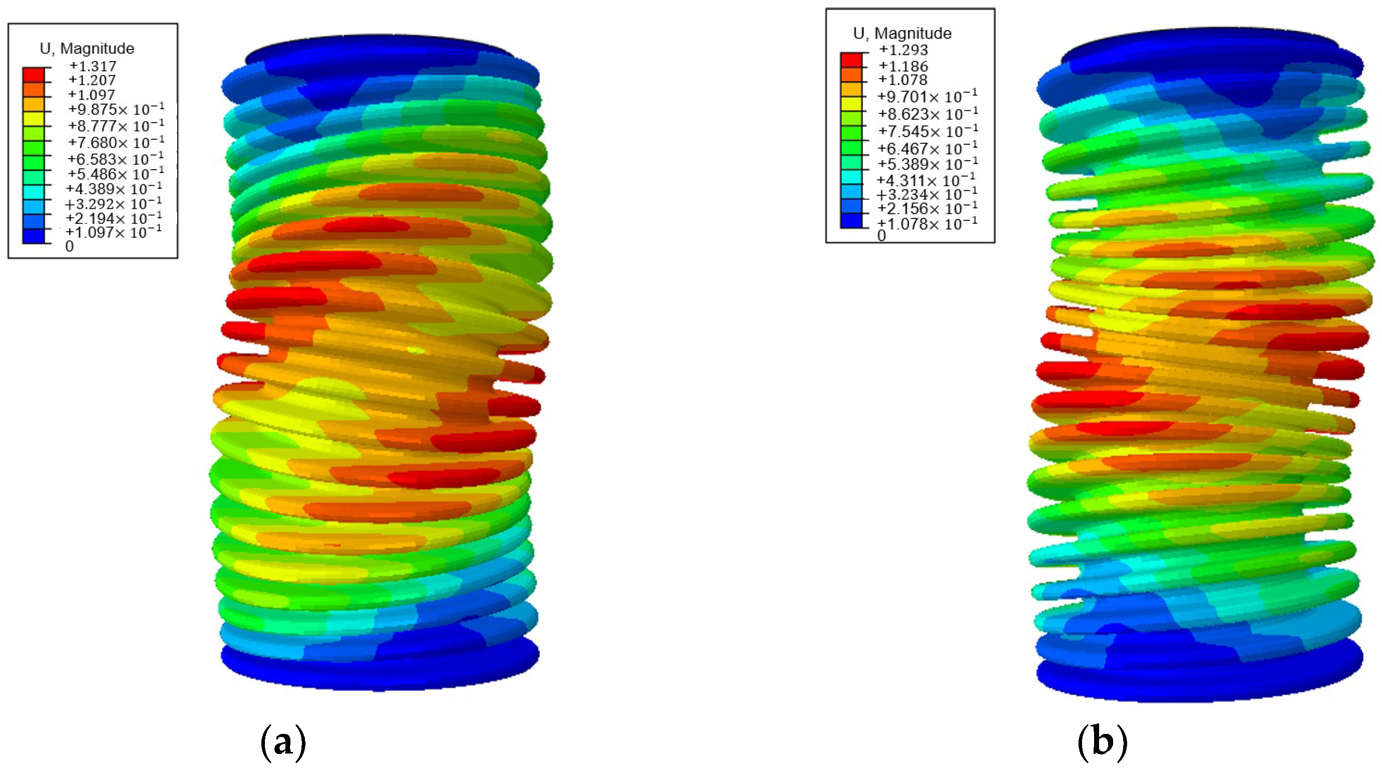
The mechanism of mechanical analysis on torsional buckling of U-shaped bellows in FLNG cryogenic hoses was carried out. The reason for becoming a spiral mode during torsional deformation of the bellows with a large slenderness ratio was that warping internal forces and tangential displacements were generated. The type of torsional buckling of U-shaped bellows at this time belonged to column instability.
(2)
There were two kinds of torsional buckling modes of bellows, including column instability and plane instability. When the slenderness ratio of the bellows was small (slenderness ratio was less than 1), the plane instability mode could occur, and the critical torque of the spiral bellows was larger than that of the toroid bellows. When the slenderness ratio of the bellows was large (slenderness ratio was larger than 1), the column instability mode could occur, and the critical torque of the spiral bellows was smaller than that of the toroid bellows.
(3)
In the sensitivity analysis of structural parameters of bellows in torsional buckling, the critical torque of the bellows decreased with the increase of convolution number or convolution depth and increased with the increase of convolution pitch or wall thickness.
(4)
As the extension of torsional buckling analysis, post-buckling behavior was analyzed by means of experiment and finite element simulation. Critical torque value in FE model was compared with experimental results, showed that the error of critical torque was only about 3.3% and the deformation of the bellows presented the same changing trends and instability modes.
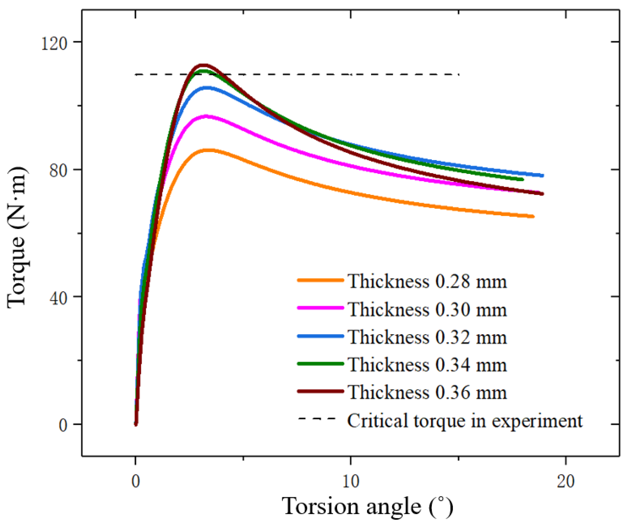
(5)
It was analyzed that the most likely reason of the error of 3.3% was the decrease of the thickness of bellows. After considering and correcting the defects of numerical model, the errors of the results obtained in this work were controlled to only about 0.9%. Therefore, the effect of the decrease of the bellows thickness on post-buckling instability performance had to be considered in practical engineering designs.
In conclusion, the mechanism of mechanical analysis on torsional buckling of U-shaped bellows as the important load-carrying components in FLNG cryogenic hoses was implemented. The results are significant references for the advanced design of FLNG cryogenic hoses. Specially, U-shaped bellows in FLNG cryogenic hoses will be under a cryogenic environment (−163 °C) during operation. The obtained mechanism in this paper would be a strong support for the thermo-mechanical coupling buckling mechanism analysis, which will be studied in future research work.

Author Contributions

Conceptualization, J.Y., X.Y., H.C. and Z.Y.; Methodology, J.Y., X.Y., H.C. and F.X.; Software, X.Y., H.C., K.Z. and F.X.; Validation, J.Y., X.Y., H.C. and Z.Y.; Formal analysis, J.Y., X.Y., H.C. and Z.Y.; Investigation, J.Y., X.Y., F.X. and Z.Y.; Resources, J.Y., F.X. and Z.Y.; Data curation, J.Y., X.Y., H.C. and Z.Y.; Writing—original draft preparation, X.Y., H.C. and F.X.; Writing—review and editing, J.Y., X.Y. and Z.Y.; Visualization, X.Y., H.C. and Z.Y.; Supervision, J.Y. and Z.Y.; Project administration, J.Y. and Z.Y. All authors have read and agreed to the published version of the manuscript.

Funding

This research was funded by the National Natural Science Foundation of China (Nos. 52271269, 52001088 and U1906233), Natural Science Foundation of Heilongjiang Province (LH2021E050), the Major Science and Technology Innovation Project in Shandong Province (2019JZZY010801), the Fundamental Research Funds for the Central Universities (3072022QBZ0703), the State Key Laboratory of Structural Analysis for Industrial Equipment, (GZ20105), State Key Laboratory of Ocean Engineering (GKZD010084).

Institutional Review Board Statement

Not applicable.

Informed Consent Statement

Not applicable.

Data Availability Statement

Not applicable.

Acknowledgments

The authors highly appreciate the financial support provided by the Natural Science Foundation. We would like to thank research center of marine equipment in Dalian University of Technology for all of their support for permitting us to use their facilities and/or resources to make this project possible.

Conflicts of Interest

The authors declare no conflict of interest.

References

  1. Snedden, N. Analysis and design guidance for the lateral stiffness of bellows expansion joints. Thin-Walled Struct. 1985, 3, 145–162. [Google Scholar] [CrossRef]
  2. Felice, R.; Nisticò, A.; Fausto, T. Marine Application of Fiber Reinforced Composites: A Review. J. Mar. Sci. Eng. 2020, 8, 26. [Google Scholar] [CrossRef] [Green Version]
  3. Krovvidi, K.; Padmakumar, G.; Bhaduri, K. Design and analysis of bellows for high temperature application as per RCC-MR. Trans. Indian Inst. Met. 2016, 69, 531–535. [Google Scholar] [CrossRef]
  4. Yang, Z.; Yan, J.; Lu, Q.; Chen, J.; Wu, S.; Wang, L.; Yue, Q. Multi-Objective Shape Optimization Design for LNG Cryogenic Helical Corrugated Steel Pipe. In Proceedings of the ASME 2016 35th International Conference on Ocean, Offshore and Arctic Engineering, Busan, Korea, 19–24 June 2016. [Google Scholar] [CrossRef]
  5. EJMA. Standards of the Expansion Joint Manufactures Association; Expansion Joint Manufactures Association: White Plains, NY, USA, 1998. [Google Scholar]
  6. Watanabe, O.; Ohtsubo, H. Stress Analysis and Torsional Buckling Analysis of U-Shaped Bellows. Des. Anal. 1989, 1, 619–626. [Google Scholar] [CrossRef]
  7. Broman, G.; Hermann, M.; Jönsson, A. Modelling Flexible Bellows by Standard Beam Finite Elements; University of Karlskrona/Ronneby: Karlskrona, Sweden, 1999. [Google Scholar]
  8. Radhakrishna, M.; Rao, C.K. Axial vibrations of U-shaped bellows with elastically restrained end conditions. Thin-Walled Struct. 2004, 42, 415–426. [Google Scholar] [CrossRef]
  9. Kondapalli, S.; Gudla, P. Investigation of stresses in U-shaped metal bellow using EJMA standards. Adv. Des. Manuf. Technol. 2017, 10, 25–35. [Google Scholar]
  10. Rieger, W. Torsion of expansion joints-first information and test results for stability properties and behaviour under stress. In Proceedings of the International Conference on Structural Mechanics in Reactor Technology, Chicago, IL, USA, 22–26 August 1983. [Google Scholar]
  11. Lu, C.; Zhou, Y.; Ye, Q. The Torsional Buckling of Bellows. J. Shanghai Jiaotong Univ. 2007, 41, 1017–1020. [Google Scholar]
  12. Dennis, K. Buckling considerations for U-shaped bellows utilized in flexible metal hoses. In Proceedings of the ASME Pressure Vessels and Piping Conference, Denver, CO, USA, 17–21 July 2005. [Google Scholar]
  13. Yang, Z.; Ying, X.; Yan, J. Study of equivalent mechanical properties of corrugated structure based on asymptotic homogenization method. J. Dalian Univ. Technol. 2021, 61, 498–505. [Google Scholar] [CrossRef]
  14. Wang, B.; Du, K.; Hao, P.; Zhou, C.; Tian, K.; Xu, S.; Ma, Y.; Zhang, X. Numerically and experimentally predicted knockdown factors for stiffened shells under axial compression. Thin-Walled Struct. 2016, 109, 13–24. [Google Scholar] [CrossRef]
  15. Hao, P.; Wang, B.; Li, G.; Tian, K.; Du, K.; Wang, X.; Tang, X. Surrogate-based optimization of stiffened shells including load-carrying capacity and imperfection sensitivity. Thin-Walled Struct. 2013, 72, 164–174. [Google Scholar] [CrossRef]
  16. Jiao, P.; Chen, Z.; Ma, H.; Ge, P.; Gu, Y.; Miao, H. Buckling behaviors of thin-walled cylindrical shells under localized axial compression loads, Part 1: Experimental study. Thin-Walled Struct. 2021, 166, 108118. [Google Scholar] [CrossRef]
  17. Jiao, P.; Chen, Z.; Ma, H.; Ge, P.; Gu, Y.; Miao, H. Buckling behaviors of thin-walled cylindrical shells under localized axial compression loads, Part 2: Numerical study. Thin-Walled Struct. 2021, 169, 108330. [Google Scholar] [CrossRef]
  18. Mohammad, R.; Amir, R.; Ali, A. Critical buckling moment of functionally graded tapered mono-symmetric I-beam. Steel Compos. Struct. 2021, 39, 599–614. [Google Scholar] [CrossRef]
  19. Mohammad, R.; Amir, R.; Ali, A. Lateral-Torsional Buckling of a Bidirectional Exponentially Graded Thin-Walled C-Shaped Beam. Mech. Compos. Mater. 2022, 58, 53–68. [Google Scholar] [CrossRef]
  20. Liu, J.; Li, H.; Liu, Y.; Li, L.; Sun, C. “Size effect” related hydroforming characteristics of thin-walled 316-L bellow considering pressure change. Int. J. Adv. Manuf. Technol. 2018, 98, 505–522. [Google Scholar] [CrossRef]
  21. Teng, J.; Song, C. Numerical models for nonlinear analysis of elastic shells with eigenmode-affine imperfections. Int. J. Solids Struct. 2001, 38, 3263–3280. [Google Scholar] [CrossRef]
  22. Angelina, C.; Priyadarsini, R. Influence of crack on the instability of GFRP composite cylindrical shells under combined loading. Appl. Mech. Mater. 2018, 877, 453–459. [Google Scholar] [CrossRef]
  23. Riks, E. An incremental approach to the solution of snapping and buckling problems. Int. J. Solids Struct. 1979, 15, 529–551. [Google Scholar] [CrossRef]
  24. Silvestre, N. Buckling behavior of elliptical cylindrical shells and tubes under compression. Int. J. Solids Struct. 2008, 45, 4427–4447. [Google Scholar] [CrossRef] [Green Version]
  25. Powell, G.; Simons, J. Improved iteration strategy for nonlinear structures. Int. J. Numer. Methods Eng. 1981, 17, 1455–1467. [Google Scholar] [CrossRef]
  26. Pang, T.; Sun, G.Y.; Ruan, D.; Huang, X.D.; Lu, G.X. Experimental Study on Crushing Resistance of Square CFRP Frusta under Axial Loading. Key Eng. Mater. 2019, 794, 194–201. [Google Scholar] [CrossRef]
  27. Hilburger, M.W.; Nemeth, M.P.; Starnes, J.H. Shell Buckling Design Criteria Based on Manufacturing Imperfection Signatures. AIAA J. 2006, 44, 654–663. [Google Scholar] [CrossRef] [Green Version]
  28. Zhang, J.; Zhou, T.; Wang, W. Buckling of a composite cylindrical shell considering mode imperfections. Acta Mater. Compos. Sin. 2017, 34, 588–596. [Google Scholar]
  29. Haynie, W.; Hilburger, M. Comparison of methods to predict lower bound buckling loads of cylinders under axial compression. In Proceedings of the 51st AIAA/ASME/ASCE/AHS/ASC Structures, Structural Dynamics, and Materials Conference, Orlando, FL, USA, 12–15 April 2010. [Google Scholar]
  30. EN 1993-1-6; Eurocode 3: Design of Steel Structures. European Committee for Standardizations: Brussels, Belgium, 1999.
  31. Wagner, H.; Hühne, C.; Elishakoff, I. Probabilistic and deterministic lower-bound design benchmarks for cylindrical shells under axial compression. Thin-Walled Struct. 2020, 146, 106451. [Google Scholar] [CrossRef]
  32. Wagner, H.; Hühne, C. Robust knockdown factors for the design of cylindrical shells under axial compression: Potentials, practical application and reliability analysis. Int. J. Mech. Sci. 2018, 135, 410–430. [Google Scholar] [CrossRef]
  33. Wagner, H.; Hühne, C.; Rohwer, K.; Niemann, S.; Wiedemann, M. Stimulating the realistic worst case buckling scenario of axially compressed unstiffened cylindrical composite shells. Compos. Struct. 2017, 160, 1095–1104. [Google Scholar] [CrossRef]
  34. Degenhardt, R.; Castro, S.G.; Arbelo, M.A.; Zimmerman, R.; Khakimova, R.; Kling, A. Future structural stability design for composite space and airframe structures. Thin-Walled Struct. 2014, 81, 29–38. [Google Scholar] [CrossRef] [Green Version]
  35. Castro, S.G.; Zimmermann, R.; Arbelo, M.A.; Degenhardt, R. Exploring the constancy of the global buckling load after a critical geometric imperfection level in thin-walled cylindrical shells for less conservative knock-down factors. Thin-Walled Struct. 2013, 72, 76–87. [Google Scholar] [CrossRef]
  36. Castro, S.G.; Zimmermann, R.; Arbelo, M.A.; Khakimova, R.; Hilburger, M.W.; Degenhardt, R. Geometric imperfections and lower-bound methods used to calculate knock-down factors for axially compressed composite cylindrical shells. Thin-Walled Struct. 2014, 74, 118–132. [Google Scholar] [CrossRef]
  37. Castro, S.G.; Mittelstedt, C.; Monteiro, F.A.; Degenhardt, R.; Ziegmann, G. Evaluation of non-linear buckling loads of geometrically imperfect composite cylinders and cones with the Ritz method. Compos. Struct. 2015, 122, 284–299. [Google Scholar] [CrossRef]
  38. Degenhardt, R.; Kling, A.; Bethge, A.; Orf, J.; Kärger, L.; Zimmermann, R.; Rohwer, K.; Calvi, A. Investigations on imperfection sensitivity and deduction of improved knock-down factors for unstiffened CFRP cylindrical shells. Compos. Struct. 2010, 92, 1939–1946. [Google Scholar] [CrossRef]
  39. Wang, Y.; Xu, B.; Sun, G.; Yang, S. A Two-Phase Differential Evolution for Uniform Designs in Constrained Experimental Domains. IEEE Trans. Evol. Comput. 2017, 21, 665–680. [Google Scholar] [CrossRef] [Green Version]
  40. Wang, Z. Influence of wall-thickness variation on non-linear behavior of U-shaped bellows calculations by iteration method of integral equation and gradient method. Int. J. Numer. Meth. Biomed. 2015, 15, 203–218. [Google Scholar] [CrossRef]
  41. Zhang, X.; Zhang, H. Static and dynamic bending collapse of thin-walled square beams with tube filler. Int. J. Impact Eng. 2018, 112, 165–179. [Google Scholar] [CrossRef]
  42. Haj-Ali, R.; Choi, J.; Wei, B.-S.; Popil, R.; Schaepe, M. Refined nonlinear finite element models for corrugated fiberboards. Compos. Struct. 2009, 87, 321–333. [Google Scholar] [CrossRef]
  43. Davalos, J.F.; Qiao, P.; Xu, X.F.; Robinson, J.; Barth, K.E. Modeling and characterization of fiber-reinforced plastic honeycomb sandwich panels for highway bridge applications. Compos. Struct. 2001, 52, 441–452. [Google Scholar] [CrossRef]
  44. Aboura, Z.; Talbi, N.; Allaoui, S.; Benzeggagh, M. Elastic behavior of corrugated cardboard: Experiments and modeling. Compos. Struct. 2004, 63, 53–62. [Google Scholar] [CrossRef] [Green Version]
  45. Yokozeki, T.; Takeda, S.-I.; Ogasawara, T.; Ishikawa, T. Mechanical properties of corrugated composites for candidate materials of flexible wing structures. Compos. Part A Appl. Sci. Manuf. 2006, 37, 1578–1586. [Google Scholar] [CrossRef]
  46. Talbi, N.; Batti, A.; Ayad, R.; Guo, Y. An analytical homogenization model for finite element modelling of corrugated cardboard. Compos. Struct. 2009, 88, 280–289. [Google Scholar] [CrossRef]
Figure 1. Typical structure of a FLNG cryogenic hose and bellows.
Jmse 10 01405 g001
Figure 2. Geometric models of the two types of U-shaped bellows; (a) toroid bellows and (b) spiral bellows.
Jmse 10 01405 g002
Figure 3. Cross-section of U-shaped bellows.
Jmse 10 01405 g003
Figure 4. FE models of the two types of U-shaped bellows; (a) toroid bellows and (b) spiral bellows.
Jmse 10 01405 g004
Figure 5. The process of first-order linear buckling of U-shaped bellows; (a) boundary conditions, (b) first-order buckling mode and (c) critical torque value.
Jmse 10 01405 g005
Figure 6. Deformation mechanism of U-shaped bellows; (a) warping internal force in the bellows and (b) torsional deformation of the bellows.
Jmse 10 01405 g006
Figure 7. Curve of critical torque versus the number of convolutions.
Jmse 10 01405 g007
Figure 8. Plane instability of the two types of bellows (convolution number was less than 10); (a) buckling mode of toroid bellows and (b) buckling mode of spiral bellows.
Jmse 10 01405 g008
Figure 9. Column instability of the two types of bellows (convolution number was larger than 10); (a) buckling mode of toroid bellows and (b) buckling mode of spiral bellows.
Jmse 10 01405 g009
Figure 10. Cross-section of toroid and spiral bellows; (a) cross-section of toroid bellows and (b) cross-section of spiral bellows.
Jmse 10 01405 g010
Figure 11. Comparison of the conditions of warping appearance; (a) no warping with circular cross-section; and (b) warping with non-circular cross-section.
Jmse 10 01405 g011
Figure 12. Curve of critical torque versus convolution pitch.
Jmse 10 01405 g012
Figure 13. Curve of critical torque versus convolution depth.
Jmse 10 01405 g013
Figure 14. Curve of critical torque with wall thickness.
Jmse 10 01405 g014
Figure 15. Toroid bellows and testing machine in the torsional buckling experiment; (a) two connectors of the toroid bellows, (b) experiment piece of toroid bellows, (c) torsion testing machine (CRIMS), and (d) toroid bellows in the testing machine.
Jmse 10 01405 g015
Figure 16. Torsional buckling mode of the bellows through experiment.
Jmse 10 01405 g016
Figure 17. The FE model of the experiment piece of toroid bellows.
Jmse 10 01405 g017
Figure 18. Linear buckling mode of the FE model.
Jmse 10 01405 g018
Figure 19. The process of the post-buckling of the toroid bellows.
Jmse 10 01405 g019
Figure 20. Post-buckling mode just at the critical torque value.
Jmse 10 01405 g020
Figure 21. Angle-torque curves of toroid bellows with different wall thicknesses.
Jmse 10 01405 g021
Table 1. Structural and material parameters of the standard bellows.
Structural Parameters (mm)Material Parameters
R1R0dhqElasticity Modulus (GPa)Poisson’s Ratio
17.0011.750.105.252.20103.000.30
Table 2. Critical torque values and instability modes of bellows with different convolution numbers.
Convolution NumberToroid BellowsSpiral Bellows
Critical Torque
(N·m)
Instability ModelCritical Torque
(N·m)
Instability
Model
32.94Plane instability3.64Plane
instability
52.44Plane instability2.51Plane
instability
102.21Column instability2.16Column
instability
202.14Column instability2.01Column
instability
302.12Column instability1.84Column
instability
Table 3. Critical torque values of bellows with different convolution pitches.
Convolution Pitch (mm)Critical Torque (N·m)
Toroid BellowsSpiral Bellows
2.01.811.78
3.22.121.84
4.02.672.25
5.03.922.96
6.05.683.95
Table 4. Structural and material parameters of the experiment piece of toroid bellows.
Structural Parameters (mm)Material Parameters
R1R0dhqElasticity Modulus (GPa)Poisson’s RatioYield Stress (MPa)
31.3825.380.386.006.00193.000.30298
Table 5. Critical torque values of the bellows in different analysis models.
Analysis MethodCritical Torque Value (N·m)Error (%)
Experimental results109.85-
FE model results113.503.3
Publisher’s Note: MDPI stays neutral with regard to jurisdictional claims in published maps and institutional affiliations.

