1. Introduction
Currently, various types of underwater vehicles such as, in particular, remotely operated unmanned underwater vehicles (ROVs) equipped with video cameras, sensors, samplers, and manipulators are actively developed and employed to efficiently address research, technological, and rescue problems in the underwater environment of the world’s oceans. These are mainly used to perform inspection and manipulative operations over small-sized objects in a limited work zone. Autonomous unmanned underwater vehicles (AUV) equipped with high-precision positioning systems [
1,
2,
3] and capable of autonomously traveling for long distances are used to address survey and search issues and inspect extended objects.
However, when conducting hydrographical, geophysical, hydrobiological, biochemistry studies, and exploring oil and gas fields, specialists usually face an important challenge of surveying large deep-sea polygons, collecting high-quality video and photographic material, profiling, finding objects, and also sampling water, soil, animals, and gas all along the route [
3,
4,
5,
6,
7]. The capabilities of modern AUV are evidently not sufficient to solve manipulation problems and perform operations that should be monitored in real time by specialists who set the goals and locations of sampling and, simultaneously, correct the vehicle’s route. Therefore, to efficiently address all these problems, it is advisable to use ROVs. However, capabilities of these vehicles are greatly limited by the tether cable, which is significantly exposed to hydrodynamic and hydrostatic factors of the surrounding aquatic environment [
8,
9]. At great depths and under strong currents, these factors cause force and torque effects on the ROV, thus hindering its movements.
To increase the mobility of ROVs, a depressor unit [
4] is used, which is an intermediate link connecting the thick, reinforced umbilical cable of the lifting/lowering mechanism with the flexible tether cable of the ROV. This common approach allows increasing the mobility of ROVs within its work zone limited by the tether cable length. However, the depressor can often collide with the bottom, thus creating an emergency situation that poses a risk of tearing the tether cable. In order to avoid such situations and ensure high-precision movement of ROVs along the intended route, it is necessary to simultaneously and concordantly control the ROV, the support vessel, and the length of the umbilical cable, continuously monitoring their locations relative to each other to prevent the depressor’s collision with the bottom. Controlling the movement of this system is an especially challenging issue in the case where the mothership does not have a dynamic positioning (DP) system.
The experiments with the work-class ROV Sub-Atlantic Comanche 18 conducted during expeditions aboard the R/V Akademik M.A. Lavrentiev in the Sea of Japan, Sea of Okhotsk, and Bering Sea have shown that sending such a vehicle and its depressor along deep-sea long-distance routes is a major challenge. At this time, operators experience great emotional and intellectual stress, because they have to make decisions based on analysis of a large amount of information and take into account the specifics of several dynamic objects at a time. Furthermore, they need to consider a range of conditions that influence the underwater operations such as currents, the bottom topography in the work zone, and the desired route for moving the ROV. As a result, the human factor often causes the quality of work to decrease and the duration of research and many technological underwater operations to increase, with emergency situations being also highly probable.
The issue of a smart support for a person controlling complex technical systems has already been successfully addressed by combining artificial intelligence, agent technologies, and human–machine interface [
10]. It is also based on methods for mathematical description of complex cause-and-effect interactions between objects of various origins, algorithms for preventing the causes of accidents in complex human–machine systems [
11,
12], methods for recognizing dangerous situations and expert assessment of the risk of dangerous approach of marine ships [
13,
14], and also new approaches to the creation of expert marine monitoring systems [
15]. However, there is an obvious need to create specialized systems for modern underwater robotic human–machine systems that take into account all the specifics of these complex and dynamic underwater objects and the conditions for operating them.
The work [
16] presents a smart emergency control system which, based on information received from the sensors and self-diagnostic tools of the vehicle’s subsystems, identifies emergency situations and makes respective changes to the missions being performed. This system is implemented using an expert knowledge database and an ontological approach. However, since this system is designed for the autonomous mode of operations and lacks an interactive graphical interface, it cannot be used without improvements to intellectual and informational support for ROV operators performing various underwater operations.
Currently, operator support systems are widely used for various ROV types [
4,
17,
18,
19,
20,
21]. The information and control system of a ROV [
4] graphically displays its spatial orientation and the configuration of the underwater multi-joint manipulator mounted on it. The article [
19] describes an intuitive interface for ROV operators based on the virtual reality technology, which creates the effect of personal presence on the ROV and increases the efficiency of controlling the vehicle’s movements. The graphical interface [
18], focused on surveying the seabed and searching for objects, helps the operator to specify the survey area and identify targets underwater. The supervisory control system [
20] was designed to significantly increase the level of automation of manipulative operations by constructing the trajectories of the manipulator’s working tool along the surfaces of working objects based on the target instructions given by the operator. The multilevel control system of multi-link manipulators of ROVs described in [
21] was designed for autonomous manipulation operations. The system uses point clouds received from machine vision systems, provides high-accuracy determination of the shape and location of the work object relative to vehicle and forms a trajectory along its surface, with possible silting, fouling, or deformation of the latter taken into account. The article [
22] presents a method for mapping the depth of an image using two stereo cameras mounted on ROVs providing stereoscopic 3D perception and augmented reality visualization to support ROV pilots in underwater manipulation tasks. Different fault-tolerant control systems [
23,
24,
25] are used to solve problems related to the reliability of ROVs continuously located in an unpredictable marine environment. The system described in the article [
23] allows you to initially detect and isolate the malfunction, as well as eliminate it. However, these systems neither provide operators with recommendations (warnings) to avoid emergency situations nor solve the problem of coordinated movement of the ROV and its depressor for a comprehensive survey of large deep-sea areas. As a result, this problem, which has an important practical implication, still remains unaddressed.
To successfully solve the problem, the article focuses on designing, implementing in software, and conducting field tests for the new multipurpose system for the smart support of activities of ROV operators that has been designed to provide simultaneous, accurate, and accident-free movements of the support vessel, the ROV, and its depressor unit
2. Control of Coordinated Movements of the ROV and the Depressor
Modern specialized ROVs support vessels such as
Akademik Golitsyn and
Mstislav Keldysh are equipped with a DP system no lower than Class 2, which makes it possible to automatically hold the vessel at a point with specified coordinates and heading angles on the sea surface when environmental conditions permit [
1].
The positions of the ROV and its depressor unit relative to each other are determined by means of the beacons of the ultra-short baseline (USBL) acoustic positioning system, with its antenna attached to the mothership. The positioning system determines the ROV’s current coordinates xv, yv, and zv and the depressor’s current coordinates xd, yd, and zd in a rectangular coordinate system (CS) xyz rigidly fixed to the vessel’s hull, with its origin located at the center of its displacement, the y axis coinciding with the horizontal, longitudinal axis of the vessel, the z axis coinciding with its vertical axis (directed downward), and the x axis complementing the other two axes to form the right-hand CS.
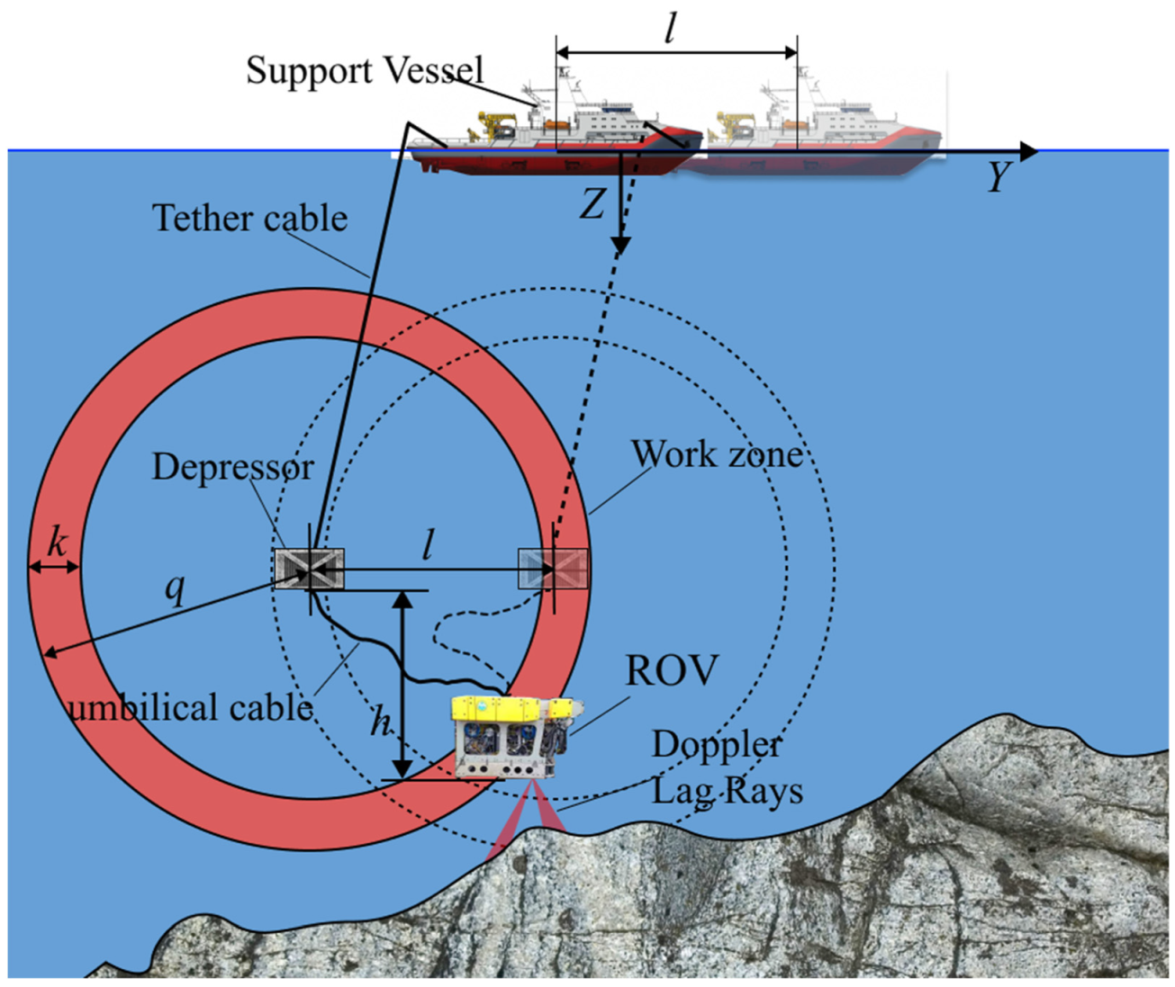
A ROV operation is only possible when a work object or target point of a route is located within the vehicle’s work zone, whose dimensions depend on the length
q of the flexible tether cable (see
Figure 1) and the location depends on the location of the depressor hanging on the rigid umbilical cable. During a ROV operation near the bottom surface, operators, in addition to controlling its movements, have to constantly give commands to the mothership crew as to how to change the umbilical cable length (see
Figure 1) with the lifting/lowering device (winch) and move the vessel in a certain direction for a certain distance. This is required to provide the greatest freedom for high-precision and accident-free maneuvering of the ROV when it is moving along a long-distance route with complex bottom topography and with a limited length of the tether cable.
For providing efficient ROV operation and avoiding the situations where the depressor and the tether cable touch the bottom, the depressor should be held above the ROV at a distance
h set by the operator (see
Figure 1) depending on the bottom topography and on the basis of experimental data and expert knowledge. To maintain the desired value
h at some degree of accuracy, the current length
p of the umbilical cable should be changed with the winch by the value
m, which can be calculated by the following expression:
where
zv is the varying depth of the ROV and
zd is the current depth of the depressor. Experimental studies have shown that Equation (1) allows calculating the desired value of
m quite accurately with different values of
p and
zd taken into account, because, under the effect of a viscous environment on the umbilical cable and depressor, this cable usually descends along an arc with variable angles to the vertical rather than vertically. As
m reaches a certain threshold value, a signal that the umbilical cable length needs to be changed again is sent to the mothership crew.
While the ROV is approaching the target point and, simultaneously, the boundary of its work zone at a distance
k (see
Figure 1), the depressor unit should be moved toward the vehicle. Simultaneously, a check is made whether the condition
is met or not. If yes, the value of the desired mothership’s movement
is calculated. Moreover the direction of this movement, defined by the desired angle
β of the mothership’s course, is calculated as follows:
where
β0 is the current angle of the mothership’s course. Moreover, this vessel can move in the direction of the angle
β (3), while maintaining the initial orientation
β0. The value
k is determined experimentally by the operator taking into account the work environment. When condition (2) is met, a warning signal that the ROV is approaching a boundary of its work zone is sent to the operator.
Information about the values m, l, and β, calculated in real time, allows operators to make correct decisions and efficiently control movements of the entire underwater system along the intended route.
For accurately controlling the depressor, the mothership should have a high-precision DP system. However, many support vessels, including the R/V Akademik M.A. Lavrentiev and the R/V
Akademik Oparin have only limited positioning capabilities (main engine and bow thrusters) that allow moving the vessel with inevitable positioning errors. The latter become especially significant in conditions of strong currents and wind impacts. Experience of marine expeditions has shown that even under limited maneuverability of such vessels, it is still possible to move the ROV depressor with an accuracy sufficient for research operations [
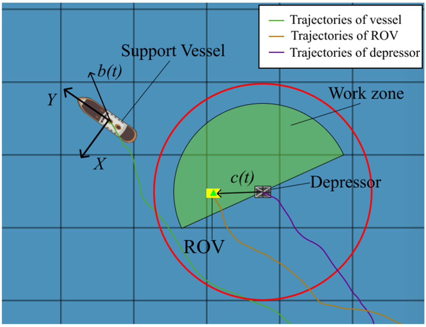
4]. However, the actual control of a vehicle moving along a long-distance route may become a serious challenge in cases where the mothership does not have an accurate DP system, even when operated by an experienced crew. In this situation, it is advisable to set the desired direction and speed of the vessel and send the ROV following this vessel, so that the latter is constantly in the front hemisphere of its work area (see
Figure 2), that is, in front of the depressor. Such an arrangement of the ROV and its depressor allows the vehicle to stop near objects of interest and have sufficient time to perform necessary operations, without requiring the mothership to stop instantly. Furthermore, during movement up a slope, this arrangement prevents entanglement of the tether cable and collisions of the depressor with the bottom.
If the ROV is located in the desired segment of its work zone, then the angle in the coordinate system
XY between the unit vector
b(t) = [
sin(
βr),
cos(
βr)]
T, which defines the current direction of vessel’s movement, and the vector
c(t) = [(
xv −
xd), (
yv −
yd)]
T, connecting the ROV with its depressor, is no greater than 90°. In this case, the following condition is met:
where
βr is the current heading angle that defines the direction of the mothership’s movement in the coordinate system
xyz. This angle is measured by the vessel’s GPS. It may differ from the heading angle
β0, which defines the spatial orientation of the vessel’s longitudinal axis, in case of wind drift and sea currents. If condition (4) is not met, a notification is given that the ROV needs to be sent to the desired segment of its work zone. In this case, the length
m of the umbilical cable is calculated by Equation (1), but the value
h (see
Figure 1) should be variable and determined on the basis of experimental observation and expert knowledge, taking into account the fulfillment of condition (4), and also taking into account the roughness of bottom topography determined by the absolute Doppler velocity log using the method described in the work [
26].
3. Features of the Software Implementation of the Support System for Operators
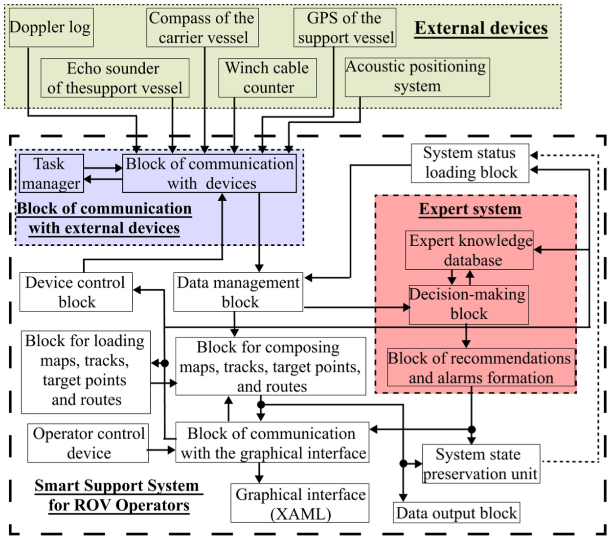
In this work, we present an architecture of the smart support system for ROV operators (shown in
Figure 3) that provide them with real-time visual recommendations and warnings based on expert evaluation of information received from various sensors and positioning systems of different manufacturers. The software implementation of this system is developed in the Net Framework environment based on the approach proposed in [
4]. For the convenience of connecting various sensors and devices to the system, its structure includes a block of communication with external devices (see
Figure 3) which asynchronously performs data transmission and processing.
The diagram for the classes of this block is shown in
Figure 4. Methods for transmitting and processing data with certain devices are available in the classes SonarDyne, WinchCable, TrackLink, etc., for which the basic class is the abstract ACDevice, implementing the methods (ClosePort(), GetActions(), etc.) and fields (actionList, name, etc.) common to all devices. Methods that should be fulfilled asynchronously in separate streams are defined in the class of each device. For this, a collection of ActionList objects of the type ActionInfo is created. Fields of this type store information about the method that should be fulfilled asynchronously, and also information required for the task manager (TaskManager) to control the process of asynchronous fulfillment of this method.
The designed smart support system for operators interacts with external devices via the DeviceControl class, whose methods allow the creation of classes of certain devices and the running of their internal methods in separate streams by means of the task manager. This makes it possible to minimize the machine time spent for waiting for data to arrive, and also to control the performance of the methods for processing this data.
The processed data from the devices are sent to the data management block (see
Figure 3), which redistributes them to other blocks. In particular, the coordinates of the acoustic beacons and the mothership are transmitted to the block for composing maps, tracks, target points, and routes, which generates tracks and filters them for further transmission to the block of communication with the graphical interface, composes maps of work zones, and also determines and plans the routes of the ROV and the mothership. The data management block also generates information about the relative positions of the mothership, the ROV, and its depressor for its further transmission to the expert system. The block of communication with the graphical interface is responsible for processing operator’s commands when interacting with the graphical interface, and also for updating it during the operation of the system.
Calculation of the values
m (1),
l,
β (3), and
h, which define the desired relative position of these objects, is implemented in the decision-making block. In this case, the variable
h is generated by the same block using formalized estimates stored in the expert knowledge base that determines the conditions for performing certain underwater operations. These estimates are set by operators or determined automatically on the basis of information received from external devices (see
Figure 3). In this case, accumulated knowledge about the consequences of selecting a certain value
h is taken into account. In addition, according to the diagram shown in
Figure 3, the decision-making block compares the current data received from the sensors and external devices with the data from the database of formalized safety limitations: emergency tension of the tether cable, rough seabed topography, possible contact of the depressor with the bottom or the ROV, the vehicle going beyond the desired sector of the work zone, etc. In this case, the probability of emergency situations is identified, and recommendations and signals are generated for operators accordingly.
The smart support system for ROV operators has the option to save maps, tracks, target points, and routes for customers of underwater operations. These can also be uploaded to the system for performing repeated ROV dives in order to search for and further inspect previously found underwater objects. These functions are implemented in the data output and upload blocks, respectively.
The possibility to save and load the system states was also implemented. Moreover, each change in its state can be automatically saved to a file: various data received, commands of the ROV operators, signaling, etc. This option makes it possible to subsequently analyze the processes of already completed ROV dives in order to identify errors both in the system operation and in operator’s actions.
These functional features of the designed system allow substantial improvements in the quality and speed of expensive underwater operations. This has been confirmed by field studies of the created system in actual marine expeditions.
4. Study of the Smart Support System for ROV Operators
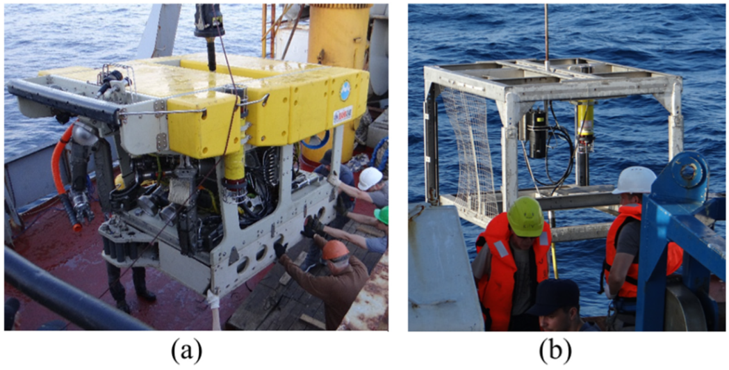
An experimental field study of the designed smart support system for ROV operators was carried out during deep-sea research expeditions of the NSCMB FEB RAS in cooperation with the Institute of Marine Technology Problems FEB RAS aboard the R/V Akademik M.A. Lavrentiev in July–August 2019 (research cruise No. 86) and in July–August 2021 (research cruise No. 94) to study the seamounts and guyots of the Emperor Chain (northwestern Pacific Ocean), and also in June–July 2018 (research cruise No. 82) to study the deep-sea ecosystems of the Bering Sea. The system was implemented for the ROV of the light working class Sub-Atlantic Comanche 18 (shown in
Figure 5a) with the depressor (see
Figure 5b).
The designed system was deployed in each ROV dive, which allowed operators to plan the routes of the vehicle and the mothership, set target points, or indicate the positions of underwater objects both by inputting geographical coordinates and using marks in the downloaded map of the work zone. During underwater operations, the system’s option to mark found underwater objects and observed marine organisms with special markers and captions that identify them was actively used. The graphical interface displayed added numerical markers and the current ROV coordinates, as well as entries with ID captions in the list of target points, in the work zone map (see
Figure 6). Simultaneously, the system added a record to the dive log file containing the coordinates of the object, its depth, ID caption, and also the time and date. These records made it possible to return to the previously discovered underwater object for its re-examination during the current or any other dive. Thus, the survey of the detected objects was greatly simplified.
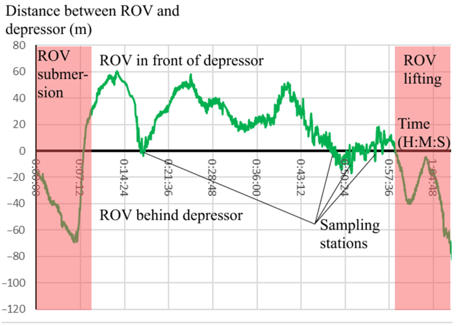
On the basis of information received from the Sonardyne’s Fusion USBL acoustic positioning system, as well as from the mothership’s GPS, the designed support system displayed the tracks of movements of this vessel, the ROV, and its depressor using a graphical interface. The tracks analysis (see
Figure 7) shows that the ROV was in front of the depressor when moving along the route and this arrangement allowed the ROV to stop and have time to collect samples.
The system provided an option of filtering these tracks with an exponential filter and manually adjusting its filtration coefficient. During the underwater operations, the tracks were saved to log files, whose format made it easy to upload them to various programs for building 3D surfaces and topographies, including those of the seabed.
The warnings and recommendations to ROV operators, generated by the program, allowed the complete avoidance of emergency situations. Furthermore, the option of saving and loading its states, implemented in the system, made it possible to analyze errors in the operation of the system and in the operators’ actions and take measures to prevent them. Data were also collected including operator commands; changes in state vectors of the ROV and support vessel; generated warnings, alarms, etc. The data obtained made it possible to expand the expert knowledge base and specify the critical values of estimates of individual parameters and their combinations.
The most interesting results were obtained in the 2018 expedition. The expedition was aimed to survey the ecosystems of hydrothermal vent fields on the Volcanologists Rise and the Piip Seamount, and also the Bering Sea shelf and the continental slope of Chukchi Peninsula from Cape Olyutorsky to Cape Navarin, using a ROV Comanche 18. For fulfilling the goals of the expedition, the ROV made a total of 21 dives, spent more than 150 h underwater, and traveled about 55 km above the bottom. The underwater operations were conducted at depths from 345 to 3880 m and included a survey of several slopes and summits of the Piip Seamount, a survey of continental slopes off the Chukchi coast, a search for various objects, video filming, selective collection of marine organisms, and sampling of near-bottom water, sediments, and geological rocks.
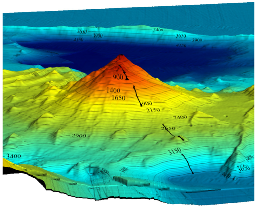
Figure 8 shows a 3D model of the Piip Seamount surface with the tracks of the ROV Comanche 18 during the survey of this volcano built using the Surfer 13 software package (Golden Software, LLC (Golden, CO, USA)). As a result of the deployment of the ROV, about 55 km of deep-sea benthic communities were studied, samples of benthic organisms and bottom sediments were collected from 128 stations (see
Figure 9), and water samples from seven stations. A total of 4735 high-resolution (5 Mpx) photographs and more than 32 h of Full HD video footage of deep-sea ecosystems were taken.
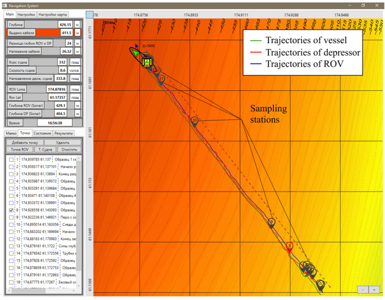
The opportunity to plan movement routes taking into account the changing work zone of the ROV, available in the system, allowed this vehicle to travel up to 6 km per one dive when searching for methane outflows on the shelf slope of Chukotka (see
Figure 10). At the same time, the ROV moved after the vessel, which was moving on a given course at a speed of 1 knot and made stops in case of detection of the desired methane outflows and hydrobionts. The warnings and recommendations, generated by the system, made it possible to significantly increase the speed and quality of expensive underwater works, simplify building the routes of ROV movements, and carry out a continuous survey of detected underwater objects.
