1. Introduction
Marine internal combustion engines are the type of heat engine most commonly used in ships of marine transport [
1]. Their functioning is impossible without fuel and air (which provide the combustion process), as well as water and oil (which support cooling and lubrication modes) [
2]. Crosshead diesel engines perform the functions of the main engines—they transfer their power to the propeller and provide the movement of the vessel. The effective power of trunk diesel engines can be converted either into the rotation of the propeller (in which case, they, like two-stroke engines, are considered the main engines), or into the rotation of the rotor of the electric generator (in which case, they provide electrical energy to the ship’s mechanisms, systems and navigation equipment, and are considered auxiliary engines) [
3,
4,
5].
Depending on the design, marine diesel engines have either two or one lubrication system. In crosshead diesel engines (which operate on a two–stroke cycle), lubrication of the cylinder group is provided by a lubrication system, while lubrication of the crankshaft and its bearings is provided by a circulation system [
6,
7]. In trunk diesel engines (which operate on a four–stroke cycle), lubrication of all elements is provided by only one circulation system [
8,
9]. In the lubricator system, oil is supplied to the walls of the diesel cylinder, where it provides lubrication, prevents sulphur corrosion, burns out, and its residues are then removed along with the exhaust gases. In the circulating system, oil is repeatedly supplied to the contact surfaces (crankshaft, bearings, connecting rod, and, in the trunk, also the cylinder group), and provides not only their lubrication, but also cooling [
10,
11].
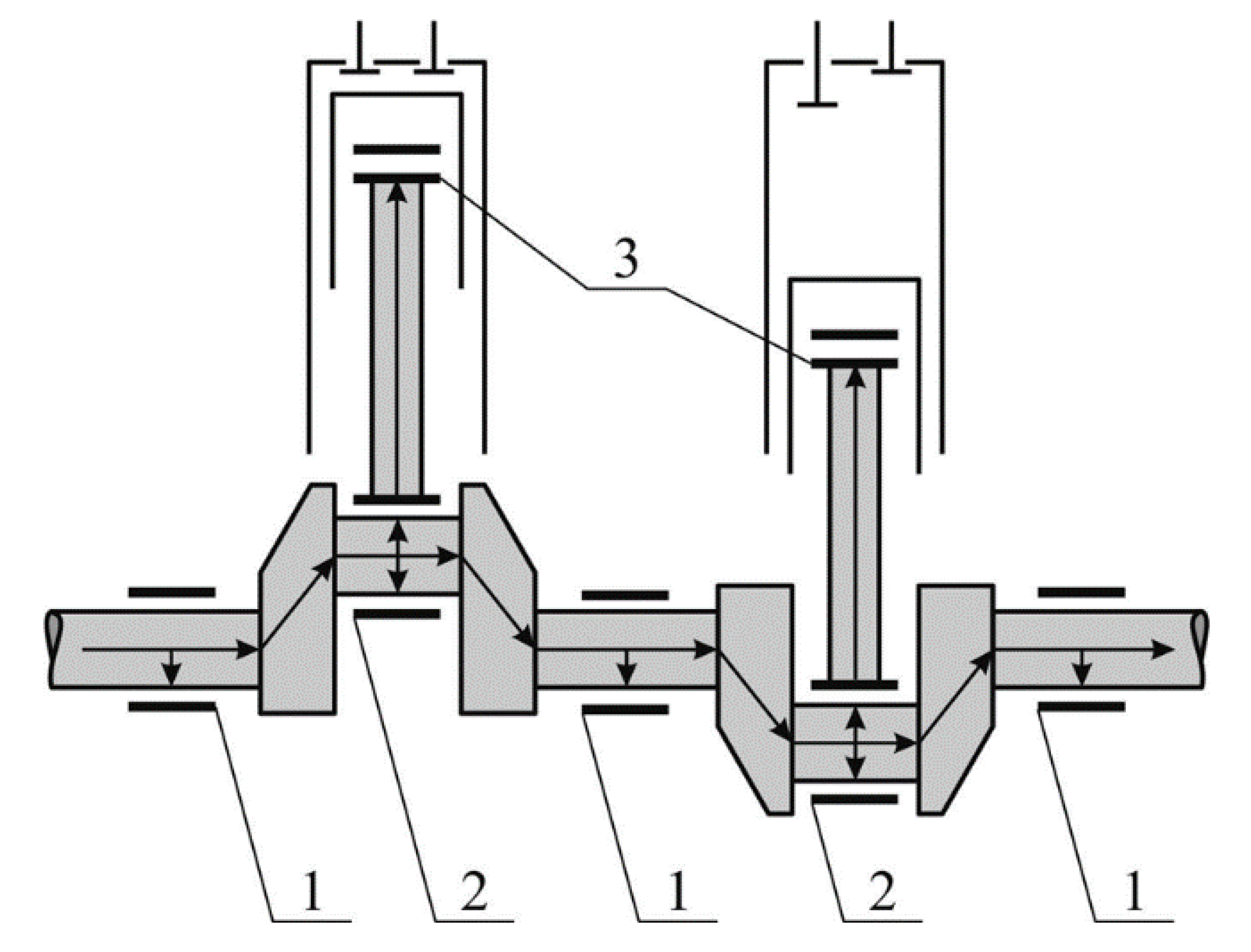
The movement of oil in the circulation system during lubrication of the frame and crank bearings occurs along the internal drillings of the crankshaft and in the head, along the drillings in the connecting rod (
Figure 1). In this case, the lubrication circuit inside the shaft and connecting rod is closed and the movement of oil inside the shaft and connecting rod occurs without leakage. Lubrication of bearing assemblies is accompanied by oil leaks from the liner–shaft interface, due to the fact that at these points the circuit becomes open, and the oil is subjected to internal (from the circulation pump) and external (from the pressure of the shaft and connecting rod) forces. The oil in the liner–shaft interface provides hydraulic tightness and prevents direct contact of this friction pair.
An increase in leakage in the liner–shaft interface reduces the damping properties of the oil, which can lead to increased wear of the bearing shells and an increase in oil consumption for waste. Metal particles that enter the oil as a result of the wear of the bearing shells move in the circulation system in the oil flow. At the same time, they contribute to an increase in the intensity of wear in friction pairs and accelerate the process of oil oxidation [
12,
13]. Waste and oxidation of the oil impair its performance, increase its consumption and reduce its life. Compensation for oil consumption for waste is provided by topping up (replenishing) oil into the diesel crankcase. The frequency and thoroughness of topping up (replenishment) depends on both the performance properties of the oil and the fuel, as well as the load and technical condition of the diesel engine (primarily tribological conjugations bearing shell–shaft and piston ring–cylinder liner) [
14,
15]. Reducing the period of replenishment or complete replacement of oil in the circulation system increases the financial costs for the operation of a ship power plant, and also (due to an increase in oil consumption for waste) is a sign of a deterioration in the environmental friendliness of a diesel engine [
16,
17].
The process of lubrication of marine diesel engines is one of the central processes that ensure its functioning, as well as its reliable and safe operation. Violation of the lubrication process (a critical decrease in pressure or a critical increase in oil temperature) can lead to an increase in thermal and mechanical stresses and an emergency situation (e.g., breakage of piston rings, piston jamming in the cylinder, or rotation of bearing shells) [
18,
19]. The importance of the lubrication process is confirmed by the following fact: in the event of a “blackout” of the vessel, one of the mechanisms that the emergency generator must ensure the continued operation of is the oil pump of the circulating lubrication system. Reliable operation of marine trunk diesel lubrication systems ensures the safe operation of the entire marine vessel [
20,
21]. Trunk diesel engines (which perform the functions of ship auxiliary generators) provide electrical energy for navigation equipment, cargo devices, and a steering gear. Even a short–term stop of these diesel engines (either during the sea/ocean crossing, or while staying in the port/at anchor) can lead to a serious accident (e.g., collision of ships, damage to the ship and the ship’s equipment, disruption of cargo operations, or environmental pollution of the sea and coastal area). Therefore, maintaining reliable and safe operation of lubrication systems for marine trunk diesel engines (as one of the main systems that ensure their operation) is an urgent applied task with critical scientific aspects.
2. Literature Review
The system shaft–bearing shell of a marine internal combustion engine refers to the standard tribological system. This system consists of two metal surfaces that are separated from each other by a layer of oil. Such a system is characterized by: composition (surfaces and their properties); internal connections (hydrodynamic or boundary lubrication / friction mode); external connections (radial and tangential forces that act from the side of the crankshaft); and functional characteristics (the presence of an oil film between the surfaces and the absence of contact between them) [
22,
23]. The engine oil that enters the shaft–bearing shell system is characterized by structural and mechanical strength and resistance to external loads. Both properties of the oil ensure reliable and safe operation of trunk–type diesel engines of marine transport vessels. Structural and mechanical strength increases the lubricity of engine oil. The acquisition of this property is especially relevant for an open lubrication circuit, when surface tension forces an increase in the lubricating layer, oil leakage decreases, and the bearing capacity of the oil layer increases [
24,
25,
26].
Ensuring reliable and safe operation of lubrication systems for trunk diesel engines of marine transport vessels is made possible by controlling either the metal surfaces (cylinder liner, piston rings, bearing shells) or the oil.
The control action on metal surfaces can be carried out:
By making them or coating them with metals with high hardness—molybdenum, chromium, copper, titanium, or vanadium [
27,
28,
29];
Drawing on them a regular microrelief [
30,
31,
32];
Changing their geometry [
33,
34,
35].
These methods provide the desired effect but have certain disadvantages. In the first case, the hardness of local sections of diesel parts (the upper part of the cylinder liner, the edges of the piston ring) increases, which reduces their wear. However, the cost of metals that are applied to the surface exceeds the cost of iron and steel [
36,
37]. The second technology reduces the coefficient of friction between the surfaces and increases the intensity of oil movement between them. This requires special equipment that provides a constant depth and the repeated identical step of applying a regular microrelief [
38,
39]. In the third case, dry and boundary are excluded, and the hydrodynamic lubrication regime in the triad is constantly provided metal–oil–metal. However, the change in the geometry of the parts reduces their strength [
40,
41]. In connection with these examples, the given technologies have a single character.
The control action on engine oil, which is used in lubrication systems for trunk diesel engines of marine transport ships, is carried out by dissolving special additives in its volume. This activates the intermolecular forces of the oil and contributes to the occurrence of additional disjoining pressure in the oil layer [
42,
43,
44]. The use of this technology requires a preliminary determination of the optimal concentration of additives in the oil, as well as the installation of additional equipment in the oil system to ensure effective dosing of the additive [
45,
46].
The above technologies have been developed and implemented for road transport, as well as for stationary energy (diesel engines and turbines of thermal and electric stations). These technologies have not been implemented with respect to marine diesel engines. First, this is due to the autonomy of the operation of vessels and their power plants, and also to the necessity of periodic repatriation of the ship’s crew. The first limits logistics (there are problems with the delivery of the required materials to the vessel), the second forces training for ship engineers on the operation of special equipment.
One of the ways to control the metal–oil–metal triad is by the application of special liquid anti–friction coatings to the metal surface [
47,
48,
49]. At the same time, the structure of oil films changes, which ensures reliable and safe operation of trunk–type diesel engines of marine transport ships.
However, comprehensive studies (which allow the establishment of a relationship between the structural characteristics of the oil and the performance characteristics of marine diesel engines) are of a single nature, and do not pursue a systematic approach to this problem.
3. Materials and Methods
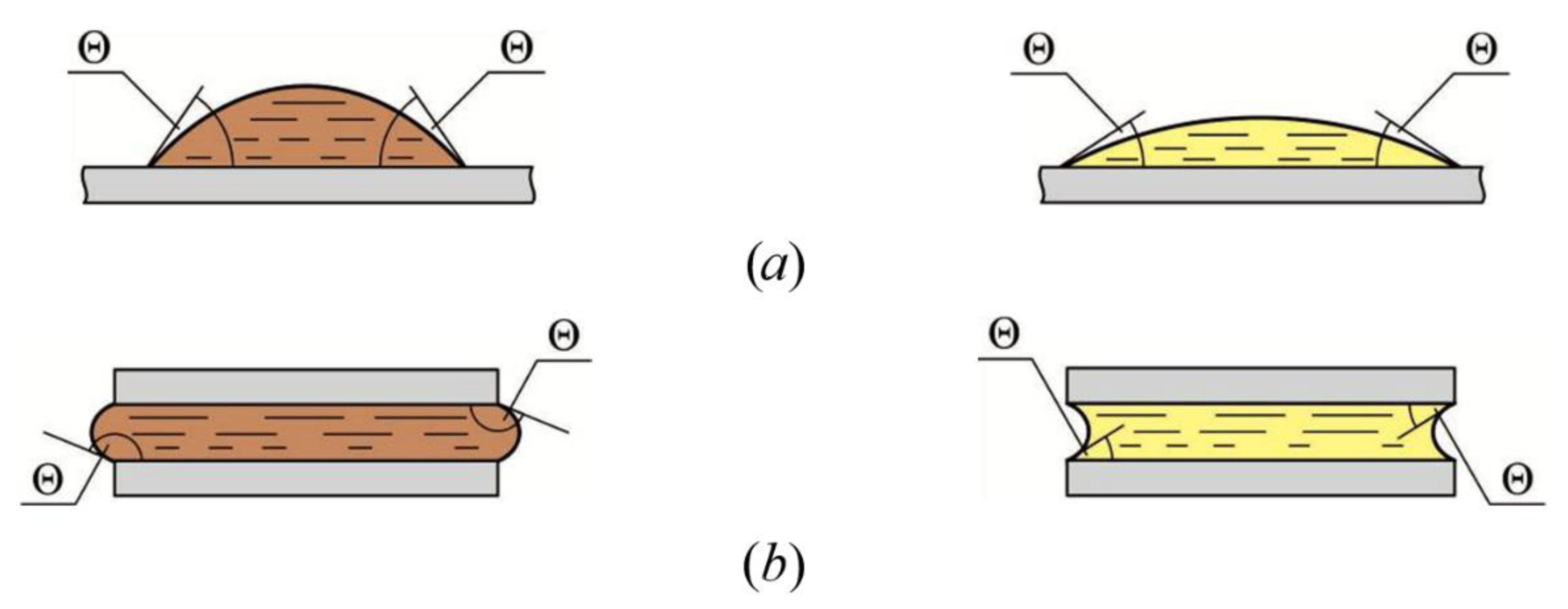
The hydraulic density of the metal–oil–metal triad depends on the structural composition and physical characteristics of the oil. These primarily include the ability of the oil layer to create disjoining pressure, as well as the power to prevent spreading over the lubrication surface [
50,
51]. The last property (as for any liquid) is determined by the surface tension and the contact angles of the oil layer. An increase in the contact angles of wetting proportionally increases the surface tension forces and prevents oil from flowing out of the tribological conjugation (
Figure 2).
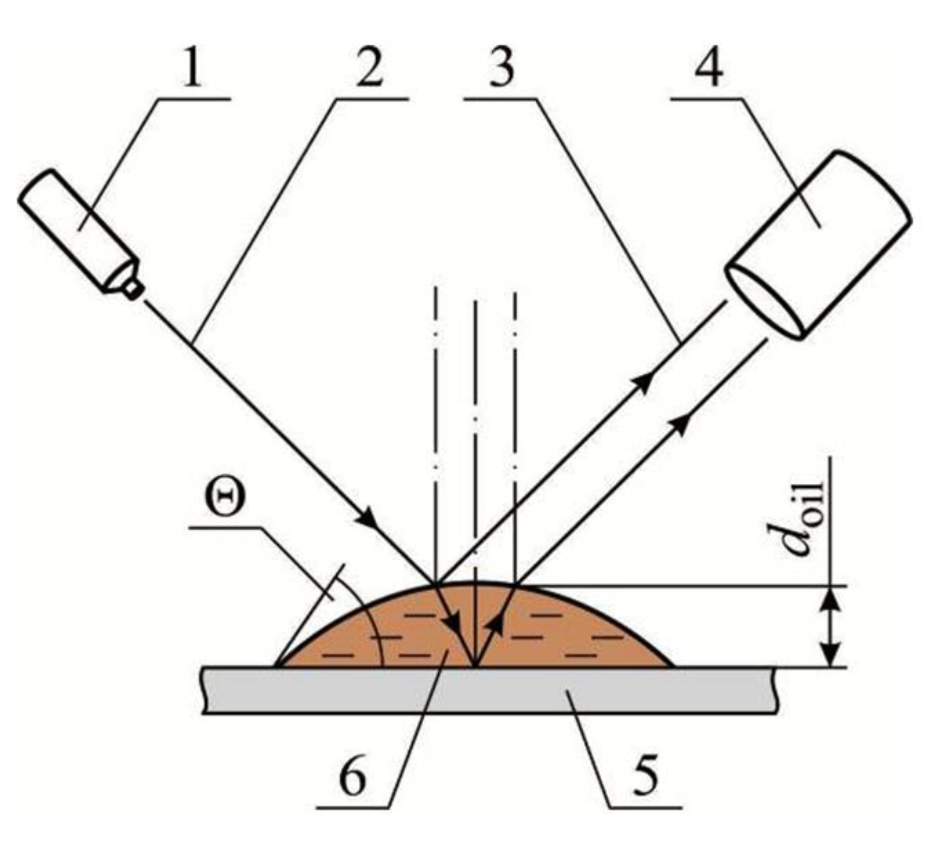
Determination of wetting angles
θ, as well as the thickness of the oil layer
doil, possibly ellipsometrically by analysing the light rays reflected from the oil and from the surface (
Figure 3) [
52].
Currently, there are electronic ellipsometric setups that allow researchers to measure these indicators with high accuracy [
53].
The objective of the study was to determine the effect of the structural characteristics of the oil layer (i.e., wetting angle and thickness) on the performance parameters of a marine diesel engine and the performance characteristics of the oil used in its circulating lubrication system. At the same time, the variables of compression pressure, the concentration of nitrogen oxides in exhaust gases and temperature of exhaust gases after the cylinder; as an oil performance characteristic—its total base number (TBN), as well as its wear and contaminant elements are measured and recorded
The studies were carried out on a Bulk Carrier marine vessel with a deadweight of 34,630 tons, the auxiliary power plant of which consisted of three of the same type of marine medium–speed diesel engines: 5L23/30 MAN-B&W Diesel Group, with the following characteristics:
Engine oil was used in the circulating diesel lubrication system Shell Gadinia AL 40 with the following main characteristics:
Oil Shell Gadinia AL 40 has been recommended by the company Shell for use in medium speed marine diesel engines and approved by the MAN-B&W Diesel Group and the shipping company’s technical management department.
Before the start of experiments on diesel engines, the parts of the cylinder-piston group (cylinder bushings, pistons, piston rings) and the crank mechanism (connecting rods and crank bearing shells) were reinstalled. This made it possible to apply a special anti-friction coating on the surfaces of all bearing shells (frame, crank, head) of one of the diesel engines—a solution of perfluoropolyether acid of the general type Rf-COOH (Rf is a fluorine-containing radical). When such a coating is deposited on the metal surface, a film up to 30 nm thick is formed, which does not affect the dislocation structure and hardness of the metal [
50]. However, this creates an additional energy barrier at the “metal-coating” interface, as a result of which the wetting angles
θ and the thickness of the oil layer
doil on the metal surface increase. The definition of these parameters (
θ and
doil) was carried out in a scientific laboratory using the setup shown in
Figure 3. Measurements were made for a volume of oil equal to 2 mL deposited on a metal surface polished to a high accuracy class. At the same time, the definition
θ and
doil was determined for two options: 1—metal surface (which, according to its characteristics, corresponded to the characteristics of bearing shells) with a preliminary application of a layer of perfluoropolyether acid Rf-COOH; 2—“standard” metal surface (without application of Rf-COOH). Contact angle values
θ and
doil oil layer thicknesses for these options are shown in
Table 1.
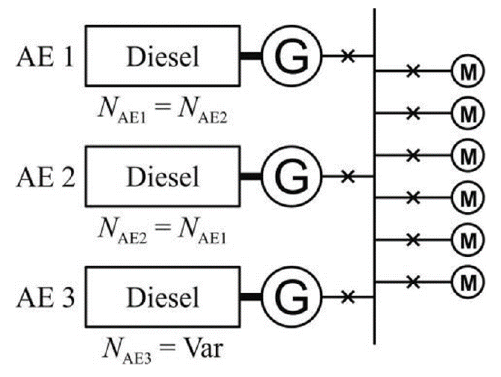
The studies were carried out during ocean crossings of the ship, the duration of which was 12–18 days. At the same time (due to the lack of shunting and mooring modes, as well as cargo operations), the operation of diesel engines occurred without an abrupt change in load [
54]. A schematic diagram of the ship’s auxiliary power plant is shown in
Figure 4. The experiments were carried out on two diesel engines, the bearing shells of one of which (AE 1 in
Figure 4) were treated with a solution of perfluoropolyether acid Rf-COOH. During the experiment, the first (AE 1 in
Figure 4) and the second (AE 2 in
Figure 4) diesel engines operated at the same load for an equal period. The total load on the ship’s power plant made it possible to operate either one or two diesel engines. In this regard, the third diesel engine (AE 3 in
Figure 4) was kept in the stand-by state.
The condition of the fuel equipment (high-pressure fuel pumps and injectors), as well as its adjustment parameters (discharge pressure, fuel supply start angle) of all diesel engines were identical. In the lubrication and cooling systems of diesel engines, the same values of temperature and pressure were maintained. Before the start of the experiments, the oil in the circulation systems of diesel engines was completely replaced. Compensation for oil consumption for waste for each of the diesel engines was carried out in the amount of 100 L through 100 h operation.
4. Results
During the experiment, the values of the following diesel performance indicators were recorded: compression pressure—
pc, gas temperature after the cylinder—
tg, concentration of nitrogen oxides in the exhaust gases—NO
X, as well as TBN of the oil [
55]. In addition, a spectral analysis of the oil was performed at the onshore laboratory in order to determine the level of impurities (Wear and Contaminant Elements) in it [
56].
The cylinder-piston group, the crank mechanism and the crankshaft of marine diesel engines are objects receiving constant monitoring of their technical condition. However, under operating conditions, frequent visual inspections of these elements are not always possible. This is primarily due to the period of continuous operation of marine diesel engines, as well as the large labour costs for their implementation. Therefore, indirect methods are used to diagnose the technical condition of the cylinder-piston group and crankshaft bearings. The most common and accessible, given the conditions of a marine vessel, is the determination of the residual base number of the engine oil (total base number—TBN); the most informative (which is carried out in coastal laboratories) is a spectrographic analysis of the amount of impurities in the oil [
57,
58].
TBN (or the currently more commonly used ‘base number’—BN) characterizes the base number and the amount of anti-corrosion additives dissolved in the oil. The value of BN is in the range of 5–100; these numbers express the number of milligrams of potassium hydroxide KOH dissolved in a gram of oil—mgKOH/gOil. The higher the BN value, the higher the anti-corrosion properties of the oil. An oil with a high BN value (40 or more) is used in two-stroke engines as a cylinder oil. Such oil should neutralize the effect of sulfuric H2SO4 and sulphurous H2SO3 acids formed in the cylinder during fuel combustion. In circulation systems (both two and four-stroke diesel engines), oil with a BN content of 5–25 is used, since in such systems the main function of the oil is to lubricate the crankshaft bearings.
During operation, gradual oxidation of the oil occurs; this is due to the high temperatures of the parts of the cylinder-piston group, as well as the ingress of wear products (primarily various metals) and unburned fuel into the oil. At the same time, there is a decrease in oil BN, and the technical condition of diesel parts worsens (wear of cylinder liners, piston rings, bearing shells increases). The control of the technical condition of the diesel engine and the functional characteristics of the engine oil is provided using the shipboard laboratories Cylinder Scrape-Down Oil Analysis, Unimarine Cylinder Scrape-Down Oil Analysis, Shell Analex Alert, KITTIWAKE Unitor, DIGI Used Oil TBN Analysis Kit and some others that allow ship engineers to determine the value BN from the oil.
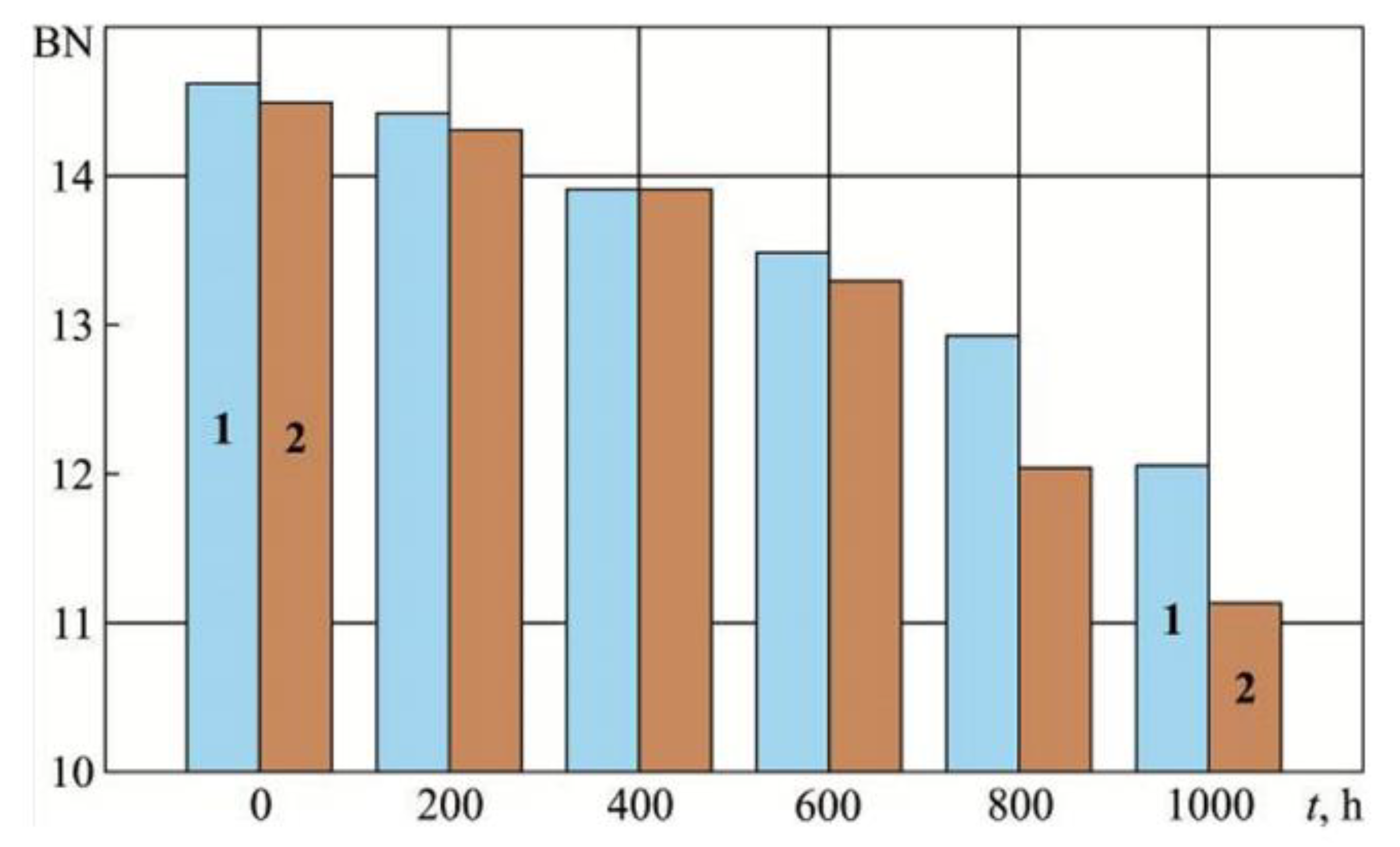
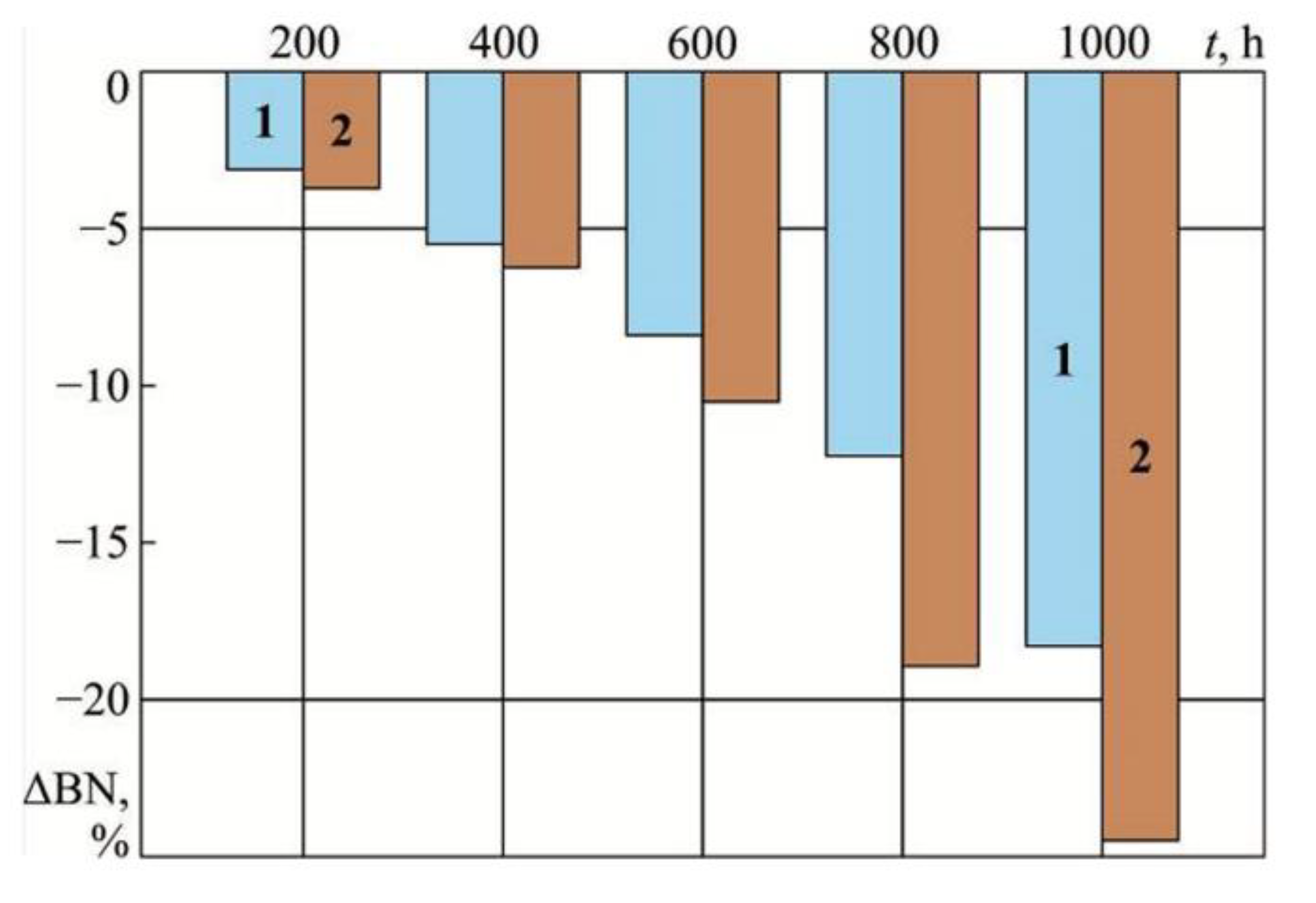
During the experiment, the control and diagnosis of the technical condition of the oil was carried out by determining BN three times with a sampling interval of 1 h. The average values of the obtained results of the experiment are shown in
Table 2.
For all measurement intervals (from 100 to 1000 h), the value BN for diesel AE 2 exceeded the same value for diesel AE 1. Comparative assessment of change BN AE 1 diesels and AE 2 can be performed by considering its relative change, which is determined by the expression:
where
BNtime,
BNnom—the value of
BN in a certain period and the nominal value (for Shell Gadinia AL 40 oil
BNnom =14.7).
Values are shown in
Table 2. Based on the values of
Table 2, nomograms were constructed showing the change
BN and Δ
BN oils Shell Gadinia AL 40 under different experimental conditions—
Figure 5 and
Figure 6.
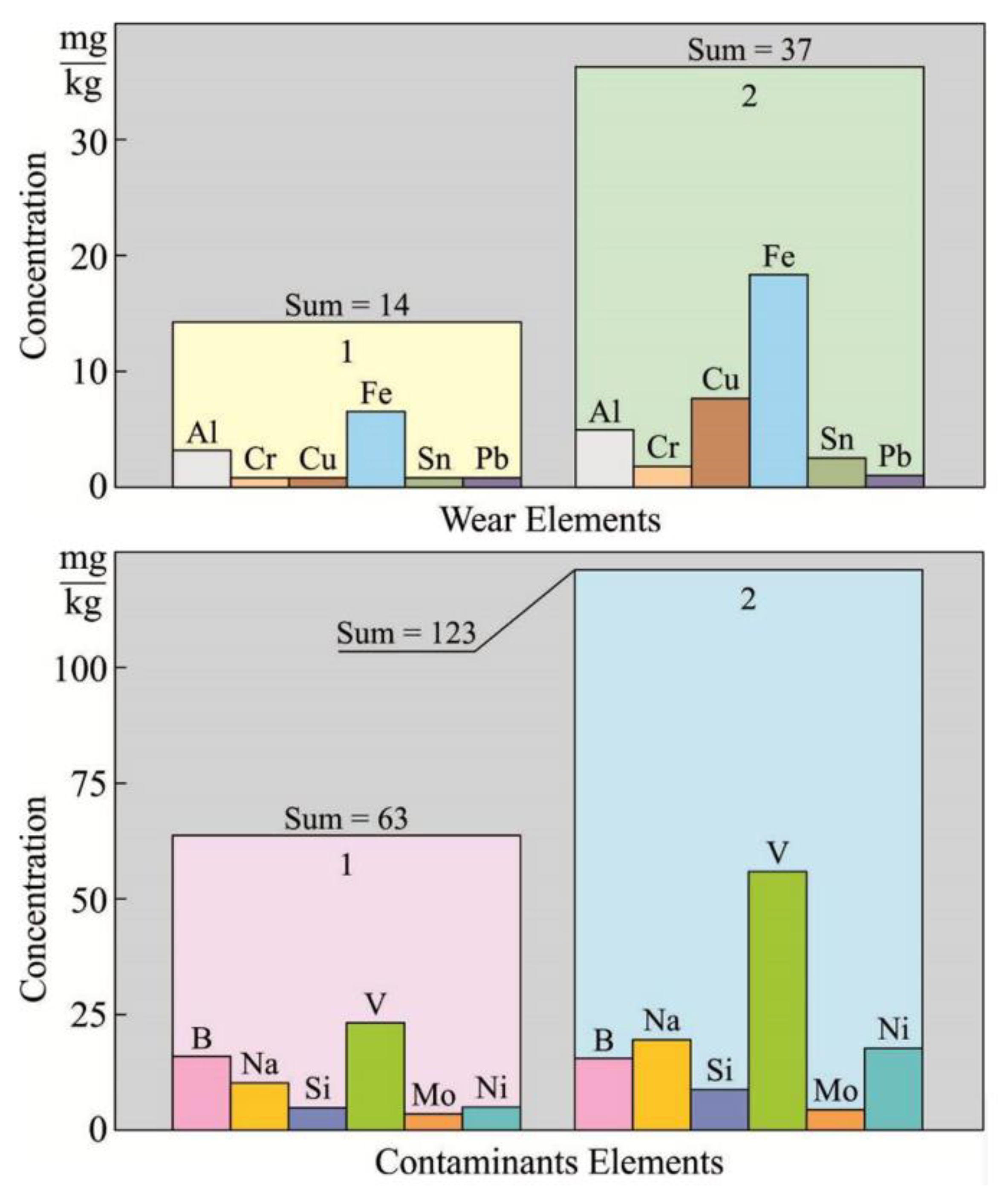
For a better assessment of the condition and determination of the functional characteristics of engine oil, its spectral analysis is performed. This determines the amount of various chemical elements that enter the oil as a result of fuel combustion, wear of diesel parts, and also as a result of direct oxidation of the oil itself. Some of these elements (in accordance with their functional action) are classified as Wear Elements, and some are classified as Contaminant Elements. Results of spectrographic analysis of oil Shell Gadinia AL 40 after 1000 h of operation in a diesel circulation system 5L23/30 MAN-B&W Diesel Group are shown in
Table 3.
Based on the results of
Table 3, nomograms were constructed, which are shown in
Figure 7.
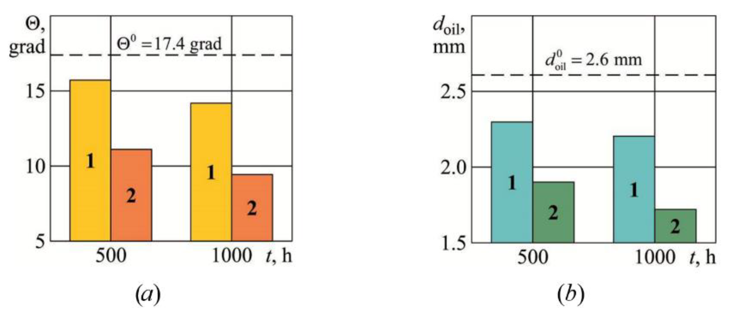
The determination of the dynamics of changes in the structural characteristics of engine oil (the wetting angle and the thickness of the oil layer) was carried out in a scientific laboratory using an ellipsometric setup (
Figure 3). In this case (similar to previous studies), an oil sample (in a volume of 2 mL) was applied to a metal surface polished to a high accuracy class. Oil sampling was carried out at three different points of the diesel crankcase when it was stopped in the interval of time intervals equivalent to 500 and 1000 h of operation. Average values of structural characteristics of engine oil (wetting angle
θ and thickness
doil) are shown in
Table 4.
According to
Table 4, nomograms were constructed showing the dynamics of changes in the structural characteristics of engine oil—
Figure 8.
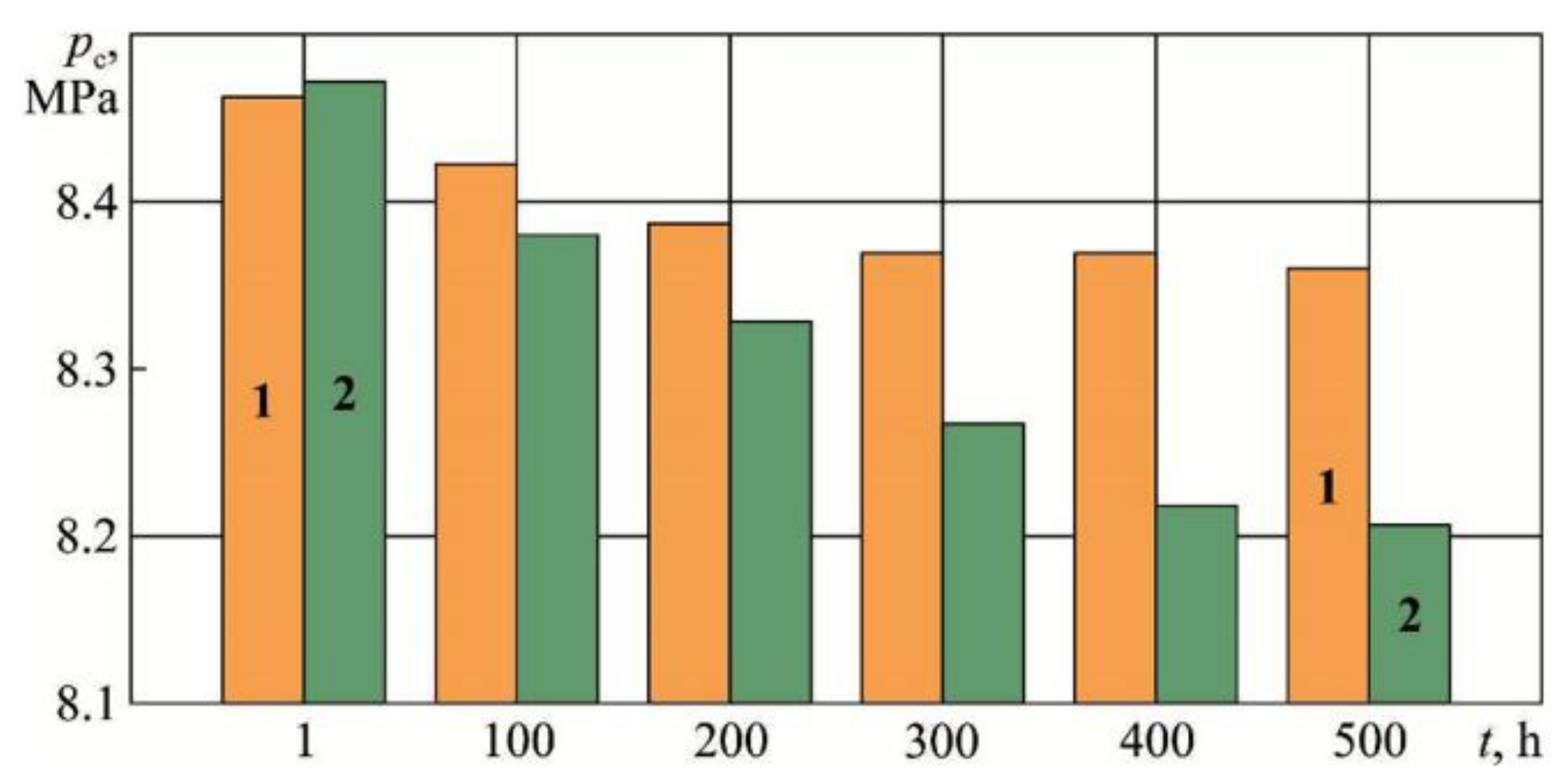
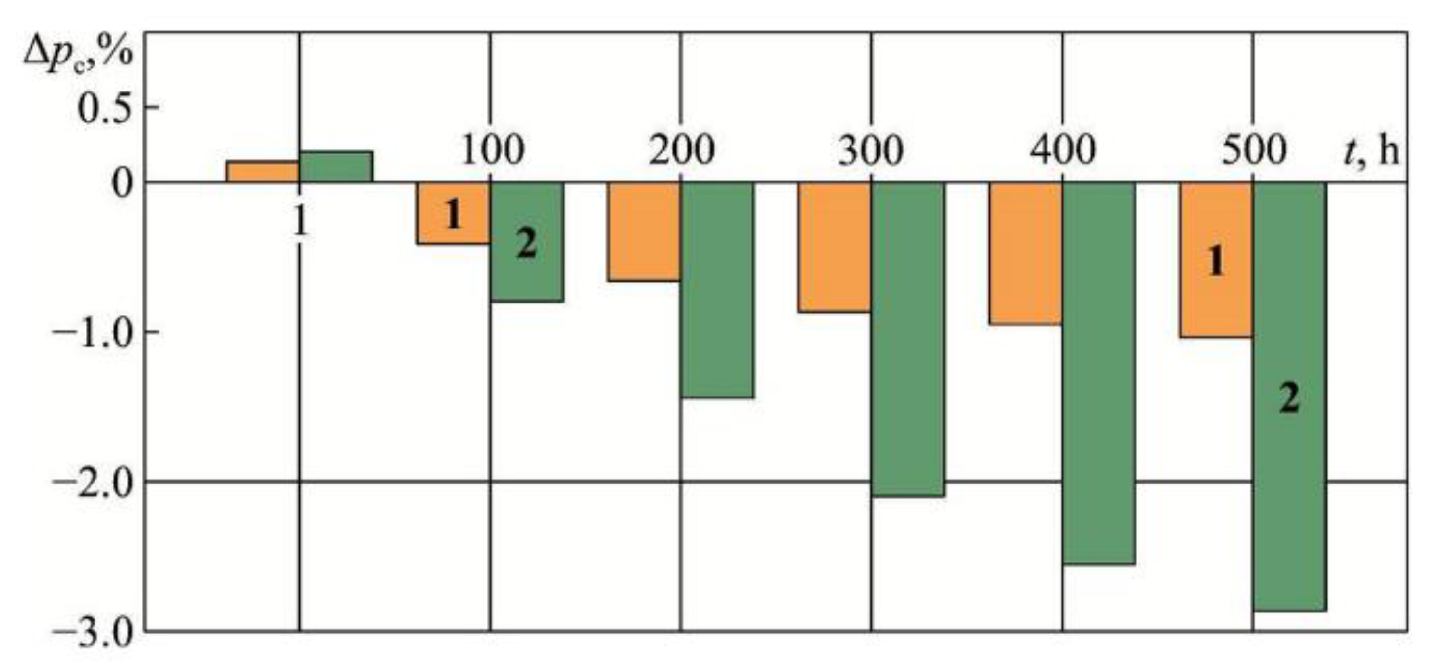
One of the indicators that characterizes the performance of a diesel engine is compression pressure. Its decrease in individual diesel cylinders indicates a deterioration in the compression properties of the piston rings, or the ingress of metal impurities on the surface of the cylinder liner. A decrease in compression pressure in all cylinders indicates a deterioration in the lubrication process.
During the experiment, the value of the compression pressure was determined using the DEPAS ship diagnostic system for each of the diesel cylinders (with the fuel supply to this cylinder turned off). Based on the obtained values, the average value of the compression pressure was calculated
. Compression pressure control was performed after the 1-st hour of diesel operation and then every 100 h of operation. At the time intervals at which the compression pressure was controlled (1, 100, 200, 300, 400, 500 h), diesel engines operated at different but equivalent loads (in the range of 450–600 kW). The DEPAS diagnostic system allows the researcher to control the parameters of the diesel engine workflow with an error ±1.0% [
59]. Obtained values for diesel AE 1 (the bearing shells of which were treated with a solution of perfluoropolyether acid Rf-COOH) and diesel AE 2 are shown in
Table 5.
According to the operating rules, the mismatch of the compression pressure in the diesel cylinders from the average value should not exceed ±2.5%. The values shown in
Table 5 indicate that this condition was met during the entire experiment. The diagrams shown in
Figure 9 visualize the results obtained, according to the values of
Table 5.
During operation, there is a gradual decrease in compression pressure. This is due to a decrease in the compression action of the piston rings and the gradual wear of the cylinder liners [
60]. The range of this reduction for diesel AE 1 for a period 1…500 h ranges from 8.46 MPa to 8.36 MPa; for diesel AE 2, from 8.47 MPa to 8.21 MPa. The intensity of the drop in compression pressure over time can be defined as the relative reduction in compression pressure by the expression:
where
,
—the average value of the compression pressure in the diesel cylinders in a certain period and the nominal value of the compression pressure, MPa.
Considering the values
that are given in
Table 5, as well as the value
, defines the values for Δ
pc, which we summarize in
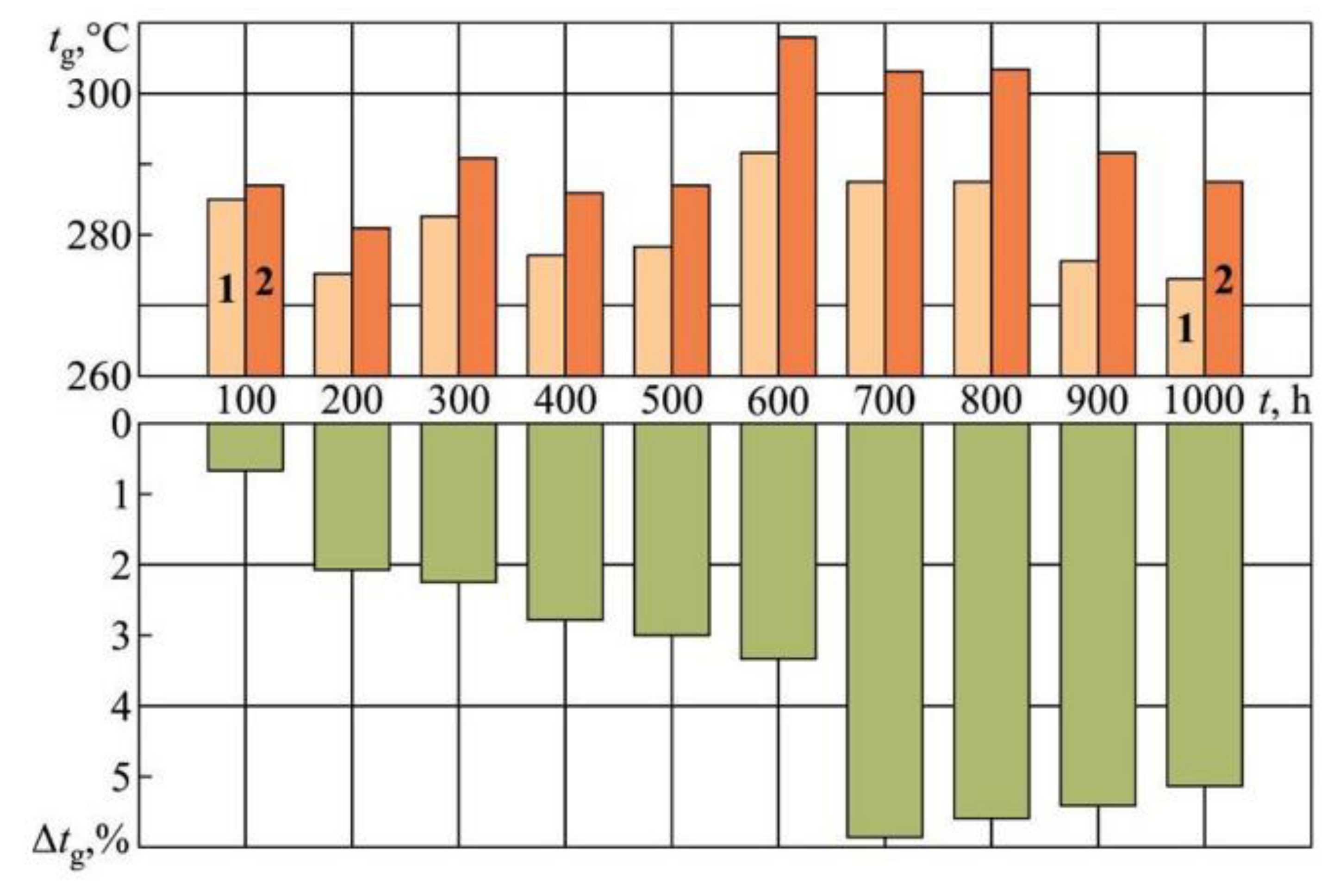
Table 6One of the experimental parameters of the diesel engine that characterizes the quality of the working process is the temperature of the gases after the cylinder
tg. An increase in its value for individual diesel cylinders indicates a deterioration in the process of fuel combustion in the diesel cylinder (in case of late injection) or an increased amount of oil falling on the cylinder walls and burning along with the fuel. The after-cylinder gas temperature control for diesel engine 5L23/30 MAN-B&W Diesel Group was carried out using the built-in diagnostic system that measures the temperature and outputs readings to the computer of the central control room. The measurements were carried out for diesel engines AE 1 and AE 2 in the range of 100–1000 h, while the diesel engines were operated at different, but equal loads. The range of their measuring was 450–600 kW. The other parameters relevant to the cooling and lubrication systems of diesel engines (i.e., oil temperature at the diesel inlet, water temperature at the diesel outlet, oil and water pressure at the diesel inlet) were maintained the same throughout the entire period of the experiment. The
tg values were determined for each diesel cylinder.
Table 7 shows the average
tg values for all cylinders. Additionally, we note that during the experiment, the deviation of the exhaust gas temperature for individual cylinders from the average value did not exceed ±10 °C.
For all measurement intervals (from 100 to 1000 h), the average gas temperature after cylinder for diesel AE 2 exceeded the same value for diesel AE 1. Comparative assessment of the change in
tg of diesel engines AE 1 and AE 2 can be performed by considering the relative change in temperature, which is determined by the expression:
where
,
—temperature of exhaust gases of diesel engines AE 2 and AE 1 for the same period of time, in °C.
Values Δ
tg are given in
Table 7. Based on the values of
Table 7, nomograms were constructed showing the changes in gas temperatures after the cylinder 5L23/30 MAN-B&W Diesel Group diesel engine under different experimental conditions (
Figure 11).
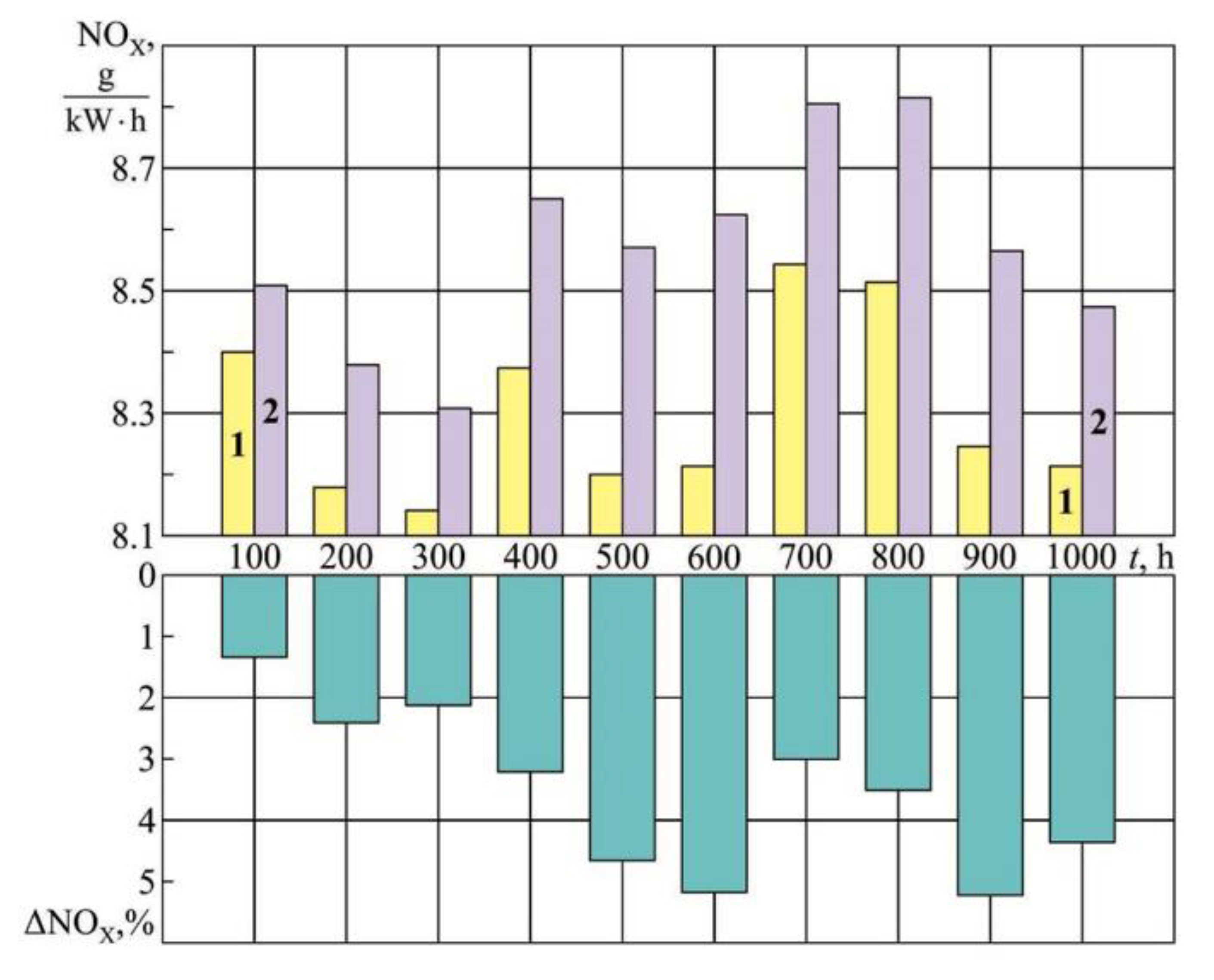
The operation of marine diesel engines is impossible without maintaining their environmental parameters. One of the main environmental parameters, the value of which is regulated by the requirements of the International Maritime Organization (IMO), is the concentration of nitrogen oxides in exhaust gases—NO
X [
61,
62]. The IMO provides a tiered approach to NO
X emissions depending on the ship’s year of construction: Tier I—for ships built before 2000; Tier II—for ships built before 2011; Tier III—for ships built after 2016. In accordance with these requirements, the Bulk Carrier on which the research was carried out belongs to Tier II. The concentration of nitrogen oxides in the NO
X exhaust gases of marine diesel engines (both main and auxiliary) in this case should not exceed the value
where
n is the diesel shaft speed, min
−1.
Considering the characteristics of the diesel 5L23/30 MAN-B&W Diesel Group
The concentration of nitrogen oxides NO
X in exhaust gases was controlled using a gas analyser Testo350XL (Germany). The gas analyser allows measurements in the temperature range up to 1200 °C. Testo350XL gas analysers meet the requirements of the Continuous Emission Monitoring System (CEMS) of the Environmental Protection Agency (EPA) [
63,
64]. The analysis of the exhaust gases was carried out in the gas exhaust line at a distance of 10 m from the place where the gases from the gas turbocharger exited, which complies with the requirements of the NO
X Technical Code. The measurement error of NOX emissions in the exhaust gases performed by the Testo350XL gas analyser was ±1.0%.
Definition NO
X concentrations in exhaust gases were carried out every 100 h of operation, while the diesel engines were operated at different but equal loads. The engine load during the period of measurement was 450–600 kW. The results are shown in
Table 8.
For all measurement intervals (from 100 to 1000 h) NO
X concentration in diesel exhaust gases AE 2 exceeded the same value for diesel AE 1. Comparative assessment NOx concentration in exhaust gases AE 1 diesels and AE 2 can be done by relative change ΔNOx, which is determined by the expression:
where
,
—NO
X concentration in exhaust gases AE 2 diesels and AE 1 for the same period, g/(kWh).
Values
are shown in
Table 8. Based on the values of
Table 8, nomograms were constructed showing the change NO
X concentrations in exhaust gases diesel 5L23/30 MAN-B&W Diesel Group under different experimental conditions (
Figure 12).
Additionally, we note that during experimental studies, the value concentration of NOX in exhaust gases did not exceed the maximum value regulated by IMO requirements.
5. Discussion
One of the systems that ensure the operation of marine trunk (four-stroke) diesel engines is the circulation lubrication system. A feature of the circulation systems of trunk diesel engines is that the oil in these systems provides lubrication and cooling of both the cylinder-piston group (cylinder bushings and piston rings) and the crank mechanism (head, crank and frame bearings). High temperature of the cylinder liner and piston rings (its value reaches 150–400 °C) contributes to the gradual oxidation of the oil. The same result is caused by the presence of wear particles in the oil (bushings, piston rings, bearing shells) and the ingress of unburned fuel into the oil. During oxidation, the performance properties of the oil deteriorate, and, in particular, its hydraulic density decreases. This reduces the forces of surface tension of the oil on the surface of the parts that it lubricates, which leads to the fact that the oil then flows out of the friction units (in circulation systems—from the head, crank and main bearings). In this case, the damping properties of the oil deteriorate and the wear of friction pairs increases. An increase in the forces of surface tension of the oil is facilitated by an increase in the contact angles of wetting the oil. This ensures the hydraulic tightness of the metal-oil-metal interface and prevents oil from flowing out of it. One of the ways to increase the contact angles of oil wetting is the application of special organic coatings on the friction surfaces (for ship trunk diesel engines—shells of the head, crank and frame bearings). These coatings create a special film up to 30 nm thick on the friction surface, which does not affect the geometry of the parts, but (due to intermolecular forces) creates an additional “energy barrier”. It is this phenomenon that contributes to an increase in the surface tension forces at the oil-metal interface and an increase the wetting angles of the oil.
Trunk diesel engines are part of the power plants of all sea and river vessels. At the same time (depending on the purpose and characteristics of the vessel), their number ranges from two to four. This expands the range of conditions for conducting experimental studies and makes it possible to compare their results. The presence in the ship power plant of a Bulk Carrier class ship with a deadweight of 34,630 tons of three of the same type of marine trunk diesel engines 5L23/30 MAN-B&W Diesel Group made it possible to use two of them for the experiment, while operating them in the same modes (with the same loads). At the same time, a special organic coating based on perfluoropolyether acid was applied to the bearing shells (head, frame, crank) of one of them. Preliminary studies have found that this increases the wetting angles of oil and the thickness of the lubricating layer that forms on the metal surface.
Increasing the wetting angles and the thickness of the oil layer (which is facilitated by the application of perfluoropolyether acid to the bearing shells) increases the hydraulic density in the metal-oil-metal interface and prevents oil leakage from the bearings. This reduces oil oxidation, which is confirmed by the base number—BN. For a diesel engine with “modified” bearing shells, the decrease in BN for 1000 h of operation was in the range of 14.6–12.0, for a diesel engine with “standard” bearing shells, in the range of 14.5–11.2.
One confirmation of the hypothesis about an increase in the hydraulic density of oil in metal-oil-metal interfaces is a recorded decrease in the wear of diesel bearing shells. To increase the antifriction properties, diesel bearing shells are alloyed with various elements (metals, transition metals, semimetals, nonmetals). If the lubrication process deteriorates, the wear of the bearing shells and the ingress of impurities into the circulating oil increase. A spectrographic analysis of the oil for the composition of Wear Elements and Contaminant Elements showed that for “modified” bearing shells, the concentration of all metal particles in the oil decreases: Al, Cr, Cu, Fe, Sn, Pb, Ni, as well as B, Na, Si, V, Mo. This, in our opinion, contributes to the experimentally established fact of stabilization of the structural characteristics of engine oil (contact angle and thickness of the oil layer), the operation of which was carried out in a diesel engine with “modified” bearing shells. The process of oil oxidation in this case occurs less intensively and the oil with greater efficiency (due to hydraulic density) prevents contacts in friction units.
Application of a layer of perfluoropolyether acid on the surface of the bearing shells improves the thermal power and environmental performance of a diesel engine. This is facilitated by a decrease in bearing shell wear and a decrease in oil consumption for waste (associated with an increase in the hydraulic density of the oil, a decrease in the number of oil leaks in the head bearing and a corresponding decrease in the amount of oil that enters the cylinder liner). Having less wear elements in the oil maintains the compression properties of the piston rings. This explains the higher compression pressures in a diesel with “modified” bearing shells.
Oil and metal particles entering the diesel cylinder burn together with the fuel and increase the temperature in both the cylinder and the exhaust manifold. In the first case, this contributes to the intensity of the formation of nitrogen oxides NOX; in the second case, it increases the thermal stress of the diesel engine and its gas exhaust system. When using “modified” bearing shells, their wear is reduced (at the same time, the number of metal particles that enter the diesel cylinder is reduced). At the same time, the hydraulic density of the oil increases (the amount of oil that flows out of the bearings decreases). This mechanism is what contributes to the fact that a diesel engine with such bearing shells has lower NOX emissions with exhaust gases and exhaust gas temperatures than does a diesel engine with “standard” (not “modified”) bearing shells.
The results obtained are in good agreement with data provided in a number of papers devoted to similar research [
65,
66,
67,
68,
69,
70,
71].
6. Conclusions
Engine oils used in circulating lubrication systems for marine trunk diesel engines must provide hydraulic density in the metal-oil-metal triad. This is facilitated by a structural characteristic of the oil: the contact angles of wetting. Optical studies have established that an increase in the degree of the contact angles contributes to an increase in the thickness of the oil layer that forms on the metal surface. An increase in the degree of the contact angles of wetting is facilitated by the application to metal surfaces (in particular, to the shells of the head, crank and frame bearings of marine trunk diesel engines) of special organic coatings—perfluoropolyether acid. In this case, the value of the contact angles of wetting θ increases from 17.4 to 19.6 grad, and oil layer thickness doil increases from 2.6 to 3.7 mm.
Elevated temperatures and pressures in a diesel engine contribute to oil oxidation and worsen its structural characteristics. However, at the same time, after 1000 h of operation, the decrease in the wetting angle for engine oil Shell Gadinia AL 40, which was used in the 5L23/30 MAN-B&W Diesel Group diesel engine with “modified” bearing shells, was from 17.4 to 14.7 grad, and in a diesel engine with “standard” bearing shells from 17.4 to 9.7 grad. At the same time, the decrease in the thickness of the oil layer in the first case was from 2.6 to 2.2 mm, and in the second case, from 2.6 to 1.7 mm.
Comprehensive studies have established a relationship between the structural characteristics of motor oils (wetting angles θ and oil layer thickness doil) and changes in their performance characteristics (base number—BN and various impurities that form in their volume—wear elements, contaminant elements).
For marine trunk diesel engines 5L23/30 MAN-B&W Diesel Group, it has been experimentally determined that the “modification” of bearing shells by applying an organic coating (perfluoropolyether acid) on their surface increases the contact angles of wetting θ and the thickness of the oil layer doil, and also improves the thermal power and environmental performance of the diesel engine.
At the same time, for an operating period of 500 h, the reduction in compression pressure in the diesel cylinder in the case of “modification” of the bearing shells is 1.1%, in the case of diesel operation with “standard” bearing shells—2.9%.
For different but equal loads of diesel engines for an operating period of 1000 h, a 0.7–5.8% increase in the temperature of gases after the cylinder for a diesel engine with “standard” bearing shells compared to a diesel engine with “modified” bearing shells has been experimentally established.
For different but equal loads of diesel engines for an operating period of 1000 h, a 1.3–5.2% increase in the emission of nitrogen oxides with exhaust gases for a diesel engine with “standard” bearing shells compared to a diesel engine with “modified” bearing shells has been experimentally established.
The application of special organic coatings on the surface of the head, crank and frame bearings of marine trunk diesel engines is an example of the use of nanotechnologies in ship power engineering. At the same time, its implementation is possible by ship mechanics during the repair or maintenance of diesel engines.


 ,
, 


