Article

Experimental Characterisation and Field Experience of a Reusable, Modified Polyurethane Foam for the Mechanical Clean-Up of Oil Spills on the Sea Surface

by
Daniel Niehaus
1,
Sebastian Hofmann
1,*,
Srividya Bairamangala Kumar
1,
Marko Hoffmann
1,*,
Jesús Cisneros-Aguirre
2,* and
Michael Schlüter
1
1
Institute of Multiphase Flows, Hamburg University of Technology, Eißendorfer Str. 38, 21073 Hamburg, Germany
2
Departamento de Física, University of Las Palmas de Gran Canaria, C. Juan de Quesada 30, 35001 Las Palmas de Gran Canaria, Spain
*
Authors to whom correspondence should be addressed.
J. Mar. Sci. Eng. 2022, 10(10), 1369; https://doi.org/10.3390/jmse10101369
Submission received: 5 September 2022 / Revised: 20 September 2022 / Accepted: 20 September 2022 / Published: 25 September 2022

Abstract

:
Oil spills at sea, such as the Deepwater Horizon incident in 2010, are devastating environmental hazards, especially for biodiversity in the maritime ecosystem. In order to help the restoration of coastlines, it is critical to clean the oil up quickly and efficiently with various measures, such as the use of barriers, skimmers, sorbents, dispersing agents, in situ burning, and biological agents. However, most of them still cause high remediation costs; are inefficient, non-reusable, and not environmentally friendly; lack a convenient desorption method; or are simply not yet ready to use in a real-case scenario, where high amounts of hydrocarbons must be removed. Therefore, in this work, a reusable modified polyurethane foam for oil absorption on the sea surface is presented and characterised. Due to a chemical formulation with a special co-polymer, its oleophilic properties are strongly enhanced. Laboratory soaking tests with different oils and a mixture of Louisiana sweet crude oil with artificial sea water (ASW) are conducted. To do so, a pneumatic press with adjustable pressures was used to characterise the foam’s capability to recover oil between 10 and 18 times its own weight for a period of up to 50 consecutive repetitions with a maximum saturation in less than one minute. Sequential trials with different oil mass fractions in ASW determined a decreasing content of recovered ASW with increasing amounts of crude oil, while, in all cases, the total oil recovery rate proved to be more than 90% within one’s standard deviation. Finally, practical applications of sorption methods are presented to give an idea of difficulties encountered in real remediation scenarios.

1. Introduction

Despite the Energy Transition Council’s statement at the UN Climate Change Conference in the United Kingdom in 2021 (COP26) to be “moving away from coal and other fossil fuels” [1], the demand for fossil energy sources such as natural gas and crude oil remains consistently high. The more reservoirs become depleted, the more remote exploration sites will be in delicate environments or deeper areas, which increases the risk of future accidents. Muehlenbachs et al. even report an increased incident probability of 8.5% for each 30 m of added depth in oil drilling for an average platform [2]. This became evident when, in April 2010, the oil rig Deepwater Horizon (DWH) ignited and sank in the northern Gulf of Mexico. It caused the largest offshore oil spill in the history of the petroleum industry. This deep-sea oil well blowout took place over a period of three months, releasing approximately 780 million liters of crude oil into the fragile marine ecosystem [3,4,5,6], and is still harming wildlife in the area many years later [7]. Although the International Tanker Owners’ Pollution Federation (ITOPF) reports a continuation of a long-term decline with oil spills, altogether 18 large-sized (>700 tonnes) and 45 medium-sized (7–700 tonnes) spills happened between 2010 and 2019 [8]. Just recently, in October 2021, another oil spill, which was caused by a leak in an offshore oil pipeline off the coast of Southern California, released another 470,000 L of crude oil and spread over an area of 34 km2 [9,10]. Minor coastal pollution incidents by hydrocarbons in port or near docking areas are not even recorded. In all cases, and most importantly, it is critical to contain any spill as quickly as possible to prevent further damages to the environment. Physico-chemical processes (e.g., weathering effects, evaporation, diffusion-driven spreading, or emulsification) break down the oil into smaller droplets and cause them to sink. A vertical distribution of oil throughout the water column expands the critical affected area extensively and could cause even more damage [11]. This is the reason why, among immediate response technologies such as chemical treatment (e.g., dispersants), in situ burning and bioremediation, especially mechanical recovery, are used to restrict the spread of oil and reduce the possibility of polluting shorelines [12]. Here, the most common type of containment equipment is floating barriers and sorbent materials [13,14], in combination with skimmers, they are used to get rid of the oil bulk. In the vicinity of the shore, which cannot be accessed by heavy machinery or at a decreased oil film thickness, at which skimmers become less effective [6], sorbents are the most important countermeasure for a clean-up.
Within the physical remediation method class suction, it is to differentiate between three types of sorbent materials, such as natural/organic (waste from agricultural products), mineral/natural inorganic (activated carbon, zeolites), and synthetic (polyurethane, polypropylene) [15]. Since they all differ in material structure, sorption time, sorption capacity, desorption method, and recycling time, just to name a few, numerous studies have been conducted and reviewed to investigate and compare their properties as potential remediation measures [15,16,17,18,19,20].
In the aftermath of the DWH incident, little has changed in how oil spills at sea or in coastal regions are cleaned. Although considerable progress in establishing oil sorption methods has taken place in recent years, most of the reported materials lack the combination of (i) a high reusability, (ii) a high oil recovery rate, (iii) an easy desorption method, and (iv) reasonable costs. For implementation in a real-case scenario, these are the major criteria of an efficient and effective way to clean oil spills.
Therefore, in this paper, a reusable polyurethane foam for oil absorption on the sea surface is investigated. The enhanced oleophilic property is derived from its chemical formulation with a special co-polymer. The focus of this characterisation is on the oil-recovery rate with varied squeezing forces and on the reusability of the foam. In addition to these investigations, the absorption capacity is also determined as a function of the oil type and in interaction with artificial seawater. It is demonstrated that the advanced foam material composition prevails, with a unique combination of all aforementioned advantageous characteristics that, to the author’s knowledge, has not been previously reported. Finally, deployment examples in real conditions are shown, where it proves to be a flexible, highly reusable, and cost-effective alternative to materials already in use.

2. Materials and Method

In this section, the reusable modified polyurethane foam (RMPUF) used is characterised. Furthermore, the test procedure and the hydrocarbons are presented, and, eventually, the setup for the mechanical desorption of the sponge is explained in detail. Hereby, this study focuses on the term oil recovery instead of oil uptake [19] or oil adsorbency [21], because the presented test rig represents a reliable method to verify the reusability of an adsorbent, meaning the recovered amount of oil. Hence, it may constitute a supplement to the standard test method F726-17 published by ASTM International (2017) [21].

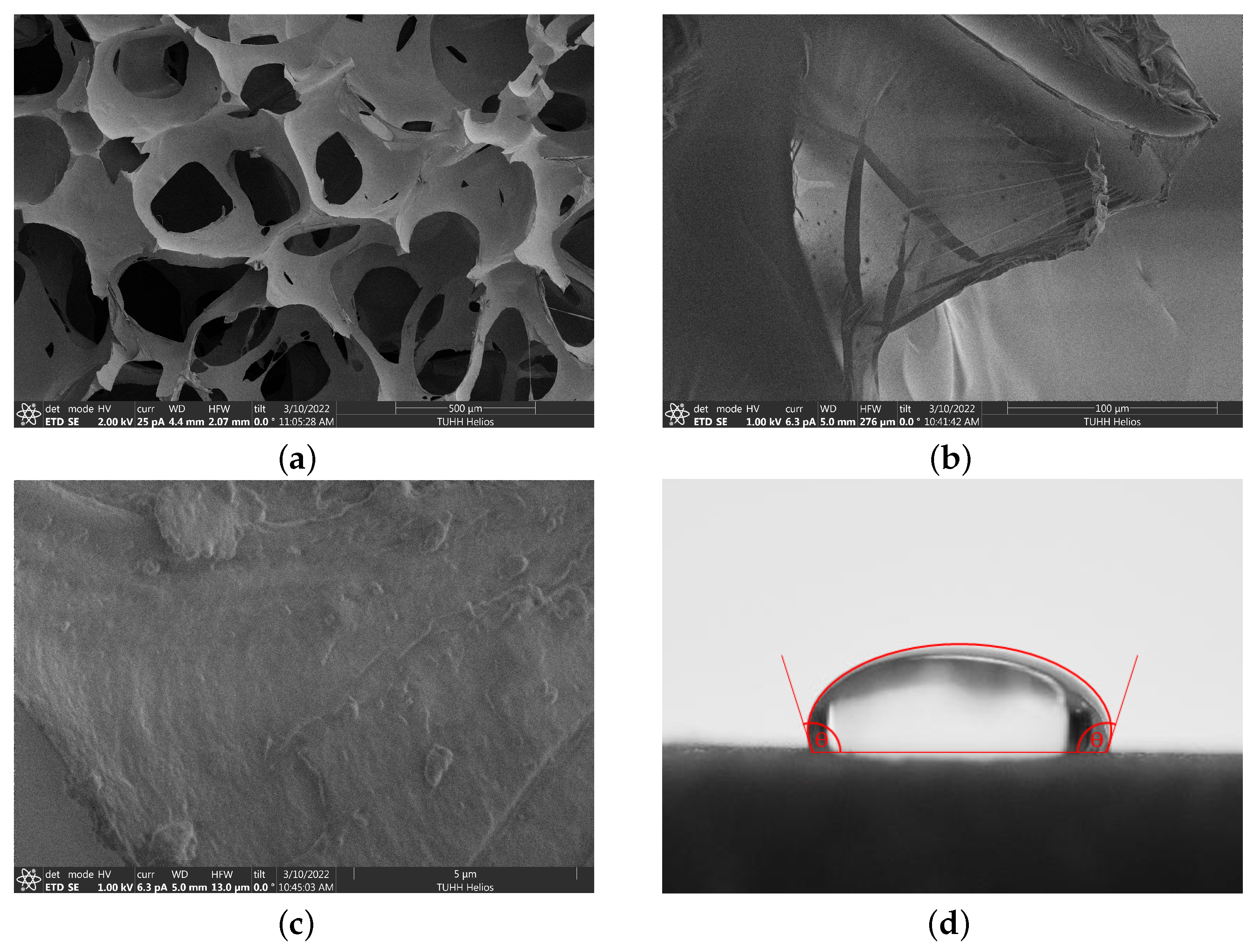
2.1. Properties of the Reusable Modified Polyurethane Sponge

The proprietary sponge material was kindly provided by the company Test1 Solutions (Brescia, Italy). To conduct an unbiased study, neither details about the manufacturing process nor its specific chemical composition are known to the authors. For the characterisation of the sponge properties (according to ASTM F726-17: Type I Adsorbent [21]), RMPUF cuboids with a length of 9.5 cm and a height of 2.5 cm are used. The weight of the sponge blocks used is m sponge = 7.22 ± 0.42 g (n = 27). From these values, a sponge density of ρ sponge = 32.00 ± 1.88 kg m−3 can be determined. Thus, the porosity ε of the sponge structure can be calculated by means of the density of polyurethane ( ρ PU = 1200 kg m−3) as
ε = 1 ρ sponge ρ PU = 0.973 ± 0.002 .
The pore structure of the sponge was examined using a scanning electron microscope (SEM, Zeiss Supra 55 VP). Figure 1a shows the macroporous structure of the sponge. It can be observed that the pore size varies from approximately 100 µm to several mm. For the purpose of imaging, this specimen was sputtered for 30 s using a gold sputtering coater (Baltec SCD 050) to obtain a better conductivity and, thus, a clearer image. The surfaces of the sample in the SEM images at higher magnifications Figure 1b,c, are not coated, as sputtering affects the surface’s fine structure. Compared to a sponge treatment in the study by Peng et al. [22], which revealed spherical particles on the surface, the RMPUF in this work shows a rather smooth surface without any major visible structural surface change (Figure 1c), despite a visible thin layer (Figure 1b), which proves the treatment with a co-polymer.
The wetting ability of the sponge with the artificial seawater (see Figure 1d) and white oil was also examined visually. When an ASW droplet is placed on the sponge material, a contact angle of θ ( 95 ± 3 ) (n = 3) can be determined. Hence, the sponge exhibits hydrophobic properties. The deposition of an oil droplet on the material resulted in a contact angle of approximately 0 , and, thus, proved the oleophilic properties of the sponge.

2.2. Properties of the Liquids

Long-chain hydrocarbons, especially crude oils, can vary greatly in terms of their material properties. Therefore, the recovery characteristics of the sponge were investigated with sunflower oil, transparent white oil (PIONIER 7467 H & R Ölwerke Schindler GmbH, Hamburg, Germany) coloured with a lipophilic dye (Sudan Red 7B, CAS 6368-72-5, Sigma-Aldrich Co., St. Louis, MO, USA) for visualization purposes, and crude oil (Louisiana Sweet Crude Oil, British Petroleum, Marlin platform, Dorado fields, Australia, see also [23,24]). Since white oil can be used as a safe oil model, which is easy to handle and offers characteristics related to crude oil, it serves as an internal reference.
The crude oil has a sulphur content of 0.26 ± 0.01 wt% and a water content of 0.44 ± 0.17 wt%. The pH value is 7.5 ± 0.1. The American Petroleum Institute degree value of the crude oil is 34.6 °API, so the oil accumulates on the water’s surface. The key factor for the wetting and absorption capacity of the sponge are the surface tension and the viscosity. For the oil used in the experiments, the surface tension was determined using a bubble pressure tensiometer (BP50, Krüss, Hamburg, Germany) and the viscosity using a rotational viscometer (Malvern Kinexus Pro, Netzsch, Erlangen, Germany), utilizing a cone and plate setup (CP1/60:PL60, cone: 60 mm diameter, 1 angle, plate: 60 mm diameter).
In Table 1, the measured viscosities and densities for the respective oils at 20 °C are listed. A more detailed analysis has already been published by Pesch et al. [23,24]. According to the test method established by ASTM International [21], the oil type can be still considered as light due to its low viscosity and is therefore comparable to diesel fuel or mineral oil.
To imitate real conditions, a mixture of artificial seawater (ASW) and oil is used. The composition of the ASW is based on Jones et al. [25], and the concentration of the components used is summarised in Table 2.

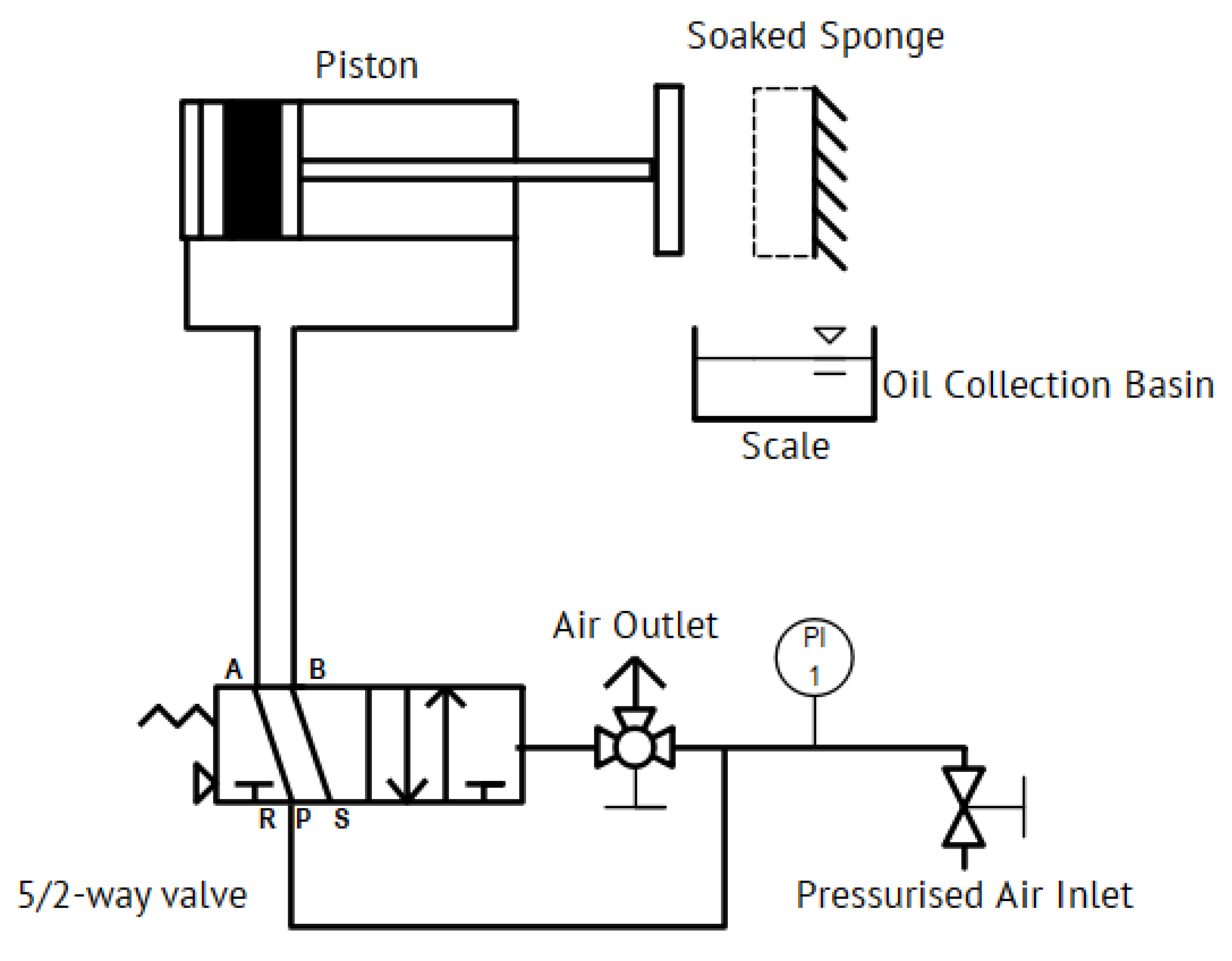
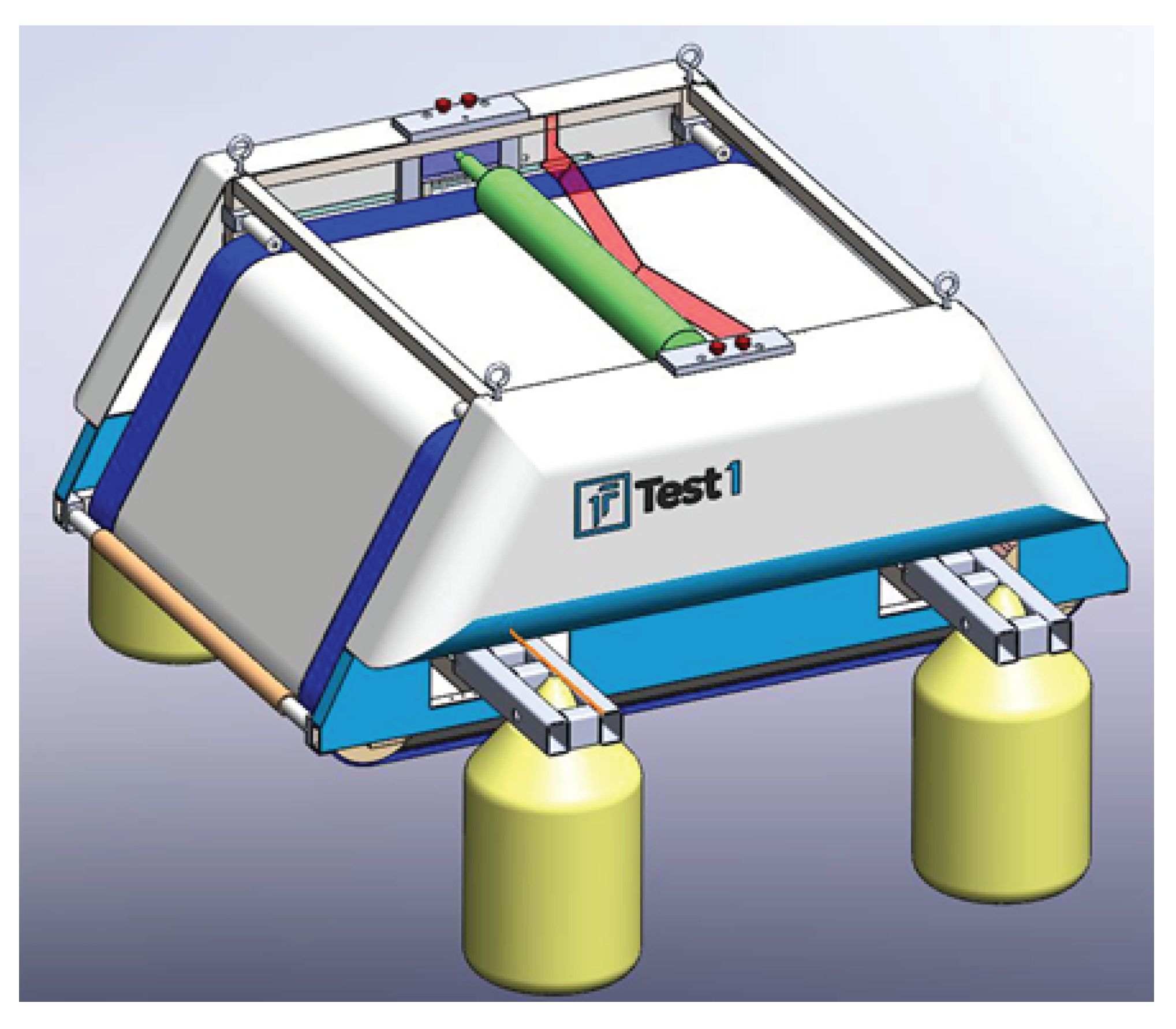
2.3. Experimental Setup

In order to mechanically remove the oil from the RMPUF on the laboratory scale, a pneumatic press with a collection basin is used. The schematic drawing of the press can be found in Figure 2.
The setup consists of two opposing steel plates with a size of 10 × 10 cm, of which one is mounted statically (top right in the drawing) and the other one is moved by a double-acting piston cylinder ( d piston = 40 mm, 50 mm lift, ISO 21287, Riegler, Bad Urach, Germany). The piston is controlled by a pneumatic 5/2-way valve (monostable, 4A310-08, Airtac, Taipei, Taiwan) and a one-way-restrictor. The operating pressure is adjusted by a precision pressure regulator (0.5-8 bar, FUTURA, Riegler, Germany). Prior to squeezing, the sponge is mounted at the static steel plate using two pins in the top corners. Those pins fit through two holes in the opposing moving steel plate. The recovered oil or ASW/oil mixture is collected underneath in a collection basin and weighed with a high-precision balance (M-Power AZ214, Sartorius, Göttingen, Germany). The extending force F ex , which is transmitted from the piston via the rod onto the sponge, is calculated as
F ex = p sys · π 4 d piston 2 ,
with the system pressure p sys and the surface of the piston, which results from the diameter of the piston, ( d piston = 40 mm). The pressure on the sponge, which is referred to as the squeezing pressure p squ , is calculated as
p squ = F ex A sponge
with the sponge’s surface area A sponge of 9.5 × 9.5 cm.

2.4. Measurement Procedure

As a first step, the initial weight of the absorbent m init , sponge is determined before each measurement. Afterwards, an oil pan is filled with 200 g of the oil to be tested (corresponds to a filling height of approximately 10 mm). In the next step, the absorbent is immersed in the test liquid for 30 ± 3 s and subsequently removed to an empty basin for another 30 ± 3 s to let it drain. This procedure ensures that the oil drains from the sponge, which is then taken up via the capillary forces ( m upt , oil ) but cannot be finally recovered from the sponge ( m rec , oil ). As the review paper by Oliveira et al. [19] points out, the complete amount of oil that can usually be absorbed by the absorbent ( m upt , oil ) after a certain dripping time is stated in publications. However, this and many more inconsistencies with other publications are a major problem to compare sorbent performances. The herein-mentioned results display the oil-recovery amount of the absorbent. This is an attempt to determine the recovery capacity that can be achieved in actual practical use ( m rec , oil ).
After the saturation process, the sponge is attached vertically to the two pins at the static steel plate and squeezed at a selected pressure for 30 ± 3 s. The mechanically recovered oil is collected and weighed to gain m rec , oil . In order to enable the comparability of the results, a recovery rate normalised to the initial sponge weight is determined according to Equation (4) as
Normalised recovery rate = m rec , oil m init , sponge .
In the first series of tests, the dependency of the recovery rate on the selected squeezing pressure was determined. For this purpose, the sponge was saturated with white oil as described above and squeezed out at system pressures of 2, 3, 4, and 5 bar. According to Equation (3), this corresponds to squeezing pressures of 27.8, 41.8, 55.7, and 69.7 kN m−2, respectively, acting on the sponge. In the second series of tests, the procedure was repeated for sunflower oil and crude oil; however, this was only completed for squeezing pressures of 27.8 and 55.7 kN m−2 each. All parameters were investigated with three sponge specimens, each consecutively used ten times. Additionally, the reusability of the sponge was investigated via the use of white oil and 50 sorption and desorption cycles. A squeezing pressure of 69.7 kN m−2 was chosen in order to achieve a maximum load on the sponge structure within the desorption process.
In addition to the determination of the exclusive oil recovery rate and the sponge’s reusability, the absorption of seawater also plays a significant role regarding the efficiency of a sponge absorbent in an oil spill clean-up operation. For this purpose, the third series of tests contains repetitive experiments using a mixture of ASW and crude oil to mimic a real-case scenario. The experimental procedure is the same as described above. For this case, a glass basin is filled with artificial seawater of m ASW = 370 g and crude oil. The amount of crude oil was deliberately chosen to be below the allegedly maximum absorption capacity of the sponge at three values of 20, 80, and 130 g. Each experiment is repeated ten times, prewetting the sponge in ASW at the beginning and refilling the basin to the initial oil amount after each absorption and desorption cycle. Each time, the respective ASW/oil mixture, which is mechanically recovered from the sponge, is subsequently filled in a glass separating funnel. After a period of 30 ± 3 s, both the oil and ASW fractions are weighed separately. For the purpose of comparing the sponge’s efficacy at these three different initial crude oil quantities, the actual mass of the recovered oil m rec , oil is related to the initial mass of oil in the basin m init , oil according to Equation (5) as
Normalised oil recovery = m rec , oil m init , oil .
Likewise, the recovery selectivity S oil , rec is determined according to Equation (6) as
S oil , rec ( % ) = m rec , oil m rec , oil + m rec , ASW · 100 .
The herein-described measurement procedure and the experimental setup could be a suitable supplement to the already existing standard test method F726-17 published by ASTM International, in particular the section Reuse with respect to the Compression Extraction (Plate) [21].

3. Experimental Results and Discussion

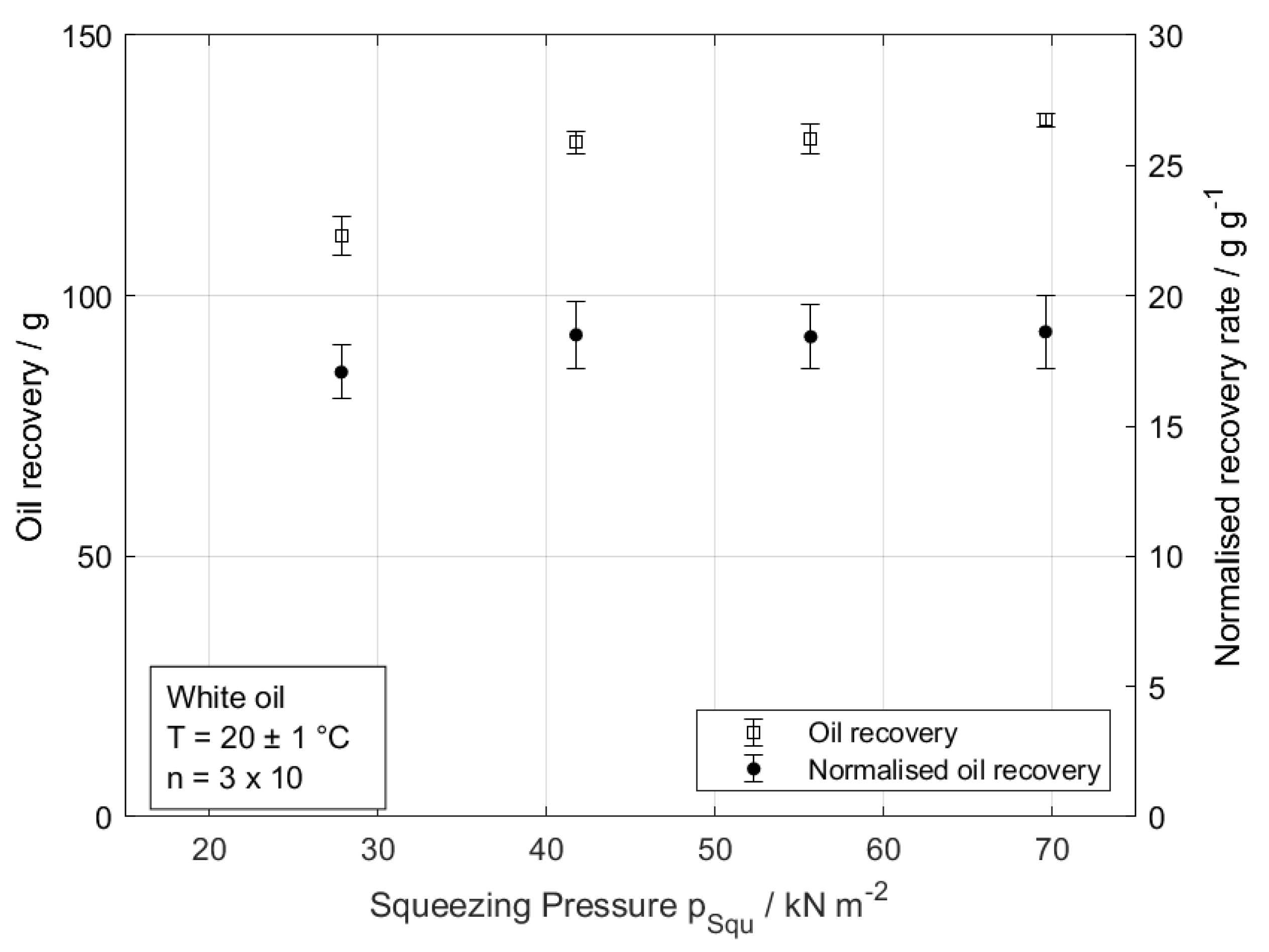
3.1. Oil Recovery with Increasing Squeezing Pressure

An important aspect of using foam as the preferred sorbent material is the effort required to sequentially remove the oil again. In this study, the oil is removed by means of a pneumatic press at different squeezing pressures. In this subsection, only white oil is utilised as a test liquid, due to its chemically harmless properties and the knowledge gained about it in former studies [24]. Figure 3 shows the influence of different squeezing pressures ( p squ ) on the absorption of the soaked sponge. On the left ordinate, the graph shows the total white oil mass that could be recovered. The right ordinate shows the corresponding oil-recovery ratio on a weight basis (g/g). During the tests, three foam cuboids were used per pressure level and squeezed ten times in a row (n = 3 × 10). It can be seen that 111 ± 4 g of oil was recovered at a squeezing pressure of 27.8 kN m−2. This value increases to 129 ± 2 g at 41.8 kN m−2. At higher squeezing pressures, only a minor increase to a total of 134 ± 1 g at 69.7 kN m−2 can be observed. Similar to the trend of recovered oil mass, the trend of the corresponding normalised recovery rate shows a maximum of 18.6 ± 1.4 g of white oil per g of foam at the maximum pressure of 69.7 kN m−2. A change in structure and the associated reduction in absorption capacity cannot be observed at higher pressures and consecutive squeezing processes.

3.2. Recovery Rate of Different Oil Types and Reusability of Foam

In addition to the investigation of the mass of recovered white oil at different squeezing pressures onto the foam, two more oils are used to assess the previous results. The strongly varying surface tension and viscosity have a significant influence on the absorption behaviour. This can be seen in the left two datasets in Figure 4, in which the normalised recovery rates of the foam for white oil, sunflower oil, and crude oil for squeezing pressures of 27.8 kN m−2 and 55.7 kN m−2 are depicted. This bar plot demonstrates the lowest recovery rate for sunflower oil of 9.8 ± 1.3 g/g for 27.8 kN m−2 and 12.5 ± 1.4 for 55.7 kN m−2, respectively. This is significantly less than for white oil and crude oil, which mark a recovery rate of 17.1 ± 1.0 and 13.1 ± 0.9 g/g at 27.8 kN m−2 and a squeezing pressure and 18.4 ± 1.2 and 17.6 ± 0.9 g/g at 55.7 kN m−2 squeezing pressure, respectively. This difference can be attributed to the combination of a comparatively higher surface tension of 32.9 × 10⁻³ N/m and a low viscosity of 5.9 × 10⁻³ Pa s for sunflower oil. In particular, the high surface tension leads to a low wetting of the RMPUF and, thus, to a lower absorption of the sunflower oil compared to the white oil and crude oil [26].
The right-hand dataset of Figure 4 exhibits the normalised recovery rate of the RMPUF for over 50 absorption and desorption cycles with white oil, repeated three times (n = 3 × 50). It can be seen that the recovery rate over 50 cycles has the same value within the standard deviation as the recovery rates after 10 cycles (see Figure 4, left dataset). Therefore, a negative influence on the foam structure and volume due to the selected high squeezing pressure, and, thus, a change in the absorption capacity can be excluded. On the contrary, foam materials such as polyimide or polypropylene (industry standard) failed to recover their initial volume after the first compression cycles [27]. Hence, for the RMPUF in this study, it can be assumed that a distinctively higher number of absorption and desorption cycles is possible without major capacity losses, which has already been demonstrated in a real-case scenario at an actual oil spill clean-up (see Section 4).

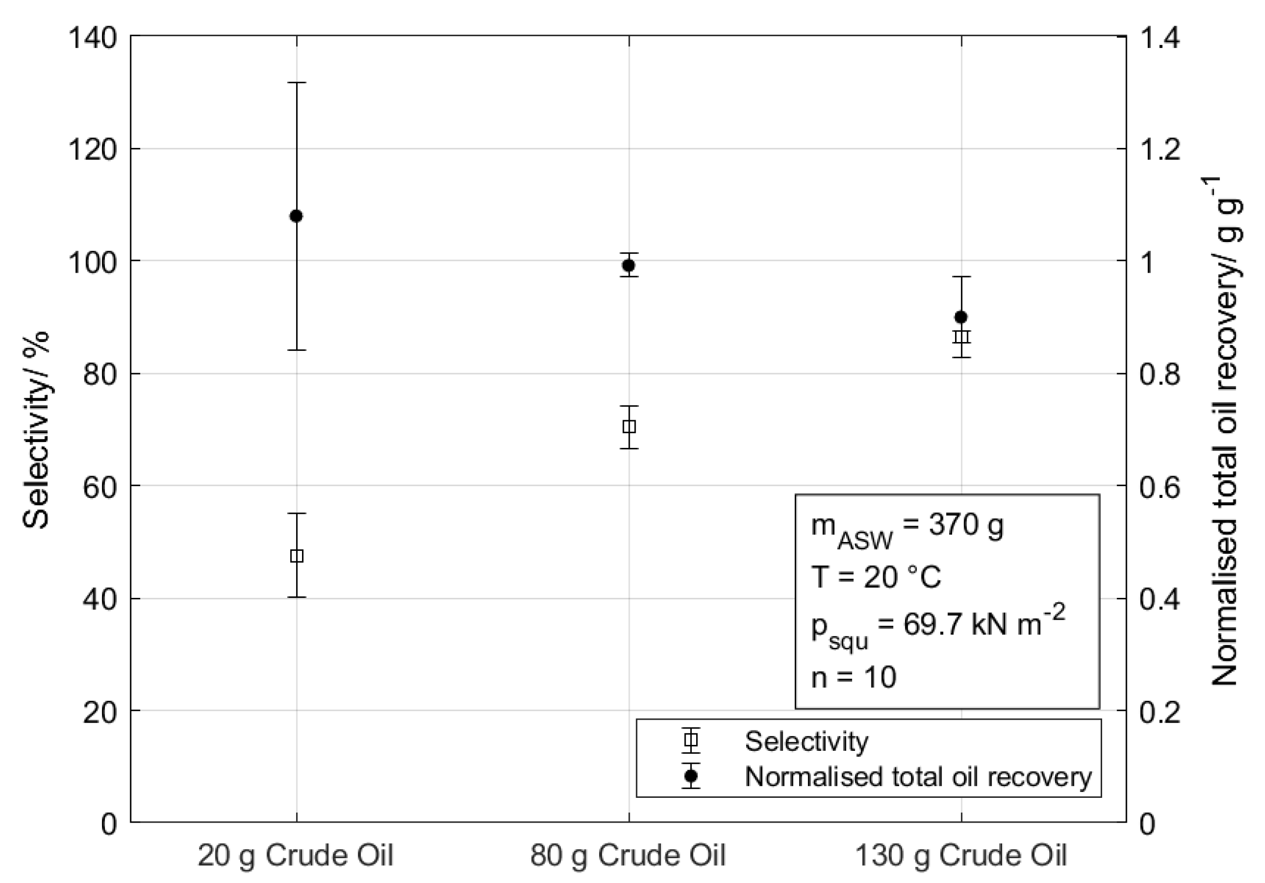
3.3. Investigations with Crude Oil and Artificial Sea Water

Since Barry et al. [27] postulate that oil adsorption and selectivity is dependent on the amount of oil available to the foam, this subsection takes different initial crude oil amounts mixed with Artificial Sea Water (ASW) into consideration and, thus, mimicking a real-case scenario. The tests with ASW are shown in Figure 5, which depicts, on the one hand, the oil sorption selectivity (black circles, left ordinate) and, on the other hand, the normalised total oil recovery (white squares, right ordinate) based on Equations (6) and (5), respectively.
With an increasing amount of initial crude oil in the glass basin, the trend of the selectivity increases from 47.6 ± 7.4 % ( m init , crude oil = 20 g) up to 86.5 ± 1.1% ( m init , crude oil = 130 g). It must be noted that 130 g of crude oil is chosen as a maximum amount due to the results demonstrated in Figure 3 at a squeezing pressure of 69.7 kN m−2. Interestingly, despite the material’s hydrophobic property, in repetitive trials, certain water uptake is observed. However, all initially presented oil is recovered. This becomes apparent by observing the second dataset in the graph on the right ordinate. The normalised total oil recovery (mass of recovered oil/mass of initially presented crude oil) shows how much of the initial oil inside the basin could be recovered. All three values are between 1.1 and 0.9 g/g with standard deviations between 0.24 and 0.07 g/g, respectively. The reason for the value higher than 1.0 and the high standard deviation is due to the used separator funnel. During the separation process and weighing, part of the oil remains on the walls of the separator due to the high viscosity of the oil. This leads to a non-negligible error in the weighing, especially when using small quantities of oil. To sum up, all three values show a very good oil recovery, which clearly demonstrates the high efficacy of the foam. The results also show that the crude oil is able to displace absorbed water from the sponge structure due to its oleophilic and hydrophobic (see Figure 1d) properties.
As mentioned above, a direct comparison of the herein-demonstrated results with other studies is difficult for several reasons, such as an unclear absorption method [22,28], a water-column absorption testing method [27], or repeated sorption/compression/ re-sorption tests not being standardised [29] regarding the reusability. However, considering that the latter publication took the ASTM F726-17 standard into account, the herein-presented material may be further improved by a sequential infiltration synthesis-based modification.

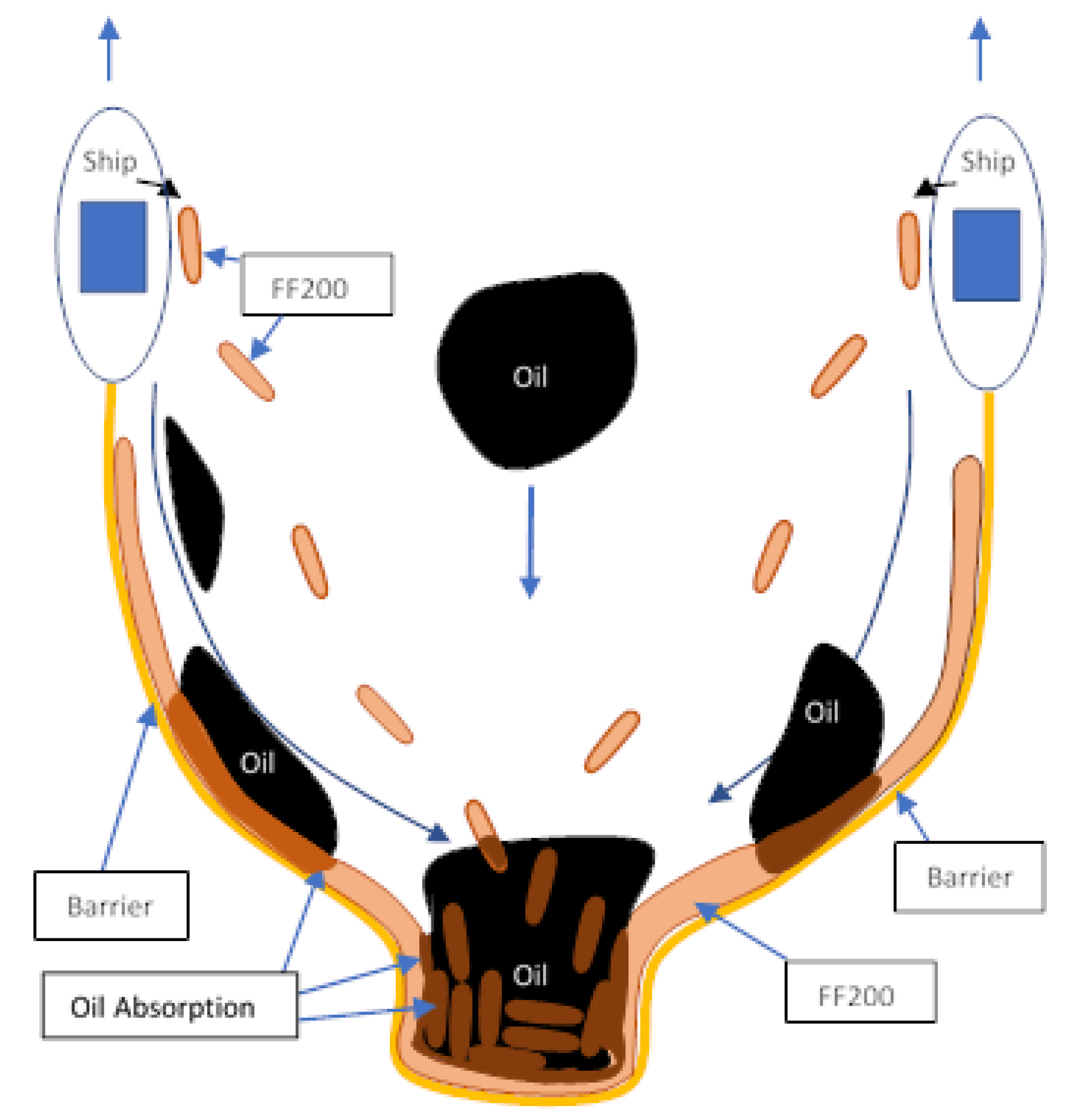
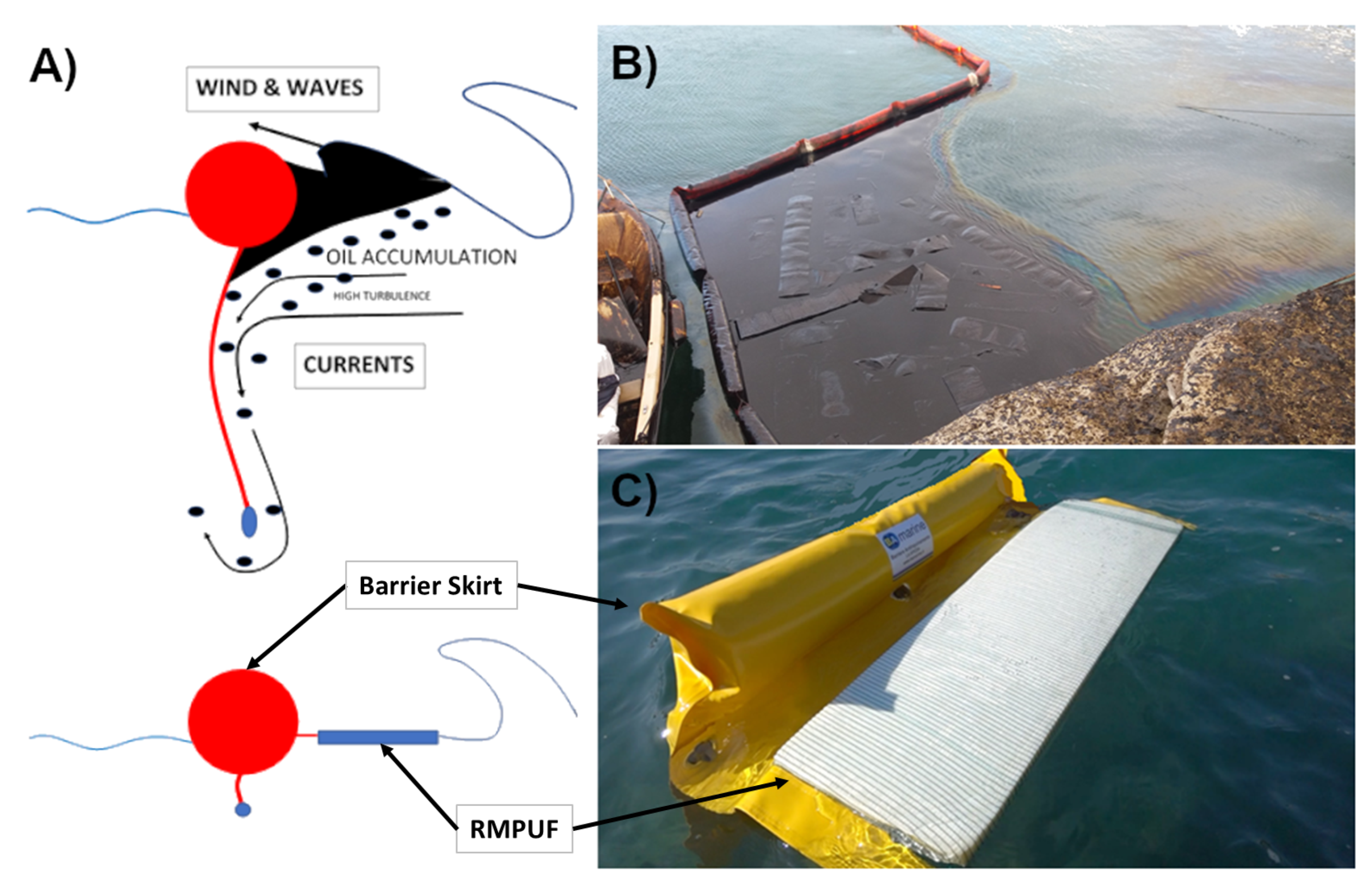
4. Field Experience with the RMPUF in Real Oil Spill Response Conditions

The removal of hydrocarbons from seawater in the field is fundamentally different from laboratory conditions. For example, wind, swell, and ocean currents make it difficult to remove oil from the water surface and cause hydrocarbons to spread widely over the surface and wash up on coasts. Thus, in the DWH accident, it was not possible to contain the oil spill locally. As a result, coasts in Cuba, Mexico, and five states in the United States were polluted by the spilled oil [30]. The accumulation of debris and waste in oil spills plays a significant role in the recovery process and can significantly reduce the effectiveness of already established technologies such as skimmers, barriers, booms, and pumps. Under these conditions, the use of sponge-structured absorbers is advantageous, as they can absorb oil even under difficult conditions until the maximum capacity of the absorber is reached. In the case of the RMPUF presented here, oil is only released when a stronger force is applied. The sponge is able to bind the oil safely over a longer period of time.

4.1. Field Trial in Gran Tarjal (Fuerteventura, Spain)

During a three-day field trial in 2018, hydrocarbons were removed from the port of Gran Tarjal on the coast of Fuerteventura. Tropical storm Emma caused five pontoons with machinery and three tugboats to sink in the harbour basin, resulting in heavy contamination of the harbour area by marine diesel, hydraulic oil, and fuel oil. During this field test, the oil-absorption capacity of the RMPUF was compared with the oil-recovery potential of a SK10R skimmer (Inteco Astur, Carreno, Spain). In this trial, 20 kg of RMPUF was applied by an inexperienced team of ten people, and the absorbed oil was removed mechanically using two manual wringers. The advantages of the skimmer used were clearly demonstrated. The sponge was able to remove 57 tonnes of hydrocarbons from the harbour basin over the three-day period. The oil removed had a water content of about 5% v/v, which allows direct reuse in a refining process and eliminates the need for further treatment steps. The skimmer was able to remove a 500 kg water/oil mixture from the harbour basin within the three-day period. Due to the high water content of the removed oil/water mixture of 50% v/v, further processing steps were necessary for disposal.

4.2. Barriers

As already mentioned, in addition to rapid removal, the containment of oil spills is also an essential aspect of protecting the maritime environment. Oil barriers are classically used for this purpose. If the oil hits the barriers vertically in combination with waves and wind, the oil can be washed over the barriers. Likewise, the oil can be washed under the barriers by the currents (see Figure 6). In order to suppress this as far as possible, the dimensions of the submerged barrier skirts can be increased up to a height of approximately 1 m. This makes the handling of the barriers more difficult due to the increased drag and leads to a significant increase in costs when used on the open sea.
A combination of a sponge-structured absorber and a barrier could reduce these disadvantages. The absorber reduces the turbulence caused by the waves and binds the oil in the absorber, thus making it difficult to overflow or underflow the barrier (see Figure 6). The higher efficiency also reduces the size of the skirts and improves the handling. Due to the improved handling, faster response times for oil spill events can be realised.
One method to tackle an oil spill is shown in Figure 7. Here, the synergies of the modified barrier and the RMPUF can be ideally used. For this purpose, the modified barrier is deployed and towed by two vessels. The oil film is pulled into the center of the barrier, in which there is a concave bulge collecting the unabsorbed oil. If necessary, more RMPUF can be applied by the deployed tug boats to bind further oil. The sponges can then be removed by hand by means of a net or by an already designed sophisticated marine surface robotic system. Its use as a static barrier as preventive protection is also conceivable, since, as shown in the experiments, hydrocarbons are able to displace seawater and permanently bind to the absorber. These properties could also be of interest in other future applications, such as using the sponges to treat oily bilge water. This is one of the primary sources of oil pollution in marine waters. Moreover, an improved skimmer design based on the sponge could be realised that achieves a higher oil selectivity than existing skimmers. The design of a corresponding prototype is shown in Figure 8. The prototype moves an endless belt of sponge that is squeezed and exposed to the surface of water at each turn. The information obtained within the laboratory tests, e.g., about the squeezing pressure, is used to identify an optimal operating point for such a concept of skimmer.

5. Conclusions

Within the scope of this paper, a reusable and modified polyurethane sponge for the absorption of oils was characterised. For this purpose, a pneumatic press was built to investigate the mechanical removal of the absorbed oil from the sponge in more detail. It could be shown that the sponge achieves a normalised recovery rate of 18 g/g maximum. The recovery rate was investigated as a function of three different oils, and it could be shown that the absorption of the sponge strongly depends on the oil applied and, in particular, its surface tension and viscosity.
Another research focus was on the reusability of the sponge. Thereby, the dependency of the recovery rate on the squeezing pressure of the press was examined. It was also shown that, after 50 cycles of sorption and desorption, there is no significant decrease in the recovery rate and no material deformation.
In addition, laboratory tests were carried out with different crude oil mass fractions in ASW. The oil quantities were selected in such a way that they were below the maximum absorption capacity of the sponge. In all cases, more than 90% of the oil could be absorbed. It could be shown that, with an increasing oil quantity, the water is displaced from the sponge, thus increasing the selectivity of the oil in the desorption.
What the use of such an absorbent looks like under real conditions and which challenges arise in the practical use. It is important to clarify how a sponge-shaped absorbent can be optimally adapted to real conditions. For example, what influence does swell have on the absorption behaviour? How must an absorber be structurally designed in order to be optimally used in the open sea or in calm harbour waters? What is the behaviour of an absorber sponge under arctic conditions and the associated higher viscosity and surface tension of crude oils? Another interesting application is the use of absorbers below the surface of the sea, e.g., directly at crude oil spills.

Author Contributions

Conceptualization, D.N. and S.H.; methodology, D.N., S.H. and J.C.-A.; validation, D.N. and S.H.; formal analysis, D.N. and S.H.; investigation, S.B.K. and J.C.-A.; resources, M.H. and J.C.-A.; writing–original draft preparation, D.N., S.H. and J.C.-A.; writing–review and editing, D.N., S.H., M.H., J.C.-A. and M.S.; visualization, D.N., S.H. and J.C.-A.; supervision, M.S. and J.C.-A.; project administration, D.N. and S.H.; funding acquisition, M.H. All authors have read and agreed to the published version of the manuscript.

Funding

This research received no external funding.

Data Availability Statement

Please contact Marko Hoffmann ([email protected]) to obtain access to the data.

Acknowledgments

The publishing fees were funded by the Deutsche Forschungsgemeinschaft (DFG, German Research Foundation)—project number 491268466—and the Hamburg University of Technology (TUHH) in the funding program “Open Access Publishing”. The authors gratefully acknowledge the provision of foam material by the company Test1 Solutions (Brescia, Italy). Furthermore, we thank Martin Ritter from the electron microscopy unit at the Hamburg University of Technology for his support and the provision of the SEM images, as well as Sina Bertram for the great support with the laboratory trials.

Conflicts of Interest

The authors declare no conflict of interest.

Abbreviations

The following abbreviations are used in this manuscript:
ASTMAmerican Society for Testing and Materials
ASWArtificial Seawater
DWHDeepwater Horizon
HFWHorizontal Field Width
ITOPFInternational Tanker Owners’ Pollution Federation
RMPUFReusable Modified Polyurethane Foam

References

  1. Focus of Energy Transition Council (ETC). 2021. Available online: https://ukcop26.org/focus-of-energy-transition-council-etc/ (accessed on 16 November 2021).
  2. Muehlenbachs, L.; Cohen, M.A.; Gerarden, T. The Impact of Water Depth on Safety and Environmental Performance in Offshore Oil and Gas Production. Energy Policy 2013, 55, 699–705. [Google Scholar] [CrossRef]
  3. Eklund, R.L.; Knapp, L.C.; Sandifer, P.A.; Colwell, R.C. Oil Spills and Human Health: Contributions of the Gulf of Mexico Research Initiative. GeoHealth 2019, 3, 391–406. [Google Scholar] [CrossRef]
  4. McNutt, M.K.; Camilli, R.; Crone, T.J.; Guthrie, G.D.; Hsieh, P.A.; Ryerson, T.B.; Savas, O.; Shaffer, F. Review of Flow Rate Estimates of the Deepwater Horizon Oil Spill. Proc. Natl. Acad. Sci. USA 2012, 109, 20260–20267. [Google Scholar] [CrossRef] [PubMed]
  5. Tao, Z.; Bullard, S.; Arias, C. High Numbers of Vibrio Vulnificus in Tar Balls Collected from Oiled Areas of the North-Central Gulf of Mexico Following the 2010 BP Deepwater Horizon Oil Spill. EcoHealth 2011, 8, 507–511. [Google Scholar] [CrossRef] [PubMed]
  6. US Coast Guard. On Scene Coordinator Report Deep Water Horizon Oil Spill; Technical Report; United States Coast Guard: Washington, DC, USA, 2011. [Google Scholar]
  7. Beyer, J.; Trannum, H.C.; Bakke, T.; Hodson, P.V.; Collier, T.K. Environmental Effects of the Deepwater Horizon Oil Spill: A Review. Mar. Pollut. Bull. 2016, 110, 28–51. [Google Scholar] [CrossRef] [PubMed]
  8. Sackeyfio, N. Oil Tanker Spill Statistics 2020; Technical Report; International Tanker Owners Pollution Federation (ITOPF Ltd.): London, UK, 2021. [Google Scholar]
  9. Chow, D. How We Clean Oil Spills Hasn’t Changed in Decades. These Scientists Want to Change That. NBC News, 7 October 2021. [Google Scholar]
  10. Douglas, D.; Stelloh, T. Oil Spill off California Coast Closes Pipeline, Prompts Warnings of Ecological Disaster. NBC News, 3 October 2021. [Google Scholar]
  11. Brussaard, C.; Peperzak, L.; Beggah, S.; Wick, L.; Wuerz, B.; Weber, J.; Samuel Arey, J.; Van Der Burg, B.; Jonas, A.; Huisman, J.; et al. Immediate Ecotoxicological Effects of Short-Lived Oil Spills on Marine Biota. Nat. Commun. 2016, 7. [Google Scholar] [CrossRef] [PubMed]
  12. Ivshina, I.B.; Kuyukina, M.S.; Krivoruchko, A.V.; Elkin, A.A.; Makarov, S.O.; Cunningham, C.J.; Peshkur, T.A.; Atlas, R.M.; Philp, J.C. Oil Spill Problems and Sustainable Response Strategies through New Technologies. Environ. Sci. Process. Impacts 2015, 17, 1201–1219. [Google Scholar] [CrossRef] [PubMed]
  13. ITOPF. Technical Information Paper 03: Use of Booms in Oil Pollution Response; Technical Information Paper 03; ITOPF: London, UK, 2011. [Google Scholar]
  14. International Tanker Owners Pollution Federation (ITOPF Ltd.). Technical Information Paper 08: Use of Sorbent Materials in Oil Spill Response; Technical Information Paper 08; ITOPF: London, UK, 2012. [Google Scholar]
  15. Dhaka, A.; Chattopadhyay, P. A Review on Physical Remediation Techniques for Treatment of Marine Oil Spills. J. Environ. Manag. 2021, 288, 112428. [Google Scholar] [CrossRef] [PubMed]
  16. Al-Jammal, N.; Juzsakova, T. Review on the Effectiveness of Adsorbent Materials in Oil Spills Clean Up. Desalination 2016, 8. Available online: https://www.researchgate.net/publication/319254182_Review_on_the_Effectiveness_of_Adsorbent_Materials_in_Oil_Spills_Clean_Up (accessed on 1 January 2020).
  17. Hadji, E.M.; Fu, B.; Abebe, A.; Bilal, H.M.; Wang, J. Sponge-Based Materials for Oil Spill Cleanups: A Review. Front. Chem. Sci. Eng. 2020, 14, 749–762. [Google Scholar] [CrossRef]
  18. Kukkar, D.; Rani, A.; Kumar, V.; Younis, S.A.; Zhang, M.; Lee, S.S.; Tsang, D.C.; Kim, K.H. Recent Advances in Carbon Nanotube Sponge–Based Sorption Technologies for Mitigation of Marine Oil Spills. J. Coll. Interface Sci. 2020, 570, 411–422. [Google Scholar] [CrossRef] [PubMed]
  19. Oliveira, L.M.; Saleem, J.; Bazargan, A.; Duarte, J.L.d.S.; McKay, G.; Meili, L. Sorption as a Rapidly Response for Oil Spill Accidents: A Material and Mechanistic Approach. J. Hazard. Mater. 2021, 407, 124842. [Google Scholar] [CrossRef] [PubMed]
  20. Zamparas, M.; Tzivras, D.; Dracopoulos, V.; Ioannides, T. Application of Sorbents for Oil Spill Cleanup Focusing on Natural-Based Modified Materials: A Review. Molecules 2020, 25, 4522. [Google Scholar] [CrossRef] [PubMed]
  21. ASTM International. Standard Test Method for Sorbent Performance of Adsorbents for Use on Crude Oil and Related Spills; Test Method F726-17; ASTM International: West Conshohocken, PA, USA, 2017. [Google Scholar]
  22. Peng, L.; Yuan, S.; Yan, G.; Yu, P.; Luo, Y. Hydrophobic Sponge for Spilled Oil Absorption. J. Appl. Polym. Sci. 2014, 131. [Google Scholar] [CrossRef]
  23. Pesch, S.; Schulz, S.; Aboud, N.; Schlüter, M. Experimental Investigation of Pure and Gas-Saturated Crude Oil Viscosity and Density from 268 to 308 K and Up to 23 MPa. J. Chem. Eng. Data 2021, 66, 2355–2365. [Google Scholar] [CrossRef]
  24. Pesch, S.; Knopf, R.; Radmehr, A.; Paris, C.B.; Aman, Z.M.; Hoffmann, M.; Schlüter, M. Experimental Investigation, Scale-Up, and Modeling of Droplet Size Distributions in Turbulent Multiphase Jets. Multiph. Sci. Technol. 2020, 32, 113–136. [Google Scholar] [CrossRef]
  25. Jones, R.F.; Speer, H.L.; Kury, W. Studies on the Growth of the Red Alga Porphyridium Cruentum. Physiol. Plant. 1963, 16, 636–643. [Google Scholar] [CrossRef]
  26. Nguyen, P.Q.P.; Hoang, A.; Al Tawaha, A.R. A Study of Oil Absorbing Capacity of Cellulose-implemented Polyurethane for the Recovery of Oil Spills. Int. J. e-Navig. Marit. Econ. 2018, 9, 25–34. [Google Scholar]
  27. Barry, E.; Libera, J.A.; Mane, A.U.; Avila, J.R.; DeVitis, D.; Van Dyke, K.; Elam, J.W.; Darling, S.B. Mitigating Oil Spills in the Water Column. Environ. Sci. Water Res. Technol. 2018, 4, 40–47. [Google Scholar] [CrossRef]
  28. Zhou, X.; Zhang, Z.; Xu, X.; Men, X.; Zhu, X. Facile Fabrication of Superhydrophobic Sponge with Selective Absorption and Collection of Oil from Water. Ind. Eng. Chem. Res. 2013, 52, 9411–9416. [Google Scholar] [CrossRef]
  29. Barry, E.; Mane, A.U.; Libera, J.A.; Elam, J.W.; Darling, S.B. Advanced Oil Sorbents Using Sequential Infiltration Synthesis. J. Mater. Chem. A 2017, 5, 2929–2935. [Google Scholar] [CrossRef]
  30. Wilson, M.; Bailey, D.; Maung-Douglass, E.; Partyka, M.; Skelton, T.; Swann, L. Deepwater Horizon: Where Did It Go? GOMSG-G-21-013. 2021. Available online: https://masgc.org/ (accessed on 1 January 2020).
Figure 1. Scanning electron microscope images of the RMPUF at different magnifications and horizontal field widths (HFW) as (a) HFW = 2075 µm, (b) HFW = 276 µm, and (c) HFW = 13 µm. Dimensional scaling is marked in the respective images. (d) Optical measurement of the wetting angle θ ( 95 ± 3 ) between ASW and the RMPUF.
Jmse 10 01369 g001
Figure 2. Scheme of the experimental setup for mechanical removal of oil from the sponge. A 5/2-way valve and a one-way restrictor are used to fill and empty the pressure chambers of the double-acting piston cylinder with pressurised air from the air inlet.
Jmse 10 01369 g002
Figure 3. Total amount of recovered white oil (white squares, left ordinate) and normalised recovery rate (black circles, right ordinate) as a function of squeezing pressure.
Jmse 10 01369 g003
Figure 4. Left two datasets: Normalised recovery rate for all three used oil types as a function of squeezing pressure p squ of 27.8 and 55.7 kN m−2 (n = 3 × 10 consecutive repetitions). Right dataset: Normalised recovery rate only for white oil at a squeezing pressure of 69.7 kN m−2 (n = 3 × 50 consecutive repetitions).
Jmse 10 01369 g004
Figure 5. Oil recovery selectivity (white squares, left ordinate) according to Equation (6) and normalised total oil recovery (black circles, right ordinate) according to Equation (5) with respective standard deviations (n = 10) as a function of initially presented crude oil quantities in a basin of 370 g ASW.
Jmse 10 01369 g005
Figure 6. (A) Comparison between the standard design of a barrier and the new design of a barrier with the sponge attached. (B) A combined disposition of barriers and RMPUF to concentrate the oil. (C) New design of a barrier with the RMPUF attached with a simpler system to change the foam.
Jmse 10 01369 g006
Figure 7. Schematic design of an example of combination between standard barrier and RMPUF, operating in open sea.
Jmse 10 01369 g007
Figure 8. Preliminary design of one skimmer based on RMPUF characteristics.
Jmse 10 01369 g008
Table 1. Dynamic viscosity and surface tension of the sunflower oil, white oil, and crude oil at 20.0 ± 1.0 °C.
Oil TypeDynamic Viscosity η /Pa·sSurface Tension σ /N·m−1
Sunflower Oil5.9 × 10−332.9 × 10⁻³
White Oil4.8 × 10−321.1 × 10⁻³
Crude Oil38.8 × 10−326.2 × 10⁻³
Table 2. Composition of the ASW.
ComponentConcentration c/g·L−1
NaCl27.0
MgSO4·7H2O6.6
MgCl2·6H2O5.6
CaCl2·2H2O1.5
KNO31.0
Publisher’s Note: MDPI stays neutral with regard to jurisdictional claims in published maps and institutional affiliations.

