1. Introduction
Maritime transport is one of the essential means of transportation of goods and cargo. It encourages globalisation with more than 80% of various cargo transported by sea [
1]. The sustainability of sea transport is vital. In cases of oil pollution, the need is to react quickly and correctly to maintain unhindered transport and to protect human health and the environment. Transportation of oil opens risks and possibilities of significant pollution of the sea and the nearby coast [
2,
3]. Throughout history, liquid cargo ships have significantly affected the environment by spilling large amounts of oil into the sea. One of the major tanker accidents was the discharge of oil from the ship Torrey Canyon in 1967. Over 300 km of the English and French coasts were polluted. As a consequence, nearly 15,000 seabirds have died [
4,
5]. Furthermore, maritime accidents such as Exxon Valdez in 1989 have resulted in the adoption of preventive measures. After the accident, it was proposed that a double hull should be placed on liquid cargo ships instead of a single hull. This preventive measure has significantly affected the reduction in oil discharges in cases of maritime accidents of liquid cargo ships [
6].
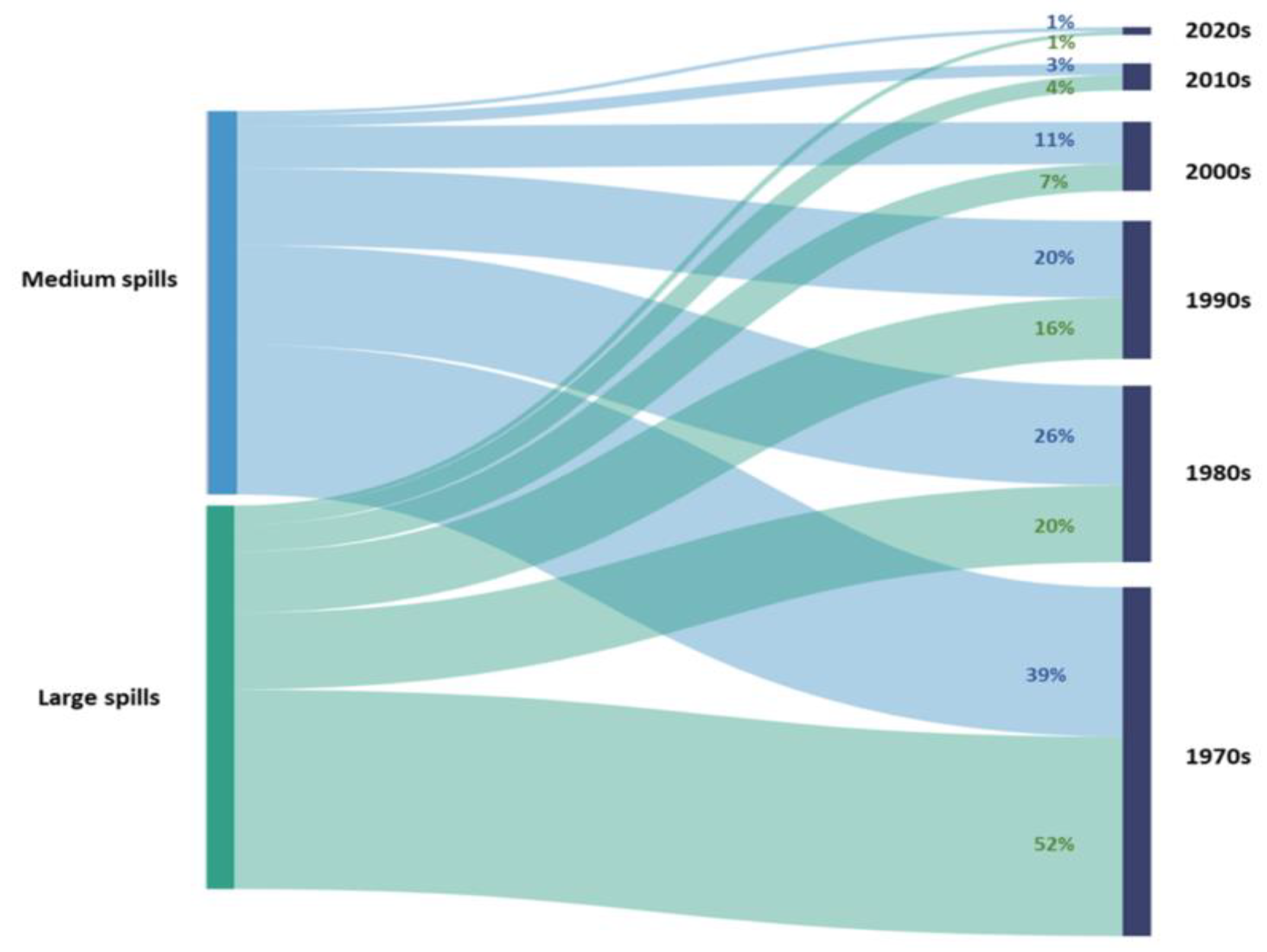
Figure 1 shows the amount of oil spilt from the tanker measured in tons. Medium spills are 7 to 700 tons, while large spills are over 700 tons. It is also evident that more than half (52%) of large-scale pollution occurred in the 1970s.
Furthermore,
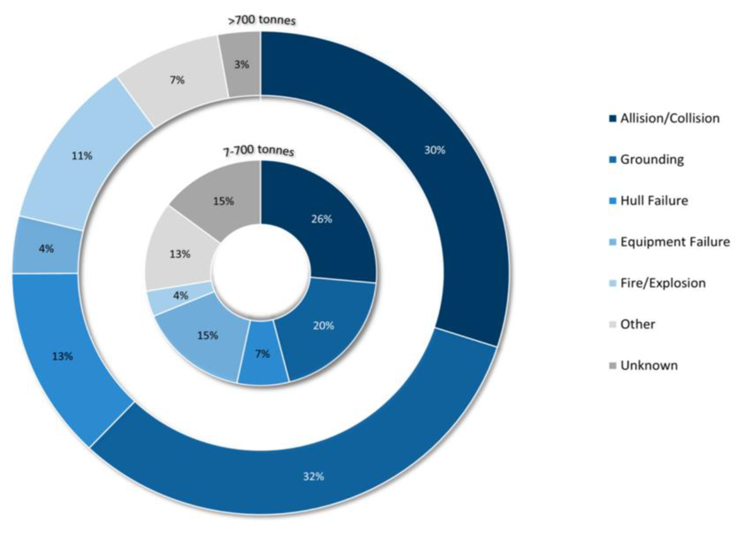
Figure 2 shows oil spills that are in the range of 7–700 tons and over 700 tons in the period from 1970 to 2021. It can be seen that in both cases, collision was one of the main reasons for the oil spill on the sea surface.
Different types of equipment for removing marine and coastal oil pollution are available today. There is a need for optimal solutions for selecting the equipment for the removal of various pollutants. It is the selection of appropriate equipment that can significantly reduce damage to the environment and accelerate the response to oil pollution. This research aimed to use a quantitative research method, i.e., systematic empirical research of observable phenomena of the behaviour of various mechanical equipment such as skimmer devices, to investigate in which weather conditions and for which type of persistent oil a skimmer has the best efficiency, together with the best characterisation of selectivity. The authors did not conduct testing of pumps and skimmers in real conditions with oils. The research objectives were to obtain statistical results able to determine the advantages and disadvantages of the individual skimmers and their usability in various situations of marine oil pollution. It also follows the need to classify the equipment and to correctly address the appropriate equipment for individual contaminants. Previous research has shown a lack of consideration of the importance of pump capacity in relation to the skimmer device. In this paper, the shortcomings of previous research were supplemented, and the importance of the relationship between pumps and skimmers in marine pollution is presented. The suggested model may shorten the time of collecting oil from the sea surface.
The following section presents research related to the use of skimmers in oil pollution and the importance of oil weathering processes. The importance of other specialised equipment, such as booms, is discussed further. The use of different skimmers with appropriate pumps is presented, followed by the study results. The latter showed significant differences in using various skimmers for accidental marine pollution responses. The importance of choosing the proper pump was emphasised, referring to each particular skimmer for the optimal collection rate of marine oil removal. Together with main findings, suggestions for the use of skimmers and pumps are proposed in the concluding chapter to reduce the response time to accidental marine pollution.
2. Previous Research
Kosheleva et al. (2022) [
8] emphasised the importance of maintenance of skimmers. However, the authors did not consider the importance of pumps and other equipment that significantly raises the functionality. Efe et al. (2022) [
9] explained the importance of skimmers in removing oil from the sea surface, considering skimmer discs solely and not the pumps’ capacities. Additionally, the authors only analysed skimmers on vessels for accidental marine pollution response. It is important to differentiate oleophilic skimmers, weir skimmers, and mechanical skimmers. Regardless of the type, each must be set up in a way to collect as much oil and as little seawater as possible. The skimmer device can be a stand-alone device immersed in the sea or installed on a ship [
10]. Knowing the advantages and disadvantages of skimmers is one of the critical factors for the proper response to marine pollution. Disc and weir skimmers are shown in
Figure 3.
Zafirakou et al. (2018) [
12] analysed the state-of-the-art related to the complexity of equipment such as pumps, power packs, and tanks for storage of collected oil. In their work, the authors did not consider the selectivity and impact of pump capacity on the skimmer. Furthermore, the type of skimmer device selection depends on the weather conditions. During larger waves, certain skimmers collect much more seawater.
Methods such as in situ burning or using dispersants can give good results in terms of reducing the amount of collected oil. However, such methods can be very toxic. The biggest disadvantage of the in situ burning methods is that there is a transfer of pollution. Tiny particles of smoke and ash mix with the air or settle on the seabed, leading to new pollution. Additionally, the in situ method must be applied in the first few hours because of the evaporation and because it is much harder to burn oil at a later stage. For the dispersants to be effective, the sea must be wavy enough so that it can disperse the oil. Furthermore, legal regulations for the use of dispersants must be followed. For these reasons, the skimmer device is one of the safest and most widely used method for removing marine pollution [
12,
13].
Ghannam et al. (2022) [
13] emphasised the importance of the oil’s viscosity. High-viscosity oils such as crude oil are used as a propellant for ships. These oils are extraordinarily thick and challenging for removal. If the ambient temperature is below the flow point, the oil becomes semi-solid and therefore difficult to recover due to the aggravated flow towards the skimmer. The authors pointed to the possibility of the formation of an oil emulsion, which may affect the efficiency of the skimmer.
Dhaka et al. (2021) [
14] introduced various techniques for removing pollution from the sea surface. The authors reviewed physical remediation techniques for treating marine oil spills and emphasised the importance of proper use of the equipment. The authors did not consider different skimmers such as disc, brush, and weir skimmers.
A further challenge in selecting specialised marine pollution response equipment is estimating the amount of the spill. In some cases, the estimated amount of spilled oil is relatively clear, such as when a tanker loses all or part of its cargo. Additionally, the amount of spillage from the pipeline can often be determined quite accurately by the pumping speeds and timing of spillage. In the case of continuous discharge over time, as it was the case in the loss of control of the Deepwater Horizon, determining the discharge rate may be more difficult. Another challenge is to estimate the amount of oil collected from the sea surface [
15,
16].
In [
17,
18], the persistent oil was added to a tank, the oil thickness being 3–6 mm. The study aimed to calculate the oil recovery rate (
) and oil recovery efficiency (
) for an individual disc skimmer:
where
= volume of split oil and
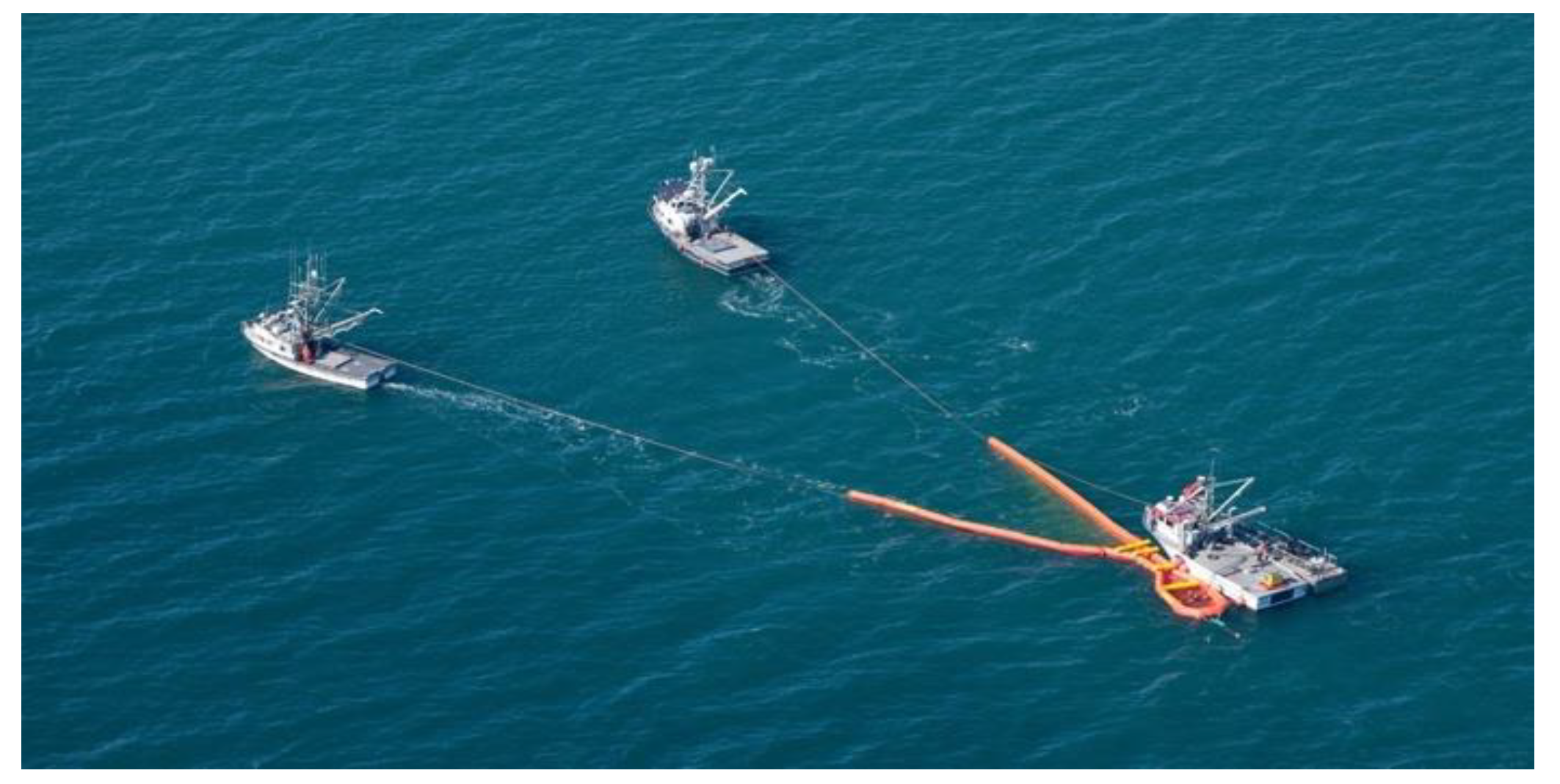
= collected oil along with seawater. The main reservoir was covered to reduce the amount of oil loss due to the vaporisation process and to prevent any contaminants such as dust, debris, insects, etc. from falling inside the reservoir. The present investigation was conducted at a temperature of approximately 25 °C. It is essential to point out that above research was conducted on land. For similar analyses at sea, localising the oil in one place with the booms is necessary. An example of collecting oil using a skimmer is shown in
Figure 4.
Proper use of the skimmer device is crucial for the quick and efficient collection of oil. To use the skimmer properly, certain conditions have to be met. The oil or other particles which have to be collected must be localised, the exact speed of the skimmer must be selected, the exact type of skimmer must be selected for each type of oil spilled, and logistical knowledge is required. The terms ‘logistical knowledge’ and ‘quick response’ imply the following [
20]:
- (a)
Transport of specialised equipment to the pollution site;
- (b)
Installation of equipment at the site;
- (c)
Workforce organisation;
- (d)
Organisation of maintenance and storage of equipment after use;
- (e)
Removal and collection of unplanned waste.
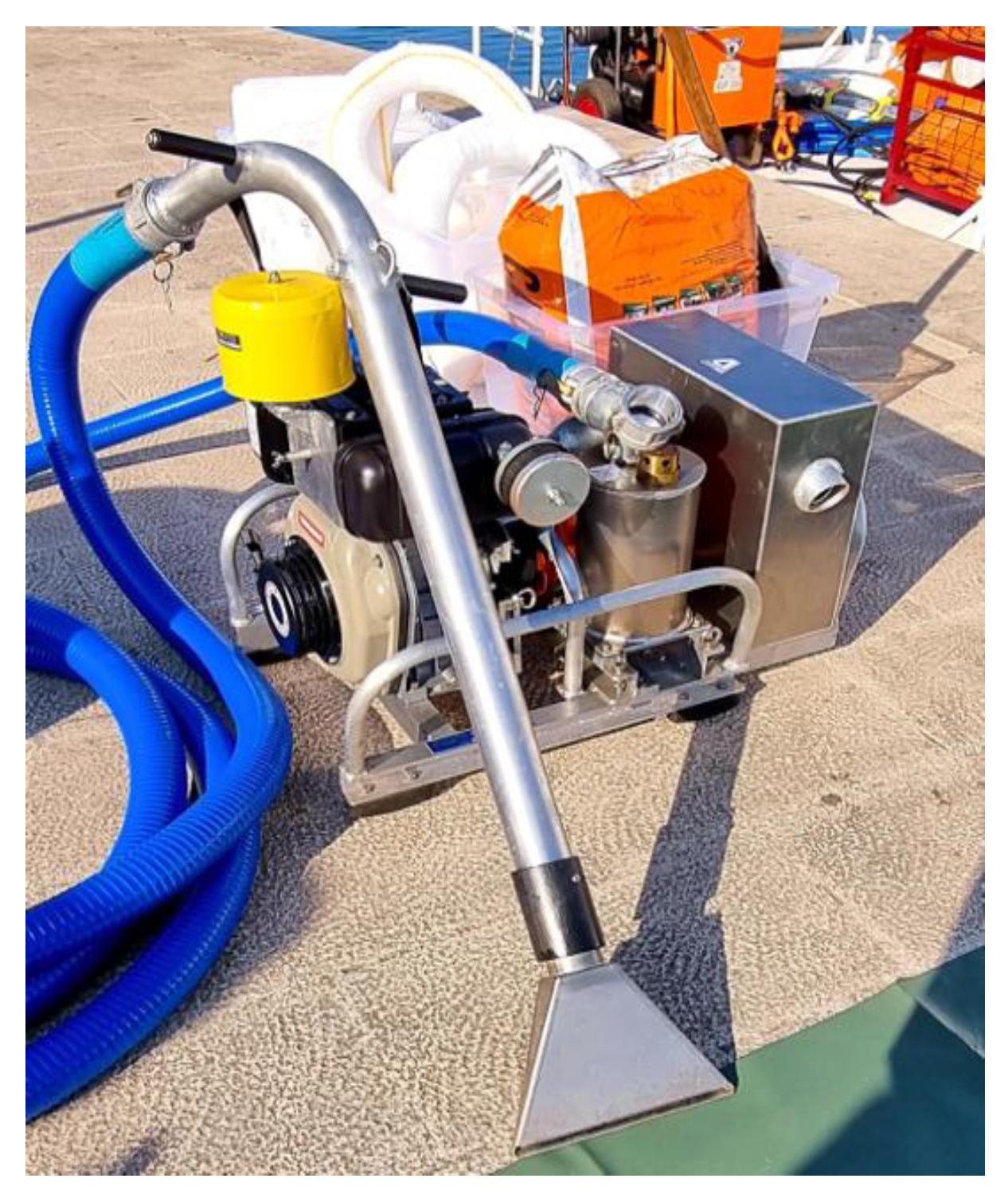
A vacuum skimmer for non-persistent oils is shown in
Figure 5.
Using a skimmer device is one of the most common choices when responding to accidental marine pollution. Unlike other cleaning techniques, the mechanical method can be effectively applied to the treatment of emulsified oils and oils of variable viscosity. It can be time-consuming and expensive when it is used on a large scale, and it requires a large number of staff and equipment. Moreover, cleaning costs rapidly increase with each additional cleaning hour [
20,
21].
3. Different Efficiencies of Individual Types of Skimmers with Appropriate Pumps
The skimmer device can be built-in on a response ship or it can act as a stand-alone device. In order for any type of skimmer device to effectively collect oil from the surface, additional equipment is needed [
22]. Various combinations of skimmers with different pumps were analysed. Each skimmer device collects oil at different speeds, and the collection speed significantly depends on the type of pump connected to each skimmer [
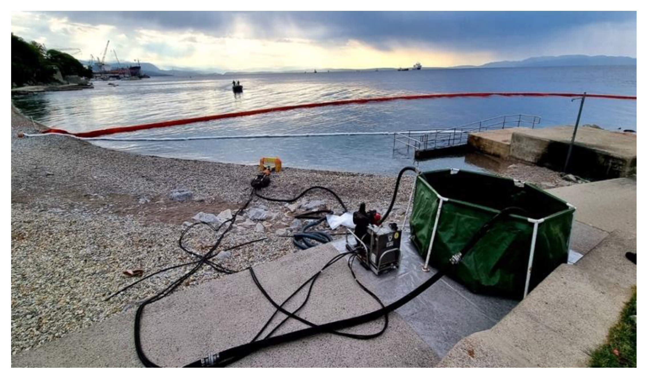
23]. In this paper, 13 different skimmer devices with 11 different pumps were analysed. The disc skimmer device at the contamination site is presented in
Figure 6. The boom is needed for spilled oil to be localised so that the skimmer can collect the oil more efficiently. A green tank for collected oil is also visible.
In this paper, a descriptive statistical method to analyse and research the optimal combination of different skimmer devices with the appropriate pump was used. The research results on the effectiveness of skimmers were obtained in calm sea conditions according to the Beaufort scale.
Table 1 shows the model and type of the skimmer device and the speed of oil collection from the sea surface expressed in m
3/h. Data related to types of pumps and capacity were obtained from the World Catalog of Oil Spill Response Products [
20], as it will be shown further.
4. Features of Oil Pollution Equipment
Certain pumps transfer oil to a specific tank using pressure [
25]. Some pumps are used to transfer oil between tanks. The centrifugal pump is the most common pump used in accidental oil pollution [
26]. Here, the oil flows from the direction of pumping to the pressure side by the action of centrifugal forces. The radial flow pushes the oil between the blades of one or more rotors [
26,
27]. Centrifugal pumps are suitable for all applications except for small quantities, low speeds, and liquids with a high viscosity. They are most commonly used for small or medium heights [
28]. Centrifugal pumps are pumps with the capability to provide a higher capacity than other types and have been used in engine rooms for sea and freshwater systems. The ability for higher demand of supply, simple construction, and low cost of maintenance has made them the primary source for ships’ demand in the way of construction of pipelines. The negative side of centrifugal pumps is the disability of “self-priming” compared with screw, gear, and piston pumps. The selection of pump is decided in advance depending on the pollution scenario and technical requirements [
29]. There are pumps with axial oil flow with a rotor in the form of a ship’s propeller. Such pumps are single-stage unlike centrifugal pumps with radial flow, which can be single-stage or multi-stage.
Rotary pumps use rotation of two gears to capture the oil, which is transferred between the outer housing and the space of the two gears [
29,
30]. The most common use of these pumps is for non-persistent oils such as diesel and gasoline. The rotary pumps with axial spaces are used as well. The screws close the oil in the bend of one rise spiral, not allowing it to return but pushing it in the same direction [
30]. This pump is used for more viscous oils. The working parts of the pump increase the energy of the liquid, i.e., the oil passing through the pump needs to be continuously supplied with energy by the power pack [
31]. The principle of plunger pumps is that they work by periodically moving a particular volume from the suction to the pressure side [
32]. This is made possible by valves which, when the rod moves, release oil into the cylinder from the intake manifold. When the rod moves towards them, they leak oil under pressure into the pressure line. The opening and closing of the valves are done by vacuum, or overpressure, which is obtained by moving the rod in the cylinder. A pump’s head is the maximum height that the pump can achieve pumping against gravity. Intuitively, if a pump can produce more pressure, it can pump water higher and produce a higher head.
The theoretical suction height of the pump h, which depends on the pressure and density of the liquid fluid and in this case is the density of the oil collected from the sea surface, can be presented as follows [
33]:
where
atmospheric pressure 10
5 Pa,
acceleration of gravity (9.81 m/s
2), and
—specific liquid density (kg/m
3)
Energy losses
can be determined by the expression [
34]:
where
coefficient of friction resistance,
resistance coefficient for locking elements and fittings,
the length of the pump pipeline expressed in meters,
pipe diameter expressed in meters, and
flow rate m/s.
The dynamic mesh model that simulates the flow associated with the basin shape with time due to the movement of the basin boundary and reverse rotation motion of the lobe pump blade rotor meshing is [
35]:
where
speed,
deformation velocity for dynamic mesh, and
diffusion coefficient.
flux source term and
boundary of the control volume.
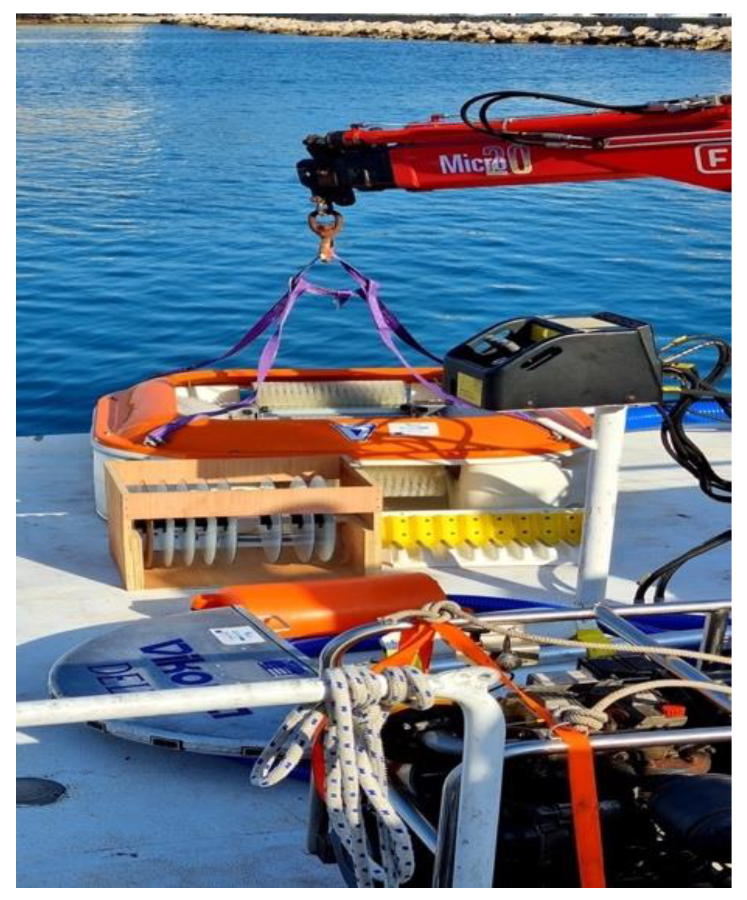
Figure 7 shows the preparation for testing disc, brush, and vacuum skimmers with the corresponding power pack. Testing in
Figure 7 took place on a calm sea according to the Beaufort scale. When testing various skimmer devices and other specialised equipment, real oil on the sea surface is usually not used due to the negative impact on flora and fauna. The oil can only be used for skimmer testing in specialised pools. For exercise and simulating oils, popcorns were used. This practice allows for an approximately accurate perception of the movement of spilt oil on the sea surface without endangering the marine environment.
5. Methodology of Oil Pollution Equipment Selection Criteria
The optimal pump for a given skimmer is selected based on the criterion of the match between the collection rate of the pump and the maximum possible collection rate that the skimmer can achieve. The goal is to minimise the absolute value of the difference between the characteristic speed of the pump and the skimmer. It is not necessary to have a higher speed pump on a vessel since it is not possible to use its full potential. It is also not feasible to have a lower speed pump since the potential of the vessel is not fully used. The following notations are introduced:
is the index from the set
of skimmers in a fleet,
is the maximum possible collection speed of the skimmer with index
,
is the index from the set
of all available pumps,
is the collection speed of the pump indexed by
, and
is the optimal pump for a ship with index
. Our goal was to determine:
This problem can have multiple solutions, so it is correct to say that it is a subset of
. However, in the context of the used software, a unique result corresponding to the pump with the lowest index was obtained. It might be useful to define the second optimal option denoted by
, namely:
An additional justification for this choice may be the reasonable assumption that the price of the pump is approximately proportional to its stated speed. Such a choice to achieve a minimum cost, or at least to be close enough to the minimum cost of equipping the vessel that simultaneously maximises the collection speed of the chosen pump–ship combination, is expected. Finding the optimal solution for a skimmer was carried out according to the following algorithm:
For each , determine .
Determine the minimum value from the set .
Determine the minimum value of the index which corresponds to the value , that is, determine the minimum value in a set .
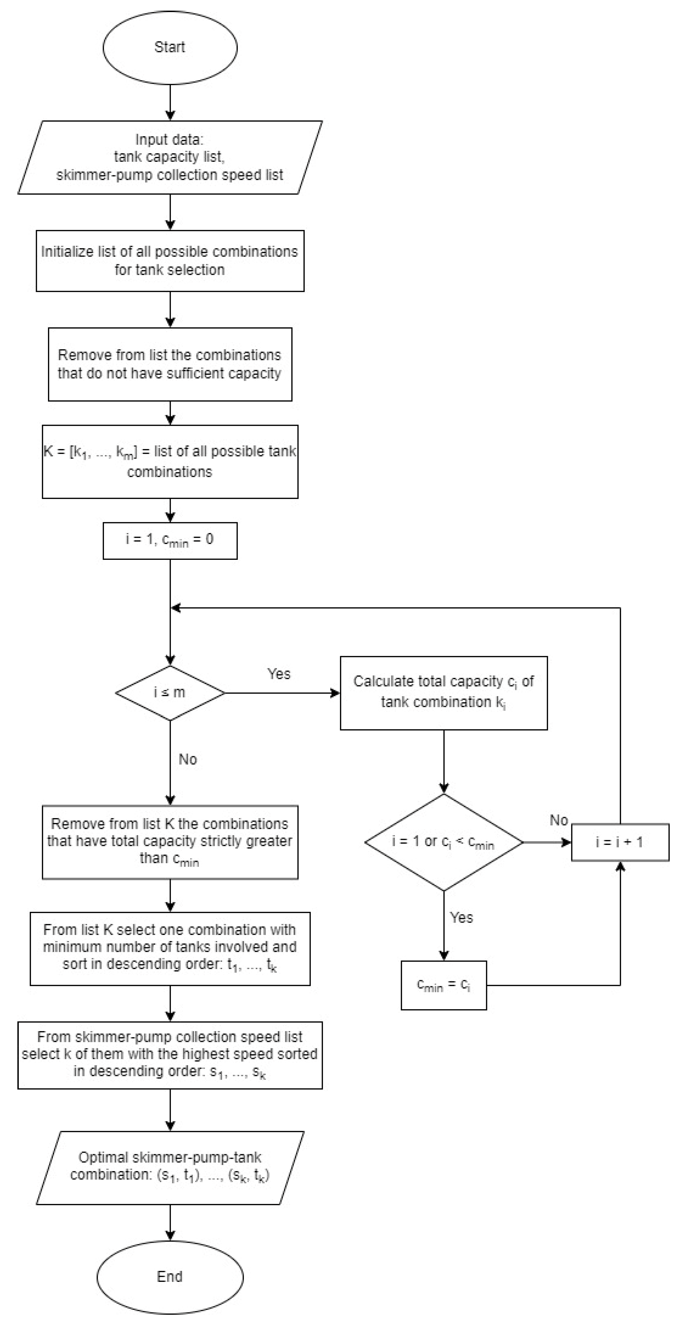
In addition, we suggest a storage optimisation algorithm to select the appropriate oil collection tank. We describe an algorithm for selecting appropriate tanks to collect a given amount of pollution. We assumed that it is known that the pollution has a volume of
and that we have
tanks available with a volume of
m
3, ...,
m
3. We first considered all possible combinations of tanks (all combinations where we took only one tank, all combinations where we took two tanks, etc.). Then, we discarded all tank combinations whose total volume (the sum of the tank volumes in that combination) was insufficient to store the total amount of pollution in them. We denote by
the set of all possible tank combinations that have sufficient storage volume. Next, we wanted to make the optimal choice of combinations in terms of volume in the sense that we considered the combination to be better if it had a smaller excess of total storage space relative to the pollution volume. In other words, we solved the following optimisation problem:
There may be several optimal solutions to this problem. To reduce their number, we gave preference to the combinations that involved the smallest possible number of tanks. In this way, we obtained the required choice of
tanks. The last step was to connect the tanks to the previously selected skimmer–pump pairs. Among all skimmer–pump pairs,
k with the highest collection speed was selected. A skimmer–pump pair with the highest speed was connected to a tank with the largest capacity, then a skimmer–pump pair with the second highest speed was connected to a tank with the second largest capacity, and so on. The respective flowchart is shown in
Figure 8.
6. Results
The authors calculated the optimal pump for each skimmer device. The speed of collecting oil from the sea surface depends on the capacity of the skimmer device and the speed of each pump. Data related to types of pumps and capacity are shown in
Table 2.
The skimmer’s efficiency was strongly influenced by the choice of the individual pump (
Table 2). The results showed a different speed of oil collection of each skimmer depending on which pump it was connected to. The results from the second column showed the optimal connection of each skimmer device with a specific pump, resulting in minimal losses in the capacity with maximal usability of the skimmer. For example, the first skimmer Foilex Micro has a maximum oil collection capacity of 15 m
3/h, and in connection to the Spate pump capacity of 14.4 m
3/h, losses were 0.6 m
3/h. This means that the skimmer on this pump is optimal, with an oil collection efficiency of 14.4 m
3/h. This is because the oil can be maximally collected at the fastest speed of a particular pump. The Mopmatic 1003 skimmer has a maximum oil collection capacity of 6.5 m
3/h. By connecting to the Rotoking gear pump, the loss was 0.7 m
3/h, and the skimmer could collect oil at its maximum capacity of 6.5 m
3/h. Twelve different skimmer devices with eleven different pumps, optimally connecting the skimmer to a specific pump to obtain maximum efficiency with the slightest capacity differences between equipment, are suggested. The differences in the capacities of individual skimmer devices with appropriate pumps are presented in
Figure 6,
Figure 7 and
Figure 8.
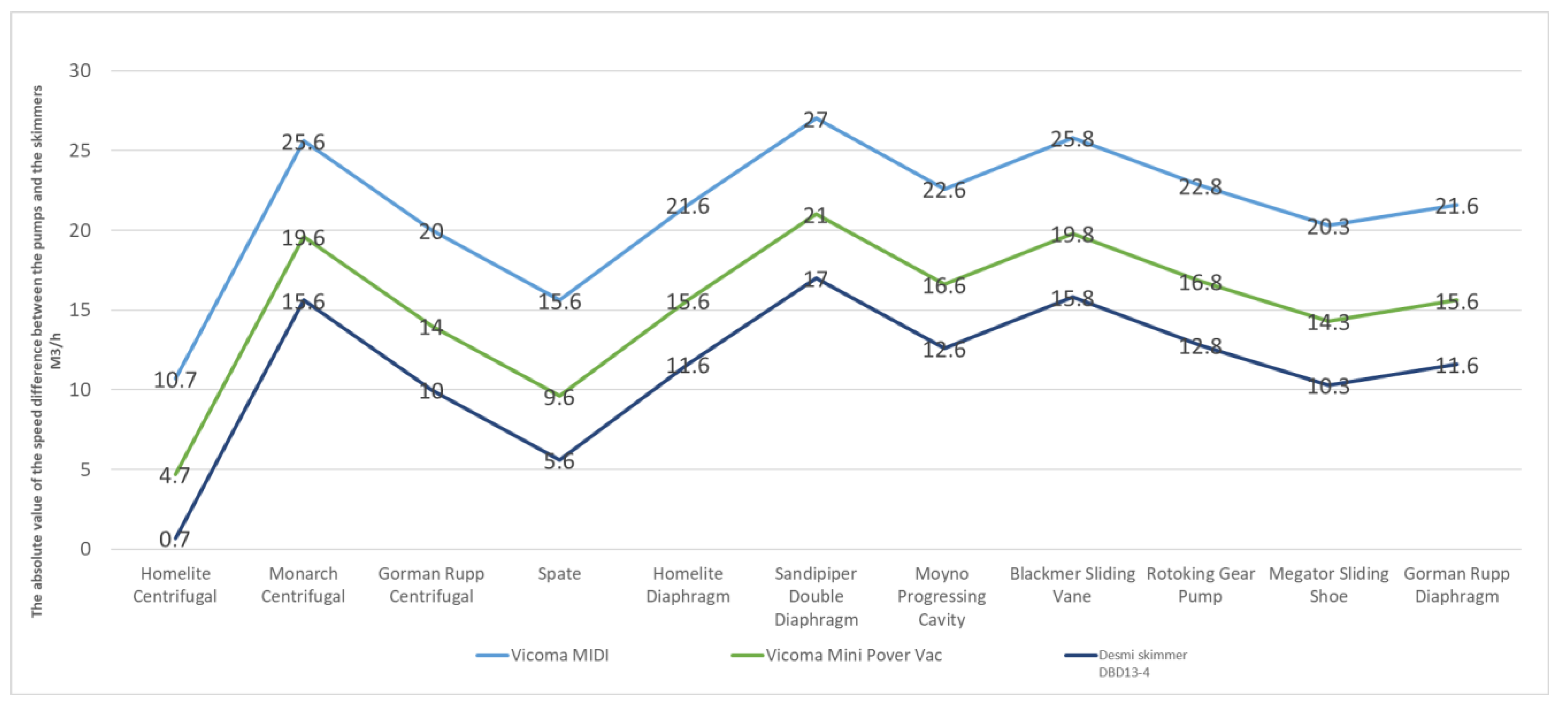
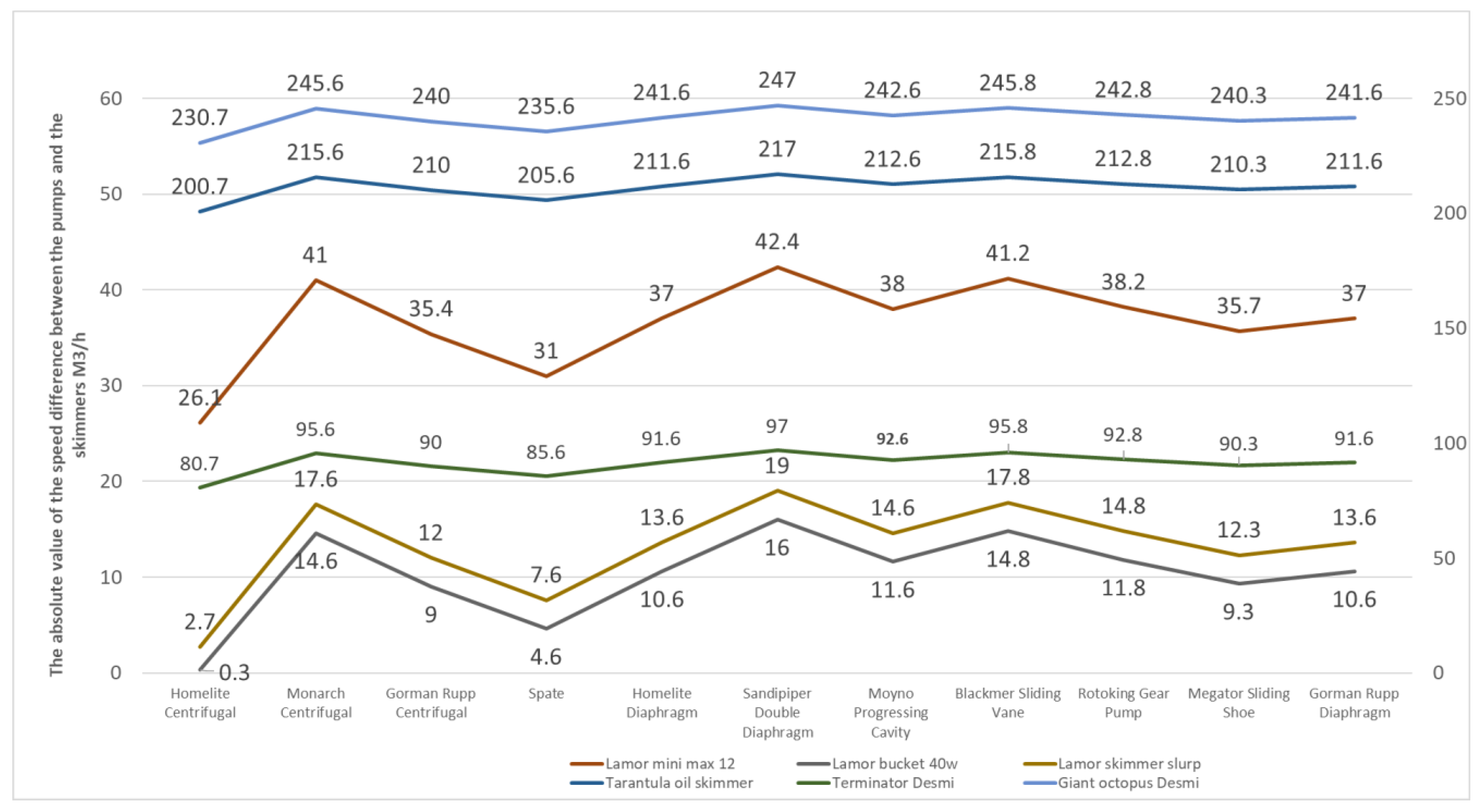
In
Figure 9,
Figure 10 and
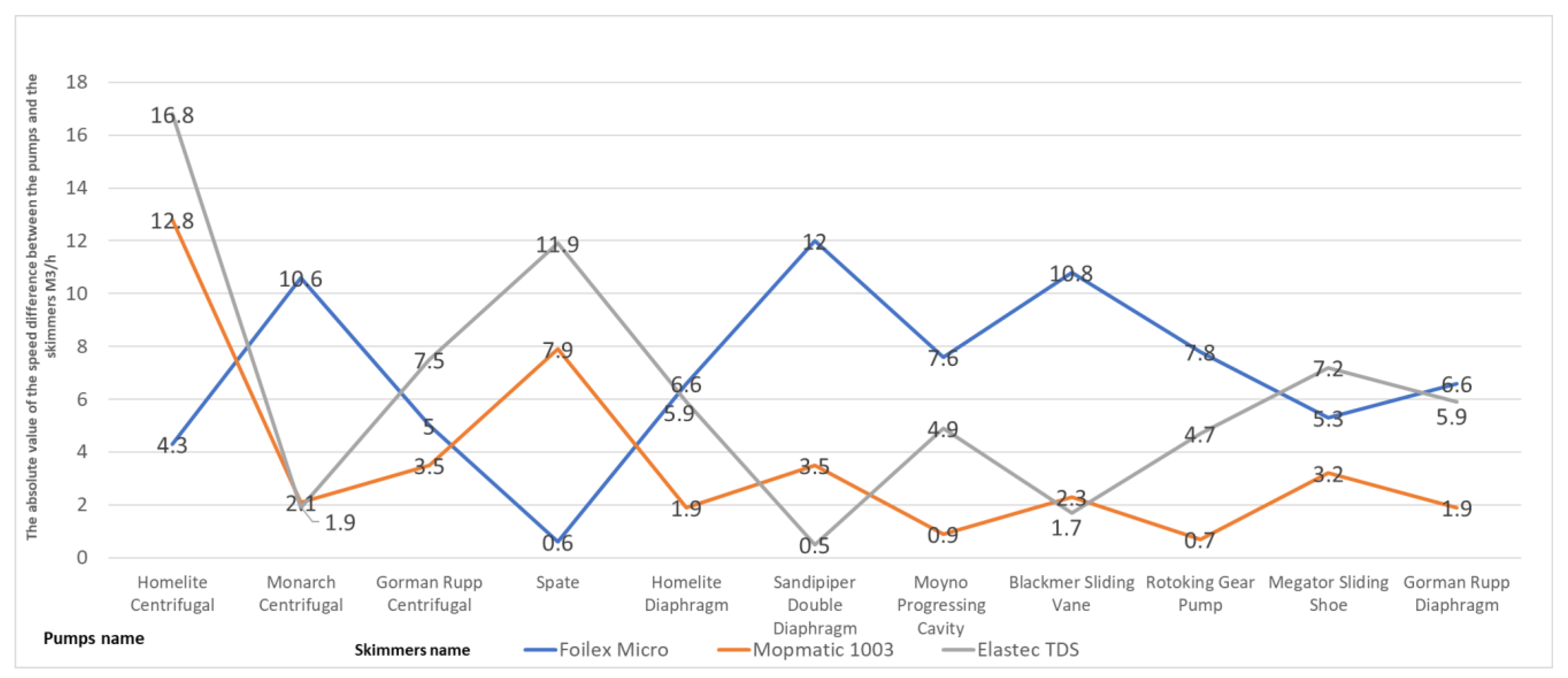
Figure 11, the Y-axes show the difference between the capacity of the skimmer and the capacity of the pumps.
Figure 9 shows how the Elastec TDS skimmer (Carmi, IL, USA) had an enormous efficiency deviation of 16.8 m
3/h when combined with the Homelite centrifugal pump (Anderson, SC, USA). This was the worst result among a group of other skimmers, while for example, the same skimmer connected to Sandpiper Double Diaphram pump (Mansfield, OH, USA) had a difference of only 0.5 m
3/h.
Figure 10 shows the results of the difference in the capacity of the Vicoma MIDI, Vicoma Mini Power Vac (Rotterdam, The Netherlands), and Desmi Skimmer DBD13-4 (Nørresundby, Denmark) skimmers with different pumps. For example, a Vicoma MIDI skimmer connected to a Homelite centrifugal pump had a loss of 10.7 m
3/h, which was also optimal for a Vicoma MIDI skimmer. For the skimmer Vicoma Mini Power Vac, by connecting to the pump Sandpiper Double Diaphragm, it had a loss of 21 m
3/h, which was the most significant loss compared to the connection to other pumps.
Figure 11 shows the absolute value of the speed difference between pumps and skimmers. Lamor Bucket 40 W, with the Homelite centrifugal pump, had a loss of 0.3 m
3/h. In
Figure 11, two axes indicate different scales and large deviations in skimmer capacities.
7. Discussion
Each skimmer has three main characteristics: capacity, efficiency, and flow efficiency. By definition, capacity is the speed by which the skimmer collects oil or other smaller particles from the sea [
36,
37]. In rough seas, the skimmer becomes less efficient and collects more significant amounts of seawater [
37]. The flow efficiency is the relationship between the collected oil and the oil that came in contact with the skimmer but was not collected. During the research, the authors divided skimmers into two separate categories. The first category was oleophilic skimmers such as disc, rope mop, and brush skimmers. The second category was weir skimmers. The authors recommend that the disc skimmer should be used for marine pollution with non-persistent oils such as gasoline, light types of diesel, and kerosene. The disc skimmer, which is easy to maintain and handle, is not sensitive to small and solid contaminants such as plastic plugs and can also be used to collect smaller fragments of plastic [
38]. The most significant disadvantage of disc skimmers is the weak efficiency in persistent oils such as crude oil and the sensitivity to ropes and river grasses due to constriction and discs. Thus, it is not recommended to use a skimmer disc in such areas. Furthermore, the mop skimmer collects the least seawater compared to the spilled oil on the sea surface [
39]. Because of its construction, it can cover large areas, and we recommend that it should be used on rivers and lakes, but not exclusively.
The most significant disadvantage of mop skimmers is the demanding installation and cleaning of individual parts after the intervention [
39,
40]. The brush skimmer shows the most excellent efficiency while removing persistent oils. It is also not sensitive to waves up to a height of 1 m. The most efficient oil collection from the sea surface is achieved by setting the speed from 30 to 40 revolutions per minute. The biggest disadvantage of the brush skimmer is demanding maintenance and installation at the place of contamination. Compared to other skimmers, weir skimmers collect larger amounts of spilled oil. Weir skimmers can be used for persistent and non-persistent oils. Large amounts of collected seawater represent an additional significant disadvantage. For this reason, larger tanks are also needed for the collected water–oil mixture. The weir skimmer shows a drop in efficiency in rough seas, where it begins to collect significantly more seawater than the spilled oil [
6]. Due to its construction, the weir skimmer is sensitive to smaller shards of plastic waste. The vacuum skimmer is excellent for use with non-persistent oils. It is also highly effective for use on rivers and lakes. The most significant disadvantage of vacuum skimmers is the requirement of specialised personnel. Additionally, a temporary waste tank has to be in the immediate vicinity. For any type of skimmer to effectively collect oil, a suitable pump is required. A pump with a power pack and a temporary waste disposal tank is a crucial piece of equipment for any skimmer device.
The main task of the pump is the transfer of oil from the skimmer to the temporary tank, whether at sea or on land [
41]. The efficiency of skimmers largely depends on the type of pump, as was confirmed in the conducted study. The correct skimmer and appropriate pump are vital for the rapid and efficient collection of oil from the sea surface. The pumps significantly lose the efficiency when collecting persistent oils. The authors suggest that pumps with larger hose diameters are used in persistent oil pollution scenarios, as this improves the efficiency of collecting pollution from the sea surface. The centrifugal and lobe pumps are most commonly used for accidental marine pollution. The centrifugal pump shows better efficiency with non-persistent oils, and it is connected directly to the power pack. These types of pumps take up very little space, and it is easy to store and transfer the pump to the site. The centrifugal pump is characterised by up to 3000 revolutions per minute. The lobe pump is used for persistent oils. This pump is very easy to maintain and is characterised by a long service life without significant failures.
8. Conclusions
Rapid response to accidental marine pollution as well as the selection of appropriate specialised equipment can lead to improvements in environmental protection and prevention of pollution aftermaths that can significantly impact flora and fauna. In accidental oil pollution, various pieces of specialised equipment are available to remove pollution from the sea surface. The authors analysed a mechanical method for removing oil using a skimmer device. The efficiency of oleophilic and weir skimmers and auxiliary equipment such as centrifugal and spate pumps were analysed. Research results showed that different skimmer devices had different efficiencies when collecting oil from the sea surface. The efficiency of an individual skimmer device depends on weather conditions and oceanographic parameters, such as tides and wave heights. Choosing the right skimmer with the right pump can result in faster and more efficient oil transfer from the skimmer to the temporary storage. The authors also suggested the importance of the pump because the efficiency of each skimmer device depends on a particular pump. Results showed significant differences in the efficiency of skimmer devices by connecting to different pumps. Almost every pump lost efficiency in more viscous oils such as bunker fuels used in maritime transport of goods and cargo by sea. In such cases, efficiency can be significantly improved by choosing a larger pump hose diameter. Each new pollution brings new challenges. Therefore, it is crucial to properly use specialised equipment, with knowledge of the duration of removing pollution from the sea surface. A quick reaction to accidental pollution with a trained team and well-arranged mechanical equipment leads to the preservation of the marine environment and contributes to the smooth circulation of maritime transport. These recommendations can contribute to faster, safer interventions in the event of accidental pollution at sea as well as on larger rivers and lakes.
The model results may be significantly affected by the uncertainty in the volume of oil spilled. The rest of the parameters are subject to small errors. In practice, the volume has the greatest uncertainty. Hence, one should insist on higher rather than the lower estimates. The oil collection speed of an individual skimmer device may differ from the characteristics given by the manufacturer. For example, in a more undulating sea, the skimmer may collect a larger amount of seawater along with the oil, while in smaller waves, the skimmer may have better efficiency. According to all mentioned reasons, there appears room for further work leading to research into the correlation of wave height and the impact on the efficiency of each skimmer device.
Author Contributions
Conceptualisation, M.Đ. and D.B.; methodology, M.Đ. and D.B.; software, M.Đ.; validation, M.Đ., D.B., Đ.M. and Đ.Š.; formal analysis, M.Đ. and Đ.M.; investigation, Đ.Š.; resources, D.B.; data curation, M.Đ. and D.B.; writing—original draft preparation, M.Đ.; writing—review & editing, D.B., Đ.Š. and Đ.M.; visualisation, M.Đ. and D.B.; supervision, D.B.; project administration, D.B. All authors have read and agreed to the published version of the manuscript.
Funding
This research received no external funding.
Institutional Review Board Statement
Not applicable.
Informed Consent Statement
Not applicable.
Data Availability Statement
Conflicts of Interest
The authors declare no conflict of interest.
References
- Review of Maritime Transport 2021. Available online: https://unctad.org/system/files/official-document/rmt2021_en_0.pdf (accessed on 20 May 2022).
- Protocol on Preparedness, Response and Co-Operation to Pollution Incidents by Hazardous and Noxious Substances. 2000. Available online: https://disasterlaw.ifrc.org/sites/default/files/media/disaster_law/2020-08/I627EN.pdf (accessed on 20 April 2022).
- Chae, C. Investigation of a Magnetic-Type Waterproof Oil Spill Stop Device for Ships. J. Mar. Sci. Eng. 2020, 8, 636. [Google Scholar] [CrossRef]
- Allahabady, A.; Yousefi, Z.; Tahamtan, R.; Sharif, Z. Measurement of BTEX (Benzene, Toluene, Ethylbenzene and Xylene) Concertation at Gas Stations. Environ. Health Eng. Manag. J. 2022, 9, 23–32. [Google Scholar]
- Pavlov, V.; Martins de Aguiar, V.C.; Hole, L.R.; Pongrácz, E. A 30-Year Probability Map for Oil Spill Trajectories in the Barents Sea to Assess Potential Environmental and Socio-Economic Threats. Resources 2022, 11, 1. [Google Scholar] [CrossRef]
- Smith, D.; Veitch, B.; Khan, F.; Taylor, R. Using the FRAM to Understand Arctic Ship navigation: Assessing Work Processes During the Exxon Valdez Grounding. Int. J. Mar. Navig. Saf. Sea Transp. 2018, 12, 455–456. [Google Scholar] [CrossRef]
- ITOPF. Available online: https://www.itopf.org/knowledge-resources/data-statistics/statistics/ (accessed on 24 June 2022).
- Kosheleva, R.; Kyzas, G.; Kokkinos, N.; Mitropoulos, A. Low-Cost Activated Carbon for Petroleum Products Clean-Up. Processes 2022, 10, 314. [Google Scholar] [CrossRef]
- Efe, B.; Faruk, O.; Ishizaka, A. A model Proposal to Examine the Effects of Ships to Marine Pollution in Terms of Internal and External Factors. Soft Comput. 2022, 26, 2121. [Google Scholar] [CrossRef]
- Zhu, Y.; Ma, W.; Feng, H.; Liu, G.; Zheng, P. Effects of Preparedness on Successful Emergency Response to Ship Accident Pollution Using a Bayesian Network. J. Mar. Sci. Eng. 2022, 10, 179. [Google Scholar] [CrossRef]
- Vikoma. Available online: https://www.vikoma.com/Oil_Spill_Solutions/Skimmers (accessed on 21 May 2022).
- Zafirakou, A.; Themeli, S.; Tsami, E.; Aretoulis, G. Multi-Criteria Analysis of Different Approaches to Protect the Marine and Coastal Environment from Oil Spills. J. Mar. Sci. Eng. 2018, 6, 125. [Google Scholar] [CrossRef] [Green Version]
- Ghannam, M.; Selim, M.; Zekri, A.; Esmail, N. Viscoelastic Behavior of Crude Oil-Gum Emulsions in Enhanced Oil Recovery. Polymers 2022, 14, 1004. [Google Scholar] [CrossRef]
- Dhaka, A.; Chattopadhyay, P. A Review on Physical Remediation Techniques for Treatment of Marine Oil Spills. J. Environ. Manag. 2021, 288, 112428. [Google Scholar] [CrossRef]
- Etkin, D.; Nedwed, T. Effectiveness of Mechanical Eecovery for Large Offshore oil spills. Mar. Pollut. Bull. 2021, 163, 111848. [Google Scholar] [CrossRef] [PubMed]
- Fingas, M. Chapter 5—Remote Sensing for Marine Management. In World Seas: An Environmental Evaluation, 2nd ed.; Ecological Issues and Environmental Impacts; Elsevier: Amsterdam, The Netherlands, 2019; Volume 3, pp. 103–119. [Google Scholar]
- Ulker, D.; Burak, S.; Balas, L.; Çağlar, N. Mathematical Modelling of Oil Spill Weathering Processes for Contingency Planning in Izmit Bay. Reg. Stud. Mar. Sci. 2022, 50, 102155. [Google Scholar] [CrossRef]
- El-Gayar, D.; Khodary, M.; Abdel-Aziz, H.; Khalil, M.F. Effect of Disk Skimmer Material and Oil Viscosity on Oil Spill Recovery. Water Air Soil Pollut. 2021, 232, 193. [Google Scholar] [CrossRef]
- Oil Spill Recovery Optimization Analysis. Available online: https://www.pwsrcac.org/wp-content/uploads/filebase/programs/oil_spill_response_operations/756.431.170201.NukaROA.pdf (accessed on 22 April 2022).
- Silva, I.; Almeida, F.; Souza, T.; Bezerra, K.G.; Durval, I.J.; Converti, A.; Sarubbo, L.A. Oil Spills: Impacts and Perspectives of Treatment Technologies with Focus on the Use of Green Surfactants. Environ. Monit. Assess. 2022, 194, 143. [Google Scholar] [CrossRef]
- Gan, Y.; Arjan, A.; Yik, J. Preparation of a Photosensitive Composite Carbnon Fiber for Spilled Oil Cleaning. J. Compos. Sci. 2022, 6, 28. [Google Scholar] [CrossRef]
- Hass Freeman, D.; Ward, C. Sunlight-driven Dissolution is a Major Fate of Oil at Sea. Sci. Adv. 2022, 8, 42–43. [Google Scholar] [CrossRef]
- Peša, I.; Ross, C. Extractive Industries and the Environment: Production, pollution, and protest in global history. Extr. Ind. Soc. 2021, 8, 100933. [Google Scholar] [CrossRef]
- Potter, S.; Morrison, J. World Catalog of Oil Spill Response Products; U.S. Department Interior Minerals Management Service: Ottawa, ON, Canada, 2017.
- Li, H.; Lin, H.; Huang, W.; Li, J.; Zeng, M.; Ma, J.; Hu, X. A New Prediction Method for the Complete Characteristics Curves of Centrifugal Pumps. Energies 2021, 14, 8580. [Google Scholar] [CrossRef]
- Luo, W.; Wang, Y.; Yan, Y.; Shi, Y.; Zhang, Z. Optimization of the Structural Parameters of a Plastic Centrifugal Pump in the Framework of a Flow Field Analysis. FDMP 2022, 18, 789–813. [Google Scholar] [CrossRef]
- Andrade-Cedeno, R.; Perez-Rodriguez, J.; Amaya-Jaramillo, C.; Rodriguez-Borges, C. Numerical Study of Constant Pressure Systems with Variable Speed Electric Pumps. Energies 2022, 15, 1918. [Google Scholar] [CrossRef]
- Zhang, Z.; Zhang, T.; Zhang, H.; Yang, J.; Cao, Y.; Jiang, Y.; Tian, D. Modeling, Kinematic Characteristics Analysis and Experimental Testing of an Elliptical Rotor Scraper Pump. Machines 2022, 10, 78. [Google Scholar] [CrossRef]
- Alubokin, A.; Gao, B.; Ning, Z.; Yan, L.; Jiang, J.; Quaye, E.K. Numerical Simulation of Complex Flow Structures and Pressure Fluctuation at Rotating Stall Conditions Within a Centrifugal Pump. Energy Sci. Eng. 2022, in press. [Google Scholar] [CrossRef]
- Svichkar, E.; Nikulin, N.; Klyucharov, V.; Demikhov, K.E. Molecular-Viscous Vacuum Pump (MVVP). AIP Conf. Proc. 2017, 1876, 020058. [Google Scholar]
- Bazaluk, O.; Dubei, O.; Ropyak, L.; Shovkoplias, M.; Pryhorovska, T.; Lozynskyi, V. Strategy of Compatible Use of Jet and Plunger Pump with Chrome Parts in Oil Well. Energies 2022, 15, 83. [Google Scholar] [CrossRef]
- Jia, X.; Yu, J.; Li, B.; Zhang, L. Effect of Incidental Angle of Wear-Ring Clearance on Pressure Pulsation and Vibration Performance of Centrifugal Pump. Front. Energy Res. 2022, 10, 861134. [Google Scholar] [CrossRef]
- He, T.; Li, Z.; Deng, H.; Chen, Q.; Wang, C.; Zhao, K. Flow Characteristics Analysis of a Balanced Valve Distribution Double-Row Axial Piston Pump. Mech. Sci. 2022, 13, 207–223. [Google Scholar] [CrossRef]
- Ozretić, V. Ship Auxiliary Machines and Devices, 1st ed.; Split Ship Management: Split, Croatia, 1996; pp. 134–239. [Google Scholar]
- Guo, L.; Li, B. Effect of Different Startup Models on the Cavitation Performance in Rotary Lobe Pump. Earth Environ. Sci. 2019, 240, 062046. [Google Scholar]
- Gao, X.; Dong, P.; Cui, J.; Gao, Q. Prediction Model for the Viscosity of Heavy Oil Diluted with Light Oil Using Machine Learning Techniques. Energies 2022, 15, 2297. [Google Scholar] [CrossRef]
- Cano, J.; Loza, J.; Guida, P.; Roberts, W.L.; Chejne, F.; Sarathy, S.M.; Im, H.G. Evaporation, break-up, and Pyrolysis of Multicomponent Arabian Light Crude Oil Droplets at Various Temperatures. Int. J. Heat Mass Transf. 2022, 183, 123–125. [Google Scholar]
- Zerebecki, R.; Heck, K.; Valentine, J. Biodiversity Influences the Effects of Oil Disturbance on Coastal Ecosystems. Ecol. Evol. 2022, 12, 23–28. [Google Scholar] [CrossRef]
- Yamada, K.; Yagishita, K.; Sato, K. Dispersion States of Lecithin-Soybean Oil Mixtures in Water. Colloid Polym. Sci. 2022, 300, 95–102. [Google Scholar] [CrossRef]
- Zhang, X.; Ni, W.; Sun, L. Fatigue Analysis of the Oil Offloading Lines in FPSO System Under Wave and Current Loads. J. Mar. Sci. Eng. 2022, 10, 225. [Google Scholar] [CrossRef]
- Manivel, R.; Sivakumar, R. Boat Type Oil Recovery Skimmers. Mater. Proc. 2020, 21, 470–473. [Google Scholar] [CrossRef]
| Publisher’s Note: MDPI stays neutral with regard to jurisdictional claims in published maps and institutional affiliations. |
© 2022 by the authors. Licensee MDPI, Basel, Switzerland. This article is an open access article distributed under the terms and conditions of the Creative Commons Attribution (CC BY) license (https://creativecommons.org/licenses/by/4.0/).


