Article

A Numerical Study on the Effects of Perforated and Imperforate Baffles on the Sloshing Pressure of a Rectangular Tank

by
Ahmad Mahamad Al-Yacouby
* and
Mostafa Mohamed Ahmed
Department of Civil and Environmental Engineering, Universiti Teknologi PETRONAS, Perak 32610, Malaysia
*
Author to whom correspondence should be addressed.
J. Mar. Sci. Eng. 2022, 10(10), 1335; https://doi.org/10.3390/jmse10101335
Submission received: 13 August 2022 / Revised: 3 September 2022 / Accepted: 5 September 2022 / Published: 20 September 2022
(This article belongs to the Section Ocean Engineering)

Abstract

:
Sloshing has many industry applications, namely in offshore engineering, aerospace, ship building, and manufacturing. Sloshing simulation is essential to better understand the sloshing pattern and consequently to improve the tank design to reduce noise levels, stresses on the structure, and optimize the baffle configurations and arrangements. Thus, the aim of this study is to determine the effects of perforated (porous) and imperforate (solid) baffles on the sloshing pressure using ANSYS FLUENT software based on Volume of Fluid (VOF) method where a rectangular tank with 25% and 60% filling ratios was considered. In the first case, an unbaffled rectangular tank with 60% filling ratio was used for the validation purpose, while in the second case, a 25% filling ratio was investigated considering two scenarios, namely a unbaffled tank and a baffled tank case with perforated and imperforate baffles. The outcomes of the results indicate that perforated baffle can significantly reduce the sloshing pressure in the tank. The validation of the results also shows a good agreement with the published experimental results.

1. Introduction

In the recent years, sloshing become an interesting engineering problem due to its extensive application in several fields, such as hydraulic, aerospace, transport and civil, and ocean and waterway engineering. Serious hydrodynamic loads in the sloshing tanks could be induced under the exterior exciting waves, which could lead to catastrophic consequences to the stability of the whole structure [1]. Therefore, efficient tools, such as perforated and imperforate baffles have been extensively applied in numerical and experimental studies using tanks with geometric shapes.
To investigate the sloshing effects, the moving particle semi-implicit (MPS) method was adopted by Jena and Biswal [2] during their numerical analysis, along with five modifications, namely: special approximation technique for the representation of gradient differential operator; enhanced source terms for pressure Poisson equation; collective action of mixed free surface particle identification boundary conditions; fixing discreetly the parting distance among particles to prevent collision; and impacting Neumann boundary condition on solving the PPE. They have clarified that the evaluation of developed dynamic forms during a severe sloshing motion, such as base shear, sloshing wave elevation, hydrodynamic pressure, overturning moment on the tanks’ ceiling, was not documented in the previous studies in the literature. Further, a numerical study by Wang and Arai [3] investigated the coupling interaction between LNG carrier responses and the sloshing problem under regular and irregular waves. They developed a time-domain numerical approach which comprises a vessel response solver based on strip theory and CFD sloshing solver. In their initial analysis, they have applied their own developed approach to investigate the coupling effect under regular wave in frequency domain to obtain the Response Amplitude Operator (RAO) results of ship motions along with the free surface motion elevations. Then, in their assumption of linearity of vessel motions and wave, they have applied the obtained RAO of ship motion in the regular waves case with coupling impact to generate time histories of ship motion in irregular waves. Sloshing Severity RAO (SSR) concept was introduced by Zheng et al. [4], whereas the wave elevation on the liquid sloshing was selected as a primary index to predict the sloshing severity. Then, they have compared with experimental data from a 3D normal model test to adjust the primary index and generate a new index. Furthermore, they have achieved sloshing severity under random wave conditions applying nonlinear sets of the new index. Based on the conventional Moss tank, a new concept of LNG tank shape was proposed to enhance the efficacy of the tank storage [5]. They have conducted a set of model tests for both a conventional Moss shape tank and a new shape tank under enforced regular and irregular sway motions. Furthermore, they have carried out a numerical study based on SPH method to track the sloshing problem as well as the swirling motion that may occurs in a 3D spherical tank (Moss tank). The coupled interaction between sloshing problem and FLNG responses was addressed by Kawahashi at al. [6], using numerical and experimental studies. In their numerical study, they have investigated the liquid sloshing using 3D finite difference method and FLNG motion using potential theory. They indicated that in both numerical and experimental results, the influence of sloshing was considerable for roll and sway responses. In addition, numerical and experimental studies were carried out by Luo et al. [7], in which a 3D numerical model was introduced by them in the scope of Consistent Particle Method (CPM). They have presented a precise boundary recognition approach to investigate the severe liquid sloshing. They clarified that the sloshing waves in the case of beam sea is the most severe and critically impacts the vessel motion stability. A numerical study was considered using ANSYS FLUENT software based on VOF multiphase method to simulate a tank fractionally filled with kerosene [8]. In their study, they have considered two cases, namely tank with baffles and tank without baffles to analyze the sloshing in terms of different time steps. They have pointed out that in the presence of baffles in the tank, the sloshing was remarkably mitigated compared to the tank without baffles. An experimental study was conducted by Kim et al. [9], using a set of model tests for three scaled membrane type tanks installed in LNG carrier. Different agitation frequencies and three loading conditions were presented in their tests for harmonic sway and roll motions. Moreover, they have conducted a statistical approach to analyze systematically the rise time of sampled sloshing pressures and pressure peak. Further, a comprehensive study was performed by Mahmud et al. [10], to demonstrate the sloshing problem for an offshore 3D ship. Their study combines a CFD analysis for robust sloshing simulations, the setup and measurement for a pilot-scale experimental testbed to validate their simulation, as well as applying an artificial neural network approach to predict the sloshing effect. Experimental and numerical approaches were utilized to investigate the coupling behavior between a rectangular ship and a rectangular tank under time and frequency domain [11]. In the case of frequency domain, they have used a superposition of natural sloshing modes to tackle the sloshing phenomena whereas Eigen-functions expansion for ship motions. In the case of time domain, nonlinear Boussinesq-type method based on velocity potential was applied to analyze the sloshing effects, while an impulse response function for solving the ship motions. An experimental scheme was performed using a membrane-type LNG tank to analyze the sloshing problem with two buoyant plates at three filling levels under harmonic roll agitation [12]. Primarily, their study was intended to evaluate the performance of damping tool and of relevant methods. They stated that the damping tool can efficiently suppress the wave runup along the longitudinal bulkhead and the effective pressure acting on the bulkhead under the moderate agitation heights particularly at the top of the tank. Additionally, they conducted a numerical scheme based on CFD program to carry out a further investigation. A new concept of moving baffles which consists of a spring system as one of the mechanisms for sloshing mitigation was experimentally presented [13]. A set of numerical simulations was carried out to examine the effects of various tank shapes, such as membrane LNG tank, cylindrical, rectangular and spherical tanks, on the sloshing motions under horizontal agitation using OpenFOAM v10 [14]. Their results showed that the membrane tank was subjected to lower effective pressure than the cylindrical, rectangular, and the spherical tanks. Modulated 3D Moving Particle Semi-Implicit (MPS) approach was utilized by Wang et al. [15], to supplement the numerical simulation of sloshing load in LNG tank subjected to multidegree agitation movement. They compared the numerical analysis with their experimental results and 2D computations gained by other researchers to verify the accuracy. A numerical method consists of density stratified layers of liquid water and oil within a rectangular tank was modeled by Kargbo et al. [16], to act reciprocally with a rigid perforated T-shaped baffle under sloshing cases. A hybrid solution algorithm which combines a 3D potential flow solver for barge dynamics into a viscous flow solver for sloshing forces, was developed by Saripilli [17]. A numerical approach was developed to examine the sloshing loads in an actual scaled rectangular tank when the LNG carrier is moving in sea states [18]. They employed a level set approach to simulate the liquid and gas at the same time as well as to address the severe sloshing motion. Based on Lattice Boltzmann Method (LBM), a numerical study was employed to investigate the efficacy of vertical baffles of various configurations in dampening severe transient sloshing [19]. Moreover, they simulated a severe wave-breaking phenomenon at limited water depths under resonance cases employing VOF and large eddy simulation (LES) methods. An air trapping mechanism was utilized by Kim et al. [20] to restrain the effective sloshing pressure in a 2D rectangular tank, which is equipped with horizontal baffles in two sides.
An efficient mechanism for suppressing the sloshing problem was presented numerically by Ye et al. [21], using coaxial dual arc-shaped or circular perforated structures in a cylindrical tank. Based on the linear potential theory, a semi-analytical solution along with the scaled boundary finite element method (SBFEM) for addressing the sloshing problem was used. An iso-geometric scaled boundary finite element method (IGA-SBFEM) applying the non-uniform rational B-splines (NURBS) was initially carried out to examine the sloshing loads within the half-full horizontal annular cylindrical tank with the interior structure [22]. A novel type of double-side curved baffle was proposed to evaluate its impact on mitigating the sloshing effects in a rectangular tank under surge and pitch excitation [23]. They have carried out numerical and experimental studies to compare this innovative type with the T-baffle, conventional baffles, and effects of the vertical baffle on reducing the sloshing and to analyze the free surface wave elevation as well as the hydrodynamic pressure on the tank wall. According to Ma et al. [24], the influence of baffle location on the liquid sloshing in a laterally moving spherical tank has been investigated. SPH method was used to simulate weakly compressible viscous flow in the fractionally filled tank. To monitor the pressure exerted on the tank wall, four probes are placed at various locations within the tank wall. Furthermore, to investigate how the sloshing phenomenon is suppressed, four tank models with different baffle locations were created. The incompressible Smoothed Particle Hydrodynamic (ISPH) method was applied by Zheng et al. [25] to simulate the sloshing in a 2D tank with complex baffles. Different sloshing tanks were simulated under varied conditions to investigate the impact of the baffle configuration and excitation frequency. The findings indicated that the complex baffles can considerably influence the impact pressures on the wall induced by the severe sloshing, and the relevant analysis can assist find the engineering solutions to efficiently repress the problem. According to Chen et al. [26], an in-house mesh-free particle solver MLParticle-SJTU was developed based on improved moving particle semi-implicit (MPS) method, was employed to simulate numerically the impacts of T-baffle on liquid sloshing under surge excitation. They have indicated that the MLParticle-SJTU solver can capture the complicated flow phenomena, such as breaking waves, impacting the roof of the tank, overturning of free surface, and so on. The transient sloshing in sideways oscillated horizontal elliptical tanks with T-shaped baffles has been first analyzed by utilizing an innovative semi-analytical scaled boundary finite element method (SBFEM) [27]. A pseudoparabolic equations were carried out using spectral meshless radial point interpolation method (SMRPI), and singular boundary method (SBM), respectively [28,29]. The purpose of this study is to investigate the effects of perforated and imperforate baffles on the sloshing pressure of a rectangular tank using ANSYS FLUENT 2021 R2 software based on VOF method to capture the free surface problem. Two case studies were considered using a rectangular tank with filling level of 25% and 60%, respectively. In the first case, 60% filling level of unbaffled rectangular tank was considered for the validation purpose, while in the second case, 25% filling level was further investigated under two scenarios, unbaffled tank scenario and baffled tank scenario with perforated and imperforate baffles. The outline of the remaining sections is Section 2 that covers the methodology of the recent study, Section 3 covers results and discussions and validation of the results, finally Section 4 illustrates the conclusion and recommendations for future works.

2. Methodology

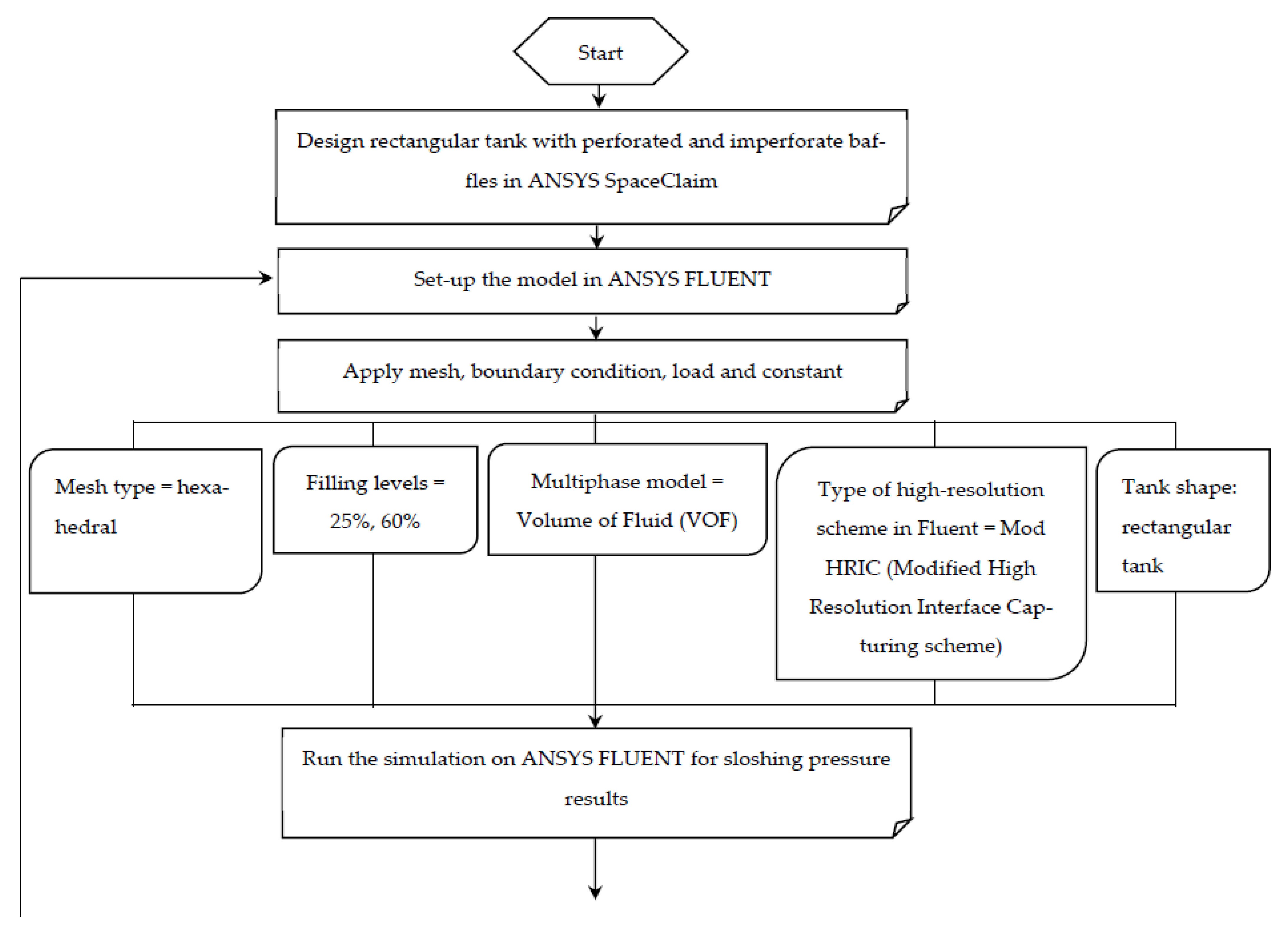
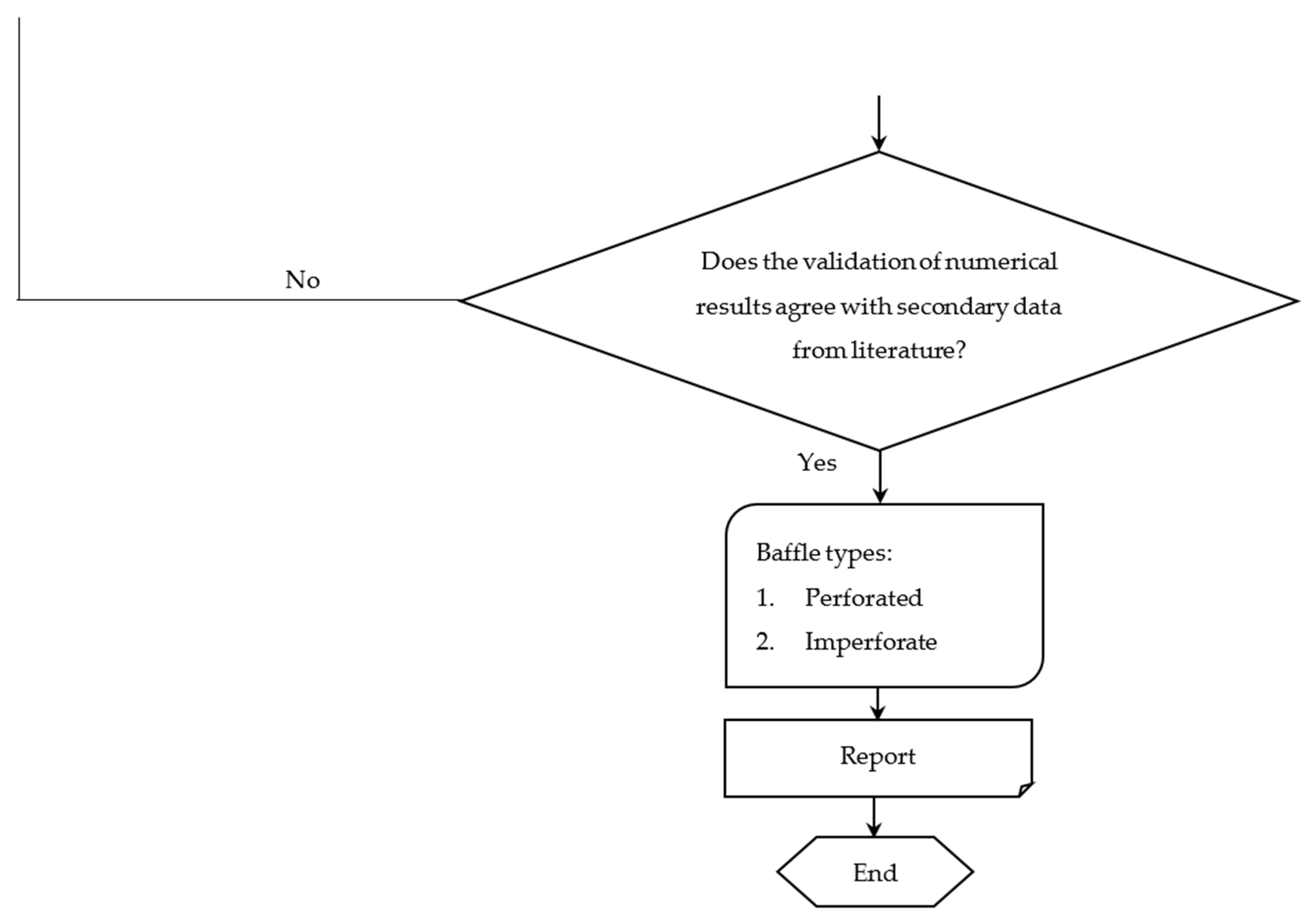
2.1. Numerical Flow of ANSYS Software

The flowchart of this numerical study is represented to illustrate the processes that have been applied in ANSYS software for a rectangular tank with perforated and imperforate baffles as described in Figure 1.

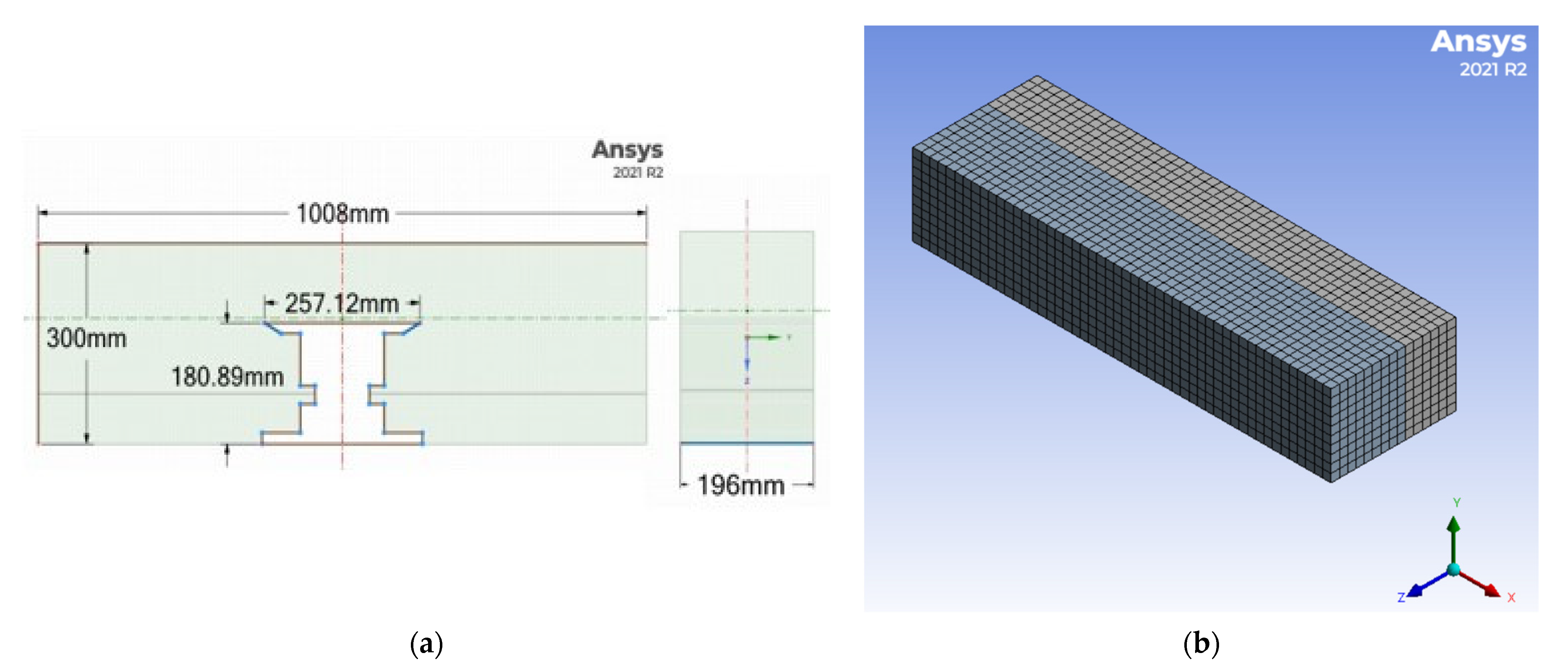
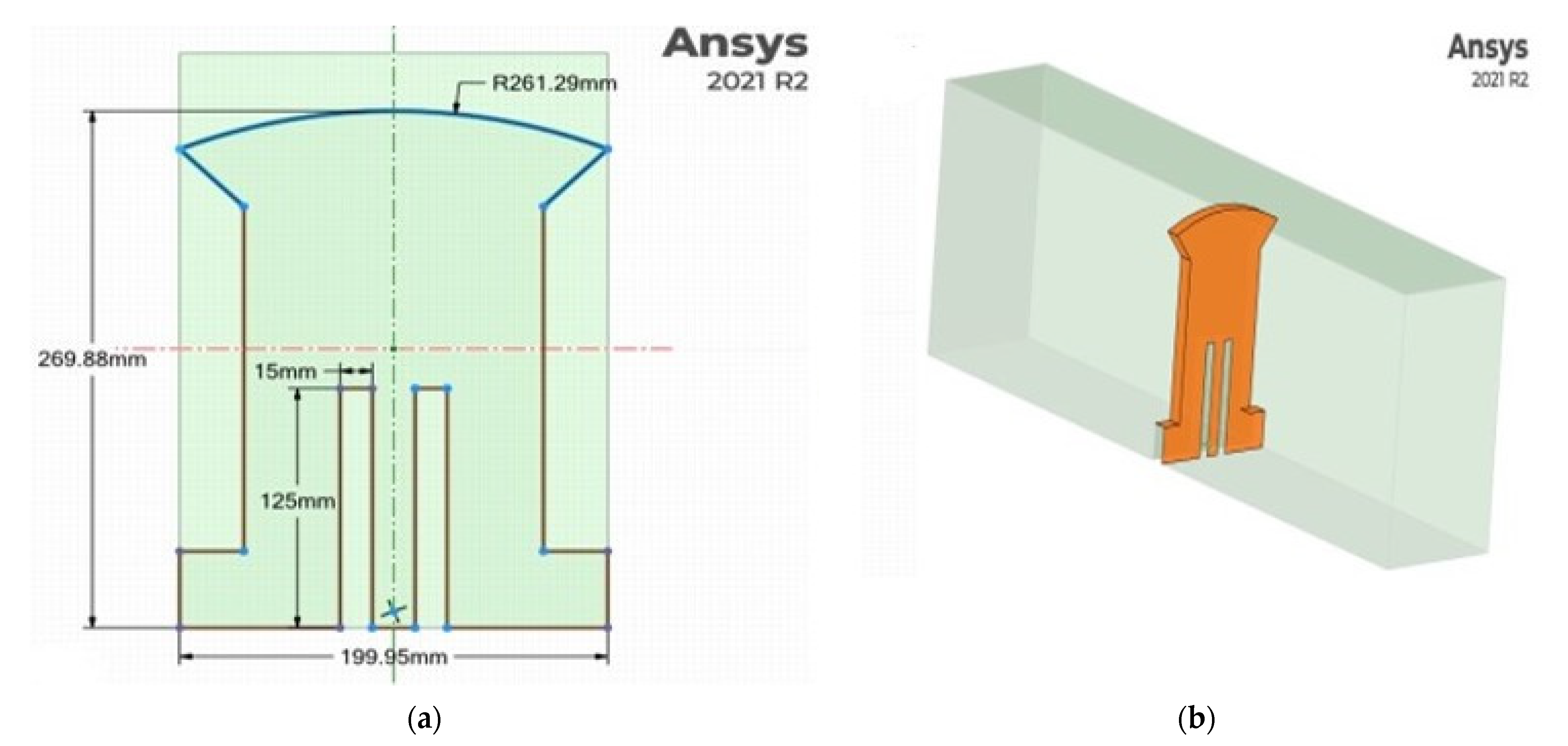
2.2. Geometrical Particulars of Rectangular Tank and Baffles

The essential particulars of the rectangular tank is based on Agrawal and Rahumathulla [30], which are adopted to design the model in ANSYS SpaceClaim considering perforated and imperforate baffles. Table 1 represents the required particulars of the rectangular tank, perforated and imperforate baffles, and hexahedral mesh with a maximum size of 20 mm. Figure 2a shows the dimensions of the rectangular tank with imperforate baffle, whereas Figure 2b shows the generated mesh of the rectangular tank. Figure 3 shows the dimensions of perforated baffle and isometric view of rectangular tank with perforated baffle in ANSYS SpaceClaim.

2.3. Theoretical Background

Volume of Fluid (VOF) Method in ANSYS Fluent

The sloshing pressure is normally analyzed based on transient multiphase (air and water) simulation [30]. VOF method was utilized to track the sloshing pressure problem in a rectangular tank using ANSYS FLUENT. If the volume fraction of one fluid in the cell is indicated as α, then the following three conditions are possible:
  • α = 0; the cell is empty
  • α = 1; the cell is full
  • 0 < α < 1; the cell is partially filled and contains the interface
Summation of volume fraction for all the fluids should be equal to one.
α α = 1 .
Volume fraction equation is given as:
α t + . ( u α ) = 0 .
Total continuity equation for incompressible fluid:
. u = 0 .
A single momentum equation is solved throughout the domain, and the resulting velocity field is shared among the phases.
ρ u t + . ( ρ u u ) = p + . T = + F b .
Here T = is the viscous stress tensor.
The properties in total continuity and momentum equations are volume weighted averaged properties.
Transient terms are discredited utilizing Bounded second order time implicit formulation which provides better steadiness for multiphase flows and allows using greater time steps. For convective terms by applying Gauss’ divergence theorem, volume integrals can be converted to surface integral. In the volume fraction equation, face values of volume fraction utilized in the convection term are discretized applying the second order reconstruction scheme based on slope limiters.
The SST model is a hybrid two-equation model that incorporates the merits of both k-epsilon and k-omega models. The k-epsilon and k-omega models are mixed such that the SST model functions, such as the k-omega close to the wall and the k-epsilon model in the free stream. The SST model combines a damped cross-diffusion derivative term in the equation. The definition of the turbulent viscosity is adjusted to consider for the transfer of the turbulent shear stress. Turbulence was modeled utilizing SST k-omega model with turbulence damping to capture fluid shearing impact at the gas-liquid interface. The following series of equations are solved in SST k-omega turbulence model [31].
( ρ k ) t + x j ( ρ k u j ) = x j [ Γ k k x j ] + G k Y k + S k ,
( ρ ω ) t + x j ( ρ w u j ) = x j [ Γ w ω x j ] + G w Y w + S w + D w .
In these equations, G k indicates the generation of turbulence of kinetic energy due to mean velocity gradients. indicates the generation of w, Γ k and Γ w indicate the impactful diffusivity of k and w, respectively. Y k and Y w indicate the dissipation of k and w due to turbulence. D w indicates the cross-diffusion term. S k and S w are user-defined source terms.

3. Results and Discussion

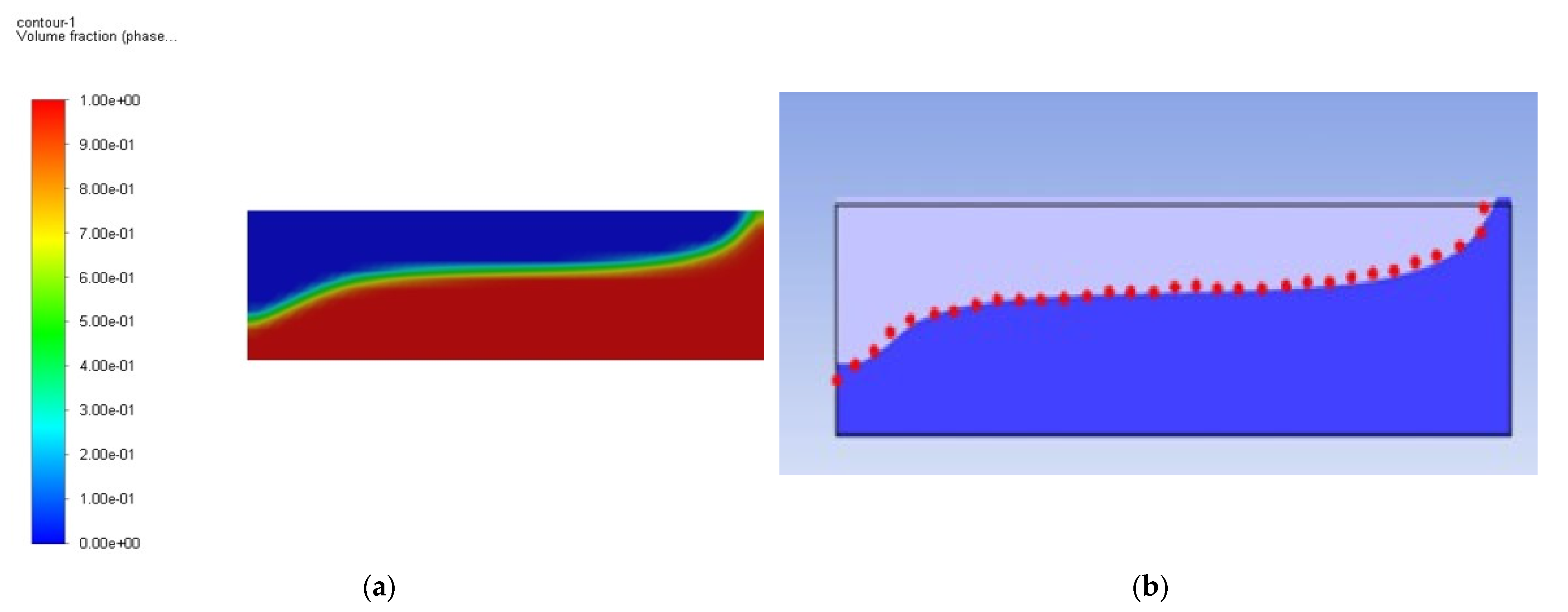
3.1. Validation of Sloshing Pressure Results in Unbaffled Rectangular Tank under 60% Filling

The numerical study mainly focused on the effects of sloshing pressure in unbaffled rectangular tank using ANSYS FLUENT based on VOF method under 60% filling level. One of the high resolution schemes that was applied in this study is Modified High Resolution Interface Capturing (Mod HRIC) scheme in which FLUENT solver utilizes to discretize the convective term in the equation for transfer of the volume fraction [32].
Figure 4 describes the comparison of Bounded 2nd order time discretization between the present study, numerical data [30], and the experimental data [33], the red dotted line, under 60% filling level. The prediction of 2nd order discretization scheme in terms of momentum equations can give better outcomes as compared to power law scheme and first order.
The validation of sloshing pressure results is in good agreement with the numerical data [30], and the experimental data [33]. The maximum sloshing pressure result obtained in the current study is 3.099 bar, while the numerical data [30], with value of 3.189 bar and the experimental data [33] with value of 3.327 bar as demonstrated in Table 2. Figure 5 shows the comparison of the sloshing pressure findings in the case of unbaffled tank between the present study, and the established numerical and experimental data under 60% filling ratio with total time of 80 ms.

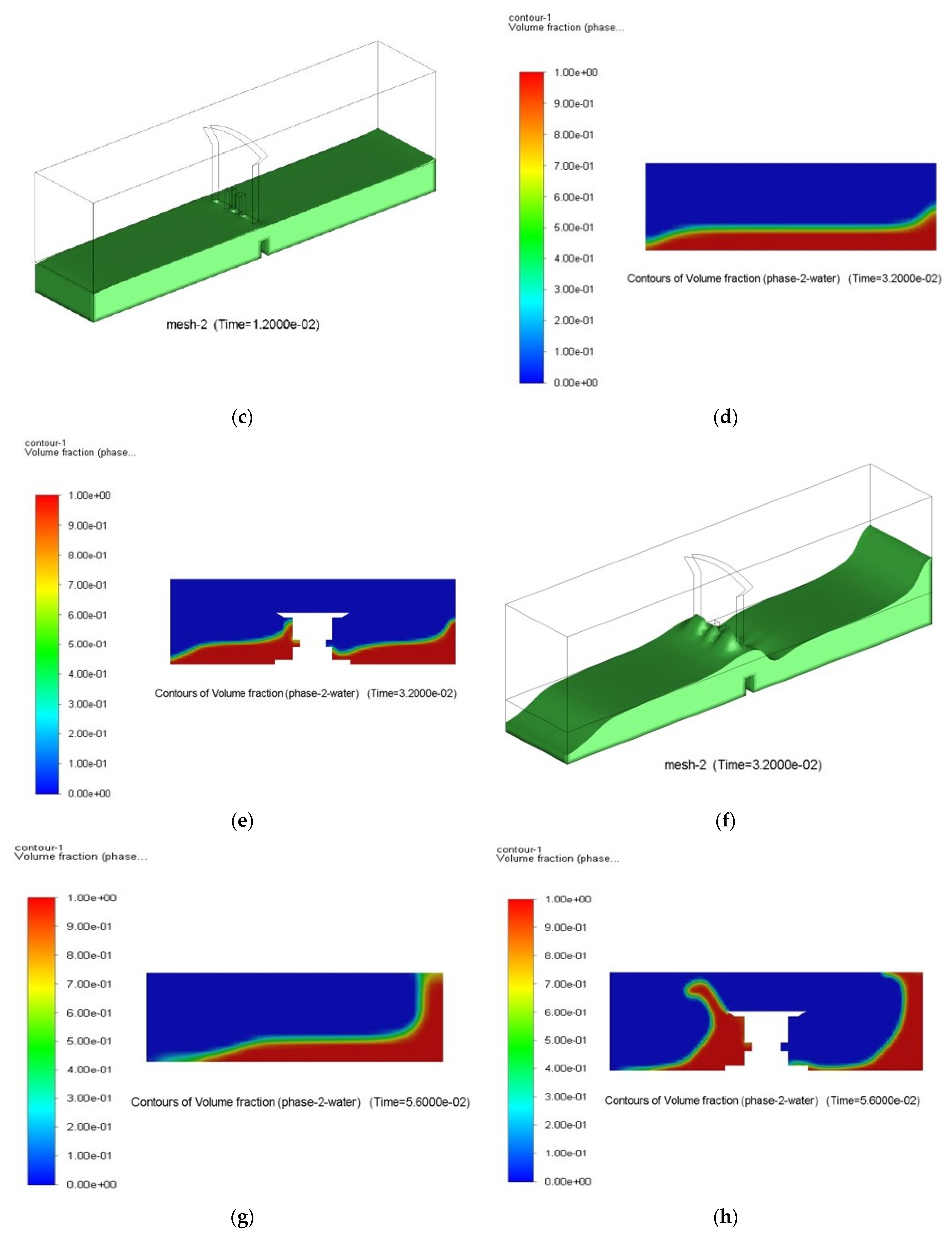
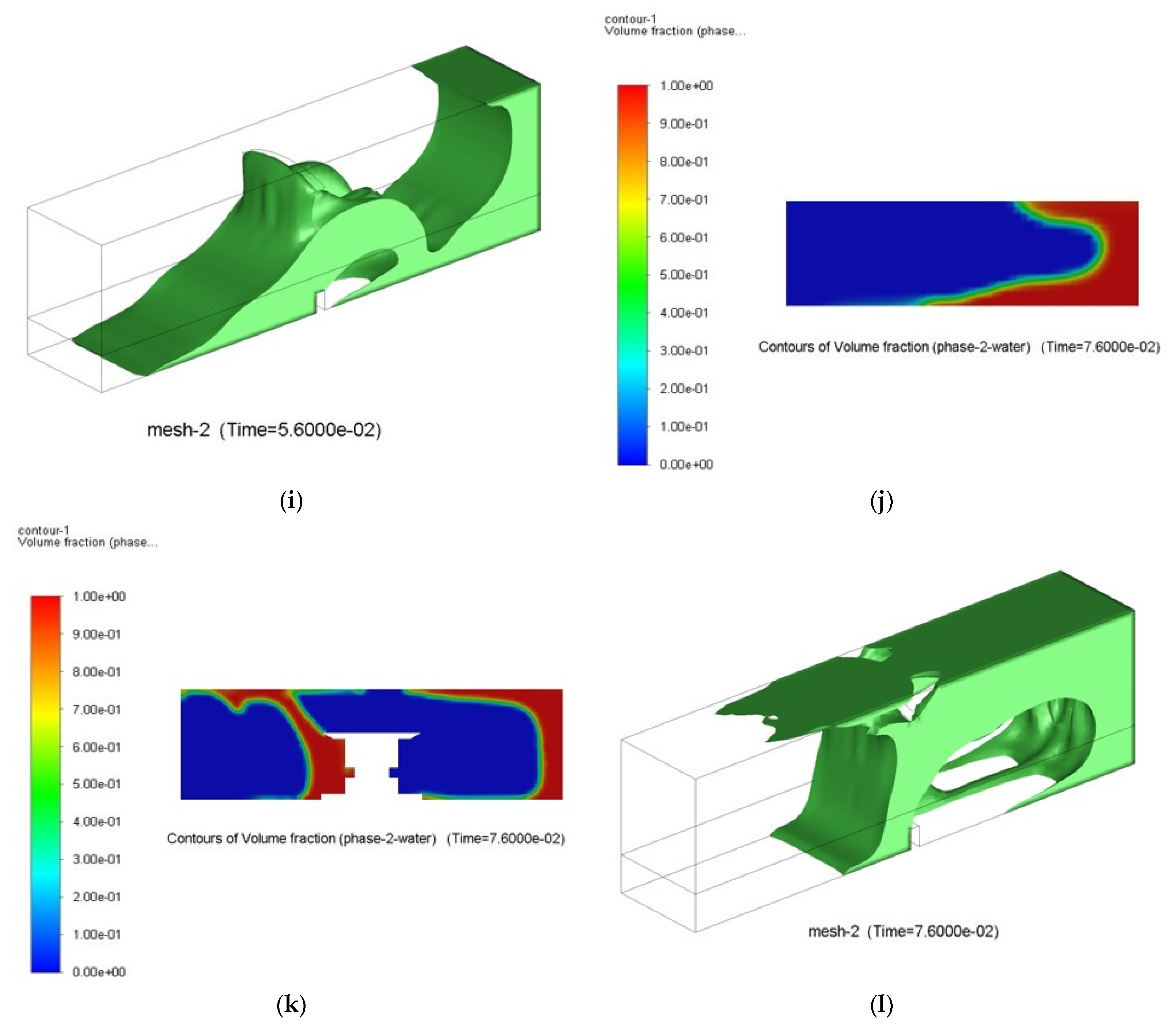
3.2. Comparison of Sloshing Pressure between Unbaffled and Baffled Tanks under 25% Filling

On the other hand, the illustrative comparison of the contour of volume fraction results is shown in Figure 6. The volume fraction results at different periods under three cases, unbaffled tank in Figure 6a,d,g,j, baffled tank with imperforate baffle in Figure 6b,e,h,k, and baffled tank with perforated baffle as shown in Figure 6c,f,i,l, respectively, are represented to show the various performance of each case on the sloshing pressure at different tank wall’s locations.
Figure 7 illustrates the comparison of sloshing pressure results for the three scenarios under 25% filling level. From the graphs, it is observed that the lowest sloshing pressure, associated with the perforated baffle case, was recorded as 0.886 bar, while for the imperforate baffle, the sloshing pressure was 0.891 bar, and lastly, the highest sloshing pressure occurred in the case of unbaffled tank, with a pressure value of 0.982 bar. Generally, the variation of sloshing pressure with time for the case without baffle is comparatively smooth, with the higher values, while introducing the baffle has slightly reduced the maximum sloshing pressure in the tank. The graphs also show that introducing a perforated baffle resulted in irregular pressure distribution in the tank.

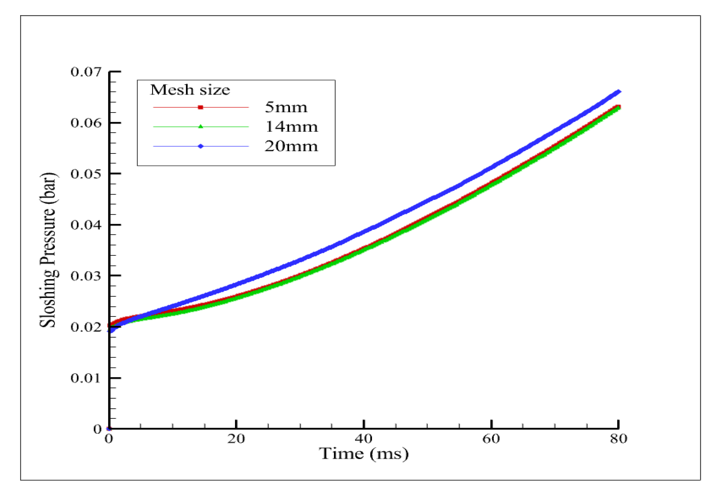
3.3. Mesh Sensitivity Analysis

The effect of mesh parameters, such as the mesh size and mesh type, on the results was taken into consideration. Thus, to evaluate the mesh sensitivity on the sloshing pressure for unbaffled tank under 25% filling level, for the different cases shown in Table 3 and Figure 8 were evaluated.
The three mesh types investigated are Automatic, Tetrahedral, and Hexahedral, with 5 mm, 14 mm, and 20 mm mesh sizes, respectively. The max sloshing pressure recorded for Automatic (5 mm), Tetrahedral (14 mm), and Hexahedral (20 mm) are 0.0632 bar, 0.0629 bar, and 0.0661 bar, respectively.
Furthermore, the impact of viscous models on the sloshing pressure was also investigated using Laminar, SST k-omega, and k-epsilon models as presented in Table 4.
The max sloshing pressure under the different viscous models are presented in Figure 9. The max sloshing pressure occurred under Laminar, SST k-omega, and k-epsilon models are 0.9032 bar, 0.9309 bar, and 1.9317 bar, respectively. This indicates that Laminar SST k-omega predict similar sloshing pressure, while the k-epsilon model is showing comparatively higher sloshing pressure.

4. Conclusions

In this study, numerical investigation was conducted to determine the effects of perforated and imperforate baffles on the sloshing pressure of a rectangular tank using ANSYS Fluent software based on VOF method. Two different conditions that consist of 25% and 60% filling levels were investigated. In the first case, an unbaffled tank with 60% filling level was considered for validation purpose, while in the second case, 25% filling was considered under two scenarios. This includes unbaffled tank and baffled tank with perforated and imperforate baffles. From the simulation results, the following points can be drawn:
  • The analysis of sloshing pressure for a rectangular tank with perforated and imperforate baffles under 25% and 60% filling rates was discussed and presented. The validation of the correlation of the sloshing pressure results under 60% filling level for the unbaffled tank case is found to be in good agreement with the numerical data published by Agrawal and Rahumathulla [30] and the experimental data by Vesenjak et al. [33].
  • On the other hand, the 25% filling level was extensively investigated considering three conditions: unbaffled tank, baffled tank with perforated baffle, and baffled tank with imperforate baffle for addressing the sloshing pressure problem. It is remarkably observed that the lowest sloshing pressure was in the case of perforated baffle with value of 0.886 bar, followed by the imperforate baffle with value of 0.891 bar, and finally the unbaffled tank with a pressure value of 0.982 bar.
Based on the above, it is recommended to conduct further numerical and experimental studies to quantify the effects of different baffle dimensions, locations, and configurations of perforated and imperforate baffles on suppressing the sloshing loads considering various parameters, such as sloshing force and wave elevations in different tank geometries.

Author Contributions

Conceptualization and methodology, A.M.A.-Y.; validation, M.M.A.; formal analysis, A.M.A.-Y. and M.M.A.; investigation, A.M.A.-Y.; resources and supervision, A.M.A.-Y.; original draft preparation, A.M.A.-Y. and M.M.A.; writing—review and editing, A.M.A.-Y. All authors have read and agreed to the published version of the manuscript.

Funding

This research was funded by Yayasan UTP, grant numbers 015LC0-95 and 015LC0-313, and GR&T research grant number 015MD0-123.

Institutional Review Board Statement

Not applicable.

Informed Consent Statement

Not applicable.

Data Availability Statement

Not applicable.

Acknowledgments

The authors would like to acknowledge the continued support by Universiti Teknologi PETRONAS (UTP).

Conflicts of Interest

The authors declare no conflict of interest, and the funders had no role in the design of the study; in the collection, analyses, or interpretation of data; in the writing of the manuscript; or in the decision to publish the results.

References

  1. Choudhary, N.; Bora, S.N. Linear sloshing frequencies in the annular region of a circular cylindrical container in the presence of a rigid baffle. Sādhanā 2017, 42, 805–815. [Google Scholar] [CrossRef]
  2. Jena, D.; Biswal, K.C. A numerical study of violent sloshing problems with modified MPS method. J. Hydrodyn. 2017, 29, 659–667. [Google Scholar] [CrossRef]
  3. Wang, X.; Arai, M. A numerical study on coupled sloshing and ship motions of a liquefied natural gas carrier in regular and irregular waves. Proc. Inst. Mech. Eng. Part M J. Eng. Marit. Environ. 2015, 229, 3–13. [Google Scholar] [CrossRef]
  4. Zheng, M.Z.; Gou, Y.; Teng, B.; Jo, H. A practical prescreening method for sloshing severity evaluation. Pet. Sci. 2020, 17, 1119–1134. [Google Scholar] [CrossRef]
  5. Ma, C.; Oka, M.; Ando, T. A Study on Sloshing Behavior for Moss-type LNG Tank Based on SPH Numerical Simulation and Large-scale Model Experiment. Int. J. Offshore Polar Eng. 2018, 28, 350–360. [Google Scholar] [CrossRef]
  6. Kawahashi, T.; Arai, M.; Wang, X.; Cheng, L.Y.; Nishimoto, K.; Nakashima, A. A study on the coupling effect between sloshing and motion of FLNG with partially filled tanks. J. Mar. Sci. Technol. 2019, 24, 917–929. [Google Scholar] [CrossRef]
  7. Luo, M.; Koh, C.G.; Bai, W. A three-dimensional particle method for violent sloshing under regular and irregular excitations. Ocean Eng. 2016, 120, 52–63. [Google Scholar] [CrossRef]
  8. Singal, V.; Bajaj, J.; Awalgaonkar, N.; Tibdewal, S. CFD analysis of a kerosene fuel tank to reduce liquid sloshing. Procedia Eng. 2014, 69, 1365–1371. [Google Scholar] [CrossRef]
  9. Kim, S.; Kim, Y.; Lee, J. Comparison of sloshing-induced pressure in different scale tanks. J. Ships Off. Str. 2016, 5302, 1744–5302. [Google Scholar] [CrossRef]
  10. Mahmud, M.A.; Khan, I.; Wang, S.; Xu, Q. Comprehensive Study on Sloshing Impacts for an Offshore 3D Vessel via the Integration of Computational Fluid Dynamics Simulation, Experimental Unit, and Artificial Neural Network Prediction. Ind. Eng. Chem. Res. 2020, 59, 22187–22204. [Google Scholar] [CrossRef]
  11. Su, Y.; Liu, Z.Y. Coupling effects of barge motion and sloshing. Ocean Eng. 2017, 140, 352–360. [Google Scholar] [CrossRef]
  12. Yu, Y.; Ma, N.; Fan, S.; Gu, X. Experimental and numerical studies on sloshing in a membrane-type LNG tank with two floating plates. Ocean Eng. 2017, 129, 217–227. [Google Scholar] [CrossRef]
  13. Kim, S.; Chung, S.; Shin, W.; Cho, D.; Park, J. Experimental study on sloshing reduction effects of baffles linked to a spring system. Ocean Eng. 2018, 170, 136–147. [Google Scholar] [CrossRef]
  14. Xue, M.; Chen, Y.; Zheng, J.; Qian, L.; Yuan, X. Fluid dynamics analysis of sloshing pressure distribution in storage vessels of different shapes. Ocean Eng. 2019, 192, 106–582. [Google Scholar] [CrossRef]
  15. Wang, C.; Guo, C.; Han, F. LNG Tank Sloshing Simulation of Multidegree Motions Based on Modified 3D MPS Method. Math. Probl. Eng. 2020, 4018925. [Google Scholar] [CrossRef]
  16. Kargbo, O.; Xue, M.; Zheng, J.; Yuan, X. Multiphase sloshing dynamics of a two-layered fluid and interfacial wave interaction with a porous T-shaped baffle in a tank. Ocean Eng. 2021, 229, 108664. [Google Scholar] [CrossRef]
  17. Saripilli, J.R. Numerical Studies of Coupling Effect of Sloshing on 3D Ship Motions. Int. J. Offshore Polar Eng. 2017, 27, 27–35. [Google Scholar] [CrossRef]
  18. Bai, W.; Liu, X.; Koh, C.G. Numerical study of violent LNG sloshing induced by realistic ship motions using level set method. Ocean Eng. 2015, 97, 100–113. [Google Scholar] [CrossRef]
  19. Ma, C.; Xiong, C.; Ma, G. Numerical study on suppressing violent transient sloshing with single and double vertical baffles. Ocean Eng. 2021, 223, 108557. [Google Scholar] [CrossRef]
  20. Kim, H.; Parthasarathy, N.; Choi, Y.; Lee, Y. Reduction of sloshing effects in a rectangular tank through an air-trapping mechanism—A numerical study. J. Mech. Sci. Technol. 2018, 32, 1049–1056. [Google Scholar] [CrossRef]
  21. Ye, W.; Liu, J.; Lin, G.; Zhou, Y.; Yu, L. High performance analysis of lateral sloshing response in vertical cylinders with dual circular or arc-shaped porous structures. Appl. Ocean Res. 2018, 81, 47–71. [Google Scholar] [CrossRef]
  22. Wang, W.; Peng, Y.; Wei, Z.; Guo, Z.; Jiang, Y. Engineering Analysis with Boundary Elements High performance analysis of liquid sloshing in horizontal circular tanks with internal body by using IGA-SBFEM. Eng. Anal. Bound. Elem. 2019, 101, 1–16. [Google Scholar] [CrossRef]
  23. Zhu, A.; Xue, M.A.; Yuan, X.; Zhang, F.; Zhang, W. Effect of Double-Side Curved Baffle on Reducing Sloshing in Tanks under Surge and Pitch Excitations. Shock Vib. 2021, 6647604. [Google Scholar] [CrossRef]
  24. Ma, L.; Wei, C.; Zhao, Y. Research on the Suppression Effect Law of Different Baffle Positions on Liquid Sloshing in Spherical Tank. In Proceedings of the 2018 9th International Conference on Mechanical and Aerospace Engineering (ICMAE), Budapest, Hungary, 10–13 July 2018; pp. 457–461. [Google Scholar] [CrossRef]
  25. Zheng, X.; You, Y.; Ma, Q.; Khayyer, A.; Shao, S. Applied sciences A Comparative Study on Violent Sloshing with Complex Baffles Using the ISPH Method. Appl. Sci. 2018, 8, 904. [Google Scholar] [CrossRef]
  26. Chen, X.; Tang, Z.; Wan, D. The effects of T type baffle on liquid sloshing by MPS method. In Proceedings of the 3rd International Conference on Violent Flows (VF-2016), Osaka, Japan, 9–11 March 2016; pp. 9–11. [Google Scholar]
  27. Wang, W.; Tang, G.; Song, X.; Zhou, Y. Transient Sloshing in Partially Filled Laterally Excited Horizontal Elliptical Vessels with T-Shaped Baffles. J. Press. Vessel Technol. Trans. ASME 2017, 139, 1–13. [Google Scholar] [CrossRef]
  28. Shivanian, E.; Aslefallah, M. Stability and convergence of spectral radial point interpolation method locally applied on two-dimensional pseudoparabolic equation. Numer. Methods Partial Differ. Equ. 2017, 33, 724–741. [Google Scholar] [CrossRef]
  29. Aslefallah, M.; Abbasbandy, S.; Shivanian, E. Meshless singular boundary method for two-dimensional pseudo-parabolic equation: Analysis of stability and convergence. J. Appl. Math. Comput. 2020, 63, 585–606. [Google Scholar] [CrossRef]
  30. Agrawal, M.; Rahumathulla, L. Numerical simulation of liquid sloshing in floating LNG. In Proceedings of the Annual Offshore Technology Conference, Houston, TX, USA, 5–8 May 2014; Volume 3, pp. 1848–1858. [Google Scholar] [CrossRef]
  31. Menter, F.R. Zonal two equation k-w turbulence models for aerodynamic flows. In Proceedings of the AIAA 24th Fluid Dynamics, Plasmadynamics, and Lasers Conference, Orlando, FL, USA, 6–9 July 1993. [Google Scholar]
  32. Waclawczyk, T.; Koronowicz, T. Comparison of cicsam and hric high-resolution schemes for interface capturing. J. Theor. Appl. Mech. 2008, 46, 325–345. [Google Scholar]
  33. Vesenjak, M.; Müllerschön, H.; Hummel, A.; Ren, Z. Simulation of Fuel Sloshing—Comparative Study. 2004. Available online: https://www.semanticscholar.org/paper/Simulation-of-Fuel-Sloshing-Comparative-Study-Verfahren-Vesenjak/23c434469e479820e214973a905c15d3b1e53db6 (accessed on 1 April 2022).
Figure 1. Numerical flow of rectangular tank with perforated and imperforate baffles in ANSYS Fluent software.
Jmse 10 01335 g001aJmse 10 01335 g001b
Figure 2. Schematic diagram showing: (a) Dimensions of rectangular tank with imperforate baffle; (b) Generated mesh of rectangular tank.
Jmse 10 01335 g002
Figure 3. Schematic diagram showing: (a) dimensions of perforated baffle; (b) isometric view of the rectangular tank with perforated.
Jmse 10 01335 g003
Figure 4. Comparison of Bounded 2nd order time discretization between: (a) Present study, (b) Numerical data [30], and experimental data [33], (red dotted line).
Jmse 10 01335 g004
Figure 5. Sloshing pressure results for the case of unbaffled rectangular tank under 60% filling ratio.
Jmse 10 01335 g005
Figure 6. Comparison of the volume fraction results snapshots at various times under 25% filling; (a,d,g,j) Unbaffled tank, (b,e,h,k) Baffled tank with imperforate baffle, (c,f,i,l) Baffled tank with perforated baffle.
Jmse 10 01335 g006aJmse 10 01335 g006bJmse 10 01335 g006c
Figure 7. Comparison of sloshing pressure effect between unbaffled and baffled rectangular tanks with perforated and imperforate baffles under 25% filling ratio.
Jmse 10 01335 g007
Figure 8. Comparison of mesh sensitivity effect on sloshing pressure in unbaffled rectangular tank under 25% filling ratio.
Jmse 10 01335 g008
Figure 9. Comparison of viscous models effect on sloshing pressure in unbaffled rectangular tank under 25% filling ratio.
Jmse 10 01335 g009
Table 1. Required particulars of rectangular tank, and baffles [30].
DesignationDimensions
Rectangular tank
Length (mm)1008
Breadth (mm)196
Height (mm)300
Imperforate baffle parameters
Length (mm)257.12
Height (mm)180.89
Perforated baffle parameters
Length (mm)199.95
Height (mm)269.88
Hole Length (mm)15
Hole Height (mm)125
Baffle arc radius (mm)261.29
Mesh parameters
Mesh typeHexahedral
Maximum mesh size20 mm
Number of elements7500
Number of nodes8976
Table 2. Comparison of the max sloshing pressure of unbaffled rectangular tank under 60% filling ratio in the present result and numerical and experimental results from literature.
Max Sloshing Pressure (Bar)
Present StudyNumerical Study [30]Experimental Study [33]
3.0993.1893.327
Table 3. Comparison of mesh sensitivity study.
Mesh TypeMesh SizeSloshing Pressure (Bar) under 25% Filling Rate for Unbaffled Tank
Automatic5 mm0.0632
Tetrahedral14 mm0.0629
Hexahedral20 mm0.0661
Table 4. Comparison of three viscous models and their impacts on sloshing pressure under 25% filling rate.
Type of Viscous ModelSloshing Pressure (Bar) under 25% Filling Rate for Unbaffled Tank
Laminar0.9032
SST k-omega0.9309
k-epsilon1.9317
Publisher’s Note: MDPI stays neutral with regard to jurisdictional claims in published maps and institutional affiliations.

