Article

Optimization Design and Experiment of Soil-Covering Device for Astragalus Mulching Transplanting Machine

1
College of Mechanical and Electrical Engineering, Gansu Agricultural University, Lanzhou 730070, China
2
College of Humanities, Gansu Agricultural University, Lanzhou 730070, China
3
Gansu Institute of Desertification Control, Lanzhou 730073, China
*
Author to whom correspondence should be addressed.
Agriculture 2025, 15(7), 769; https://doi.org/10.3390/agriculture15070769
Submission received: 7 March 2025 / Revised: 28 March 2025 / Accepted: 31 March 2025 / Published: 2 April 2025
(This article belongs to the Section Agricultural Technology)

Abstract

:
In response to the low efficiency and poor soil quality of the mechanized transplanting of Astragalus, and in combination with the agronomic requirements of Astragalus mulching and outcrop cultivation, an Astragalus film mulching transplanting machine was designed, which integrates functions such as trenching, seedling feeding, mulching, and seed row soil covering. Firstly, based on the analysis of the overall structure of the transplanting machine, the structure and working principle of the soil-covering device are expounded, and the structure and working parameters of the soil-covering disc and soil-covering drum are clarified. In order to optimize the performance of the soil-covering device of the mulching transplanting machine and improve the quality of the covering soil, the Box–Behnken response surface test design method was adopted. The depth of disc extraction, the disc deflection angle, and the rotation speed of the soil-covering drum were selected as the main influencing factors. The quantity of soil cover and variation coefficient of soil cover quantity uniformity were used as the evaluation indicators for the quality of the operation, and parameter optimization experiments were conducted. By establishing a regression mathematical model between influencing factors and evaluation indicators, analyzing the interactive effects of each factor on response values, and comprehensively optimizing the model, the optimal parameter combination was obtained. The results of field experiments show that when the depth of disc extraction is 95 mm, the disc deviation angle is 40°, and the rotation speed of the soil-covering drum is 30 r/min, the corresponding quantity of soil cover and variation coefficient of soil cover quantity uniformity are 10.61 kg/m and 1.79%, respectively, which can meet the soil covering requirements. The research results can provide technical references for the structural optimization and performance improvement of the soil-covering device of the traditional Chinese medicine mulching transplanting machine.

1. Introduction

Astragalus is an herbaceous plant belonging to the legume family, characterized by its sweet and slightly warm nature. It is known for its various health benefits, including strengthening the body, tonifying middle-Jiao and Qi, promoting diuresis and reducing swelling, protecting the liver, and lowering blood pressure [1]. This plant is commonly utilized as a key ingredient in traditional Chinese medicine formulas and daily health care practices. There are two primary methods for cultivating Astragalus: direct sowing and seedling transplantation [2]. However, direct sowing results in low germination and survival rates, and the growth cycle typically exceeds two years before the active ingredients reach optimal levels [3]. Consequently, seedling transplantation has become the predominant approach for cultivating Astragalus. This method not only mitigates the adverse effects of natural disasters, such as low temperatures and frost, on medicinal seedlings but also enhances their survival rates, increases both the yield and quality of medicinal materials, shortens the cultivation cycle, reduces costs, and ultimately boosts production [4,5,6]. Currently, Astragalus transplantation primarily relies on manual labor, which is associated with high labor intensity, low production efficiency, and elevated operating costs, thereby significantly hindering the large-scale development of the Astragalus industry. Therefore, implementing mechanized transplantation of Astragalus is crucial for reducing labor costs and enhancing production efficiency.
Internationally, research on transplanters primarily focuses on the transplanting of bowl seedlings for crops such as rice, tobacco, and vegetables [7,8,9]. However, due to distinct differences in plant morphology, transplanting depth, and transplanting requirements between Astragalus seedlings and the bowl seedlings of other crops, existing crop transplanters or their improved versions are inadequate for meeting the agronomic needs of Astragalus transplantation. In response to the demand for the mechanical transplantation of traditional Chinese medicinal materials, domestic researchers have recently conducted relevant studies on transplanting machines tailored for traditional Chinese medicine [10,11,12,13,14,15]. Nevertheless, the research and development of transplanting machines in China began relatively late and has progressed slowly, and the structural design of traditional Chinese medicine transplanting machines often lacks integration with agronomic principles. What is more, most developed machines either do not incorporate film-covering mechanisms or possess such mechanisms but fail to achieve cross-row soil covering, necessitating manual seedling placement. Consequently, the planting costs are elevated, and these machines do not fulfill the agronomic requirements for Astragalus film-covering cultivation in the arid northwest regions.
The film mulching technique has the functions of collecting rain, suppressing steam, preserving moisture, and increasing temperature. Agricultural technicians in the northwest arid regions combined the traditional drought resistance techniques with the cultivation agronomic requirements of root and stem Chinese medicinal materials to create a film-covered outcrop cultivation model of Chinese medicinal materials. This model can not only effectively resist drought but also inhibit weed growth and achieve a significant increase in income, with a yield increase of more than 20% compared to conventional trenching cultivation [16]. At present, it has been widely applied in the planting of Chinese medicinal materials in a large area in the northwest arid regions. Therefore, how to achieve mechanized transplanting that meets the agronomic requirements of film-covered outcrop cultivation has become an urgent problem that needs to be solved in the cultivation of traditional Chinese medicine. Shen et al. [17] designed a grooved-wheeled Astragalus transplanting machine; field tests showed that the machine runs smoothly, and the various operational quality assessment indicators are close to the agronomic technical requirements, but when the tractor output shaft speed is lower than 550 r/min, the mulching will not be in place, and when it is higher than 700 r/min, the soil will be piled up in the center of the seedling ditch, and the soil-covering device still needs to be further improved and optimized in design. Li et al. [18] conducted a key analysis on the mechanized ridge planting and transplanting of Astragalus and Codonopsis pilosula, and developed a ridge planting, film covering, and soil covering transplanting machine for root and stem Chinese medicinal materials (Astragalus and Codonopsis pilosula). The transplanting method of the machine is ridge planting, film covering, and soil covering cultivation (1 ridge, 2 rows), which can effectively reduce labor intensity, but the work efficiency is not high. Bai [19] designed an organic Astragalus transplanting, film laying, and drip irrigation integrated machine, determined the working parameters of the whole machine, and designed the parameters of key components such as the transplanting mechanism, film laying mechanism, and drip irrigation mechanism, but did not involve the design and research of soil covering mechanism. Wang et al. [20] designed a semi-automatic transplanting equipment to address the low level of mechanization in the transplantation and planting of root and stem Chinese medicinal materials such as Astragalus and Codonopsis pilosula. Through field experiments, it was found that the amount of soil covering on the film was insufficient, and it could not be continuously covered with soil, and further optimization and improvement were needed. Zhu et al. [21] designed a ridge and film-covering transplanting machine for Astragalus seedlings based on Astragalus planting agronomy. According to the homework requirements, the parameters of key components, such as land preparation, ridge formation, seedling transportation, and film covering, were determined and optimized, but the soil covering mechanism was not optimized. These Astragalus mulching transplanting machines are still in the theoretical research and experimental stage, mostly focusing on the design and optimization of the devices for land preparation, furrowing, seedling starting, and seedling transplanting, while less research has been carried out on the relationship between the technical parameters of the soil-covering device and the mulching performance of the mulching transplanter. Soil covering is a key link in the process of outcrop cultivation, which directly affects the effect and quality of mechanized transplanting operations. If the amount of soil covering is insufficient, it may lead to the film not being firmly pressed, and the film may be easily blown up by the wind and unraveled, which will lose the function of drought-resistance and moisture preservation; if the amount of soil covering is too large, the film, though firmly pressed, will be easy to slate, and the seedlings will have difficulty in arching, which will decrease the rate of seedling emergence, and then influence the growth and yield of the Chinese herbs in the later stage of the planting process. Therefore, optimizing the design of the soil-covering device and improving the mulching performance of the transplanting machine can guarantee the advantages of Astragalus mulching outcrop cultivation technology.
This study focuses on the agronomic requirements for cultivating Astragalus using mulching film. To optimize the design of the soil-covering device in the mulching transplanting machine and improve the quality of the covering soil, both structural and operational parameters of the device are theoretically analyzed. Additionally, the influence of various factor parameters on the quality of the covering soil for the Astragalus film is investigated. Orthogonal experiments are conducted utilizing the Box–Behnken Design response surface optimization method to identify the optimal parameter combination for soil covering operation quality. Field experiments are then carried out for verification, providing a technical reference for enhancing the soil covering performance of traditional Chinese medicine mulching transplanting machines.

2. Materials and Methods

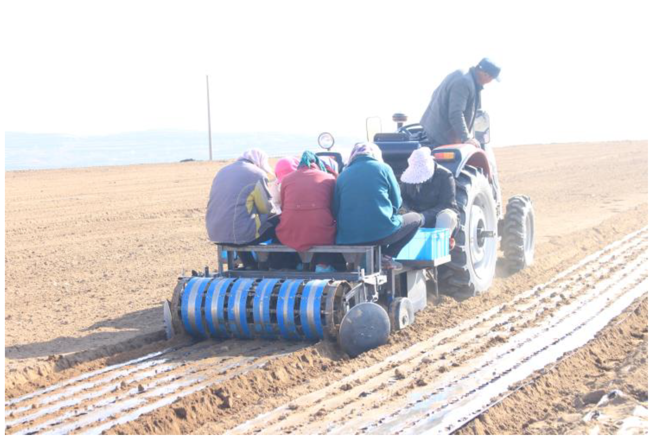
2.1. Whole Machine Structure and Working Principle

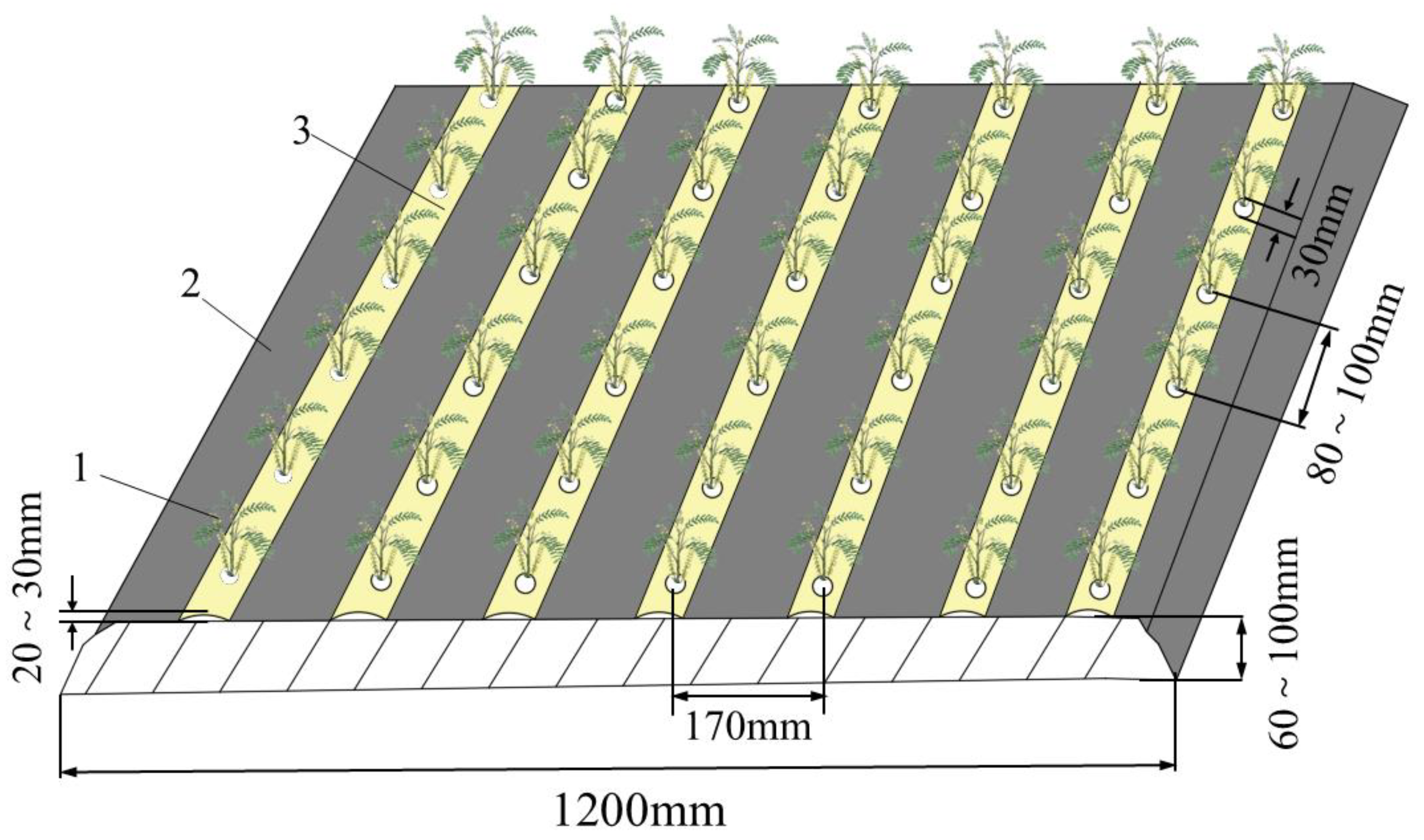
2.1.1. Agricultural Requirements for the Cultivation of Astragalus Film-Covered Outcrop

Astragalus is a perennial herbaceous plant with deep roots, suitable for growing in soil with deep soil layers, loose soil, and rich organic matter. Astragalus is usually planted from late March to mid-April. When transplanting, seedlings with a length of over 200 mm are selected and transplanted horizontally along the ditch. The planting depth of Astragalus is 50~80 mm, and the planting density is about 12,000~18,000 plants/hm2. The cultivation mode of Astragalus covered with mulch film is shown in Figure 1, with a ridge width of 1200 mm, a ridge height of 60~100 mm, a row spacing of 170 mm, and a seed row covering soil thickness of 20~30 mm. When transplanting Astragalus, a perforated plastic film with a width of 1400 mm and a thickness of 0.01 mm (with a hole diameter of 30 mm and a center distance of 100 mm between the two holes) should be used to cover the ridge and fine soil should be used to press down on both sides of the film. Finally, the planting holes on the film should be sealed by covering them in rows, without manual planting. This mode can prevent seedlings from burning, ensure the smooth emergence of Chinese medicinal seedlings, and has the advantages of drought resistance, moisture preservation, and weed growth inhibition.

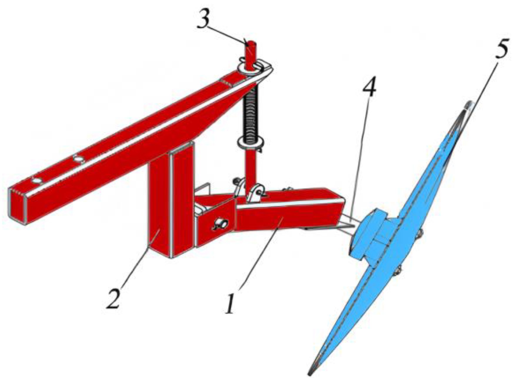
2.1.2. Structure and Main Technical Parameters of Astragalus Transplanter

The Astragalus mulching transplanting machine primarily consists of a frame, loosening shovels, trenchers, depth-limiting wheels, a shaping and suppressing device, seats, a mulching device, and a soil-covering device for the film. The structure is shown in Figure 2.
The transplanter is connected to the tractor via a suspension mechanism, which provides power to the transplanter. To meet the requirements for planting medicinal seedlings, the depth of the trencher can be adjusted using the central pull rod and depth-limiting wheel of the tractor. During the operation of the transplanting machine, the trencher, located beneath its suspension mechanism, cuts through the soil to create a seedbed. Concurrently, the planting personnel feed the seedlings through the feeding delivery port, allowing the medicinal seedlings to fall into the seedbed through the narrow gap formed between the feeding delivery port and the trencher wing plate, where they are laid flat in the direction of the machine’s advance. The wing plates on both sides of the trencher serve to prevent the collapse of the trench surface prior to the seedlings entering the seedbed, as well as to inhibit the backfilling of upper soil into the trench, which could affect the planting depth of the seedlings. Upon completion of seedling planting, the transplanting machine continues to advance, and the film-covering device lays the film over the formed seedbed, thereby completing the film-covering process. Finally, the soil-covering device executes the soil-covering operation along the edges and surface of the film.
The main technical parameters of the Astragalus mulching transplanting machine are shown in Table 1.

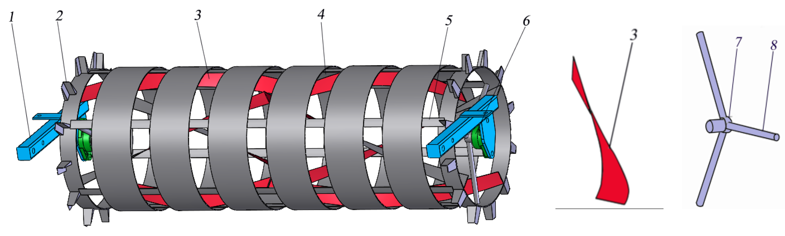
2.1.3. Structure and Working Principle of Soil-Covering Device

The soil-covering device of the Astragalus mulching transplanting machine mainly consists of the soil-covering disc and soil-covering drum assembly. Among them, the soil-covering disc assembly is shown in Figure 3. Two soil-covering discs are installed on both sides of the transplanting machine frame through a disc hanger, and their working angle and soil penetration depth can be adjusted. The soil-covering drum assembly is depicted in Figure 4. This soil-covering device is installed at the rear of the Astragalus transplanter and is powered by the traction mechanism located at the front of the transplanter. The soil-covering discs on either side of the frame are designed to cut into the soil, covering a portion of the soil at the edge of the mulch film to accomplish the edge-covering operation. Another portion of the soil is directed to the soil-covering drum, which rolls and rotates as the transplanter advances, driven by traction. As the soil-covering drum rolls along the ground, the soil entering the drum is transported to the excavation grooves by the frictional force exerted on the inner wall of the drum, aided by the belt-shaped spiral soil guide plate, as the inner wall of the drum rises. The number of excavation grooves corresponds to and overlaps with the number of transplanting rows. Once the soil is evenly released from the excavation grooves, it can be spread over the emergence holes of the mulch film, thereby completing the planting-row covering operation. Consequently, Astragalus seedlings can emerge from the reserved mulch film holes without the need for manual placement.

2.2. Design and Analysis of Soil-Covering Device

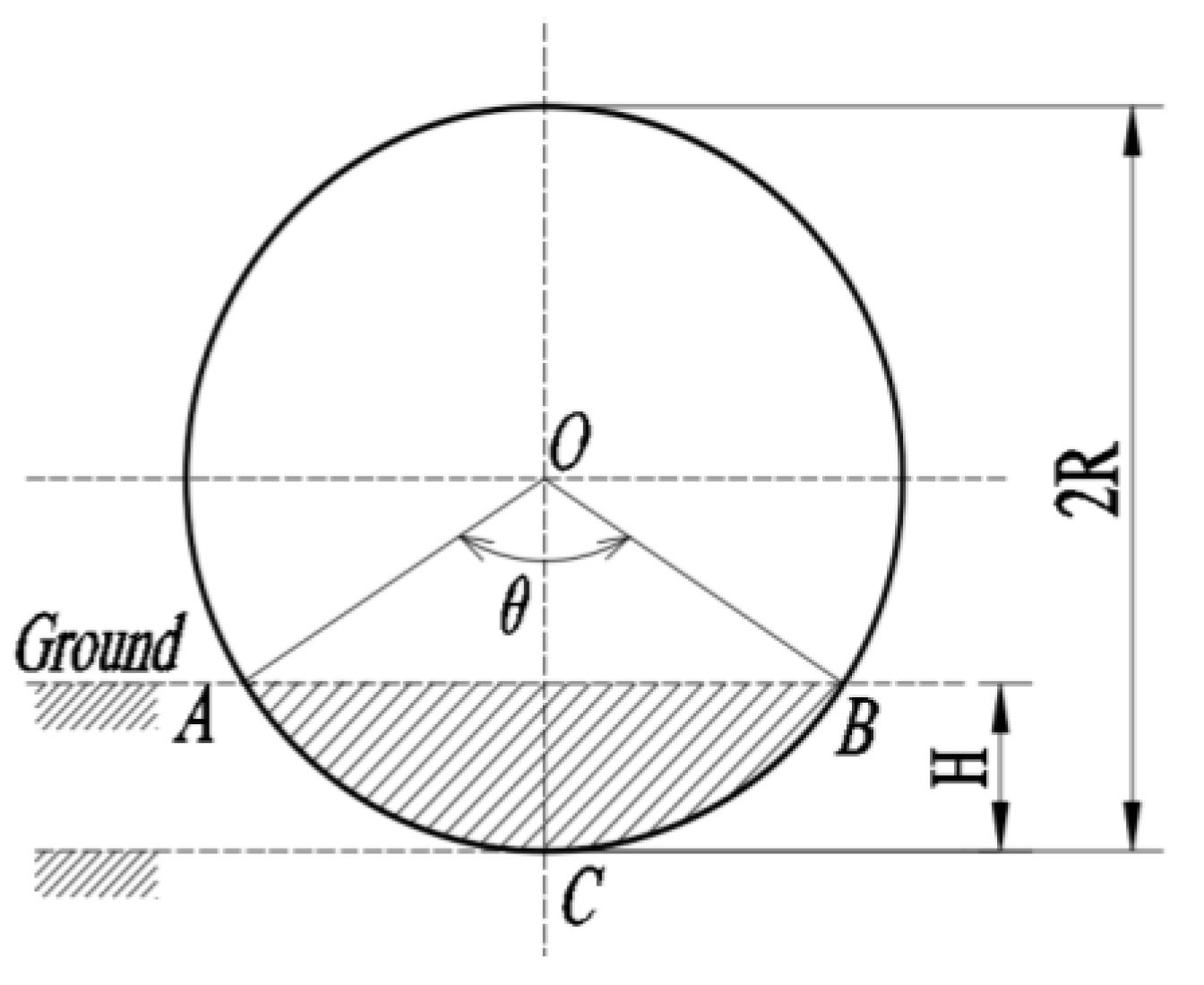
2.2.1. Design of Soil-Covering Disc

The soil-covering disc is a crucial component of the soil-covering device, significantly influencing the quantity of soil extracted by the device. When the amount of soil extracted is excessive, the excavation resistance of the disc increases, leading to higher power consumption and a higher likelihood of soil blockage in front of the soil-covering drum, which adversely affects the operational performance of the device. Conversely, if the amount of soil extracted is insufficient, it fails to meet the requirements for effective soil coverage, does not adequately compact the film, and struggles to resist natural wind forces that could displace the film, ultimately compromising its functionality. Therefore, it is essential to ensure adequate soil extraction during the operation while also managing excavation resistance to prevent it from becoming excessively high. To determine optimal operational parameters, mechanical analysis and theoretical calculations of the soil-covering disc are necessary.
(1)
Analysis of the circular disc soil extraction process
The process of covering the soil with a circular disc involves cutting into the soil section, as shown in Figure 5. Let AB be the intersection line between the ground and the disc; then there is
L = 2 R sin θ 2
θ = 2 cos 1 ( R H R )
S O A C B = θ π R 2 360
S Δ O A B = R ( R H ) sin θ
S = S O A C B S Δ O A B
Substituting Equations (2)–(4) into Equation (5) yields
S = π R 2 180 cos 1 R H R R R H sin cos 1 R H R
where L is the length of the intersection line AB between the disc and the soil, mm; R is the radius of the disc, mm; θ is the central angle,(°); H is the depth of soil sampling, mm; SOACB is the area of the sector corresponding to the central angle θ, mm2; SΔOAB is the area of ΔOAB, mm2; S is the soil sampling area of the covering disc, mm2.
Figure 5. Cross section of the soil-covering disc into the soil.
Agriculture 15 00769 g005
To avoid the phenomenon of missed sowing, the forward speed of the equipment should not be too fast. Generally, it moves at a low speed in crawling mode. The soil volume V taken by the covering disc per unit of time can be expressed as
V = S v = π R 2 v 180 × 10 6 cos 1 R H R R R H sin cos 1 R H R
where V represents the soil volume per unit time of a single covering disc, m3; v is the forward speed of the implement, m/s; S is the soil sampling area of the covered disc, mm2.
When the soil-covering disc is in operation, it becomes enveloped in soil due to the traction exerted by the transplanter. There exists a deviation angle α, between the end face of the disc and the Y-axis aligned with the forward direction of the transplanter, referred to as the disc deviation angle. The force analysis of the covering soil disc is illustrated in Figure 6, which highlights the primary influences on the disc: the cutting force exerted by the edge of the soil-covering disc on the soil, the pressure applied by the soil onto the disc, the frictional force between the soil and the covering soil disc, and the traction force generated by the transplanting machine. Given that the trencher located in front of the transplanting machine has already loosened the soil, the cutting force exerted by the covering soil disc on the soil is relatively minor and can be disregarded. Under normal operating conditions, the horizontal traction force in the forward direction of the unit must be no less than the resultant force acting on the soil-covering disc.
F q F y = F N y + F f y = F N sin α + F f cos α
F f = μ F N
F N = P S
where Fq is the horizontal traction force in the forward direction of the machine, N; Fy is the resultant force in the y-axis direction, N; FN is the pressure of the soil on the covering disc, N; Ff is the frictional resistance of the soil on the covering disc, N; FNy is the component of the pressure of the soil on the covering disc in the y-axis direction, N; Ffy is the component of the frictional resistance of the soil on the covering disc in the y-axis direction, N; α is the deflection angle of the covering disc, (°); μ is the friction coefficient of the soil on the covering disc; P is the soil stress intensity when taking soil from a covered disc, kPa.
From Equations (6) and (8)–(10), it can be concluded that
F q P sin α + μ cos α cos α π R 2 180 cos 1 R H R R R H sin cos 1 R H R
The analysis of the soil coverage by the disc and the associated stress reveals that the primary factors influencing the amount of soil covered include the operating speed (v), the radius of the disc (R), and the depth of disc extraction (H). Conversely, the main factors affecting the force exerted on the disc comprise the soil stress intensity (P), the soil friction coefficient (μ) against the disc, the disc radius (R), the disc deflection angle (α), and the disc extraction depth (H). Adjusting the values of these key factors can enhance the amount of soil collected; however, this also results in a corresponding increase in operational resistance. Consequently, the goal should be to optimize the amount of soil collected to meet operational requirements without excessively increasing it. According to the agronomic requirements for the cultivation of Astragalus film-covered outcrop, combined with the expression of the soil covering amount per unit time of the covering disc and the actual working conditions of the transplanting machine, the depth of the disc extraction is determined to be 80~100 mm.
(2)
Disk Structure Parameters
The quality of soil-covering disc operations is primarily influenced by several structural parameters, including the disc diameter, deflection angle, and inclination angle. The structural parameters can be calculated by referring to the empirical formula for the design of soil cover disks in reference [22], where the diameter D of the soil cover disk is
D = k H max
where D is the diameter of the disk, mm; k is the empirical coefficient; Hmax is the maximum plowing depth, mm.
Generally, the diameter-to-depth ratio of the disc is selected as 3.0~3.5 [23], taking into account that the soil extracted by the disc could not all enter the mulching drum, according to the results of the previous research and planting experience in order to increase the amount of soil taken, this study takes k = 3.5, and the maximum depth of soil taken Hmax = 100 mm can be obtained from Equation (12), D = 350 mm.
Furthermore, the thickness of the soil-covering disc should be judiciously selected based on the working load. This article employs empirical formulas to determine the thickness of the soil-covering disc, denoted as λ [24]
λ = 0.008 ~ 0.02 × D
Namely,
2.8 λ 7
Considering that the soil under the working conditions has been loosened by the trencher and the soil resistance experienced by the disc is relatively small, a thickness of λ = 5 mm that can withstand general working loads is selected.
Where D is the diameter of the disc, mm; λ is the thickness of the soil-covering disc, mm.
In summary, the high-strength steel 65 Mn, known for its wear resistance, corrosion resistance, and durability, has been selected as the material for the soil-covering disc. Based on existing research, the thickness of the disc has been determined to be 5 mm.
To ensure the cutting, crushing, and turning capabilities of the soil-covering disc, a deviation angle α is established between the soil-covering disc and the forward direction. As the angle α increases, both the area and volume of soil engaged by the disc rise, resulting in a corresponding increase in traction resistance. During operation, it is essential to raise a sufficient amount of soil for mulching while keeping the excavation resistance within manageable limits. Considering all factors, the selected range for the disc deviation angle for this machine is α = 25~45°.
In order to make the concave surface of the soil-covering disc facilitate the rise of the earth district during operation and enhance the ability to turn the district, the soil-covering disc and the plumb surface must have an inclination angle β, the value of which ranges from β = 15° to 25°, after field tests, the disc inclination angle of β = 15° was selected for the design of this machine, as shown in Figure 7 for the disc inclination, disc deflection schematic diagram.

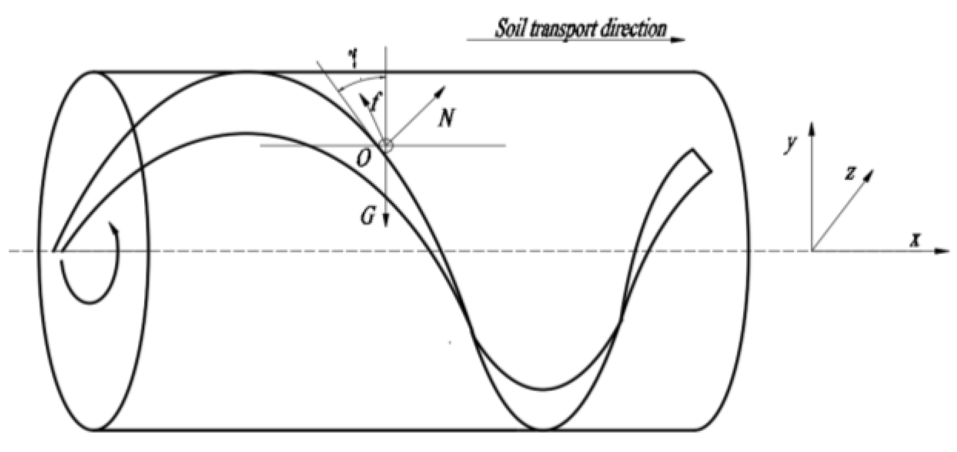
2.2.2. Design of Soil-Covering Drum

The soil-covering drum primarily receives soil from the soil-covering disc and transports it to cover the seedling holes on the mulch film. Its structural parameters significantly influence both the soil-conveying capacity and the operational performance of the soil-covering device.
(1)
Analysis of Soil Transport Model with Soil-Covering Drum
When the soil-covering drum rolls forward along the ground under the traction of the transplanting machine, the soil conveyed by the soil-taking disc enters the soil-covering drum. The soil rises on the inner wall of the drum and moves axially from both sides to the center under the guidance of the spiral soil guide plate. When it encounters the excavation groove, soil leakage occurs until it reaches the central excavation groove, thus achieving the planting and covering of soil on the film. When the soil roller rotates, soil particles undergo circumferential and axial movements under the action of the spiral blades, with circumferential movement being useless work and axial movement being useful work. Therefore, the axial movement distance of soil particles during the rotation of the drum should be increased as much as possible, and the circumferential movement distance should be reduced to increase the soil transport capacity and efficiency. To better analyze the motion process of soil particles on spiral blades, the spiral line of the diameter where soil particle O is located is unfolded, as shown in Figure 8. From the geometric relationship between different parameters shown in the figure, the cumulative distances of circumferential and axial motion of soil particle O can be obtained as follows:
L 1 = C sin γ sin γ + φ cos φ
L 2 = C sin γ cos γ + φ cos φ
of which t g γ = S / C ; C = π D , where L1 is the circumferential movement distance of soil particle O, m; L2 is the axial movement distance of soil particle O, m; C is the spiral circumference of point O on the spiral blade; D is the spiral diameter of point O on the spiral blade, m; γ is the helix angle,(°); φ is the friction angle between the soil and the spiral guide plate is denoted as (°), S is the pitch of the spiral, m.
If the angle at the lowest point of the spiral soil guide plate is 0°, then the angle range for transporting soil with each set of spiral soil guide plates is 0~90°. The direction of soil transport aligns with the positive direction of the x-axis. At point O on the strip spiral surface (where the spiral guide plate is positioned at 90°), the basic conditions for soil sliding along the spiral direction of the O-point section of the spiral guide plate are analyzed [25]. Based on Figure 9, an equation is established:
N = G sin γ f = N tan φ
where G is the combined force of the surrounding soil’s squeezing force and gravity along the circumference when the soil particles rotate with the drum, N; f is the frictional resistance when sliding in the direction of the spiral tangent at point O, N; N is the reactive force of the digging shovel on the soil, N.
In order to move the soil downwards along the spiral soil guide plate and successfully complete the planting and covering of soil, the following conditions must be met:
G cos > γ f
γ < π 2 φ
To ensure the smooth sliding of soil along the axial direction of the spiral soil guide plate, the helix angle γ at any point on the spiral guide plate must satisfy Equation (19). Taking into account factors such as surface roughness and soil moisture, we assume φ = 20° [26]. Consequently, the helix angle at any point on the spiral guide plate should be less than 70°. If the acceleration of the soil moving along the axial direction of the spiral soil guide plate is denoted as a, then the equation of motion for the soil is as follows.
m a = N cos γ f sin γ
where m is the soil mass, kg; a is the acceleration of the soil when it moves along the axial direction of the spiral soil guide plate, m/s2.
Combining (17) and (20), it can be concluded that
a = F 2 m sin 2 γ F m tan φ sin 2 γ
Ignoring other factors, we determine that axial soil transport is a function of the spiral soil guide plate angle γ. We analyze the effect of the angle γ of the spiral soil guide plate on the acceleration a. When a is at its maximum value, the corresponding γ represents the optimal angle of the spiral soil guide plate. Therefore, hence the derivation of γ for a. And ordered d a d γ = 0 . By finding its maximum value, the optimal angle γ can be obtained. Derive the gamma of Equation (21) a and find its maximum value, then
γ = π 4 φ 2
Substituting φ = 20° into Equation (22), the optimal angle γ = 35° is obtained, so the design value of the angle for the spiral soil guide plate is 35°.
(2)
Structural Parameters of Soil-Covering Drum
The diameter of the soil-covering drum significantly influences its soil transport capacity; the larger the diameter of the soil-covering drum, the stronger its ability to transport soil and the less likely it is to clog. However, excessively large drum sizes can increase the overall weight of the device, adversely affecting its longitudinal stability during suspension. For this, a smaller drum diameter can compromise soil transport capacity and increase the risk of clogging [27,28]. Consequently, based on prior research and preliminary experiments, the selected drum diameter for this design is 400 mm, with a length of 1420 mm. The drum suspension arm is constructed from 30 mm × 30 mm square tubes featuring a wall thickness of 3 mm. To facilitate the normal rotation of the drum, a half shaft and the bearings are symmetrically distributed on both sides. Furthermore, to ensure the structural integrity and roundness of the entire device, three spokes are installed on each side. These spokes are fabricated from ordinary carbon steel with a diameter of Φ10 and are welded to both the half shaft and cylindrical shell at their ends.
The spiral soil guide plate is essential for transporting and directing soil throughout the entire device, significantly influencing the quality of the soil covering the film. Its guiding efficiency is contingent upon the rotation direction and uniform distribution of the spiral soil guide plate. During the design phase, four groups were selected based on the principle of soil transportation from the exterior to the interior, utilizing 2 mm thick ordinary steel plates as the material. Soil is transported from both sides of the spiral soil guide plate to the center, with the quantity of soil decreasing at each excavation groove. Therefore, to ensure uniformity in soil coverage and to provide the requisite amount of soil for sealing the membrane hole, an appropriate excavation groove width must be designed. Field experiments revealed that the width of the excavation groove is symmetrically distributed from the outside to the inside, set at 40 mm, 45 mm, and 50 mm, respectively, with the width of the central excavation groove established at 60 mm.
From the theoretical analysis presented, it can be concluded that the structural parameters of the spiral soil guide plate are the primary research parameters when designing the soil cover drum. By integrating the soil transportation model, structural parameters such as the angle and number of columns of the spiral soil guide plate can be determined. Additionally, due to the complex accumulation effects of soil during actual transportation, a frictional interlocking phenomenon occurs between soil particles [29]. Therefore, when the soil-covering device of the Astragalus transplanting machine is operated in the field, the parameters of the soil-covering drum must be repeatedly adjusted and tested to achieve the desired moderate soil thickness and uniform soil coverage across various rows.

2.3. Test Materials

To verify the operational performance of the soil-covering device used in the Astragalus mulching transplanting machine and to determine the optimal working parameters, a field trial was conducted at the Northwest Research Base of Mechanization of the Whole Process of Chinese Medicinal Materials at Gansu Agricultural University in late March 2023. The soil in the experimental site is northwest yellow clay, which is flat, fine, and soft, without large soil blocks or stones. The soil solidity of the 0~50 mm soil layer is 80 kPa, the soil solidity of the 50~100 mm soil layer is 205 kPa, and the soil solidity of the 100~150 mm soil layer is 276 kPa. The soil moisture content of the 50~150 mm soil layer is 16.8%, and the soil bulk density of the 50~150 mm soil layer is 1230 kg/m³, which is suitable for mechanized transplanting. The field test site is shown in Figure 10. The experimental instruments and equipment included a Dongfanghong 454 tractor, the Astragalus mulching transplanting machine developed by the research group, a JC-JSD-03 soil firmness tester (Qingdao Juchuang Jiaheng, Qingdao, China, accuracy of ± 1%, resolution of 0.1 kPa), a Wike Mito VM-210S soil moisture meter (Jiangsu Wikert Instrumentation Co., Ltd., Taizhou, China, measuring range: 0 to 50%, resolution: 0.1%), a DT2234B photoelectric tachometer (Taiwan Luchang Electronic Enterprise Co., Ltd., Xinbei, Taiwan, range: 5~999.9 r/min, accuracy: ±0.05%), a high-precision electronic balance scale (accuracy: 0.001 g), a digital protractor (accuracy: ±0.2°), a steel ruler, a soil collection box, brushes, and other necessary tools.

2.4. Test Methods

The experiment referenced JB/T 10291-2013 “Dryland Planting Machinery”and NY/T 987-2006 “Laying Feeler Planter” [30,31]. The performance of the soil-covering device used in the Astragalus mulching transplanting machine was evaluated by the quantity of soil cover and the variation coefficient of soil cover quantity uniformity.

2.4.1. Quantity of Soil Cover (Q)

Start the tractor and operate the implements for a designated period. Once the operation stabilizes, conduct random sampling along the direction of the implements’ work over a 10 m long operating area. This area should be divided into five equal measurement sections, each measuring 1 m in length, with 1 m spacing between each section. In each measurement area, soil will be collected using a brush applied to the mainland membrane, where seven rows of soil will be swept into a soil collection box. Each row of soil will be weighed and labeled accordingly. The total weight of the seven rows of soil for each measurement area will be recorded, allowing for the calculation of the average soil quality for each section. Consequently, the amount of soil covered in a measurement area per meter can be determined as Q [32], in kg/m.

2.4.2. Variation Coefficient of Soil Cover Quantity Uniformity (QCV)

Upon completion of the experiment, the variation coefficient of soil cover quantity uniformity was calculated using Equation (23) [32], taking into account the soil quality of each seed row within the measurement area. The average variation coefficient of soil cover quantity uniformity was determined across the five measurement areas.
Q C V = i = 1 N m i m i ¯ 2 N 1 N i = 1 N m i × 100 %
where mi is the soil mass per row, m i ¯ is the average soil mass per row, kg; N is the number of soil rows.
Based on the results of prior analyses and the team’s previous research findings, we selected the disc extraction depth, disc deflection angle, and soil-covering drum rotation speed as the test factors. The quantity of soil cover and the variation coefficient of soil cover quantity uniformity were established as the test indices. We conducted a quadratic rotary orthogonal combination optimization test to validate the operational performance of the soil-covering device used in the Astragalus mulching transplanting machine and to explore the influence of operational parameters on the mulching indices, aiming to determine the optimal combination of these parameters. The encoded values for the depth of disc extraction, disc deflection angle, and rotation speed of the soil-covering drum are represented as X1, X2, and X3, respectively. The experimental factor encoding table is presented in Table 2. During the test, the deflection angle of the disc was modified by adjusting the angle-adjusting plate of the disc assembly, while the depth of the disc was regulated through the depth-limiting wheel and the suspension mechanism of the implements. In order to ensure the stability of the transplanting machine’s forward speed and the speed of the soil-covering drum, a deceleration mechanism and drum suspension arm are used for adjustment. During the experiment, when the tractor and transplanter are running smoothly in a flat terrain area, adjust the tractor throttle and gear and use the DT2234B photoelectric tachometer to measure the speed of the soil roller. When the required value is reached, move forward at a constant speed of 1 m and measure the experimental data.

2.5. Test Results

According to the Box–Behnken test principle, a total of 17 sets of experiments were conducted. This includes 12 analysis factors and 5 zero-point estimation errors. The results of the evaluation indicators for the quantity of soil cover (Q) and variation coefficient of soil cover quantity uniformity (QCV) in each experimental scheme and its model are shown in Table 3.

3. Results and Discussion

Multiple linear regression fitting and analysis of variance were performed on the experimental data, and the results are shown in Table 4. The models for soil cover quantity (Q) and variation coefficient of soil cover quantity uniformity (QCV) were highly significant (p < 0.001 for the model), and the out-of-fit term was not significant (p > 0.05 for the out-of-fit term). It is shown that the structural working parameters of the soil-covering device of the Astragalus mulching transplanting machine can be analyzed and optimized by this model.

3.1. Regression Model Establishment and Significance Analysis

3.1.1. Significance Analysis of the Quantity of Soil Cover

The significance of the effect of each regression term on the regression model is usually determined by the magnitude of the p-value [33]. Through the analysis of experimental data, the variance analysis of soil cover quantity Q is shown in Table 4. As can be seen from Table 4, for the test indicator soil cover quantity Q, the main order of influence of factors and interactions between factors were X 2 2 , X2, X1, X 1 2 , X1X2, X3, X2X3, X 3 2 , X1X3; The effect of X1, X2, X3, X1X2, X 1 2 , and X 2 2 on soil cover quantity Q was highly significant (p < 0.01); The effect of X2X3 on soil cover quantity Q was significant (0.01 < p < 0.05); The effect of X 3 2 and X1X3 on soil cover quantity Q was not significant (p > 0.01). On the basis of ensuring that the model is significant and the out-of-fit term is not significant, the insignificant regression term in the model is eliminated, the Q model of soil cover quantity is optimized and organized [34], and the regression equation between factors and indicators is obtained, as shown in Equation (24).
Q = 10.26 + 0.6513 X 1 + 0.6875 X 2 + 0.4387 X 3 + 0.6600 X 1 X 2 + 0.2550 X 2 X 3 0.7803 X 1 2 1.49 X 2 2

3.1.2. Significance Analysis of the Variation Coefficient of Soil Cover Quantity Uniformity

According to Table 4, for the variation coefficient of soil cover quantity uniformity, the primary and secondary order of the interaction effects between factors is as follows: X1X2, X 1 2 , X 3 2 , X 2 2 , X1X3, X2X3, X3, X1, and X2. The effect of X 1 2 , X 2 2 , X 3 2 , X1X2, X1X3, and X2X3 on the variation coefficient of soil cover quantity uniformity was highly significant (p < 0.01). The effect of X1, X2, and X3 on the variation coefficient of soil cover quantity uniformity was significant (0.01 < p < 0.05). The model of the variation coefficient of soil cover quantity uniformity was optimized and organized to obtain the regression equation between factors and indicators, as shown in Equation (25).
Q C V = 2.21 0.5850 X 1 0.5113 X 2 0.5888 X 3 4.05 X 1 X 2 + 1.63 X 1 X 3 + 1.02 X 2 X 3 + 2.78 X 1 2 + 2.19 X 2 2 + 2.32 X 3 2

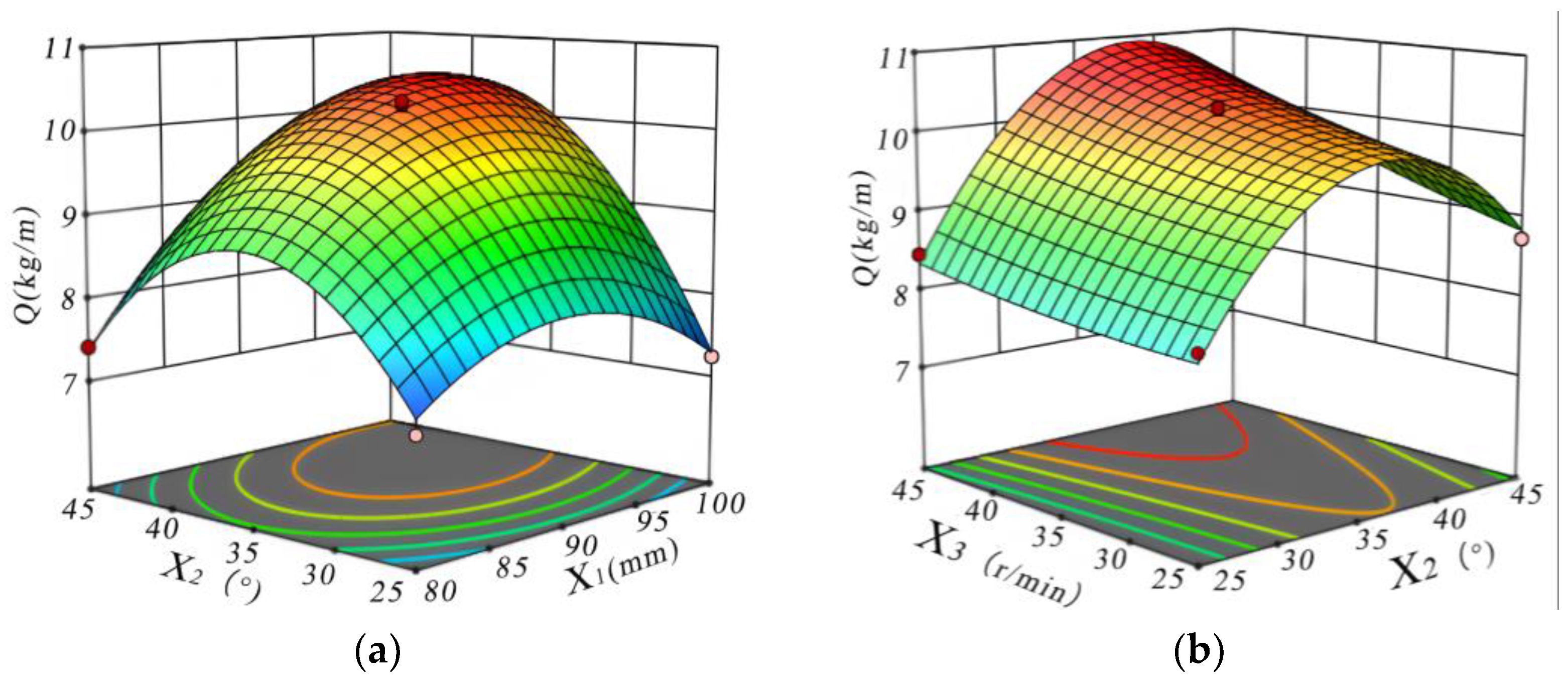
3.2. Response Surface Analysis

Based on the regression equation and the results of the significance analysis, the data were processed using Design-Expert 12 software to derive the response surfaces for the more significant interactions among disc extraction depth (X1), disc deflection angle (X2), and soil-covering drum rotation speed (X3). These interactions affect the two experimental metrics: the quantity of soil cover (Q) and the variation coefficient of soil cover quantity uniformity (QCV), as illustrated in Figure 11 and Figure 12.

3.2.1. Analysis of the Effect Pattern of Interaction Factors on the Quantity of Soil Cover

As shown in Figure 11a, when the rotation speed of the soil-covering drum is 30 r/min, the quantity of soil cover shows a trend of first increasing and then decreasing with the increase in the disc extraction depth and disc deflection angle, among which the influence of the disc deflection angle on the quantity of soil cover is more significant. When the deflection Angle of the disk is constant, the quantity of soil cover first gradually increases and then slowly decreases with the increase in the depth of the disk extraction, and the depth of the disk extraction is increased, the quantity of soil cover gradually increases, but the power required by the disk operation is obviously increased, the relative change in soil flow movement is not obvious, and the quantity of soil cover decreases. Conversely, when the disc extraction depth is kept constant, an increase in the disc deflection angle causes the quantity of soil cover to first rise and then fall. As the disc deflection angle increases, the resistance encountered by the disc also rises, which initially boosts the quantity of soil cover but eventually leads to a significant reduction in it. Overall, a higher disc deflection angle correlates with a marked increase in disc resistance, contributing to a gradual decrease in the quantity of soil cover.
As shown in Figure 11b, when the depth of the disc extraction is 90 mm, the quantity of soil cover initially increases with increasing disc deflection, reaches a peak, and then decreases. Simultaneously, the rotation speed of the soil-covering drum experiences a gradual increase. Notably, the disc deflection has a more pronounced effect on the quantity of soil cover. When the rotation speed of the soil-covering drum is held constant, the quantity of soil cover increases with the disc deflection angle up to a certain point, after which it decreases. This trend indicates that as the disc deflection angle increases, the resistance of the disc also rises significantly, leading to a gradual reduction in the quantity of soil cover. Conversely, when the disc deflection angle is fixed, an increase in the rotation speed of the soil-covering drum results in a slow increase in the quantity of soil cover, suggesting that the rotation speed has a lesser impact on the quantity of soil cover.

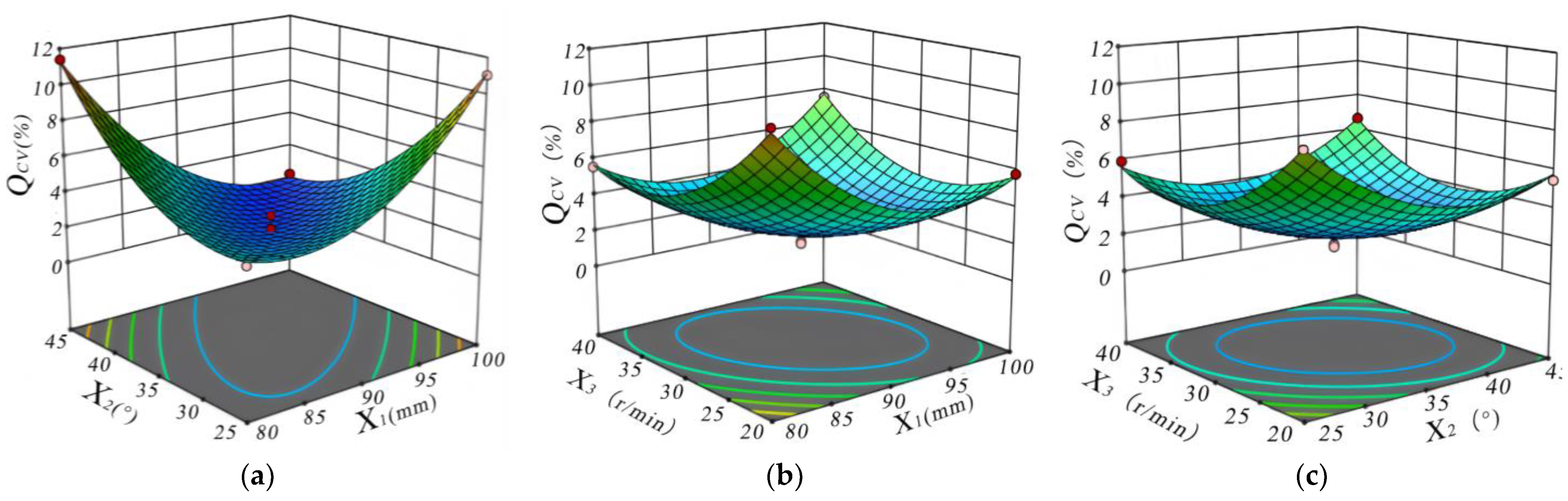
3.2.2. Analysis of the Pattern of Interaction Factors on the Variation Coefficient of Soil Cover Quantity Uniformity

As shown in Figure 12a, at a rotational speed of 30 r/min for the soil-covering drum, the variation coefficient of soil cover quantity uniformity exhibits an upward trend as both the depth of disc extraction and the disc deflection angle increase. Notably, the impact of depth of disc extraction on the variation coefficient of soil cover quantity uniformity is more pronounced. When the disc deflection angle is held constant, an increase in disc extraction depth leads to greater forward resistance of the disc, making it challenging to create a continuous and uniform mulching belt; consequently, the variation coefficient of soil cover quantity uniformity rises. Conversely, when the depth of disc extraction is constant, an increase in disc deflection angle causes soil to accumulate between the disc and the soil-covering drum, which results in an increase in covering soil and a subsequent decrease in the variation coefficient of soil cover quantity uniformity.
As shown in Figure 12b, when the deflection angle of the disc is set at 35°, the variation coefficient of soil cover quantity uniformity of the overburden amount initially decreases and then gradually increases as the depth of the disc extraction and the rotational speed of the soil-covering drum increase. Notably, the depth of disc extraction has a more pronounced effect on the variation coefficient of soil cover quantity uniformity of the overburden amount. When the rotational speed of the soil-covering drum is fixed, the variation coefficient of soil cover quantity uniformity decreases steadily before experiencing a slight increase with the increasing depth of disc extraction. Conversely, when the depth of disc extraction is held constant, the variation coefficient of soil cover quantity uniformity first increases and then decreases as the rotational speed of the soil-covering drum rises. Higher rotational speeds of the soil-covering drum result in increased soil flow rates, which complicates the formation of a uniform mulch zone.
As shown in Figure 12c, when the depth of disc extraction is 90 mm, the variation coefficient of soil cover quantity uniformity initially decreases and then gradually increases with the rise in both the disc deflection angle and the rotational speed of the soil-covering drum. Notably, the rotational speed of the soil-covering drum exerts a more pronounced influence on the variation coefficient of soil cover quantity uniformity. When the disc deflection angle is held constant, the variation coefficient of soil cover quantity uniformity decreases and subsequently increases with the increase in soil-covering drum speed. Conversely, when the soil-covering drum speed is fixed, the variation coefficient of soil cover quantity uniformity increases and then decreases as the disc deflection angle increases. An optimal combination of soil-covering drum rotational speed and disc deflection angle can effectively prevent soil accumulation while also minimizing the forward resistance of the machine.

3.3. Parameter Optimization

Based on the analysis of the above experimental results, in order to obtain the optimal motion and structural parameters for the soil-covering device of the Astragalus mulching transplanting machine, the optimization module of Design-Expert 12 software was used to optimize the regression model with constrained objectives. In response to the drought and strong winds in the arid northwest region of China, the soil moisture on the plastic film is quickly lost and easily blown away by the wind, which can lead to a sharp decrease in the amount of soil cover. Without affecting seedling emergence, the amount of soil cover should be increased to achieve a better compaction effect. Therefore, this study takes the maximum soil cover amount and the minimum coefficient of variation in soil cover uniformity as the optimization objectives. Under the constraints of various experimental factors, a parameter optimization model is established to analyze the regression equation. The mathematical model obtained is
max Q ( X 1 , X 2 , X 3 ) min Q C V ( X 1 , X 2 , X 3 ) s . t . 80   m m X 1 100   m m 25 ° X 2 45 ° 20 r / min X 3 40 r / min
Through the optimization solution, it is obtained that when the depth of disc excavation is 94.91 mm, the deflection angle of disc is 39.67°, and the rotation speed of soil-covering drum is 29.88 r/min, the quantity of soil cover and variation coefficient of soil cover quantity uniformity are 10.53 kg/m and 1.89%, respectively, and the soil-covering device of Astragalus mulching transplanting machine has the optimal performance.

3.4. Field Validation Test

To verify the accuracy of the model’s prediction results, a field validation test was conducted in early April 2024 at the same experimental site. The validation results are presented in Figure 13. The optimized parameters used for the validation test were rounded as follows: the depth of disc extraction was set to 95 mm, the deflection angle of the disc was 40°, and the rotation speed of the soil-covering drum was maintained at 30 r/min. The test was repeated five times to obtain an average value, and the optimized test results are summarized in Table 5.
As evidenced by the test results presented in Table 5, the optimization of the operating parameters of the soil-covering device in the Astragalus mulching transplanting machine led to an increase in the average soil cover quantity by 0.08 kg/m compared to the pre-optimization state. Additionally, the average variation coefficient of soil cover quantity uniformity decreased by 0.1% following optimization. These findings indicate that the optimized parameter combinations for the soil-covering device are both reasonable and effective. This study’s results can serve as a valuable reference for the structural enhancement of the soil-covering device and the management of operating parameters in Astragalus mulching transplanting machines.

4. Conclusions

(1) Addressing the challenges associated with manual seedling release, such as the tendency for the mulch layer to slough off and the risk of film exposure during high winds in the process of Astragalus mulching transplantation, a soil-covering device for the Astragalus mulching transplanting machine has been designed in accordance with the agronomic requirements of both mulching and outcrop cultivation. This device facilitates row mulching and significantly enhances the level of mechanized mulching transplantation for Astragalus. Through theoretical analysis and calculations, the structure and operational parameters of the key components have been established: the diameter of the soil extraction disk is 350 mm, with an inclination angle (β) of 15° and a deflection angle (α) ranging from 25° to 45°; the soil-covering drum measures 1420 mm in length and 400 mm in diameter, with a helix angle of the spiral guide plate set at 35°.
(2) Based on the analysis of the soil-covering device’s disc extraction operation process and the soil-covering drum soil transport model, the primary factors influencing the performance of the soil-covering device were identified. The response surface method was employed to examine the impact of various factors on the operational quality of the soil-covering device used in the Astragalus mulching transplanting machine. It was concluded that the main factors affecting the quantity of soil cover, ranked by importance, are as follows: disc deflection angle, disc extraction depth, and soil-covering drum rotation speed. Additionally, the key factors affecting the variation coefficient of soil cover quantity uniformity of overburden are ranked in order of importance as follows: the rotation speed of the soil cover drum, the depth of the disc extraction, and the deflection Angle of the disc. The main factors affecting the variation coefficient of soil cover quantity uniformity, in order of importance, are the rotation speed of the soil cover drum, the depth of the disc extraction, and the disc deflection angle.
(3) The Box–Behnken response surface method was employed to analyze the effects of disc soil extraction depth, disc deflection angle, and soil-covering drum rotation speed on the quantity of soil cover and variation coefficient of soil cover quantity uniformity. A regression model was established between various factors and indicators. Through optimization analysis and field verification experiments, when the disc extraction depth was 95 mm, the disc deflection angle was 40°, and the soil-covering drum rotation speed was 30 r/min, the quantity of soil cover and variation coefficient of soil cover quantity uniformity were 10.61 kg/m and 1.79%, respectively. The results of the experimental verification were consistent with the theoretical predictions. Under the optimal working parameters, the soil-covering device significantly enhanced the operational performance of the Astragalus mulching transplanter and fulfilled the agronomic requirements for Astragalus mulching and outcrop cultivation.

Author Contributions

Conceptualization, B.F. and W.S.; methodology, J.W.; experiment, G.W. and S.X.; data curation, G.W.; writing—original draft preparation, B.F. and J.W.; writing—review and editing, W.L. and W.S. All authors have read and agreed to the published version of the manuscript.

Funding

This research was funded by the Talent Project of Gansu Agricultural University (GAU-KYQD-2020-33), the Gansu Province Science and Technology Plan Project (23CXNA0007), Gansu Province Agricultural Machinery Equipment R&D Key Project (njyf2024-03-1), the Key Scientific and Technological Program of Gansu Province (22ZD6NA046), and the Lanzhou Youth Science and Technology Talent Innovation Project (2023-QN-26).

Institutional Review Board Statement

Not applicable.

Data Availability Statement

Data are reported within the article.

Conflicts of Interest

The authors declare no conflict of interest.

References

  1. Li, B.; Geng, G. Research Progress on the Chemical Composition and Pharmacological Effects of Astragalus. Chin. W. Med. Res. 2022, 14, 262–264. [Google Scholar]
  2. Hu, J. Comparative Experiment on Seedling Raising with Different Sowing Amounts of Astragalus Seeds. Agric. Sci. Technol. Inf. 2020, 5, 20–21. [Google Scholar]
  3. Zhao, J.; Wang, Y.; Wang, Y.; Deng, A.; Nan, T.; Kang, L.; Zhan, Z. Comparative Study of Transplanted and Wild-Simulated Astragalus Based on Traditional Quality Evaluation. Chin. Exp. Formul. J. 2024, 30, 21–30. [Google Scholar]
  4. Gao, S.; Li, K.; Qin, X.; Li, Z.; Li, A.; Liu, Y.; Du, G.; Zhang, X. Comparative Study on the Quality of Wild and Transplanted Astragalus Based on Absolute Growth Age. Chin. Herb. Med. 2018, 49, 2248–2257. [Google Scholar]
  5. Cao, Z.; Sun, X.; Pan, F.; Li, R.; Wu, Y.; Li, Z.; Wang, L.; Huang, X. Effect of Transplantation Methods on the Growth and Yield of a New Variety of Astragalus, Xiqi No. 1. Gansu Agric. Sci. Technol. 2021, 52, 58–60. [Google Scholar]
  6. Li, W.; Tang, X.; Wang, C. Standardized, High-Quality, and Efficient Cultivation Techniques for Astragalus. Agric. Technol. Equip. 2023, 3, 182–184. [Google Scholar]
  7. Chen, X.; Lü, Z.; Xue, X.; Xin, L.; Yu, Q.; Yu, Y.; Zhao, Y. Development and Performance Experiment of Wireless Remote Control Walking Rice Transplanter. Trans. Chin. Soc. Agric. Eng. 2017, 33, 10–17. [Google Scholar]
  8. Khadatkar, A.; Mathur, S.M. Design and Development of an Automatic Vegetable Transplanter Using a Novel Rotating Finger Device with Push-Type Mechanism for Plug Seedlings. Int. J. Veg. Sci. 2022, 28, 121–131. [Google Scholar] [CrossRef]
  9. Ramirez-Castro, E.; Shkiliova, L. Technological and Operational Evaluation of Agricultural Units in Mechanized Tobacco Cultivation. Rev. Cienc. Técnicas Agropecu. 2021, 30, 33–45. [Google Scholar]
  10. Xu, G.; Liu, H.; Jian, S.; Shi, C.; He, T. Design and Experiment of a Five-Bar Mechanism for the Transplantation of Salvia miltiorrhiza on Film. Trans. Chin. Soc. Agric. Eng. 2018, 49, 55–65. [Google Scholar]
  11. Lu, D. Design and Experimental Research on Seedling Placement Device of American Ginseng Transplanting Machine. Master’s Thesis, Jilin Agricultural University, Changchun, China, 2022. [Google Scholar]
  12. Sun, W. Design and Experiment of a Directional Transplanting Device for Panax Notoginseng Seedlings Based on Object Detection. Master’s Thesis, Kunming University of Science and Technology, Kunming, China, 2023. [Google Scholar]
  13. Ma, X.; Zhang, L.; Liu, P.; Li, S. Design and Field Testing of a Combined Film Mulching and Soil Covering Machine for Dangshen Cultivation. Agric. Mech. Res. 2024, 46, 82–88. [Google Scholar]
  14. Liu, K.; Lin, Z.; Cai, L. Design and Study of a Dense Planting Transplanting Machine for Ophiopogon japonicus. Agric. Technol. Equip. 2024, 2, 1–4+7. [Google Scholar]
  15. Zuo, S.; Ding, X.; Kong, D.; Liu, Q.; Zuo, S. Design and Experiment of a Fully Automatic Ginseng Transplanting Machine. Agric. Mechanization Res. 2025, 47, 127–132. [Google Scholar]
  16. Xiao, X.; Wang, X.; Zeng, L.; Yang, Y. Effect of Plastic Film Mulching on the Cultivation of Chinese Medicinal Materials. Spec. Econ. Anim. Plants 2024, 27, 166–171+175. [Google Scholar]
  17. Shen, L.; Chen, W.; Teng, S.; Gu, X. Design and Testing of Key Components of a Slot-Wheel Astragalus Transplanting Machine. Chin. J. Agric. Mech. Chem. 2024, 45, 71–78. [Google Scholar]
  18. Li, S.; Ma, X.; Zhang, L.; Liu, P. Design and Experiment of Ridge Raising, Film Covering, and Soil Covering Transplanting Machine for Rhizome Chinese Medicinal Materials. J. Agric. Mech. Res. 2025, pp. 1–8, (Online debut version). Available online: http://kns.cnki.net/kcms/detail/23.1233.S.20250116.1312.004.html (accessed on 30 March 2025).
  19. Bai, Y. Design and Performance Testing of an Integrated Machine for Transplanting Astragalus with Film and Drip Irrigation. Master’s Thesis, Inner Mongolia Agricultural University, Hohhot, China, 2023. [Google Scholar]
  20. Wang, Y.; Zheng, S.; Kang, Q.; Zhao, J.; Liu, P. Design and experiment of a combined operation machine for mulching, fertilization, and transplanting of Codonopsis pilosula. Agric. Mech. Res. 2025, 47, 192–196. [Google Scholar]
  21. Zhu, P.; Cao, X.; Li, X.; Zhang, F.; Liu, P.; Zhang, L. Design and Experiment of a Seedling Transplanting Machine for Astragalus with Ridging and Mulching. Agric. Mech. Res. 2024, 46, 83–89. [Google Scholar]
  22. Liu, F.; Gao, X.; Jia, X.; Huang, Y.; Zhang, C. Design and Test of Archimedean Spiral Curved Double tooth Disc Soil Covering Device for High speed Precision Seeding Machine. J. Agric. Mach. 2024, 55, 91–100+120. [Google Scholar]
  23. Lü, J.; Zhang, X.; Zhu, X.; Li, J.; Yang, D.; Sun, Q. Design and Testing of Key Components for a Large-Row Double-Line Potato Mulching Machine. J. Northeast Agric. Univ. 2023, 54, 88–96. [Google Scholar]
  24. Li, H. Research on Rice Plastic Film Mulching Dry Direct Seeding Technology and Equipment. Master’s Thesis, Jilin University, Changchun, China, 2021. [Google Scholar]
  25. Wang, J.; Liu, X.; Han, M.; Hou, H.; Liu, F. Optimization Design of a Double-Disc Soil-Covering Device. Chin. J. Agric. Mech. Chem. 2016, 37, 37–39. [Google Scholar]
  26. Mei, Z.; Li, H.; Qi, X.; Hu, T.; Li, C. Testing and Analysis of the Mechanical Properties of Sandy Soil. J. Shenyang Agric. Univ. 2018, 49, 605–612. [Google Scholar]
  27. Zhang, X.; Li, Y.; Yang, J. Parameter Optimization and Analysis of the Seed-Covering Drum of a Sowing Machine Based on Discrete Element Method. Chin. J. Agric. Mech. Chem. 2020, 41, 43–48. [Google Scholar]
  28. Fan, Y.; Yang, R.; Chai, H.; Guo, T. Design and Experimental Research on a Film Mulching Device for Seedling Transplanting. Chin. J. Agric. Mech. Chem. 2014, 35, 5–8. [Google Scholar]
  29. Zhao, J.; Zhao, W.; Tian, S.; Zhang, Q.; Song, J.; Li, Y.; Han, X. Simulation and Experimental Study of the Soil-Covering Component for Fritillaria. Agric. Mech. Res. 2023, 45, 24–31. [Google Scholar]
  30. JB/T 10291-2013; Dryland Planting Machinery. Ministry of Industry and Information Technology of the People’s Republic of China Machinery Industry Press: Beijing, China, 2014.
  31. NY/T 987-2006; Quality of Film Mulching Hole-Seeding Machines. Ministry of Agriculture and Rural Affairs of the People’s Republic of China. China Agricultural Press: Beijing, China, 2006.
  32. Wang, Y. Experimental Study and Parameter Optimization of Soil Compaction Device for Cotton Seeder. Master’s Thesis, Shihezi University, Shihezi, China, 2023. [Google Scholar]
  33. He, W.; Xue, W.; Tang, B. Optimization Experimental Design Methods and Data Processing; Chemical Industry Press: Beijing, China, 2012. [Google Scholar]
  34. Ge, Y.; Liang, Q.; Wang, G. Experimental Design Methods and the Application of Design-Expert Software; Harbin Institute of Technology Press: Harbin, China, 2015. [Google Scholar]
Figure 1. Cultivation mode of Astragalus outcrop: 1. Astragalus seedling; 2. Mulch film; 3. Covering soil on seedling row.
Agriculture 15 00769 g001
Figure 2. Structural diagram of Astragalus mulching transplanting machine: 1. Frame; 2. Loosening shovel; 3. Trencher; 4. Limit deep wheel; 5. Shaping and suppressing device; 6. Film-covering device; 7. Soil-covering disc; 8. Soil-covering drum; 9. Seedling delivery port; 10. Seat.
Agriculture 15 00769 g002
Figure 3. Soil-covering disc assembly: 1. Connecting pipes; 2. Disc hanger; 3. Tightening spring and guide rod; 4. Angle adjustment plate; 5. Soil-covering disc.
Agriculture 15 00769 g003
Figure 4. Soil-covering drum assembly: 1. Drum suspension arm; 2. Penetration gear teeth; 3. Spiral soil guide plate; 4. Excavation grooves; 5. Support rib; 6. Bearings; 7. Half axis; 8. Spokes.
Agriculture 15 00769 g004
Figure 6. Force analysis diagram of soil-covering disc.
Agriculture 15 00769 g006
Figure 7. Schematic diagram of disk inclination and deflection angle.
Agriculture 15 00769 g007
Figure 8. Spiral unfolding diagram of soil particles at point O.
Agriculture 15 00769 g008
Figure 9. Force analysis of soil on the spiral batten.
Agriculture 15 00769 g009
Figure 10. Field test.
Agriculture 15 00769 g010
Figure 11. Response surface of each factor to the cover soil quantity (Q): (a) Excavation depth (X1) and Disk deflection angle (X2); (b) Disc deflection angle (X2) and Soil-covering drum speed (X3).
Agriculture 15 00769 g011
Figure 12. Response surface of each factor to the variation coefficient of soil cover quantity uniformity (QCV): (a) Excavation depth (X1) and disk deflection Angle (X2); (b) Excavation depth (X1) and Soil-covering drum speed (X3); (c) Disc deflection angle (X2) and Soil-covering drum speed (X3).
Agriculture 15 00769 g012
Figure 13. Astragalus soil covering operation and seedling emergence effect.
Agriculture 15 00769 g013
Table 1. Main technical parameters.
ItemParameter
Machine dimensions (length × width × height)/mm2450 × 1565 × 1080
Machine weight/kg160
Power/kW29.42~51.48
Machine forward speed/(km/h)1.8~2.1
suspension modethree-point suspension
Machine working width/mm1400
Transplanting depth/mm50~150
Number of rows transplanted/(rows)7
Row spacing/mm170
Plastic film width/mm1400
Thickness of plastic film/mm0.01
Thickness of soil cover for planting/mm20~50
Working efficiency/(hm2/h)0.13~0.15
Table 2. Coding of test factors.
CodeDepth of Disc Extraction
X1 (mm)
Disc Deflection Angle
X2 (°)
Rotation Speed of Soil-Covering Drum
X3 (r/min)
−1802520
0903530
11004540
Table 3. Test plan and results.
TestX1X2X3Quantity of Soil Cover Q (kg/m)Variation Coefficient of Soil Cover Quantity Uniformity
QCV (%)
10−118.455.93
201110.116.66
3−10−18.4710.32
4−1107.4111.40
500010.331.65
6−1−107.134.04
701−18.735.46
800010.052.29
900010.241.76
1011010.162.23
1100010.312.32
120−1−18.098.82
13−1019.475.56
141−107.2411.05
1510110.537.55
1610−19.765.81
1700010.363.04
Table 4. Analysis of variance of soil cover quantity.
SourceQuantity of Soil Cover Q (kg/m)Variation Coefficient of Soil Cover Quantity Uniformity QCV (%)
Sum of SquaredfF-Valuep-ValueSum of SquaredfF-Valuep-Value
Model23.24992.32<0.0001 **171.84981.90<0.0001 **
X13.391121.33<0.0001 **2.74111.740.0110 *
X23.781135.21<0.0001 **2.0918.970.0201 *
X31.54155.070.00012.77111.890.0107 *
X1X21.74162.31<0.0001 **65.451280.74<0.0001 **
X1X30.013210.47290.513810.56145.310.0003 **
X2X30.260119.300.01864.18117.940.0039 **
X 1 2 2.56191.66<0.0001 **32.551139.61<0.0001 **
X 2 2 9.381335.50<0.0001 **20.15186.44<0.0001 **
X 3 2 0.026810.95760.360422.62197.02<0.0001 **
Residual0.19587 1.637
Lack of fit0.133932.880.16630.408430.44510.7340
Pure error0.06194 1.224
Total23.4316 173.4716
Note: * indicates significant, ** Indicating extremely significant.
Table 5. Comparison of test results before and after optimization.
ItemDepth of Disc Extraction
X1 (mm)
Disc Deflection Angle
X2 (°)
Rotation Speed of Soil-Covering Drum X3 (r/min)QCV/%Q/kg/m
Before optimization94.9139.6729.881.8910.53
After optimization9540301.7910.61
Disclaimer/Publisher’s Note: The statements, opinions and data contained in all publications are solely those of the individual author(s) and contributor(s) and not of MDPI and/or the editor(s). MDPI and/or the editor(s) disclaim responsibility for any injury to people or property resulting from any ideas, methods, instructions or products referred to in the content.

