Article

Path Tracking Control of a Large Rear-Wheel–Steered Combine Harvester Using Feedforward PID and Look-Ahead Ackermann Algorithms

1
School of Agricultural Engineering, Jiangsu University, Zhenjiang 212013, China
2
Key Laboratory for Theory and Technology of Intelligent Agricultural Machinery and Equipment of Jiangsu University, Zhenjiang 212013, China
*
Author to whom correspondence should be addressed.
Agriculture 2025, 15(7), 676; https://doi.org/10.3390/agriculture15070676
Submission received: 5 March 2025 / Revised: 19 March 2025 / Accepted: 20 March 2025 / Published: 22 March 2025
(This article belongs to the Section Agricultural Technology)

Abstract

:
Autonomous driving solutions for agricultural machinery have advanced rapidly; however, large-wheeled harvesters present unique challenges compared to traditional vehicles. Specifically, the 5.4 m cutting width, 9.2 m minimum turning diameter, and rear-wheel–steered configuration demand specialized path tracking and steering methods. To address these challenges, this study developed an integrated system combining feedforward PID and Look-Ahead Ackermann (LAA) algorithms with sensors, actuators, and an embedded control platform. Field experiments indicated that the system maintained an average lateral deviation of approximately 5 cm on straight-line paths, with slightly larger errors observed only during turning or alignment maneuvers. Additionally, a “three-cut” steering method was implemented, which enhanced path tracking accuracy and prevented crop damage at headland turns. Successful field tests confirmed the robustness of the developed system, highlighting its practical potential for production-level autonomous harvesting.

1. Introduction

With the rapid development of satellite navigation and autonomous driving technologies, the automation level of agricultural machinery, especially combine harvesters, has significantly advanced [1,2]. While there are similarities between wheeled agricultural machines and traditional vehicles in terms of kinematics, dynamics, and GPS-based positioning, agricultural machines operate in fields with complex terrain and crop layouts, presenting unique challenges [3,4,5]. Agricultural vehicles typically travel at lower speeds and are not constrained by traffic regulations, which allows simpler control algorithm designs [6]. However, the variability in field conditions, crop arrangements, and the need for high-precision path tracking in agricultural machinery operations demand more sophisticated control systems [7].
Early research in agricultural machinery path tracking control primarily focused on developing basic kinematic models and control algorithms [8,9,10]. For instance, Ding et al. improved path tracking precision by applying a single-layer neural network and a PID control algorithm for wheeled combine harvesters, achieving an average lateral deviation of 0.032 m at 0.7 m/s in field conditions [11]. Following this, Ji et al. enhanced path tracking performance by introducing a new disturbance observer to handle internal and external disturbances, integrating inertial devices, and using wheel speed sensors. This method, applied in a tractor’s path tracking control using an improved sliding mode control (SMC) approach, showed promise in improving robustness against disturbances [12].
As the field advanced, researchers began integrating more sophisticated algorithms and technologies [10,13,14]. For example, machine vision was integrated into combine harvesters by Benson et al., allowing for the recognition of harvested/unharvested crop boundaries, which improved lateral positioning [15]. Additionally, significant strides have been made in sensor fusion, with technologies such as GPS-RTK combined with fiber optic gyroscopes (FOG) being applied to enhance the accuracy of positioning systems [16]. These advancements were exemplified in the work of Nagasaka et al., who achieved a positioning accuracy of 2 cm using GPS-RTK and FOG for rice transplanters, a critical technology for improving autonomous agricultural vehicles’ adaptability to complex field environments [17,18]. Zhu et al. developed a harvester navigation system integrating visual SLAM and inertial navigation, enabling a harvester to track unharvested crop boundaries; in field tests, it achieved an average lateral deviation of 2.21–8.62 cm while traveling 25 m at 0.9–1.5 m/s [19]. Further progress was seen with the development of adaptive control laws and simulation models that addressed issues such as slippage and off-road vehicle behavior [20,21,22,23,24,25]. For instance, Roland Lenain’s research proposed an adaptive control law based on extended kinematic models to address side-slip problems in off-road vehicles, achieving deviations within 15 cm in side-slip conditions [26]. Cheng et al. combined an adaptive predictive controller with a PID control term for tractor path tracking, achieving centimeter-level accuracy in field tests without requiring an exact vehicle dynamics model, offering a new approach for agricultural machine navigation through real-time adaptive optimization [27]. Such developments laid the groundwork for highly robust control strategies in agricultural machinery.
In more recent years, there has been an increasing focus on refining control algorithms and sensor integration to address the growing demand for fully autonomous agricultural machinery [28,29,30,31]. Researchers such as Hu et al. developed a GPS-based navigation system for rice transplanters that achieved straight-line errors of less than 5 cm in road tests and under 20 cm in field operations [32]. Sun et al. optimized the Stanley algorithm with fuzzy enhancement and PSO tuning, achieving a maximum lateral error of 0.63 m in muddy field tests, which remained acceptable given the harvester’s large working width [33]. Guo et al. designed an automatic driving system for tracked combine harvesters using GPS-RTK positioning and electromagnetic valves for steering control, achieving an average lateral deviation within 20 cm during field tests [34]. Zhang et al. compared fuzzy adaptive PD control and nonlinear control with multi-deviation feedback for an automatic rice seedling planter, successfully controlling the lateral deviation to within 10 cm during field operations [35]. Furthermore, He et al. classified soil softness using vibration acceleration signals and a conicity index, applying a PSO-optimized SVM model to identify ground types. Although the identification process limited the method’s ease of use, the steering control models designed for three different soil conditions achieved a lateral deviation standard deviation of only 0.039–0.053 m in muddy fields, demonstrating improved tracking accuracy [36].
Over the past decades, significant progress has been made in the field of autonomous agricultural systems, evolving from basic control algorithms to advanced sensor fusion and adaptive control strategies [37]. Despite these developments, there remains a gap in fully integrating autonomous driving technologies with real harvesting operations, particularly under the challenging conditions posed by large-width wheeled combine harvesters [38].
To bridge this gap, our study develops a path tracking control system that combines feedforward PID and Look-Ahead Ackermann (LAA) algorithms. Unlike prior work focusing primarily on algorithm design or small-scale prototypes, we integrate algorithms, sensors, actuators, and an embedded control platform to realize a production-level autonomous driving system for a rear-wheel–steered wheeled combine harvester featuring a 5.4 m cutting width and a 9.2 m minimum turning radius. Considering the overall performance and cost of the control system, steering and path tracking algorithms that are easier to deploy on actual machines were selected. This holistic approach addresses not only path accuracy but also practical constraints such as large turning radii, field corner processing, and the high demands on protecting unharvested crops.
In our field experiments, we observe that the average lateral deviation remains around 5 cm, aligning well with high-precision requirements. The system’s maximum lateral error (approximately 20 cm) typically occurs immediately after turn completion or in certain special maneuvers—an outcome also influenced by the ±2 cm dynamic positioning noise of the RTK system. Overall, the integrated solution demonstrates its feasibility and robustness in real-world operations, laying a strong foundation for future large-scale adoption in autonomous harvesting.
The main innovations and contributions of this research are as follows:
1. Development of an Integrated Path Tracking System for Large-Width Harvesters: This study proposes an innovative control system that combines feedforward PID and the Look-Ahead Ackermann (LAA) path tracking algorithm within an embedded hardware platform. By considering the large turning radius characteristic of wheeled combine harvesters, we introduce a specialized “three-cut” steering method. This not only enhances path tracking accuracy but also prevents crop crushing during headland turns. Furthermore, while the RTK positioning introduces about 2 cm of dynamic noise, our system still achieves an average lateral deviation of about 5 cm, with any larger deviations (up to ~20 cm) confined to turning or alignment scenarios.
2. Field Experiment Validation and Practical Engineering Relevance: The study conducted extensive field experiments under real harvesting conditions. The results confirm the feasibility of deploying this integrated solution—encompassing algorithms, sensors, actuators, and embedded controllers—in large-scale production settings. The system satisfies strict accuracy demands, evidencing its potential as a practical, high-precision approach to autonomous harvesting.
3. Enhanced Path Tracking Performance in Agricultural Environments: The integration of advanced control algorithms and sensor data fusion significantly improves the path tracking accuracy, ensuring that the system meets the high-precision requirements for autonomous harvesting operations. Additionally, the system fully considers the performance constraints of the test vehicle and the practical requirements of actual harvesting operations, making it more suitable for real-world agricultural applications.

2. Materials and Methods

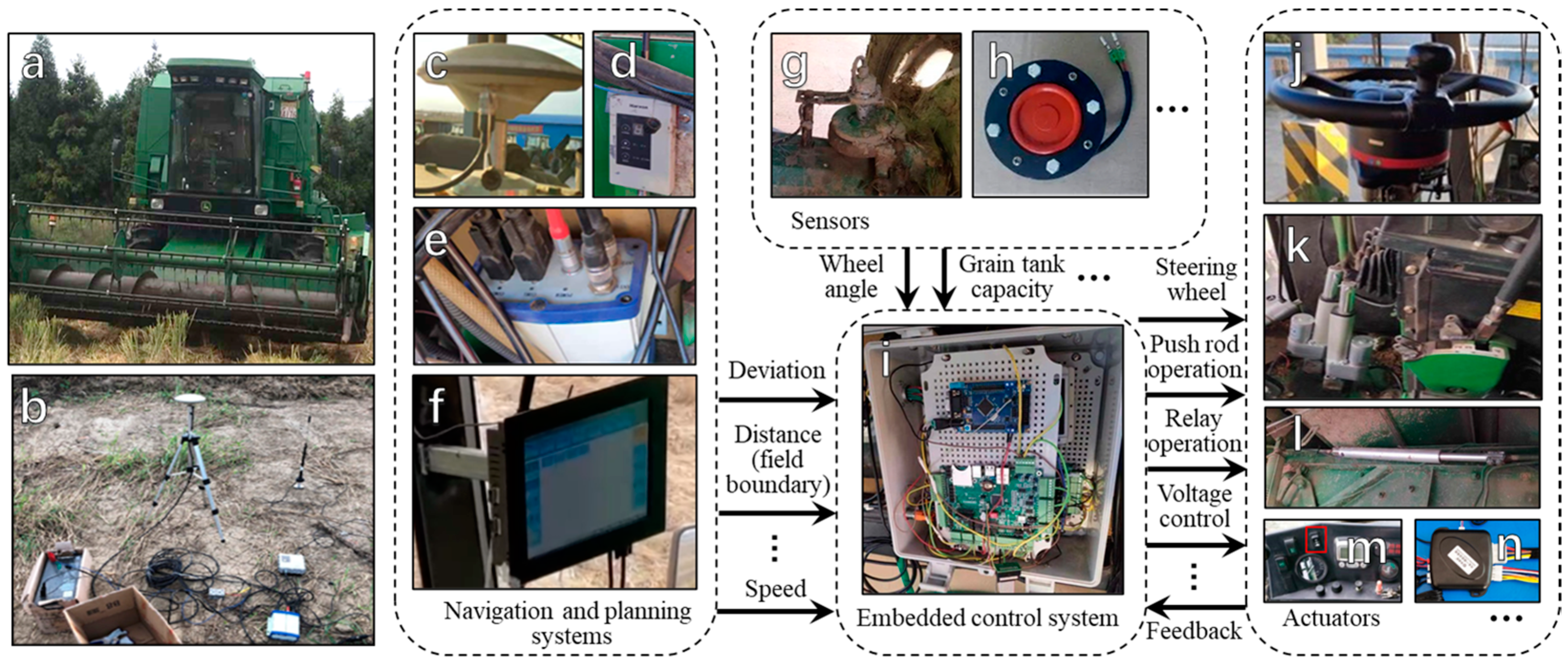
2.1. Overall Design of the Autonomous Driving System

This study was conducted using the John Deere C230 wheeled combine harvester platform, with the main parameters of the harvester listed in Table 1. The John Deere C230 model was selected due to its stability, maintainability, and widespread application in large-scale intensive agricultural operations, especially within state-owned farms in Shanghai, China. Its specialized rear-wheel-steered chassis design, along with its large cutting capacity and unique turning characteristics, provided a valuable complement to previous research that utilized different harvester chassis platforms [30,39]. The autonomous driving system consisted of several key components, including a navigation and path planning system, an embedded control system, sensors, and actuators, as illustrated in Figure 1.
Navigation and Path Planning System: This system used a positioning board (UB482, Beijing HeXin StarCom) to calculate the vehicle’s lateral deviation, heading deviation, and distance to the field boundary in real time. The industrial control computer running the software is shown in Figure 1f. The positioning system hardware also included an RTK base station, GPS antenna, RTK radio, and GPS-RTK decoding box, as illustrated in Figure 1b–e. The RTK system provided a horizontal positioning accuracy of 1 cm + 1 ppm and an elevation accuracy of 1.5 cm + 1 ppm, with a data update rate of 10 Hz, following the NMEA-0183 protocol. These positioning data were then transmitted to the embedded control system, which adjusted the vehicle’s travel trajectory accordingly [40].
Embedded Control System: This system, based on an industrial control board (EMB8600I, Beijing Zhongzhan Lingyun, Beijing, China), received deviation information from the navigation system and integrated sensor signals to control the actuators. The control board was powered by an STM32F107VCT6 chip, with its onboard resources optimized to meet the control requirements of this study. The development environment used was Keil5, with programming implemented in C, as shown in Figure 1i. It effectively combined path tracking and operational control [30,39].
Sensor Devices: To ensure the accuracy of path tracking and operational control, the system was equipped with various sensors, including a right rear wheel angle sensor (DWQCAB-V-CH, Beijing Tianhai Ke) and a grain tank level sensor (membrane contact pressure sensor, John Deere original). The angle sensor featured a linearity of 0.02% FS, an angular resolution of 0.022°, and an absolute accuracy of 0.10°. It was directly connected to the center of the wheel steering axis, with a measurement range that fully covers the wheel’s maximum left and right turning limits, as shown in Figure 1g. The grain tank sensor was mounted at the top of the grain tank’s inner wall, outputting a level signal upon contact with the grain pile, as shown in Figure 1h. These sensors continuously monitored the vehicle’s status, providing essential data to the control system for real-time adjustments and optimal performance.
Actuators: The actuator components included an electric steering wheel (EMS02, Shanghai Lianshi) for precise steering control, electric actuators (YNT03 feedback actuator, Nanjing Yongnuo Transmission) for implementing variable speed control, header lifting, and threshing clutch actions, an electronically controlled throttle (relay switching integrated on the industrial control board) for throttle gear selection, and two remote relay modules for remote start/stop functions. The electric steering wheel, with a rated speed of ±100 rpm, was installed in place of the original steering wheel and communicated with the embedded control system via an RS232 serial port, as shown in Figure 1j. The electric actuators were deployed in various complex scenarios, typically using a cable-pulling mechanism or by welding pushrod mounting points onto the vehicle’s structure to enable the electrified control of clutch engagement/disengagement, belt tensioning/releasing, gear shifting, and all other lever-type operations, as illustrated in Figure 1k,l. The harvester’s original throttle switch was a three-position toggle button, where each position corresponded to a resistance of 400 Ω, 1300 Ω, and 3000 Ω, respectively, in the engine control circuit. By integrating three electronically controlled throttle units into the vehicle control system, the same resistance values were applied to achieve electronic throttle switching, as depicted in Figure 1m. For remote ignition control, a remote relay module was connected in parallel to the ignition circuit, allowing remote activation. Similarly, another remote relay module was connected in series with the main ignition circuit to enable emergency shutdown, as shown in Figure 1n. All actuators were precisely controlled through electrical signals to ensure operational efficiency and reliability.
Autonomous driving system: The overall control block diagram of the autonomous driving system is shown in Figure 2. The navigation and positioning system transmitted the real-time vehicle speed, lateral deviation, and heading deviation. The data were processed using the Look-Ahead Ackermann path tracking algorithm to calculate the required rear wheel angle for correction. The target rear wheel angle was then input into the steering closed-loop control system, where the feedforward PID algorithm generated the control signal for the electric steering wheel, achieving accurate path tracking control for the harvester. The key parameters and symbols used in the algorithms are shown in Table 2.

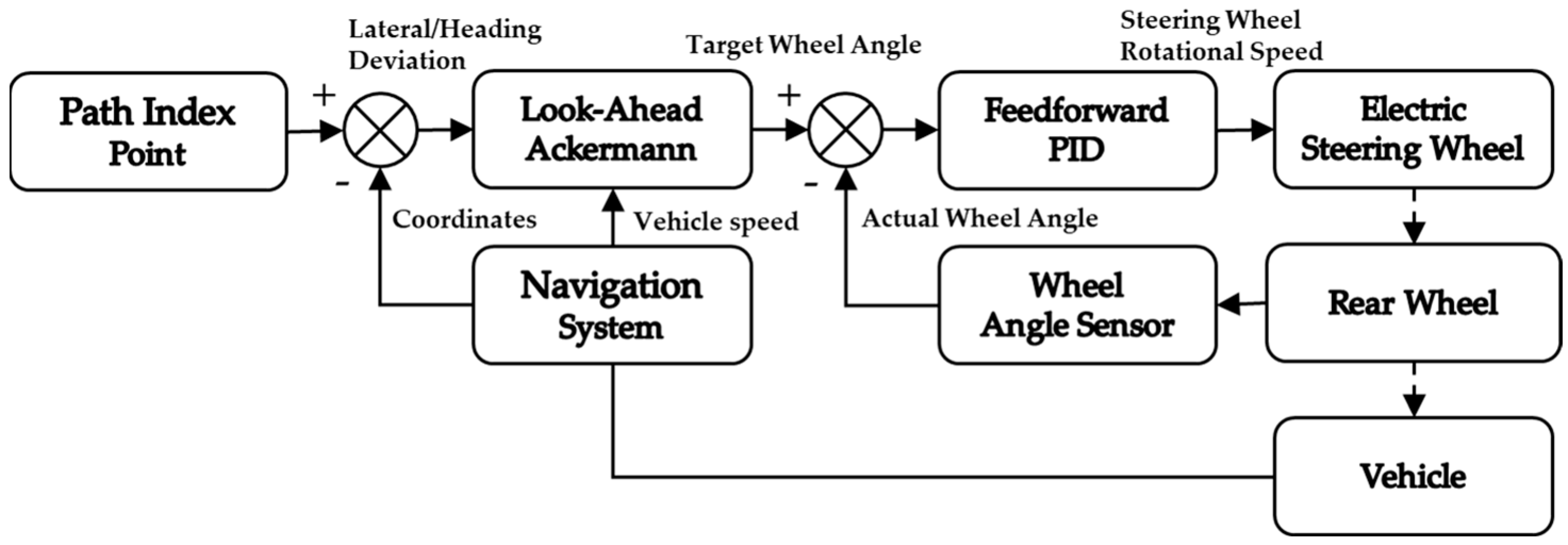
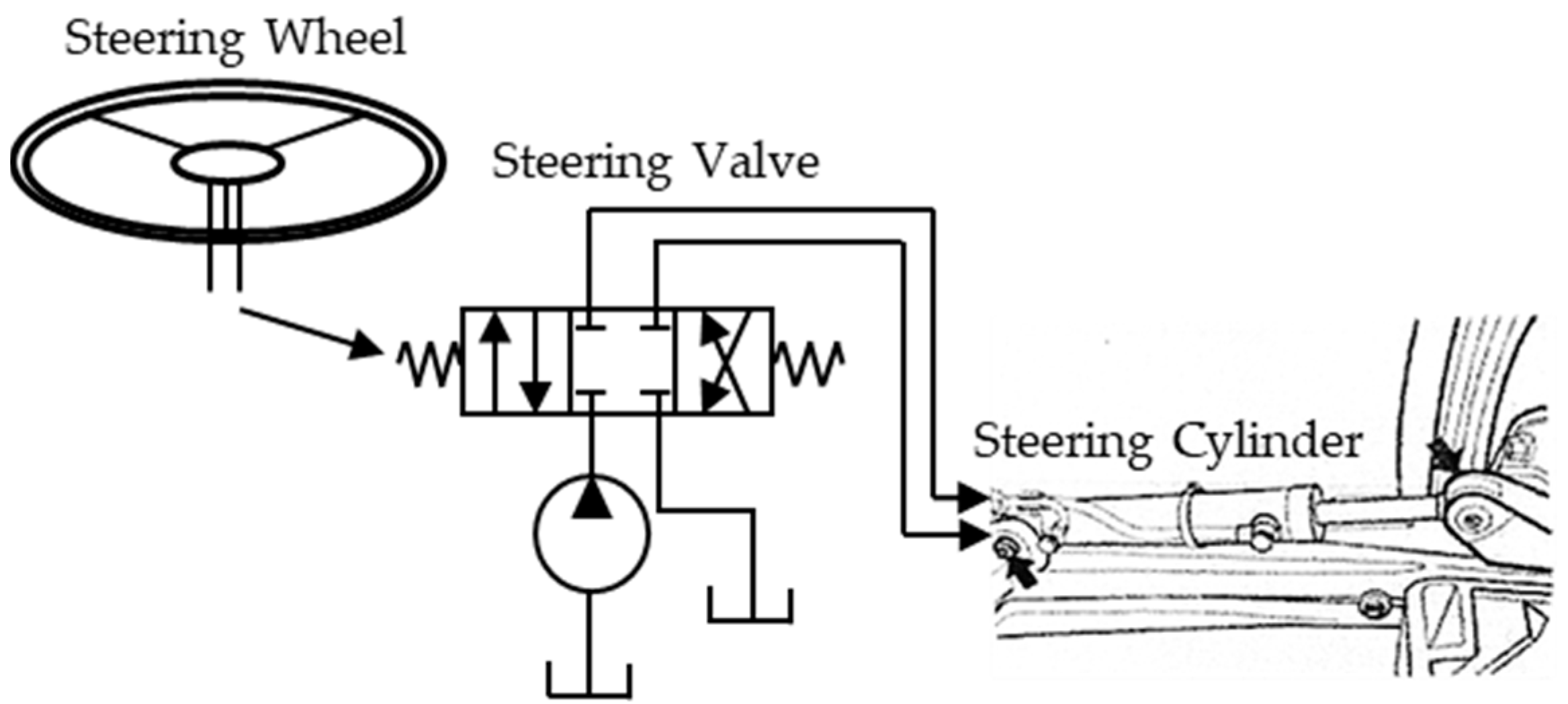
2.2. Feedforward PID Control of the Steering Wheel-Hydraulic Steering System

The C230 steering system uses an independent hydraulic circuit with full-hydraulic rear-wheel steering. The steering wheel drives a full-hydraulic steering unit, which in turn controls the steering cylinders of the two guide wheels in parallel, achieving full-hydraulic steering. A simplified diagram of the steering system is shown in Figure 3. Before designing the steering control algorithm, the linear relationship between the input and output of the controlled object was verified. The system being tested was the “steering wheel-hydraulic steering cylinder” system, where the impact of ground factors on the movement of the steering wheels must be minimized. In this study, a rotating platform with an angle sensor, as shown in Figure 4a, was designed. As depicted in Figure 4b, after lifting the vehicle’s right rear steering wheel with the designed rotating platform, the rotational speed and angle of the electric steering wheel (in the operator cab) were input, and the output from the wheel angle sensor was collected to conduct steering system identification experiments. The experimental results are shown in Figure 4c,d.
The identification experiments show that the relationship between the steering wheel angular velocity input and the rear wheel angular velocity output is approximately linear. Therefore, a PID controller was chosen as the main controller for the steering system. Additionally, an angular velocity control coefficient was designed to compensate for the differences in the left and right drive ratios, and a conditional feedforward controller was added to compensate for the free travel in the transmission structure:
μ k = k ω ( K p θ k + K i j = 0 k θ k + K d ( θ k θ k 1 ) ) + f f ( θ k )
where
k ω = 1.8 2.2 i f ( θ k θ k 1 ) > 0 , Left i f ( θ k θ k 1 ) < 0 , Right
and
f f ( θ k ) = 100 100 0 i f ( θ k θ k 1 ) ( θ k 1 θ k 2 ) < 0 & ( θ k θ k 1 ) > 0 i f ( θ k θ k 1 ) ( θ k 1 θ k 2 ) < 0 & ( θ k θ k 1 ) < 0 i f ( θ k θ k 1 ) ( θ k 1 θ k 2 ) 0

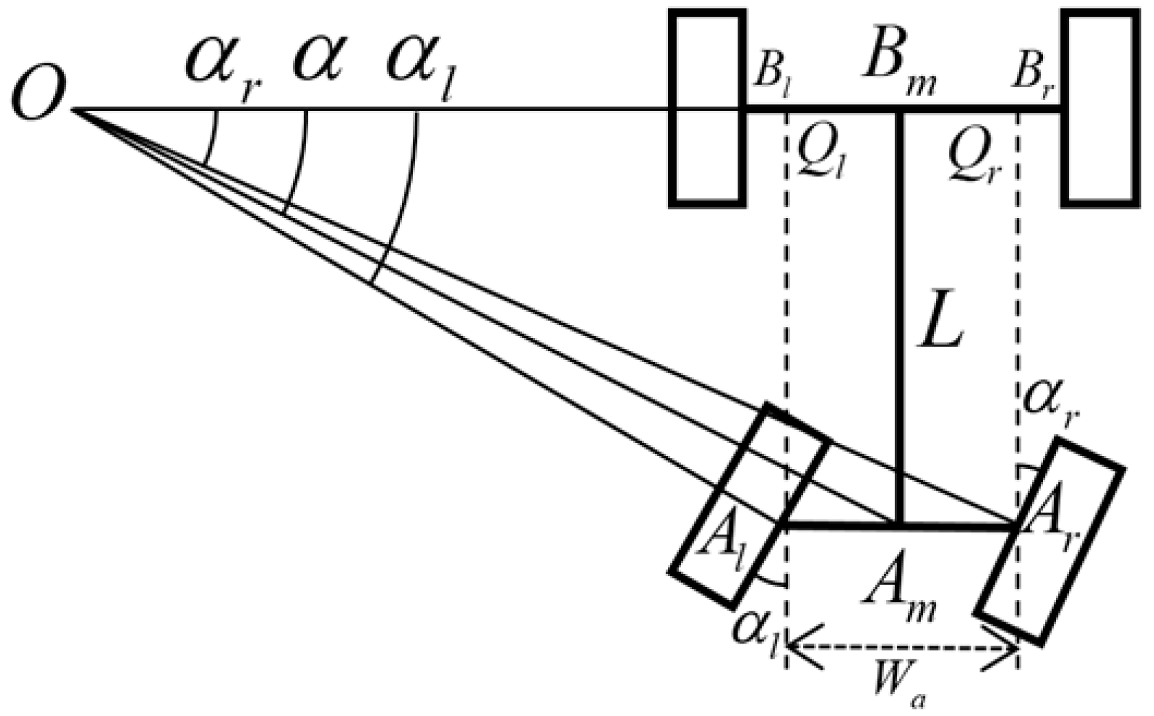
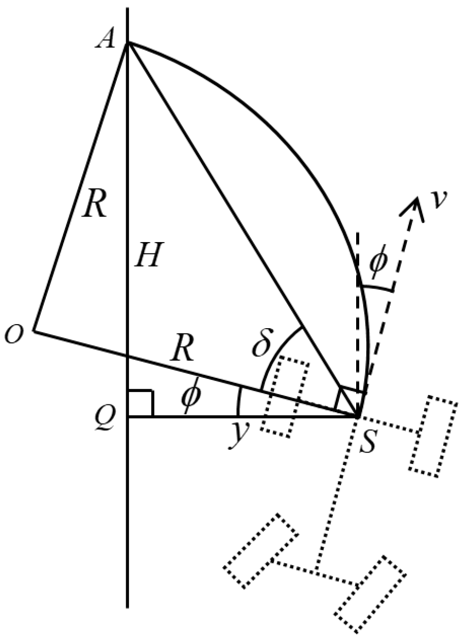
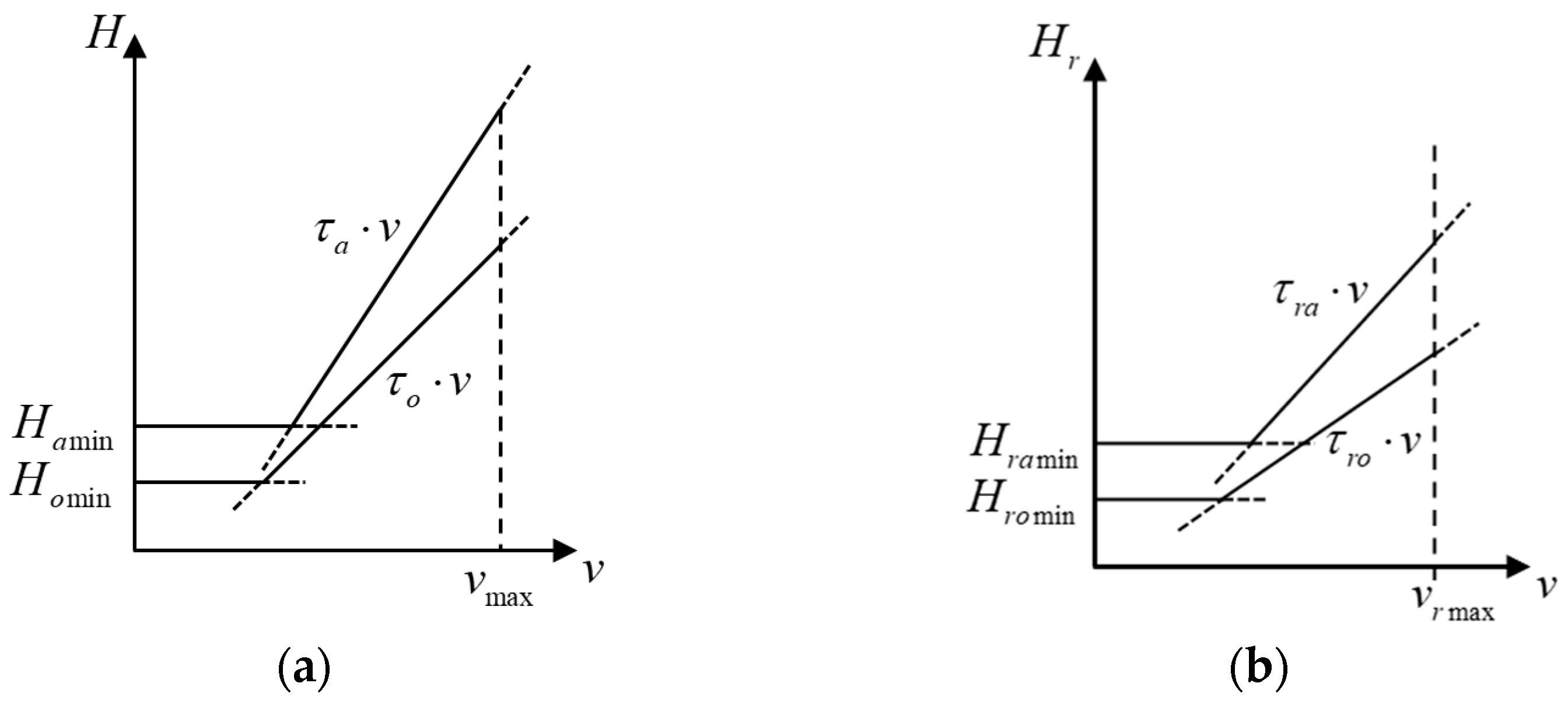
2.3. Look-Ahead Ackermann (LAA) Path Tracking Control

The Ackermann steering model is widely used in the kinematic control of various four-wheeled vehicles [41]. According to the Ackermann steering model, for a rear-wheel-steered vehicle, the vertical lines of all four wheels intersect at the vehicle’s instantaneous center of rotation during turning. The rotation angles of the left and right rear wheels are denoted as α L and α R , respectively, with the rear wheel track W a and the wheelbase L defined. The instantaneous center of rotation is denoted as O . The distance from the front axle’s center of the front wheel B m to the instantaneous center of rotation is defined as the turning radius R B m . The inverse of the turning radius is defined as the vehicle’s steering curvature θ . For convenience, we define the following symbols for turning conditions: when turning left, α l > 0 , α r > 0 , R B m > 0 ; for right turns, α l < 0 , α r < 0 , R B m < 0 ; and for straight-line driving, α l = α r = 0 , R B m = + , where the steering symbols “left positive, right negative” apply. This is depicted in Figure 5 for the left-turn Ackermann model.
Based on geometric derivation, the Ackermann steering equations for a left turn can be derived, and the same formula applies for right turns, with the uniform form as follows:
α = arccot R B m L α l = arccot R B m W a 2 L α r = arccot R B m + W a 2 L
Additionally, the relationship between the steering curvature and the rotation angles is derived as:
θ = tan α L θ = 1 L cot α l + W a 2 θ = 1 L cot α r W a 2
The core idea of the Look-Ahead Ackermann (LAA) algorithm is illustrated in Figure 6. Starting from time t 0 , the vehicle moves at a certain speed. At regular intervals, the current position of the vehicle (the center of the front axle) S i projects a point onto the target path ahead by a fixed distance (or behind when reversing), defining a “look-ahead point A i ”. This distance is called the look-ahead distance (denoted as H ), as shown in the diagram. By combining the vehicle’s real-time lateral deviation y and heading deviation ϕ with the Ackermann steering model, the real-time target steering angle for the rear wheels is calculated.
The LAA formula for forward movement is derived under four conditions: 1. the vehicle is to the right of the target path, the heading deviates right ( y > 0 , ϕ > 0 , R > 0 ); 2. the vehicle is to the right of the target path, the heading deviates left ( y < 0 , ϕ < 0 , R < 0 ); 3. the vehicle is to the left of the target path, the heading deviates left ( y > 0 , ϕ < 0 , R < 0 ); 4. the vehicle is to the left of the target path, the heading deviates right ( y < 0 , ϕ > 0 , R > 0 ). For case 1, as illustrated in Figure 7, the derivation proceeds as follows:
According to the previous definitions, the distance from the vehicle’s position S to the projection point on the target path Q is the lateral deviation y , and the angle between the vehicle’s velocity v and the target path is the heading deviation ϕ . The distance between the projection point Q and the look-ahead point A is the look-ahead distance H . To reach the look-ahead point, the vehicle needs to steer with a turning radius R and the steering arc should pass through point S and be tangent to the vehicle’s central axis at the point. The LAA auxiliary angle δ is the acute angle of the right-angled isosceles triangle A O S . The turning radius is calculated based on the geometric relationship:
R = H 2 + y 2 2 y cos δ + H sin δ
Substituting the target turning radius from the LAA algorithm into Equation (4) results in the Ackermann steering model formula, which is used to calculate the steering angles for each wheel:
α l = arctan 2 L ( y cos ϕ + H sin ϕ ) ( H 2 + y 2 ) W a ( y cos ϕ + H sin ϕ ) α r = arctan 2 L ( y cos ϕ + H sin ϕ ) ( H 2 + y 2 ) + W a ( y cos ϕ + H sin ϕ ) α = arctan 2 L ( y cos ϕ + H sin ϕ ) H 2 + y 2
Similarly, the derivation is performed for the other cases, and with the condition “left turn positive, right turn negative, lateral deviation left negative, right positive,” the vehicle has a unified LAA formula for forward movement. For reverse driving, there are four conditions to consider, and the LAA formula for reverse operation is derived as follows:
α l = arctan 2 L ( y cos ϕ H sin ϕ ) ( H 2 + y 2 ) W a ( y cos ϕ H sin ϕ ) α r = arctan 2 L ( y cos ϕ H sin ϕ ) ( H 2 + y 2 ) + W a ( y cos ϕ H sin ϕ ) α = arctan 2 L ( y cos ϕ H sin ϕ ) H 2 + y 2
Compared to the forward formula, the only difference is the substitution of ϕ . Since the wheel angle sensor in this study is installed on the right rear steering wheel, particular attention is given to the formula
α r = arctan 2 L ( y cos ϕ + H sin ϕ ) ( H 2 + y 2 ) + W a ( y cos ϕ + H sin ϕ )
which corresponds to the forward driving state during harvesting operations.
α r = arctan 2 L ( y cos ϕ H sin ϕ ) ( H 2 + y 2 ) + W a ( y cos ϕ H sin ϕ )
which corresponds to the reverse driving state required for turning at the field boundary.
Overall, the LAA algorithm mimics the human driving experience [42], so the definition of the look-ahead distance is also similar to how humans perceive it: at low speeds, the “human eye” observes a fixed minimum distance along the target path ahead ( H = H m i n ), and at higher speeds, the look-ahead distance increases accordingly ( H = τ   v , where τ is proportional to the look-ahead time, measured in seconds). The basis for controlling the vehicle’s movement is the Ackermann steering model. The same logic applies for reverse movement. Additionally, when the lateral or heading deviation exceeds a threshold ( y > y a / o or ϕ > ϕ a / o ), the vehicle must make larger posture adjustments, known as the “approach” process. During this process, the look-ahead distance should be relatively larger when deviations are small, known as the “online” process, to avoid excessive steering angles and prevent large overshoot errors due to system delays.
The quantification of the look-ahead distance is presented in Figure 8.
The definitions of look-ahead distances for forward “approach” mode are:
H a = max ( H a min , τ a v ) y > y a | o | | ϕ > ϕ a | o ,   0 < v < v max
For forward “online” mode:
H o = max ( H o min , τ o v ) y > y a | o & & ϕ > ϕ a | o ,   0 < v < v max
For reverse “approach” mode:
H r a = max ( H r a min , τ r a v ) y > y a | o | | ϕ > ϕ a | o ,   0 < v < v r max
For reverse “online” mode:
H r o = max ( H r o min , τ r o v ) y > y a | o & & ϕ > ϕ a | o ,   0 < v < v r max
The LAA algorithm is also applicable to curved paths; however, to prevent sudden control fluctuations caused by changes in the look-ahead point, the look-ahead distance should be reduced, and the vehicle speed appropriately lowered at the transition between curved and straight segments to ensure high-precision path tracking.

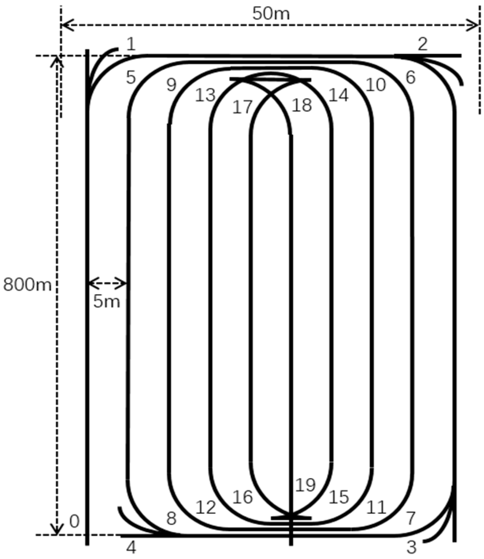
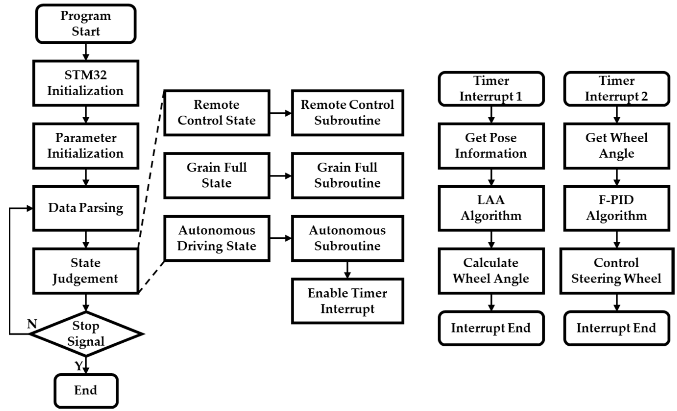
2.4. Realization Strategy of the Whole-Field Autonomous Driving Control

The John Deere C230 combine harvester has a cutting width of 5.4 m and a minimum turning radius of 9.2 m. When turning without reversing, it requires skipping at least three rows to avoid crossing into an unharvested path. In other words, if the spacing at the field boundary is less than three rows, a reversing maneuver must be introduced. Additionally, the C230 harvester can only unload grain on the left side, so the harvesting path must begin at the “lower-left corner” of the field and proceed inward in a “loop pattern” toward the center. Since the harvester’s wide cutting width can cause the header to flatten the crops at sharp turns, a single 90° turn in crop-covered corners is replaced by three consecutive 30° turns, integrating forward and reverse movements, named “three-cut” turning. This steering method allows the harvester to clear the four corners of the field during the first round of harvesting, forming an arc-shaped boundary that matches the harvester’s turning radius, thereby facilitating smooth subsequent turns. The target field is a standardized farmland measuring approximately 800 m in length and 50 m in width, laid out with 10 rows of straight-path operations. The headland turning paths use a quarter-circle arc combined with cross-row straight lines.
Figure 9 shows the final whole-field operating path designed for the John Deere C230 harvester. The numbers 0–19 in the figure indicate the sequence in which the harvester travels through the paths. Among these, corner points 1–4 require the “three-cut” turning method. All cross-row paths overlap; thus, once rows 1–4 on the outermost loop are fully harvested, no further harvesting is needed for those paths. The cross-row sections between points 15–16 and 17–18 require the harvester to reverse.
Figure 10 illustrates the software flowchart of the autonomous driving system. Various serial communication data are received via interrupts plus DMA, then parsed into different data-parsing functions to assign values to corresponding variables. An emergency stop signal is accessed through a hardware pull-down, connected to a pulse input capture interface, and verified with a delay in the interrupting service routine to avoid false triggers. In remote-control and “grain tank full” states, subroutines adopt sequential logic, and timers 1 and 2 are disabled. Under the autonomous driving state, the operation-related functions use sequential logic, and the steering functions are executed through timers 1 and 2. Timer 2, used for closed-loop control of the steering wheels, has a higher trigger frequency and priority than timer 1, which handles trajectory tracking control. Timer 1 is synchronized with the navigation data update cycle, with a trigger period of 100 ms. Timer 2 has a trigger period of 10 ms. All algorithm computations are completed within their respective timer cycles, ensuring high computational efficiency. The response time of each actuator is constrained by its own performance and is slower than the timer cycle. However, since the actuators can continuously respond to commands (e.g., the electric steering wheel cannot undergo abrupt speed changes), erroneous actions are avoided. As a result, the overall system response time meets the application requirements. An additional, even higher-priority timer interrupt is used as the system clock. As there are multiple interrupts in the program, their priorities must be arranged according to practical needs. In general, the data processing capability and response speed of the embedded controller meet the application requirements.

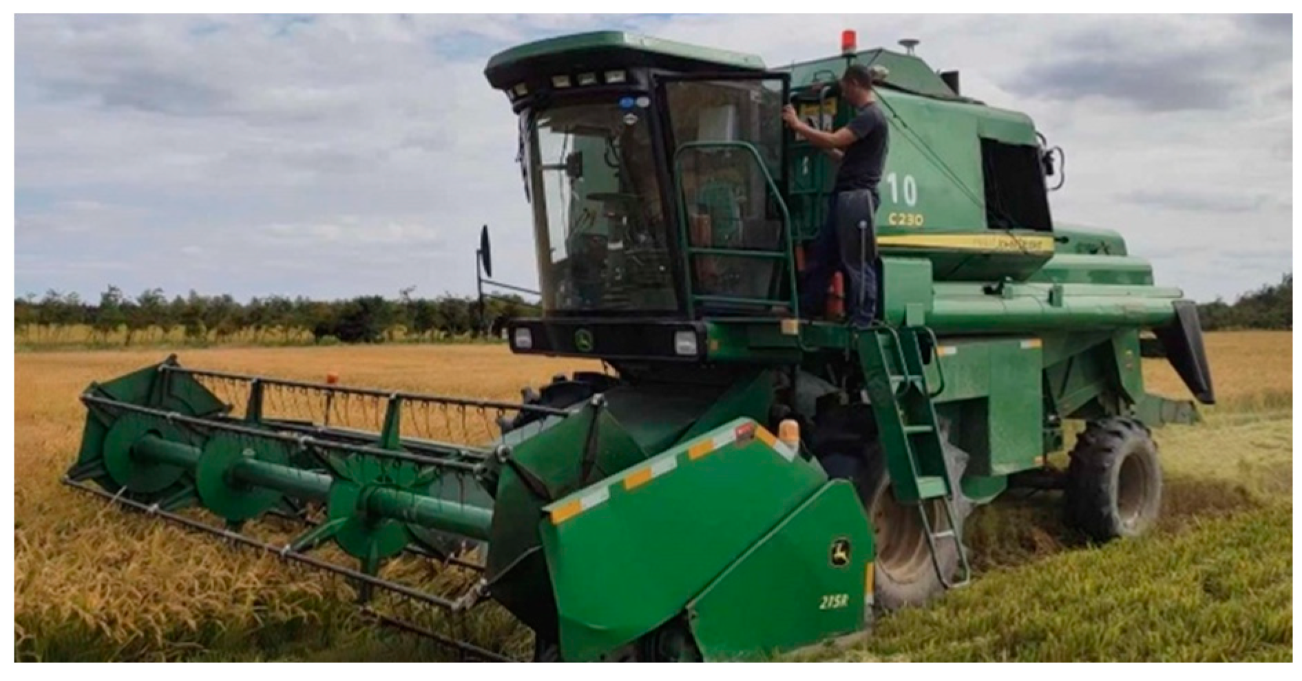
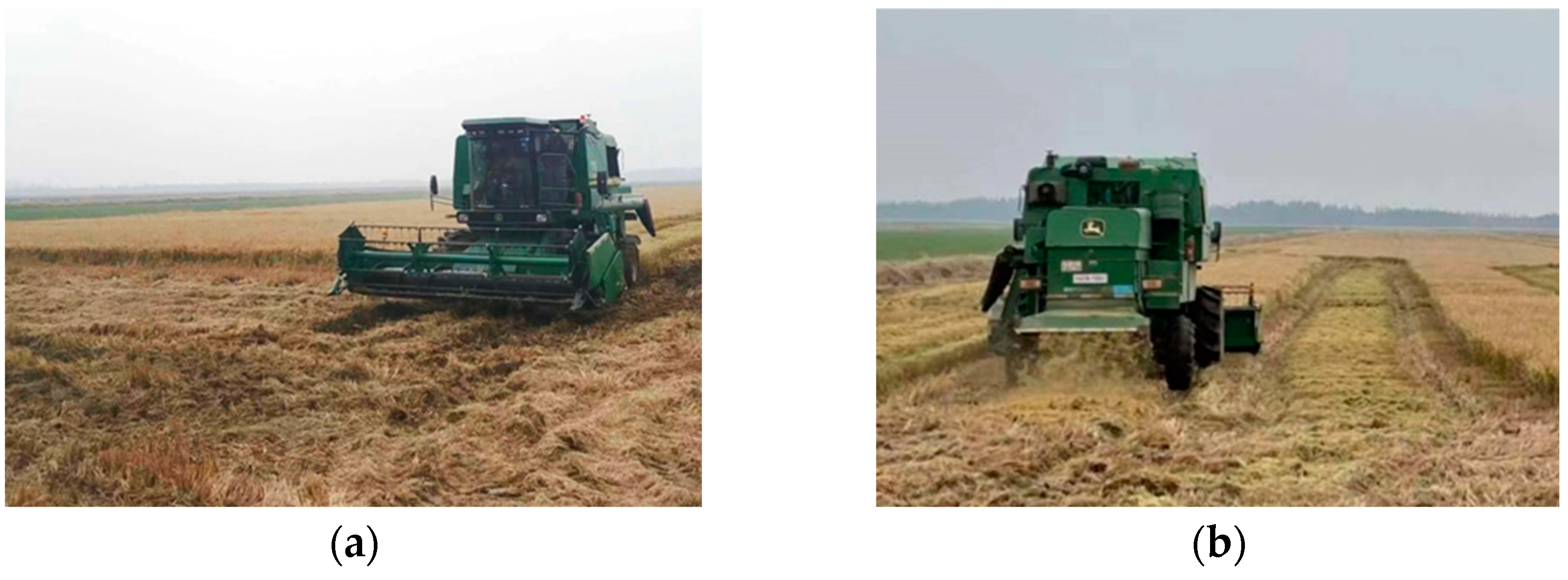
3. Experiments and Results

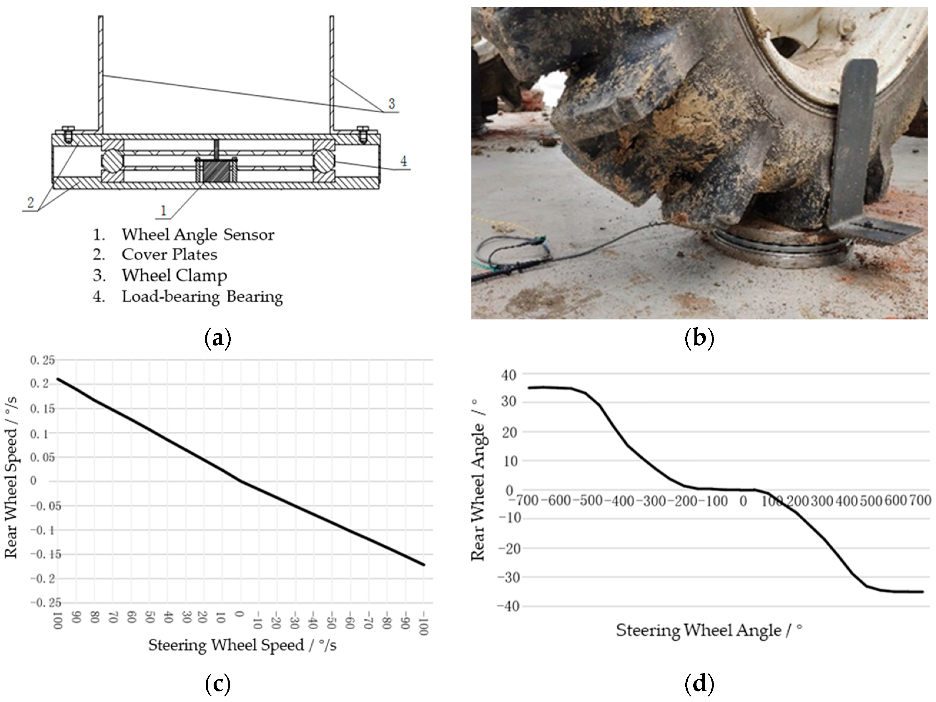
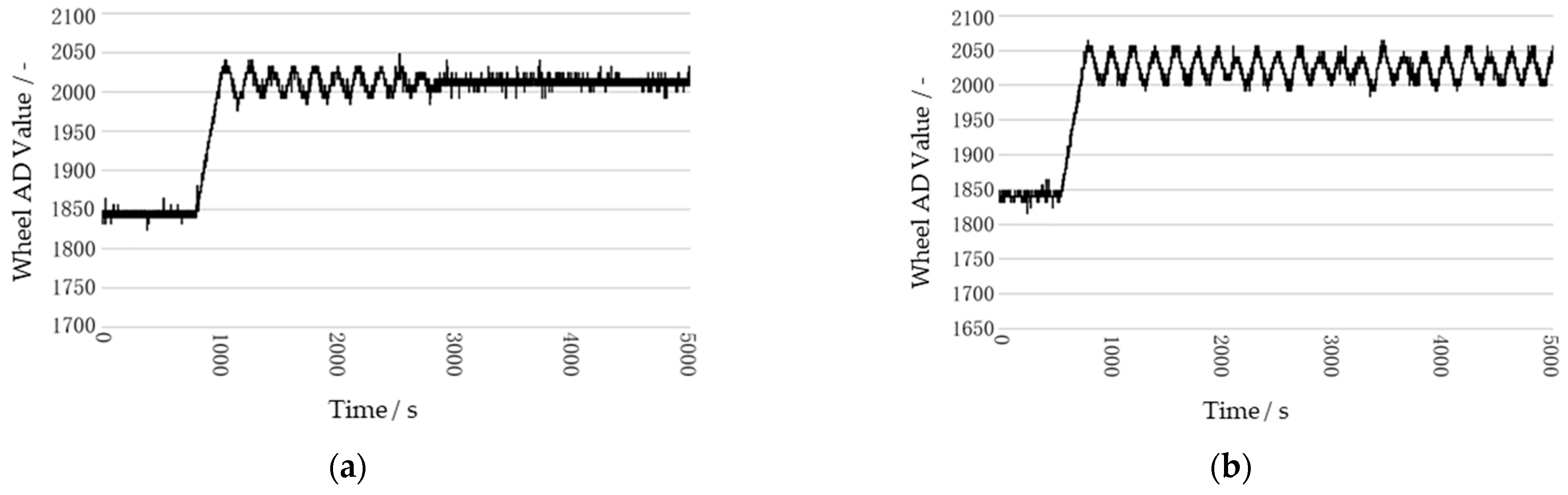
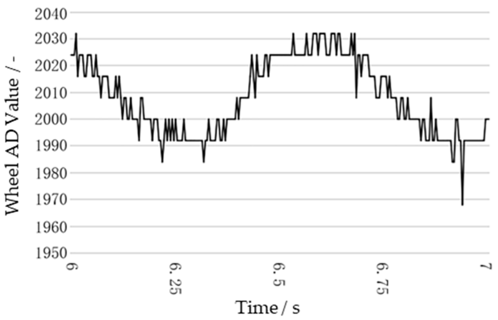
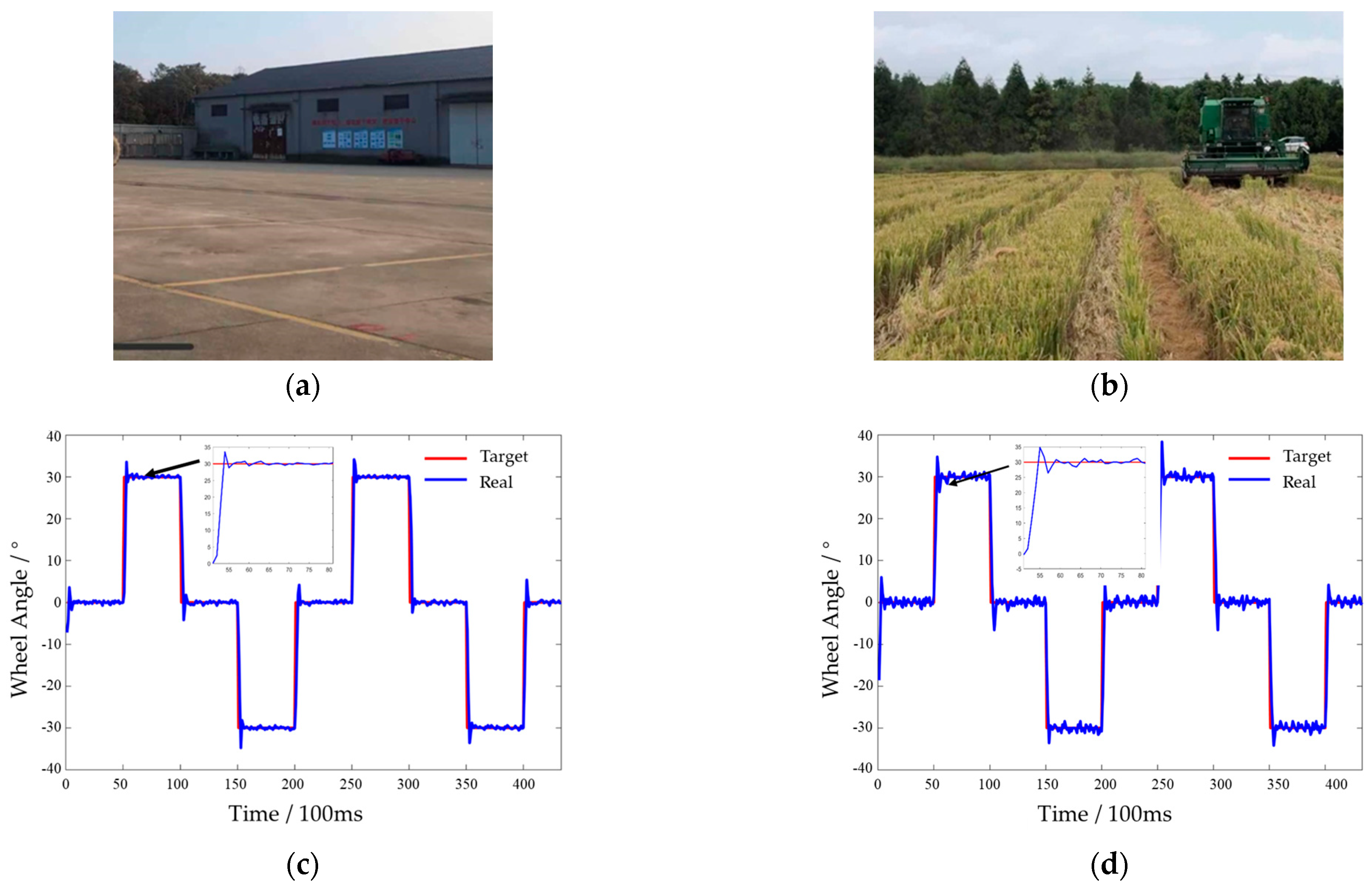
3.1. Performance Test of the Steering System

When using the Ziegler–Nichols (ZN) empirical method to tune PID parameters [43], extensive model parameters or direct acquisition of the test object’s step response curve are typically required, which can be time-consuming and data-intensive in practice. By contrast, the critical proportional method does not depend on the model parameters of the controlled object. Instead, it obtains the optimal tuning parameters for the PID controller via two parameters describing the dynamic characteristics of the controlled system combined with empirical formulas. Moreover, in this study’s control scenario—namely, the “steering wheel angular velocity–rear wheel angle” system—no step response curve can be acquired under open-loop conditions. Hence, the critical proportional method is applied in a closed-loop setting, where the integral and derivative terms of the PID controller are removed, and the proportional gain K p is adjusted so that the closed-loop system undergoes sustained oscillations of constant amplitude under disturbance. In this state, the proportional gain is called the critical gain K u , the system’s critical proportionality δ u = 1 / K u , and the corresponding oscillation period is called the critical oscillation period T u . Using the experimental platform mentioned in Figure 4, a disturbance θ = 30 ° was introduced at the critical gain K u = 4.9 , and the system’s angle AD values were recorded under critical oscillation, as shown in Figure 11. To measure the critical oscillation period more conveniently, the interval t = [ 6,7 ] was selected to calculate T u = 0.6 , as shown in Figure 12.
With δ u = 1 / K u = 0.204 and T u = 0.6 , the empirical formula for the critical proportional method is shown as:
K p = 1 1.7 δ u 2.88 K i = K p 0.5 T u 9.61 K d = 0.125 K p T u 0.22
To verify the performance of the steering system using the described F-PID control algorithm, two sets of steering tracking experiments were conducted under different road conditions. One test site was a concrete surface at the Shanghai Chongming Dongtan Shangshi Farm Machinery Station, and the other was a harvested rice field with dry stubble, also at Shangshi Farm. In these experiments, a square wave of steering angle commands was used as the steering input. The controller sampled the rear steering wheel angle signal at fixed intervals. Using the Z-N method to tune the parameters, there was significant lag in the PID steering control, which necessitated optimization based on actual effects. After reducing the integral coefficient K i by a factor of 10 2 , the control performance improved. The testing sites and data collected are shown in Figure 13. The testing results are shown in Table 3.

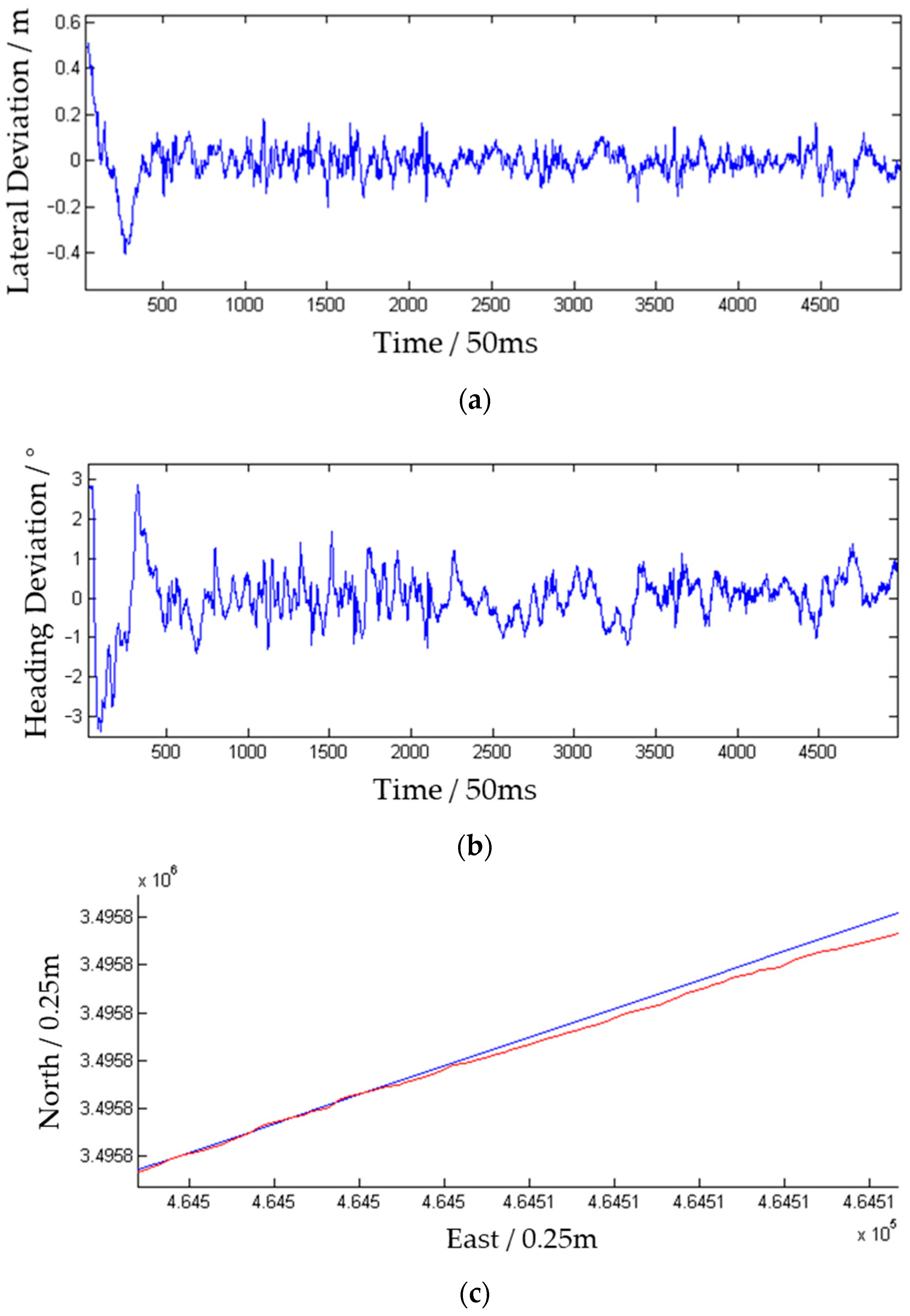
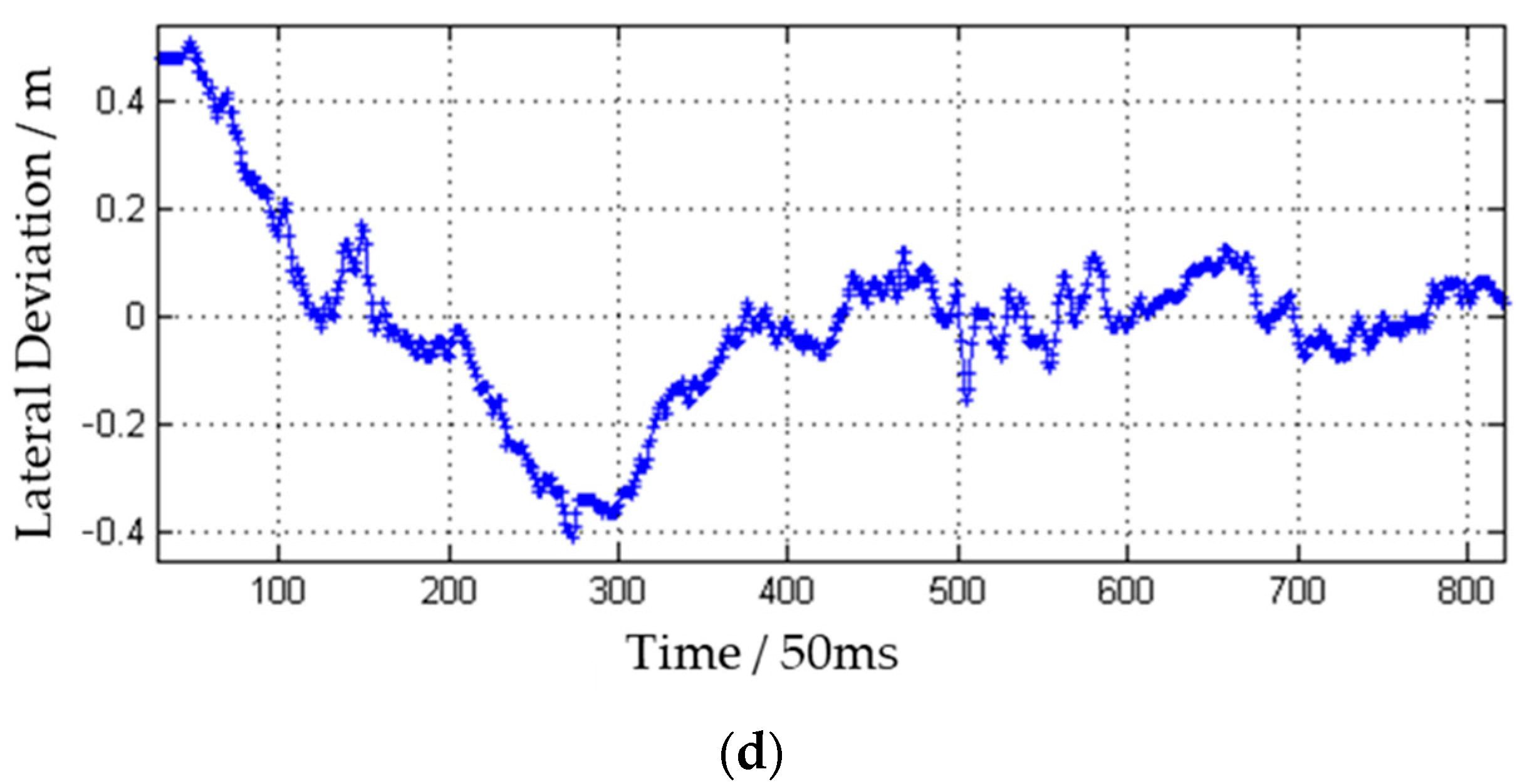
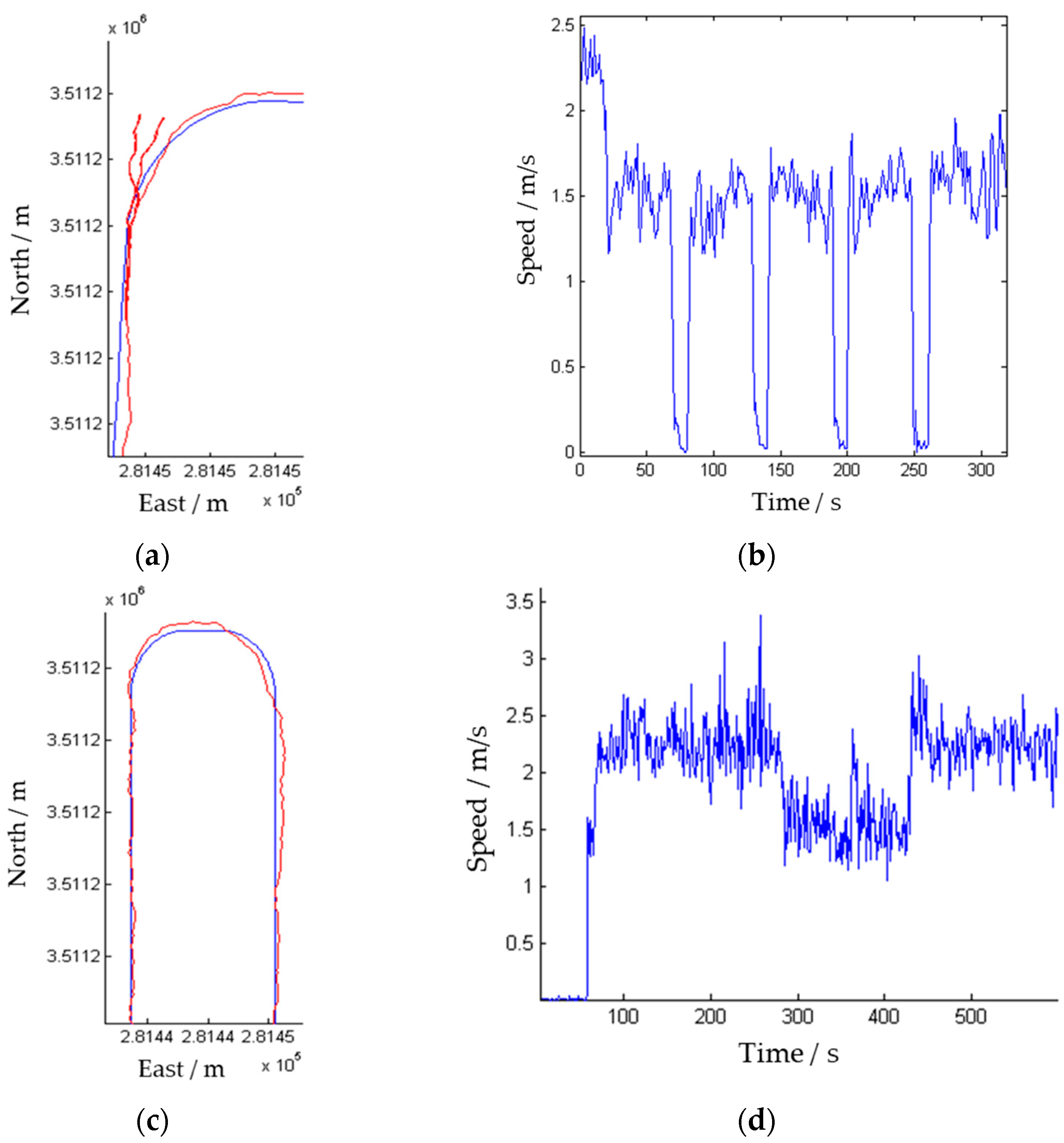
3.2. Field AB-Line Operation Experiment

To validate the performance of the LAA-based straight-line path tracking algorithm presented, a field AB-line autonomous driving experiment was conducted on an unharvested rice paddy at Shangshi Farm in autumn. The rice variety used was Nanjing 46, with a crop-straw ratio of 1.28 and an overall moisture content of 32.7%. When the harvester started, it had an initial lateral deviation of +0.5 m and an initial heading deviation of +3°. The harvesting speed was set at 1.2 m/s. Operating under autonomous driving mode, it moved from northeast to southwest along the edge of the field while harvesting. Post-harvest field images are shown in Figure 14a,b, where the stubble boundary visually indicates the straight-line tracking accuracy. The navigation and positioning system recorded the lateral deviation data for the first 300 m, shown in Figure 15a, and the heading deviation in Figure 15b. The “approach” phase of the AB line was magnified for closer observation, as shown in Figure 15c. The lateral deviation during this phase is in Figure 15d. The main experiment results are shown in Table 4.

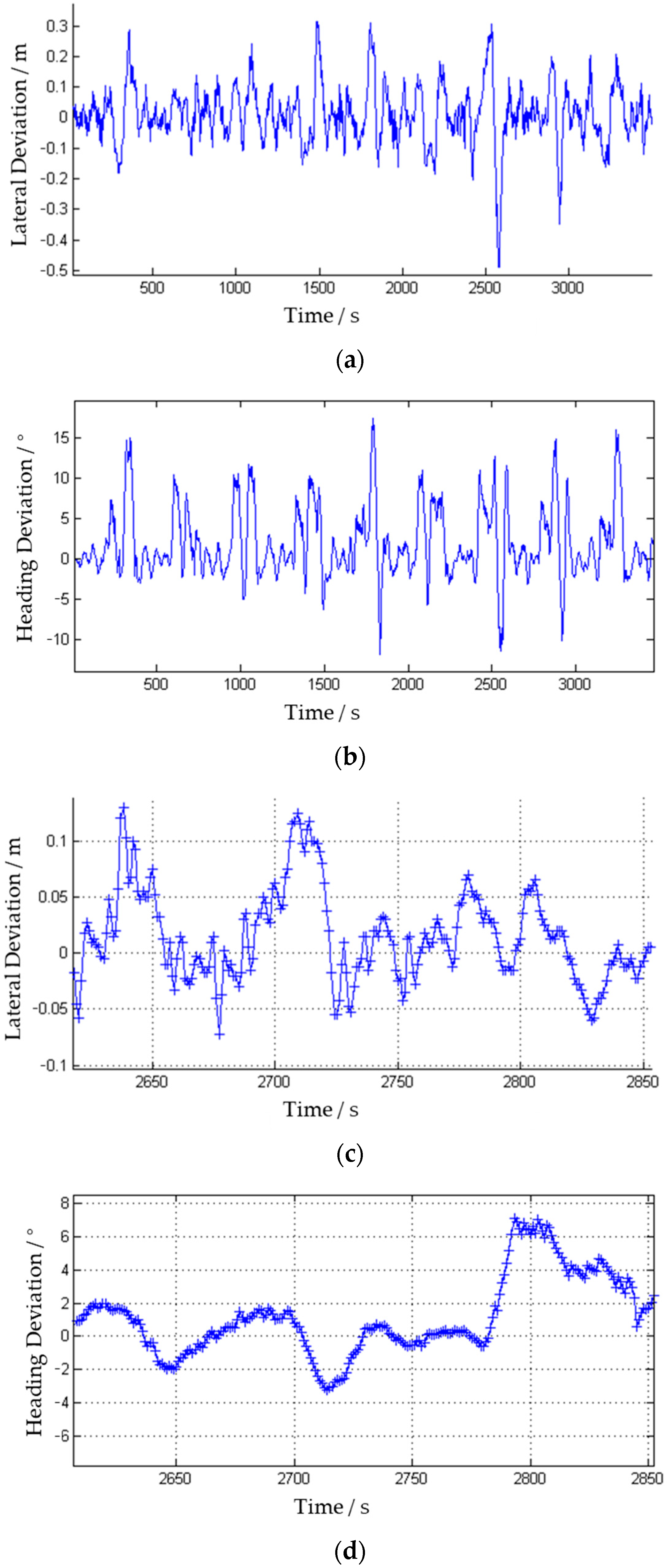
3.3. Complete “Loop” Field Operation Experiment

Since the John Deere C230 harvester can only unload grain on the left side, the machine must harvest the field from the outside inward in a “loop pattern” to ensure unloading vehicles can approach correctly. To validate the autonomous system’s ability to manage full-field operations, a comprehensive field experiment was conducted in autumn at Shangshi Farm on a standardized 800 m × 50 m rice paddy awaiting harvest. The rice variety used was Nanjing 46, with a crop-straw ratio of 1.35 and an overall moisture content of 27.4%. The soil was relatively dry, and the tire had no obvious skid when the harvester was running normally. The harvesting speed was set at 2.2 m/s. The experimental site is shown in Figure 16.
The harvester worked from the lower-left corner to harvest the entire field. The navigation and positioning system recorded the lateral deviation data, shown in Figure 17a, and the heading deviation data, shown in Figure 17b. The largest lateral and heading deviations occurred during turning enlarging the straight-line portion’s data, shown in Figure 17c (lateral deviation) and Figure 17d (heading deviation).
To avoid flattening crops at sharp turns when harvesting, the harvester used a “three-cut” turning method on curved sections of the path, as shown in Figure 18a. The corresponding speed data are shown in Figure 18b (where the navigation system recorded speed as an absolute value, without direction differentiation). When not actively harvesting during cross-row traverses, the harvester lifted the header and slowed down. This cross-row trajectory is shown in Figure 18c, and the corresponding speed data are shown in Figure 18d. Because the size of the horizontal and vertical coordinates differs by 10 times in Figure 18a,c, the size of the lateral deviation in the trajectory is significantly amplified. The deviation in the actual turning process was within the redundancy range of the cutting width (the C230 harvester had a cutting width of 5.4 m, but the planned working width was 5 m).
The harvester’s performance while turning at the field headland is shown in Figure 19a, and its row alignment after the turn is illustrated in Figure 19b. The measured unharvested crop area after harvesting was approximately 10 m2. Dividing this by the total field area resulted in a crop loss rate of 0.25 ‰. The main experiment results are shown in Table 5.

4. Discussion

From the experimental data, the following results are obtained:
1. Steering System Performance: In the steering experiment, the rear steering wheel angle on concrete surfaces settled in approximately 1.5 s with an overshoot of about 13%. Under dry, standard field conditions, settling took around 2 s with an overshoot of about 17%. Although feedforward control enhanced the convergence speed, it also made the system more prone to oscillations caused by disturbances. Overall, the steering tracking performance of the electric steering–hydraulic steering system, controlled by the F-PID approach, meets practical application requirements. Further research on more advanced closed-loop steering control algorithms can be conducted in the future.
2. Field AB-Line Operation: In the AB-line field operation experiment, the harvester’s lateral deviation converged to within 10 cm in approximately 25 s, completing the approach phase. The relatively low preset speed and conservative controller parameters in the AB-line test impacted the vehicle’s line acquisition speed, leading to a slower convergence. During steady-state operation, the maximum lateral deviation was approximately −19.4 cm, with an average absolute deviation of 4.3 cm. The stubble boundary observed in the rice field after the AB-line experiment visually corroborated the system’s high straight-line tracking performance.
3. Complete “Loop” Field Operation: The results from the complete “loop” field operation experiment indicated that the harvester’s autonomous driving system successfully completed harvesting across the entire field. During the straight-line segments, the maximum lateral error remained below 20 cm, with an average absolute deviation of about 5 cm, while also meeting the turning requirements of harvesting operations. Additionally, given that the C230 is a large harvester with inherent challenges in achieving precise control, its 5.4 m cutting width and planned operating width of 5 m ensured that even the maximum observed deviation remained within acceptable redundancy limits, effectively preventing unharvested crop strips. The crop loss rate for the entire field was 0.25‰. The field experiments demonstrated the wheeled combine’s autonomous driving system provided high-precision path tracking suitable for harvesting needs.
This research also has the following potential limitations:
1. Limited Variety of Field Conditions: The experiments were primarily conducted in a harvested rice field and on a concrete surface. While these environments provided insights into both “ideal” conditions (smooth concrete) and relatively typical field conditions (dry stubble), they did not fully encompass more challenging scenarios such as muddy fields, uneven terrain, or densely planted crops. This study presented a calibration tool and method for steering systems that eliminate ground interference; however, the calibrated parameters cannot be universally applied to steering processes under varying ground conditions. In field experiments, the steering control parameters were still adjusted based on actual performance. Additionally, this study did not perform a dynamic analysis of steering behavior under different ground conditions. In real-world applications, terrain variability can significantly impact steering control performance. If the nonlinear friction model is considered [44], the adaptability to the change in friction force at low speed and high torque may be improved.
2. Focus on Rear-Wheel Steering: The study centered on a wheeled harvester with rear-wheel steering and an electric steering wheel mechanism. This configuration might not generalize as effectively to other four-wheel steering systems, tracked vehicles without Ackermann geometry, or other specialized farm machinery designs that require different control strategies.
3. Limited Algorithm Scope (F-PID + LAA): The control approach integrated feedforward PID and Look-Ahead Ackermann algorithms, which proved effective for path tracking. However, even though the autonomous driving error remained within the cutting width redundancy, the maximum path tracking error across the entire field reached 20 cm, which was still relatively large. This deviation may stem from the inherent 2 cm dynamic error of RTK, compounded by field-induced vibrations that cause oscillations in the roof-mounted positioning antenna. Advanced methods—such as adaptive algorithms, integration of inertial devices for enhanced navigation, or more robust controllers—could potentially improve resilience to disturbances, mitigate parameter uncertainties, and enable more adaptive control under rapidly changing conditions, areas that were not extensively explored in this study. Additionally, this study did not model the entire system or conduct simulation analysis, which limits the application of more advanced algorithms.
4. Absence of Detailed Harvest Operation Control: While this study focused on autonomous navigation and path tracking, it acheived fully autonomous harvesting requirements, including real-time speed regulation, header height adjustment, and threshing system optimization. The lack of integration between path-following control and machine operation control limits the system’s ability to perform optimally under varying crop and field conditions.
5. Additional Limitations Discussion: Energy consumption, vehicle efficiency, control system stability under dynamic conditions, potential failure modes, and overall system robustness were not extensively explored in this study and will be addressed in future research to enhance practicality and reliability.
Addressing these limitations—by expanding tests into more complex environments, integrating more advanced control algorithms, and developing fully automated harvester operation control—would significantly enhance the practical applicability and robustness of the proposed system for real-world autonomous harvesting.

5. Conclusions

1. Effective Integration of F-PID and LAA: This study successfully integrated a feedforward PID (F-PID) control with the Look-Ahead Ackermann (LAA) algorithm for path tracking in a large, rear-wheel–steered combine harvester. Field experiments confirmed that this integrated control strategy significantly improved lateral deviation performance, enabling precise path-following under typical agricultural conditions.
2. Validated Steering System Performance: The electric steering wheel–hydraulic steering system was evaluated in both concrete and harvested rice field environments. Results indicated a settling time of approximately 1.5 to 2 s, with an overshoot range of 13–17%. While feedforward control improved convergence speed, it also increased sensitivity to disturbances. However, this trade-off remains acceptable in achieving the necessary steering precision.
3. High-Precision Path Tracking in Field Operations: During AB-line field experiments, lateral deviations converged within 10 cm after 25 s, with a maximum steady-state deviation of 19.4 cm and an average of 4.3 cm. In a complete “loop” harvest scenario, the system successfully met turning and cross-row operation requirements while keeping lateral error extremes below 20 cm on straight-line segments. Given that the C230 is a large harvester with inherent challenges in achieving precise control, its 5.4 m cutting width and planned operating width of 5 m ensured that even the maximum observed deviation remained within acceptable redundancy limits, effectively preventing unharvested crop strips.
4. Practical Feasibility and Further Development: The implemented control framework demonstrates the feasibility of integrating autonomous navigation into existing commercial harvesters, advancing efficiency and labor-saving practices in agriculture. While the system has demonstrated promising results, future research should focus on refining adaptive algorithms, integrating inertial devices for enhanced navigation, and developing more robust controllers. Additionally, expanding testing across diverse field conditions and achieving full automation of the harvesting process—including speed regulation, header height adjustment, and threshing operations—will be crucial. These advancements will further enhance the system’s reliability, efficiency, and applicability in real-world farming environments.
Overall, this research confirms that the combination of F-PID and LAA algorithms for autonomous driving control in wheeled harvesters provides a valuable complement to previous studies employing different harvester chassis platforms [30,39]. It also establishes a solid foundation for achieving high-precision path tracking in autonomous agricultural operations.

Author Contributions

Conceptualization, S.Z. and X.W.; methodology, S.Z.; software, S.Z.; validation, Q.L., H.X., and Z.Y.; formal analysis, Q.L.; investigation, Q.S.; resources, X.W.; data curation, X.H.; writing—original draft preparation, S.Z.; writing—review and editing, S.Z.; visualization, X.H.; supervision, X.W.; project administration, Q.S.; funding acquisition, X.W. All authors have read and agreed to the published version of the manuscript.

Funding

This project is supported in part by the National Key Research and Development Program of China (2022ZD0115804), Project of Faculty of Agricultural Engineering of Jiangsu University (NGXB20240105), and Priority Academic Program Development of Jiangsu Higher Education Institutions (PAPD-2023-87).

Data Availability Statement

The original contributions presented in this study are included in the article. Further inquiries can be directed to the corresponding author.

Acknowledgments

We would like to thank Shanghai Chongming Dongtan Shangshi Farm for providing the experimental field.

Conflicts of Interest

The authors declare that they have no known competing financial interests or personal relationships.

References

  1. An, N.; Wei, W.; Qiao, L.; Zhang, F.; Christie, P.; Jiang, R.; Dobermann, A.; Goulding, K.W.T.; Fan, J.; Fan, M. Agronomic and Environmental Causes of Yield and Nitrogen Use Efficiency Gaps in Chinese Rice Farming Systems. Eur. J. Agron. 2018, 93, 40–49. [Google Scholar] [CrossRef]
  2. Li, D.; Nanseki, T.; Chomei, Y.; Kuang, J. A Review of Smart Agriculture and Production Practices in Japanese Large-Scale Rice Farming. J. Sci. Food Agric. 2023, 103, 1609–1620. [Google Scholar] [CrossRef] [PubMed]
  3. Qu, J.; Zhang, Z.; Qin, Z.; Guo, K.; Li, D. Applications of Autonomous Navigation Technologies for Unmanned Agricultural Tractors: A Review. Machines 2024, 12, 218. [Google Scholar] [CrossRef]
  4. Etezadi, H.; Eshkabilov, S. A Comprehensive Overview of Control Algorithms, Sensors, Actuators, and Communication Tools of Autonomous All-Terrain Vehicles in Agriculture. Agriculture 2024, 14, 163. [Google Scholar] [CrossRef]
  5. Zhang, Q. (Ed.) Precision Agriculture Technology for Crop Farming; Taylor & Francis: Abingdon, UK, 2016. [Google Scholar]
  6. Li, M.; Imou, K.; Wakabayashi, K.; Yokoyama, S. Review of Research on Agricultural Vehicle Autonomous Guidance. Int. J. Agric. Biol. Eng. 2009, 2, 1–16. [Google Scholar] [CrossRef]
  7. Soitinaho, R.; Oksanen, T. Local Navigation and Obstacle Avoidance for an Agricultural Tractor with Nonlinear Model Predictive Control. IEEE Trans. Control Syst. Technol. 2023, 31, 2043–2054. [Google Scholar] [CrossRef]
  8. O’Connor, M.; Bell, T.; Elkaim, G.; Parkinson, B. Automatic Steering of Farm Vehicles Using GPS. In Proceedings of the Third International Conference on Precision Agriculture, Minneapolis, MN, USA, 23–26 June 1996; John Wiley & Sons, Ltd.: Hoboken, NJ, USA, 1996; pp. 767–777, ISBN 978-0-89118-257-3. [Google Scholar]
  9. Han, X.Z.; Kim, H.J.; Kim, J.Y.; Yi, S.Y.; Moon, H.C.; Kim, J.H.; Kim, Y.J. Path-Tracking Simulation and Field Tests for an Auto-Guidance Tillage Tractor for a Paddy Field. Comput. Electron. Agric. 2015, 112, 161–171. [Google Scholar] [CrossRef]
  10. Zhang, M.; Ji, Y.; Li, S.; Cao, R.; Xu, H.; Zhang, Z. Research Progress of Agricultural Machinery Navigation Technology. Nongye Jixie Xuebao/Trans. Chin. Soc. Agric. Mach. 2020, 51, 4. [Google Scholar]
  11. Ding, Y.; Xia, Z.; Peng, J.; Hu, Z. Design and experiment of the single-neuron PID navigation controller for a combine harvester. Trans. Chin. Soc. Agric. Eng. (Trans. CSAE) 2020, 36, 34–42. [Google Scholar]
  12. Ji, X.; Wei, X.; Wang, A.; Cui, B.; Song, Q. A Novel Composite Adaptive Terminal Sliding Mode Controller for Farm Vehicles Lateral Path Tracking Control. Nonlinear Dyn. 2022, 110, 2415–2428. [Google Scholar] [CrossRef]
  13. Kaizu, Y.; Imou, K. A Dual-Spectral Camera System for Paddy Rice Seedling Row Detection. Comput. Electron. Agric. 2008, 63, 49–56. [Google Scholar] [CrossRef]
  14. Patkar, V.; Mehendale, N. Autonomous Ground Vehicles: Technological Advancements, Implementation Challenges, and Future Directions. Int. J. Intell. Robot Appl. 2025, 1–38. [Google Scholar] [CrossRef]
  15. Benson, E.R.; Reid, J.F.; Zhang, Q. Machine Vision-Based Guidance System for Agricultural Grain Harvesters Using Cut-Edge Detection. Biosyst. Eng. 2003, 86, 389–398. [Google Scholar] [CrossRef]
  16. Noguchi, N.; Kise, M.; Ishii, K.; Terao, H. Field Automation Using Robot Tractor. In Proceedings of the 2002 Conference, Automation Technology for Off-Road Equipment, Chicago, IL, USA, 26–27 July 2002; American Society of Agricultural and Biological Engineers: St. Joseph, MI, USA, 2002; p. 239. [Google Scholar]
  17. Nagasaka, Y.; Umeda, N.; Kanetai, Y.; Taniwaki, K.; Sasaki, Y. Autonomous Guidance for Rice Transplanting Using Global Positioning and Gyroscopes. Comput. Electron. Agric. 2004, 43, 223–234. [Google Scholar] [CrossRef]
  18. Nagasaka, Y.; Saito, H.; Tamaki, K.; Seki, M.; Kobayashi, K.; Taniwaki, K. An Autonomous Rice Transplanter Guided by Global Positioning System and Inertial Measurement Unit. J. Field Robot. 2009, 26, 537–548. [Google Scholar] [CrossRef]
  19. Zhu, F.; Chen, J.; Guan, Z.; Zhu, Y.; Shi, H.; Cheng, K. Development of a Combined Harvester Navigation Control System Based on Visual Simultaneous Localization and Mapping-Inertial Guidance Fusion. J. Agric. Eng. 2024, 55. [Google Scholar] [CrossRef]
  20. Li, H.; Zhao, Y.; Lin, F.; Xu, H. Integrated Yaw and Rollover Stability Control of an Off-Road Vehicle with Mechanical Elastic Wheel. J. Vibroeng. 2019, 21, 450–471. [Google Scholar] [CrossRef]
  21. Wolf, P.; Ropertz, T.; Berns, K.; Thul, M.; Wetzel, P.; Vogt, A. Behavior-Based Control for Safe and Robust Navigation of an Unimog in Off-Road Environments. In Commercial Vehicle Technology 2018, Proceedings of the 5th Commercial Vehicle Technology Symposium-CVT 2018, Wiesbaden, Germany, 13–15 March 2018; Berns, K., Dressler, K., Fleischmann, P., Görges, D., Kalmar, R., Sauer, B., Stephan, N., Teutsch, R., Thul, M., Eds.; Springer Fachmedien: Wiesbaden, Germany, 2018; pp. 63–76. [Google Scholar]
  22. Lu, E.; Ma, Z.; Li, Y.; Xu, L.; Tang, Z. Adaptive Backstepping Control of Tracked Robot Running Trajectory Based on Real-Time Slip Parameter Estimation. Int. J. Agric. Biol. Eng. 2020, 13, 178–187. [Google Scholar] [CrossRef]
  23. Chai, X.; Hu, J.; Ma, T.; Liu, P.; Shi, M.; Zhu, L.; Zhang, M.; Xu, L. Construction and Characteristic Analysis of Dynamic Stress Coupling Simulation Models for the Attitude-Adjustable Chassis of a Combine Harvester. Agronomy 2024, 14, 1874. [Google Scholar] [CrossRef]
  24. Chen, T.; Xu, L.; Ahn, H.S.; Lu, E.; Liu, Y.; Xu, R. Evaluation of Headland Turning Types of Adjacent Parallel Paths for Combine Harvesters. Biosyst. Eng. 2023, 233, 93–113. [Google Scholar] [CrossRef]
  25. Sun, J.; Wang, Z.; Ding, S.; Xia, J.; Xing, G. Adaptive Disturbance Observer-Based Fixed Time Nonsingular Terminal Sliding Mode Control for Path-Tracking of Unmanned Agricultural Tractors. Biosyst. Eng. 2024, 246, 96–109. [Google Scholar] [CrossRef]
  26. Lenain, R.; Thuilot, B.; Cariou, C.; Martinet, P. Adaptive and Predictive Path Tracking Control for Off-Road Mobile Robots. Eur. J. Control 2007, 13, 419–439. [Google Scholar] [CrossRef]
  27. Cheng, J.; Zhang, B.; Zhang, C.; Zhang, Y.; Shen, G. A Model-Free Adaptive Predictive Path-Tracking Controller with PID Terms for Tractors. Biosyst. Eng. 2024, 242, 38–49. [Google Scholar] [CrossRef]
  28. Qiu, H.; Zhang, Q. Feedforward-plus-Proportional-Integral-Derivative Controller for an off-Road Vehicle Electrohydraulic Steering System. Proc. Inst. Mech. Eng. Part D J. Automob. Eng. 2003, 217, 375–382. [Google Scholar] [CrossRef]
  29. Imani, Z.; Forsythe, P.; Fard Fini, A.A.; Maghrebi, M.; Waller, T.S. Autopilot Drone in Construction: A Proof of Concept for Handling Lightweight Instruments and Materials. Results Eng. 2024, 23, 102498. [Google Scholar] [CrossRef]
  30. Zhang, S.; Wei, X.; Liu, C.; Ge, J.; Cui, X.; Wang, F.; Wang, A.; Chen, W. Adaptive Path Tracking and Control System for Unmanned Crawler Harvesters in Paddy Fields. Comput. Electron. Agric. 2025, 230, 109878. [Google Scholar] [CrossRef]
  31. Jing, T.; Tang, Z.; Ding, Z.; Liang, Y.; Fang, M.; Wang, T. Paddy Soil Compaction Effect Undergoing Multi-Dimensional Dynamic Load of Combine Harvester Crawler. Agriculture 2024, 14, 202. [Google Scholar] [CrossRef]
  32. Hu, L.; Luo, X.; Zhang, Z.; Zhao, Z. Design of distributed navigation control system for rice transplanters based on controller area network. Trans. Chin. Soc. Agric. Eng. (Trans. CSAE) 2009, 25, 88–92. [Google Scholar]
  33. Sun, Y.; Cui, B.; Ji, F.; Wei, X.; Zhu, Y. The Full-Field Path Tracking of Agricultural Machinery Based on PSO-Enhanced Fuzzy Stanley Model. Appl. Sci. 2022, 12, 7683. [Google Scholar] [CrossRef]
  34. Guo, P. Development of Autonomous Navigation System for Crawler Combine. Master’s Thesis, Nanjing Agricultural University, Nanjing, China, 2017. [Google Scholar]
  35. Zhang, Y. Research on Automatic Driving and Working Control System of Unmanned Agriculture Machinery in Paddy Field. Master’s Thesis, Shanghai Jiaotong University, Shanghai, China, 2019. [Google Scholar]
  36. He, Y.; Zhou, J.; Sun, J.; Jia, H.; Liang, Z.; Awuah, E. An Adaptive Control System for Path Tracking of Crawler Combine Harvester Based on Paddy Ground Conditions Identification. Comput. Electron. Agric. 2023, 210, 107948. [Google Scholar] [CrossRef]
  37. Jin, Y.; Liu, J.; Xu, Z.; Yuan, S.; Li, P.; Wang, J. Development Status and Trend of Agricultural Robot Technology. Int. J. Agric. Biol. Eng. 2021, 14, 1–19. [Google Scholar] [CrossRef]
  38. Li, X.; Lv, X.; Herbst, A.; Song, J.; Xu, T.; Qi, Y. Editorial: Precise Chemical Application Technology for Horticultural Crops. Front. Plant Sci. 2024, 15, 1413941. [Google Scholar] [CrossRef]
  39. Zhang, S.; Wei, X.; Deng, Y.; Zang, C.; Ji, X.; Wang, A. Design and experiment of whole field path tracking algorithm for crawler harvester. Trans. Chin. Soc. Agric. Eng. (Trans. CSAE) 2023, 39, 36–45. [Google Scholar]
  40. Cui, B.; Wei, X.; Wu, S.; Xiao, J.; Chen, J.; Liao, W. Development of agricultural machinery self-driving software system based on dynamic path search. J. Agric. Mech. Res. 2022, 44, 228–232+238. [Google Scholar] [CrossRef]
  41. Lakkad, S. Modeling and Simulation of Steering Systems for Autonomous Vehicles. Master’s Thesis, The Florida State University, Tallahassee, FL, USA, 2004. [Google Scholar]
  42. Zhang, C.; Lam, H.-K.; Qiu, J.; Qi, P.; Chen, Q. Fuzzy-Model-Based Output Feedback Steering Control in Autonomous Driving Subject to Actuator Constraints. IEEE Trans. Fuzzy Syst. 2021, 29, 457–470. [Google Scholar] [CrossRef]
  43. Åström, K.J.; Hägglund, T. Advanced PID Control; ISA—The Instrumentation, Systems and Automation Society: Pittsburgh, PA, USA, 2006; ISBN 978-1-55617-942-6. [Google Scholar]
  44. Fotuhi, M.J.; Ben Hazem, Z.; Bingül, Z. Modelling and Torque Control of an Non-Linear Friction Inverted Pendulum Driven with a Rotary Series Elastic Actuator. In Proceedings of the 2019 3rd International Symposium on Multidisciplinary Studies and Innovative Technologies (ISMSIT), Ankara, Turkey, 11–13 October 2019; pp. 1–6. [Google Scholar]
Figure 1. Composition of the automatic navigation system of the combine harvester. Note: a—autonomous driving harvester; b—RTK base station; c—GPS antenna; d—RTK radio; e—GPS-RTK decoding box; f—industrial control computer; g—wheel angle sensor; h—grain tank sensor; i—embedded control cabinet; j—electric steering wheel; k—header lift push rod (left) and infinitely variable speed push rod (right); l—threshing system clutch push rod; m—electronic throttle; n—remote start/stop relay module.
Agriculture 15 00676 g001
Figure 2. Overall control block diagram of the autonomous driving system.
Agriculture 15 00676 g002
Figure 3. Steering system diagram.
Agriculture 15 00676 g003
Figure 4. Steering wheel–wheel steering system identification experiment. (a) structural diagram; (b) installation diagram; (c) steering wheel—rear wheel angular velocity relationship; (d) steering wheel–rear wheel angle relationship.
Agriculture 15 00676 g004
Figure 5. Left-turn Ackermann Model.
Agriculture 15 00676 g005
Figure 6. LAA algorithm diagram.
Agriculture 15 00676 g006
Figure 7. LAA algorithm case 1 diagram.
Agriculture 15 00676 g007
Figure 8. Definition of look-ahead distance. (a) Forward; (b) reverse.
Agriculture 15 00676 g008
Figure 9. Whole-field operating path of the harvester.
Agriculture 15 00676 g009
Figure 10. Automatic driving system software flow chart.
Agriculture 15 00676 g010
Figure 11. Critical system oscillation. (a) Convergence K = 5.0 , (b) Critical oscillation K u = 4.9 .
Agriculture 15 00676 g011
Figure 12. Critical oscillation from t = 6 to t = 7.
Agriculture 15 00676 g012
Figure 13. Steering tracking experiment. (a) Concrete surface; (b) dry field surface; (c) data collected on concrete surface; (d) data collected on dry field surface.
Agriculture 15 00676 g013
Figure 14. AB line tracking experiment in the field. (a) Field view before operation; (b) field view after operation.
Agriculture 15 00676 g014
Figure 15. Results of the AB line tracking experiment in the field. (a) Lateral deviation; (b) heading deviation; (c) approach trajectory; (d) approach lateral deviation.
Agriculture 15 00676 g015aAgriculture 15 00676 g015b
Figure 16. Whole-field operating experiment.
Agriculture 15 00676 g016
Figure 17. Results of the complete field experiment. (a) Lateral deviation of the whole path; (b) heading deviation of the whole path; (c) lateral deviation of a straight line; (d) heading deviation of a straight line.
Agriculture 15 00676 g017
Figure 18. Results of the headland turning. (a) Concrete surface; (b) dry field surface; (c) data collected on concrete surface; (d) data collected on dry field surface.
Agriculture 15 00676 g018
Figure 19. Cross-row sections in a complete field operation. (a) Headland turning; (b) row alignment after cross-row.
Agriculture 15 00676 g019
Table 1. The Main Parameters of the John Deere C230.
ParameterValueUnit
Combine Dimensions (Length-Width-Height)9710-5800-3960mm
Combine Weight12,500kg
Front Wheel Track2820mm
Back Wheel Track2600mm
Wheelbase3717mm
Travel SpeedsMaximum driving: 24 Operating: 1.5–9.8km/h
Minimum Turning Radius9200mm
Cut Width5400mm
Grain Tank Capacity5500L
Table 2. The key parameters of the feedforward PID and LAA algorithms.
ParameterSymbol
Electric Steering Wheel Speed μ k
Angular Velocity Compensate Coefficient k ω
Target Rear Wheel Angle θ k
F-PID Coefficients K p ,   K i ,   K d
Rotation Angles of the Rear Wheels α L ,   α R
Rear Wheel Track W a
Wheelbase L
Turning Radius R B m ,   R
Look-ahead Distance H
Lateral Deviation y
Heading Deviation ϕ
LAA Auxiliary Angle δ
Look-ahead Time τ
Vehicle’s Velocity v
Table 3. The main parameters of the steering experiment.
ParameterValueUnit
Convergence Time
(Smooth Concrete)
1.5s
Overshoot
(Smooth Concrete)
13%-
Convergence Time
(Dry Stubble)
2s
Overshoot
(Dry Stubble)
17%-
Table 4. The main parameters of the AB-line operation experiment.
ParameterValueUnit
Convergence Time
(Set Initial Deviation and Speed)
25s
Maximum Deviation
(Steady-state)
0.194m
Average Deviation
(Steady-state)
0.043m
Table 5. The main parameters of the complete “Loop” field operation experiment.
ParameterValueUnit
Maximum Deviation
(Steady-state)
0.20m
Average Deviation
(Steady-state)
0.05m
Crop unharvesting rate
(Whole Field)
0.25‰-
Disclaimer/Publisher’s Note: The statements, opinions and data contained in all publications are solely those of the individual author(s) and contributor(s) and not of MDPI and/or the editor(s). MDPI and/or the editor(s) disclaim responsibility for any injury to people or property resulting from any ideas, methods, instructions or products referred to in the content.

