Abstract
To address the stability of the power supply to agricultural facilities and greenhouses in remote areas, this paper proposes a solution based on the bus voltage fluctuation issue in an islanded photovoltaic-storage DC microgrid. Traditional power supply methods often struggle to meet demand due to significant fluctuations in solar irradiance and load. To resolve this, an improved sliding-mode linear active disturbance rejection control (ISMLADRC) strategy is designed, significantly enhancing the response speed of the microgrid control system while improving its adaptability in complex agricultural environments. The system integrates a hybrid energy storage system and photovoltaic power generation to optimize microgrid power compensation, ensuring the stability of the power supply to agricultural facilities and greenhouses. Simulation results demonstrate that the proposed control scheme enhances the robustness and efficiency of the original system, ensuring a reliable power supply for crop production in remote areas, advancing smart agriculture, and promoting the sustainable development of green agriculture.
1. Introduction
Energy and environmental issues are major challenges facing the world today, and countries are working towards building safe, efficient, and sustainable energy systems [1,2]. Traditional fossil fuels such as oil and coal have long dominated the global energy structure; however, their overuse has not only exacerbated the risk of energy shortages but also led to increased air pollution and greenhouse gas emissions, posing serious challenges to ecosystems and human health [3]. As global attention to climate change intensifies, countries are accelerating the transition to clean energy, with distributed renewable energy gradually replacing fossil fuels as a key measure to reduce carbon emissions and alleviate environmental pressures [4]. Furthermore, advancements in power electronics technology have also driven the development of distributed generation systems, making renewable energy-based power generation more efficient and flexible [5].
In remote areas, such as mountains and islands, the complex terrain and distance from densely populated areas result in high construction and maintenance costs for traditional large-scale power grids. These regions typically have low electricity demand but possess abundant wind and solar energy resources. Therefore, microgrid solutions that combine solar energy and energy storage systems have become a popular choice for addressing the energy challenges in these areas. Such microgrids can not only meet the daily electricity needs of local residents but also provide stable and reliable energy support for agriculture, fisheries, and other productive activities [6]. In particular, in the agricultural sector, the stability of energy supply directly affects crop growth and production efficiency. For example, the temperature, humidity, and lighting conditions in greenhouse environments play a crucial role in crop growth, while traditional power systems often fail to meet these dynamic demands. A photovoltaic-based microgrid system can provide stable energy during the day and adjust electricity demand at night or during cloudy days through energy storage systems, ensuring a continuous power supply for agricultural facilities.
A stable power supply is also crucial for ensuring agricultural production in irrigation systems, temperature control, and cold-chain transport of agricultural products. Microgrids can provide the necessary power support for these processes, reducing energy waste and enhancing the automation and intelligence of agricultural production. By adjusting power usage through smart control systems, microgrids can not only handle fluctuations in the agricultural load but also dynamically adjust to weather changes and electricity demand, improving energy efficiency, reducing costs, and promoting agricultural modernization and sustainable development.
However, the volatility and intermittency of solar energy pose challenges to the stability of islanded microgrids, especially when operating independently from the main power grid, as voltage stability can be easily affected. Therefore, efficiently and safely integrating high proportions of renewable energy into microgrids, while enhancing their stability and reliability, has become a key research issue. As shown in Figure 1, ensuring the stability and efficiency of the energy supply for agricultural equipment and greenhouses is crucial for the sustainable development of agricultural production.

Figure 1.
Electrical power applications in agriculture.
Based on the aforementioned issues, the importance of energy storage systems in islanded microgrids has become increasingly prominent, especially when providing power support for agricultural facilities in remote areas [7]. In these regions, microgrids often cannot consistently meet the active power demand of the load. Energy storage systems can effectively stabilize the DC bus voltage by discharging to provide additional power. When the system is operating normally with surplus power, the energy storage system can absorb excess energy through the charging process, achieving peak shaving and valley filling, thus optimizing energy utilization efficiency. Agricultural facilities, such as greenhouses and irrigation systems, have high requirements for power stability, making efficient energy storage systems crucial for ensuring smooth agricultural production.
Current energy storage methods are primarily divided into two categories: single-medium storage and hybrid-medium storage. Single-medium storage typically involves choosing between batteries with high energy density and supercapacitors with high power density. However, in practical applications, especially in the agricultural sector, microgrids may experience power fluctuations of varying frequencies due to load changes and the instability of photovoltaic generation. Low-frequency fluctuations have longer durations but smaller amplitudes, requiring the energy storage system to charge and discharge stably for extended periods. However, single-power-type energy storage systems have lower energy densities and are unable to provide stable long-term output, making them ineffective in responding to low-frequency fluctuations. On the other hand, high-frequency fluctuations require the energy storage system to have a rapid-response capability, providing large currents instantly to suppress power fluctuations. However, single-energy-type storage systems have lower power densities and slower response speeds, making them ineffective in suppressing high-frequency fluctuations [8]. Therefore, hybrid-medium energy storage systems, combining the advantages of batteries and supercapacitors, can better meet the multiple demands of agricultural facilities for power stability, response speed, and energy density.
Therefore, hybrid-medium energy storage systems, which combine the advantages of both types, are widely applied. Power-type devices (such as supercapacitors and flywheel energy storage) are characterized by high power density, fast response, and long cycle life, making them suitable for applications requiring rapid power compensation and voltage support. Energy-type devices (such as lithium-ion batteries, lead-acid batteries, and flow batteries) focus on high energy density and long-duration storage, making them more appropriate for applications such as peak shaving, output smoothing, and backup power supply. Table 1 summarizes the key characteristics, advantages, limitations, and typical applications of power-type and energy-type energy storage devices.

Table 1.
Characteristics of different types of energy storage devices.
To overcome the limitations of individual energy storage technologies, a hybrid energy storage system (HESS) combines different types of energy storage devices in a way that leverages their complementary advantages, allowing it to simultaneously meet the demands for short-term high-power response and long-term stable energy supply [9]. This not only enhances the dynamic regulation capability of the microgrid but also effectively reduces system losses, extends equipment lifespan, and improves the overall stability and operational efficiency of the microgrid.
Furthermore, fluctuations in the DC bus voltage of the microgrid can directly impact the power quality and may trigger a series of chain reactions. For example, excessive bus voltage may lead to overcharging of storage devices, shorten battery life, and even damage power electronic equipment; whereas low bus voltage may result in an inadequate power supply to loads, affecting the normal operation of critical equipment. Additionally, instability in bus voltage can reduce the energy conversion efficiency of DC–DC converters and inverters, increase system power losses, and thus lower the overall economic viability and sustainability of the microgrid [10]. Therefore, ensuring the stability of the bus voltage is crucial not only for improving the operational reliability of the microgrid but also for effectively extending the service life of energy storage devices, reducing operational and maintenance costs, and enhancing the utilization efficiency of renewable energy. In an islanded microgrid environment, the stability of the bus voltage is even more dependent on the dynamic regulation capability of the energy storage system, due to the lack of support from a larger grid. The storage system needs to rapidly respond to power fluctuations from renewable energy sources such as wind and solar, providing or absorbing energy to maintain bus voltage stability. In summary, an efficient voltage control strategy not only minimizes the impact of voltage fluctuations on sensitive loads but also enhances the dynamic adaptability of the entire microgrid, enabling the system to remain stable under different operating conditions. Therefore, optimizing the control strategy of the hybrid energy storage system and improving the bus voltage regulation capability is key to enhancing the operational quality and reliability of the microgrid.
Regarding the research on the control strategies of the HESS, various optimization methods have been proposed in recent years to address the impact of renewable energy integration and load fluctuations on system stability. Ref. [11] proposed an energy management-based HESS control strategy that combines supercapacitors with lithium batteries, utilizing the high power density of supercapacitors to rapidly respond to instantaneous load changes, while lithium batteries provide long-term energy balance, thereby improving the system’s dynamic performance and energy efficiency [12,13,14]. However, in practical operation, storage units may experience overcharging or overdischarging, which affects system lifespan. To address this issue, ref. [15] introduced a power decomposition method based on adaptive low-pass filtering, enabling supercapacitors to handle short-term high-frequency power fluctuations, while the batteries mainly address low-frequency, large-amplitude power changes, effectively balancing the charge/discharge states of the storage units and improving system reliability. Furthermore, refs. [16,17,18] proposed a power distribution strategy that considers battery aging effects by monitoring the state of charge (SOC) and state of health (SOH) of energy storage components in real-time and dynamically adjusting the power distribution ratio to extend the lifespan of storage devices. In islanded microgrid scenarios, coordinated control of hybrid storage is key to ensuring voltage stability. Ref. [19] studied a strategy combining virtual synchronous machine (VSM) and constant voltage constant frequency (CVCF) control, achieving coordinated operation between the energy storage system and renewable energy sources, improving the system’s dynamic response capability [20,21,22]. In addition, ref. [23] proposed an improved sliding-mode control-based HESS strategy, introducing nonlinear control terms to compensate for system uncertainties, reducing bus voltage fluctuations, and enhancing microgrid stability.
Although traditional proportional–integral (PI) control methods are still widely used in the HESS, their dynamic response capability is weak, and they struggle to adapt to complex grid environments. As a result, recent studies have focused on more advanced control strategies. Active disturbance rejection control (ADRC), a control method that does not rely on an exact mathematical model, has been widely applied in various fields. By using an extended state observer (ESO) to estimate unknown disturbances in the system and compensating for them through a controller, ADRC effectively suppresses uncertainty factors. Ref. [24] proposed an ADRC-based control strategy for a HESS. This strategy combines a PI voltage loop with an ADRC current loop, effectively improving the system’s robustness and disturbance rejection ability. In recent years, with the continuous development of the ADRC theory, many studies have focused on its application in the coordinated operation of different energy storage units. Ref. [25] proposed an improved ADRC strategy, combining the charge/discharge characteristics of supercapacitors and lithium batteries to achieve smooth transitions in the HESS during load changes. This method dynamically adjusts the charge/discharge mode of the supercapacitor, significantly improving the battery’s lifespan and reducing system power fluctuations.
To improve the performance of ADRC in the HESS, ref. [26] optimized the ESO and proposed an improved ESO structure to enhance the disturbance observation accuracy in the HESS. By adjusting the observation structure of the ESO, this method can more accurately estimate high-frequency disturbances in the system, thereby improving control performance. To further enhance the disturbance compensation and dynamic response capabilities of the HESS, ref. [27] proposed a cascaded linear ESO (CLESO) structure. By introducing two stages of ESO, the second stage compensates for the residual disturbances that the first stage fails to estimate, thus enhancing the system’s disturbance rejection and dynamic response ability. Although ADRC and its optimized strategies show excellent disturbance rejection and dynamic response performance in HESS control, they still face challenges such as complex parameter tuning, high computational load, difficulty in engineering implementation, and the chattering issue in sliding-mode control.
To address these challenges, this paper introduces cascaded observers into ADRC for the HESS to improve the observer’s capacity to detect disturbances. Additionally, a sliding-mode control approach is integrated. Since the convergence speed of traditional linear sliding-mode control has limitations, terminal sliding-mode theory is introduced, and a non-singular fast terminal sliding-mode controller replaces the PD component in the traditional ADRC. This ensures that tracking errors converge to the equilibrium point within a finite time, improving the convergence speed of the control system. Finally, the stability and convergence of the ISMLADRC are analyzed, and simulation results are compared with traditional PI control and ADRC strategies under different operating conditions. The simulation results verify the effectiveness of the proposed ISMLADRC strategy.
2. Materials and Methods
2.1. DC Microgrid System
The simplified model of the PV-storage DC microgrid constructed in this study is shown in Figure 2. In the figure, , , , , , and represent the terminal voltage, inductor current, inductor, filtering capacitor, diode, and duty cycle of the switch on the photovoltaic (PV) side, respectively. On the battery side, , , , , and represent the terminal voltage, inductor current, inductor, and duty cycle of the switch, respectively. Similarly, on the supercapacitor side, , , , , and represent the terminal voltage, inductor current, inductor, and duty cycle of the switch. and are the bus-side voltage and capacitor, respectively. is the DC load. The switches on the battery and supercapacitor sides operate in a complementary manner, meaning and . Therefore, only one switch on the battery side needs to be controlled, and the other switch will also be controlled accordingly. The same principle applies to the supercapacitor side’s switches.
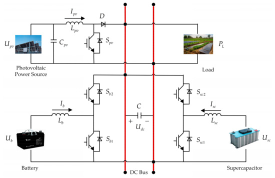
Figure 2.
DC microgrid topology.
The state-space equations of the hybrid energy storage system are given by:
In the model of this system, the input variables include the terminal voltage of the photovoltaic side, DC load, bus-side voltage, and the duty cycle of the switches, which directly affect the operation of the system. The output variables include the terminal voltage and inductor current through the battery, supercapacitor, and photovoltaic sides, as well as the filtering capacitor. These output variables reflect the system’s operational status and the energy conversion process.
2.2. Second-Order Active Disturbance Rejection Controller Design
Due to the inability to establish an accurate mathematical model for the hybrid energy storage system, combined with the randomness and volatility of the system, the performance of the PI control is poor. To enhance the control of the system’s bus voltage, linear active disturbance rejection control (LADRC) is introduced to improve the system’s disturbance rejection capability. The dynamic behavior of the system is described through state variables, providing a mathematical representation of the system’s evolution over time. When certain state variables cannot be directly measured, an observer is used to estimate these unmeasurable state variables, ensuring an accurate estimation of the system’s state.
Generally, the design of a second-order system is as follows:
where is the system input, is the system output, is the external disturbance, and represents the system parameters, and is the system gain. Both and , and are unknown, with the condition .
Let represent the total disturbance of the system. Then, Equation (2) can be simplified as
For any feasible solution of a single-input–single-output system, the generalized disturbance is uniformly bounded, and its derivative with respect to time is also bounded. and represents the generalized disturbance.
According to the design criteria of the linear extended state observer (LESO), defining the state variables and , and extend the disturbance term into a new system state variable . is a column vector composed of , , and . The system state equations can then be written as
The LESO established based on Equation (3) is as follows:
where , , and are the estimated values of the state variables of the LESO; , , and are the observer gain matrices to be designed. By configuring the observer parameters, the estimated state variables , , and can be made to approach the true values of the state variables , , and , respectively, achieving error-free estimation within a certain period of time.
By configuring the poles of the characteristic equation of the observer gain at , the following equation is obtained:
where represents the natural frequency of the observer design.
Expanding Equation (6) yields the LESO gain as follows:
By using the LESO to observe the system state variables in real-time, the total disturbance estimate is obtained. Based on the concept of active disturbance rejection, a disturbance compensation loop is designed to eliminate the disturbance, thereby making the system with uncertain disturbances equivalent to an integral-series system. The design of the disturbance compensation loop is as follows:
Substituting the in Equation (3) with theright-hand side of Equation (8) and ignoring the estimation errors, we obtain
By inputting the observed values of the state variables into the PD controller, the control law is obtained as follows:
where is the system input reference value, and and are the controller gains to be designed.
By substituting Equation (10) into Equation (9) and performing the necessary simplifications, the input–output relationship of the system is derived as follows:
Taking the Laplace transform of Equation (11), the closed-loop transfer function of the input–output system is obtained as follows:
By placing all the poles of the closed-loop transfer function at , we obtain
where represents the bandwidth of the controller. After applying the bandwidth method in linear active disturbance rejection, the observer parameters depend solely on , and the controller parameters depend solely on , significantly simplifying the parameter tuning process. By adjusting the two bandwidths, the entire control process can be achieved.
The bandwidth of the controlled object observer and the controller follows = 3∼5, as shown in the second-order linear active disturbance rejection control diagram in Figure 3.
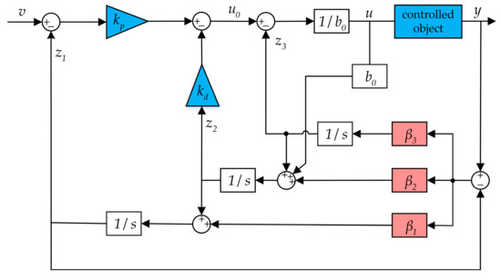
Figure 3.
Structure diagram of active disturbance rejection control.
3. Improved Sliding-Mode Active Disturbance Rejection Control
3.1. Sliding-Mode Active Disturbance Rejection Control
Second-order linear active disturbance rejection uses a linear observer to estimate the total disturbance of the system in real time, and the controller is designed to compensate and eliminate the disturbance. However, the controller uses PD control, which, although reduces the difficulty of parameter tuning, results in poor compensation accuracy and response speed. To improve the system’s disturbance compensation capability, sliding-mode control is introduced into the active disturbance rejection controller, replacing the original PD controller to enhance the system’s control performance.
Based on the aforementioned observer design principles, the LESO is given as
where represents the observer tracking error.
The system bus voltage error variable is defined as
where represents the reference bus voltage.
Taking the derivative of Equation (15) and plugging Equation (14) into it, the differential of with respect to is obtained as
Taking the derivative of Equation (16) and plugging Equation (14) into it, the result is obtained as
Design the sliding-mode surface as
where .
Design the sliding-mode reaching law [28] as
where and are both greater than zero.
Taking the derivative of Equation (18) and plugging Equations (16) and (17) into it, the result is obtained as
By combining Equation (19) with Equation (20) and simplifying, the control rate is obtained as
The original system is simplified to a series connection of two integrators as follows:
where .
The schematic of the sliding-mode active disturbance rejection control is shown in Figure 4.
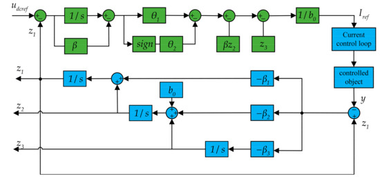
Figure 4.
Structure diagram of sliding-mode active disturbance rejection control.
In traditional sliding-mode active disturbance rejection control, a single observer fails to provide accurate estimates in the presence of complex disturbances, leading to degraded system performance. Additionally, the convergence speed of traditional methods is slow, which may result in system response lag, thus affecting the efficiency and stability of the energy storage system. To address this, this study proposes improved sliding-mode active disturbance rejection control to enhance the disturbance estimation capability and response speed of the observer.
3.2. Cascade Extended State Observer Design
The hybrid energy storage system exchanges power with the DC bus through a bidirectional converter, making it a typical second-order system. The control objective is the stabilization of the bus voltage . To achieve this, a voltage loop cascade observer is designed to enhance the ability to observe unknown disturbances and system power fluctuations.
The system state variables are the actual bus voltage , its derivative, and the total system disturbance . Therefore, the state variables of the voltage loop can be expressed as
According to the cascade observer design, the first-level observer of the voltage loop is denoted as LESO1, and the second-level observer is denoted as LESO2. Similar to the traditional LESO, the input to LESO1 consists of the control signal and the output signal of the controlled system. Based on Equation (23), LESO1 is designed as
where , , and are the state estimates of , , and , respectively; is the tracking error of the DC bus voltage for LESO1; and , , and are the gain to be designed for LESO1.
In the construction of LESO2, the initial estimate of the total disturbance is treated as the known part of LESO2. Therefore, Equation (24) can be reconstructed as
where , , and are the state estimate of , , and ; is the tracking error of the DC bus voltage for LESO1; and , , and are the gain to be designed for LESO2.
To simplify the parameter tuning, the observer gains for the two LESOs are designed as
where represents the bandwidth of the voltage loop cascaded observer.
By synthesizing the real-time observations of and , the total disturbance is reconstructed. If is the designed control rate, the system’s control signal is:
By cascading two linear observers, the disturbance estimation capability is enhanced. The estimated total disturbance is then fed into the designed controller for compensation and elimination, further improving the system’s control performance. The block diagram of the cascaded observer control is shown in Figure 5, where represents the reference value of the bus voltage.
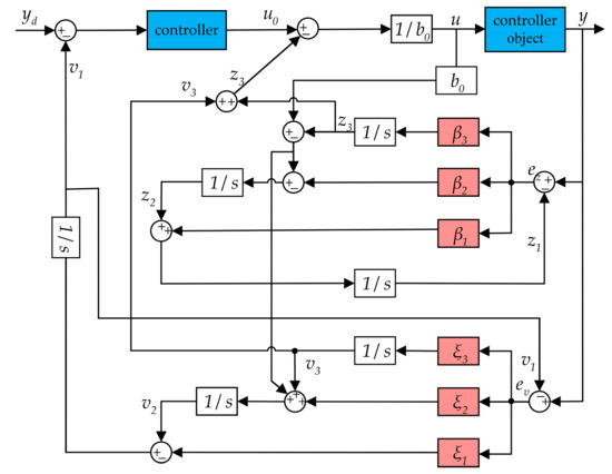
Figure 5.
Block diagram of cascaded observer structure.
3.3. Design of Non-Singular Fast Terminal Sliding-Mode Controller
Traditional sliding-mode control uses a linear sliding surface, which only achieves asymptotic convergence at slow convergence speed. Terminal sliding-mode control employs a nonlinear sliding surface, enabling finite-time convergence and improving convergence speed. However, it is subject to singularity issues, which limit its practical application in engineering. Non-singular fast terminal sliding-mode control (NFTSMC) not only achieves finite-time convergence to a stable value but also resolves the singularity problem. Therefore, in this section, NFTSMC is used to replace the PD control in active disturbance rejection control.
The bus voltage tracking error is defined as
The dynamic characteristics of the error variation over time: taking the derivative of yields:
To continue the analysis of the error dynamics, plugging Equation (25) into Equation (29) and differentiating give
To ensure finite-time convergence of the sliding surface, reduce chattering, and avoid singularity issues, the non-singular fast terminal sliding surface is designed as follows:
where , , , , .
Taking the derivative gives
Considering its feedback on the system’s error, error rate, and other system states, it enables the system to quickly and accurately reach the sliding surface and slide along it, the controller is designed as
where represents the equivalent controller, and represents the robust controller.
To improve the system’s convergence and robustness, the equivalent controller and robust controller are designed; plugging Equation (30) into Equation (32) and simplifying determine the equivalent controller as
The robust controller is designed as
where , , , .
Combining the above controllers, the complete NFTSMC controller is given as
The block diagram of the voltage loop ISMADRC system is shown in Figure 6.
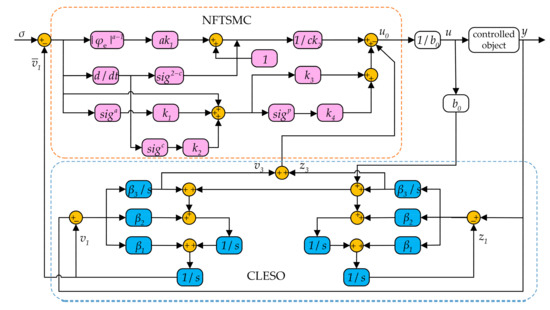
Figure 6.
Block diagram of improved sliding-mode active disturbance rejection control.
Figure 6 presents the control algorithm flowchart of ISMLADRC, which is developed through the integration of NFTSMC and CLESO. NFTSMC enhances convergence speed and eliminates singularity issues, while CLESO optimizes the control law and error estimation to improve system robustness. The integration of these methods enhances ISMLADRC disturbance rejection capability and stability under dynamic conditions.
4. Results
To verify the feasibility of the proposed ISMLADRC strategy, a photovoltaic-storage DC microgrid hybrid energy storage model is built on the simulation platform, with the system model parameters remaining unchanged. This model is compared with the proposed PI and LADRC strategies. The initial conditions of the system are set as shown in Table 2.
Table 2.
Parameters of the simulation system.
4.1. Photovoltaic Power Generation System
To improve the efficiency of photovoltaic power generation and ensure that the system operates at the maximum power point, the photovoltaic cells must operate in maximum power point tracking (MPPT) mode. In this paper, the incremental conductance (INC) method is adopted as the MPPT control strategy, and its performance is verified through simulation. Compared to traditional methods, INC can more effectively reduce the system’s volatility and dynamic response time. Moreover, the INC method maintains good performance in environments with significant variations in solar irradiance and temperature, avoiding excessive perturbation issues, thereby improving system stability and tracking accuracy. This method is based on the condition that the derivative of the photovoltaic cell output power with respect to voltage is zero at the maximum power point ; at this point,
The detailed flow of the algorithm is shown in Figure 7.
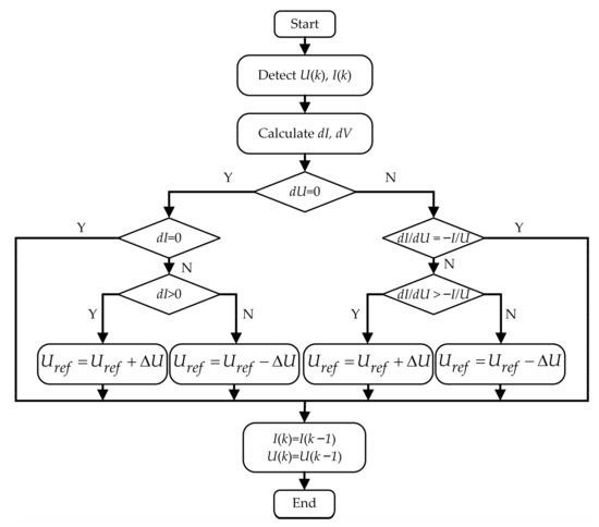
Figure 7.
Block diagram of the INC algorithm.
To verify the performance of the INC method in terms of maximum power tracking efficiency and stability, tests were conducted under both constant and sudden changes in solar irradiance. The test conditions are shown in Table 3, and the photovoltaic output waveform is shown in Figure 8.
Table 3.
Operating conditions.
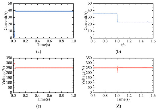
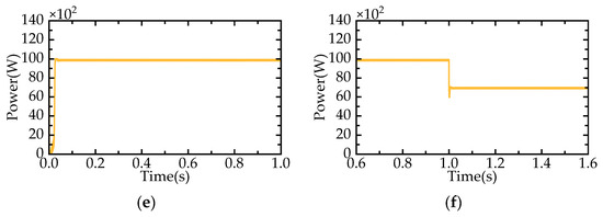
Figure 8.
Photovoltaic module output model diagram: (a) condition 1 maximum power point current; (b) condition 2 maximum power point current; (c) condition 1 maximum power point voltage; (d) condition 2 maximum power point voltage; (e) condition 1 maximum power point power; (f) condition 2 maximum power point power.
Figure 8 can be observed that the Incremental Conductance method successfully reaches the maximum power point and maintains operation at this point with minimal oscillation. When there is a sudden change in solar irradiance, the photovoltaic system is able to quickly adjust and operate at the new maximum power point. Therefore, the Incremental Conductance method will be chosen as the control strategy for the photovoltaic system in this paper.
4.2. Normal Conditions
The system temperature is set to 25 °C, with a constant load of 3000 W, with a constant solar irradiance of S = 1000 W/m2, and the initial battery SOC is 50%. When the photovoltaic power generation is lower than the load demand, the hybrid energy storage system will provide the insufficient power to the load. The waveform of the DC-side voltage of the microgrid is shown in Figure 9.
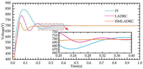
Figure 9.
DC-side voltage waveform under normal conditions.
As shown in Figure 9, a comparison of the three control strategies reveals that the proposed improved control strategy has the fastest response time from startup to the first stabilization of the DC bus voltage. Compared to traditional control methods, the recovery time is faster, and the overshoot is also reduced, with the maximum fluctuation value decreased to around 25 V. Figure 10 below shows the power output curves of the supercapacitor and the battery under the ISMLADRC strategy for this operating condition.
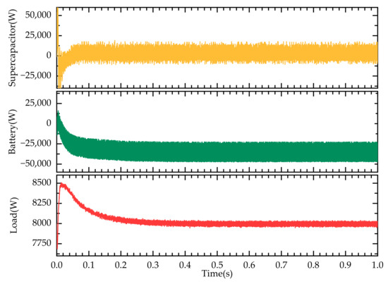
Figure 10.
Power exchange diagram under normal conditions: supercapacitor output power; battery output power; load power.
In the constructed hybrid system, the photovoltaic power generation unit achieves a rated output power of 10,000 W, of which 8000 W is directly supplied to the load to ensure a stable power supply to the load. The remaining 2000 W of electrical energy is absorbed and stored by the hybrid energy storage unit through the power scheduling system. By storing the excess power, this avoids the waste of photovoltaic generation and provides a backup power source for load peaks or insufficient photovoltaic generation. The SOC curves of the supercapacitor and battery during this process are shown in Figure 11.
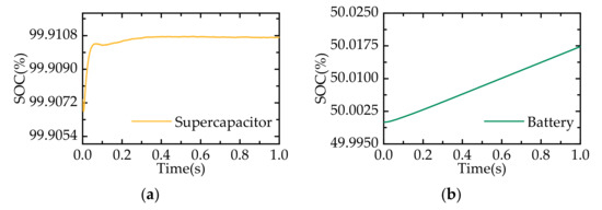
Figure 11.
SOC curves under normal conditions: (a) supercapacitor; (b) battery.
4.3. Photovoltaic Fluctuations Conditions
The load is kept running at a constant power of 10,000 W. At 1 s, the solar irradiance suddenly drops from 1000 W/m2 to 700 W/m2. The photovoltaic output power becomes less than the load demand, and the hybrid energy storage unit compensates for the power deficit, maintaining the DC bus voltage constant. For the photovoltaic power fluctuations, the three control strategies are compared and analyzed under the condition of unchanged circuit parameters. The DC-side voltage waveform under varying solar irradiance is shown in Figure 12.
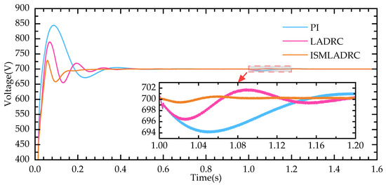
Figure 12.
DC-side voltage waveform under photovoltaic fluctuation conditions.
As shown in Figure 12, when the photovoltaic output is less than the load demand, the bus voltage drops, and the energy storage unit releases power to stabilize the bus voltage. Under ISMLADRC, the bus voltage fluctuation is minimal and reaches stability after 40 ms. Comparing the simulation results, it can be observed that the ISMLADRC strategy results in smaller overshoot and faster recovery of the bus voltage during photovoltaic power fluctuations. The power output curves of the supercapacitor and battery are shown in Figure 13.
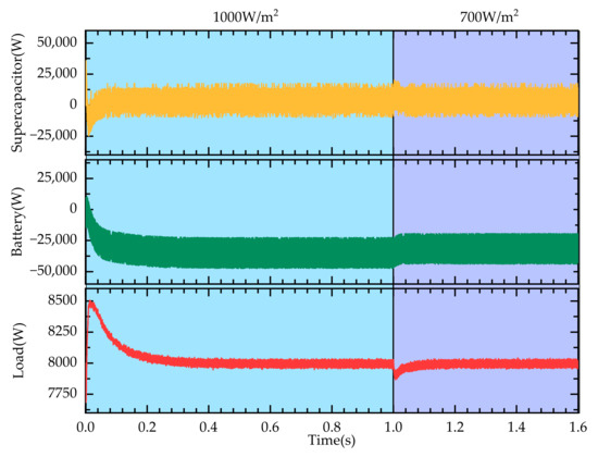
Figure 13.
Power exchange diagram under photovoltaic fluctuation conditions: supercapacitor output power; battery output power; load power.
When the photovoltaic power changes rapidly, the supercapacitor can respond instantaneously to compensate or absorb power, while the battery can provide stable compensation or absorb power in the steady state. This indicates that the system has the ability to perform fast and effective power distribution based on the differences in high- and low-frequency components. The SOC curves are shown in Figure 14.
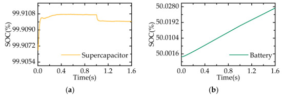
Figure 14.
SOC curves under photovoltaic fluctuation conditions: (a) supercapacitor; (b) battery.
4.4. Load Fluctuations Conditions
The solar irradiance is kept constant at 1000 W/m2, and the system operates stably until 0.6 s, when the DC load suddenly increases from 8000 W to 32,000 W, causing a temporary voltage drop of the bus, which then recovers to the reference value. Between 0.9 s and 1.2 s, the DC load first decreases to 24,000 W and then increases to 28,000 W, causing the bus voltage to temporarily rise and then drop. With the assistance of the hybrid energy storage system, the voltage is restored and maintained stable, as shown in Figure 15.
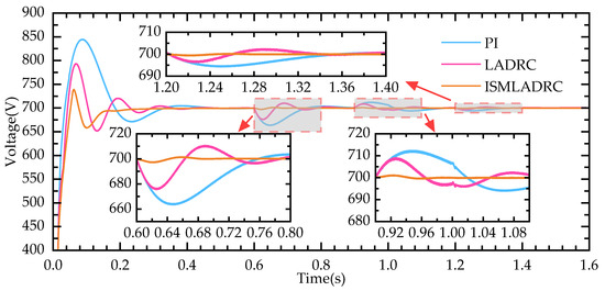
Figure 15.
DC-side voltage waveforms under load fluctuation conditions.
When the system operates to 0.6 s and the load suddenly increases, the DC bus voltage fluctuation peaks are larger under traditional PI and LADRC strategies, with a recovery time of approximately 0.2 s. Under the ISMLADRC strategy, the fluctuation peaks of the DC bus voltage are significantly reduced, and the recovery time to steady state is shortened to 0.08 s. Moreover, during the continuous load variations at 0.9 s and 1.2 s, the ISMLADRC strategy shows a reduction in both the fluctuation amplitude and steady-state recovery time, outperforming the other two control methods. The power output curves of the supercapacitor and battery are shown in Figure 16, and the SOC curves are shown in Figure 17.
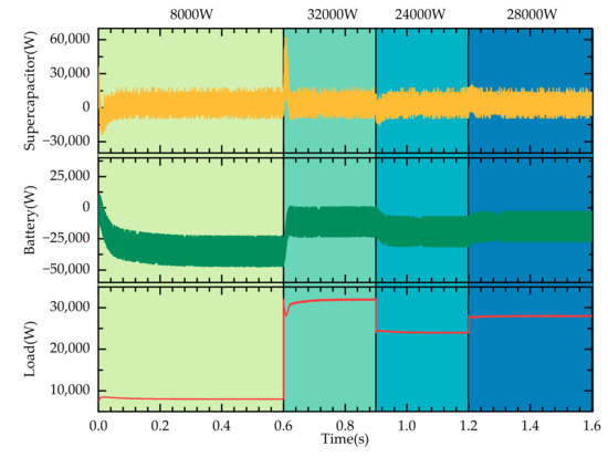
Figure 16.
Power exchange diagram under load fluctuation conditions: supercapacitor output power; battery output power; load power.
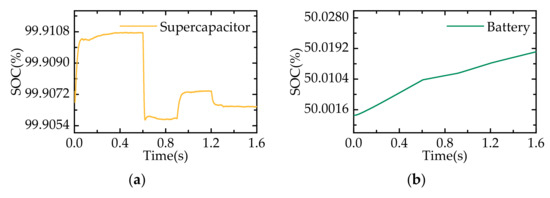
Figure 17.
SOC curves under load fluctuation conditions: (a) supercapacitor; (b) battery.
Based on the experimental results, the ISMLADRC method proposed in this study demonstrates significant robustness and superiority under dynamic conditions such as fluctuations in solar irradiance and load variations. Initially, the performance of the photovoltaic power generation system was tested. Subsequently, the microgrid DC-side voltage, power flow, and the SOC curves of the energy storage system were analyzed, with investigations conducted under normal operating conditions, photovoltaic power fluctuations, and load variations. Through simulation and experimental validation under different operating conditions, the results show that this method effectively suppresses system output fluctuations and maintains good stability under rapidly changing external disturbances. In practical applications, the method exhibits strong adaptability and reliability.
5. Conclusions
This paper proposes a photovoltaic-storage DC microgrid solution to meet the electricity supply needs of remote areas, with a particular focus on providing stable power support to agricultural facilities and greenhouses. Due to significant fluctuations in solar irradiance and load, traditional power supply methods often struggle to meet demand. By introducing a hybrid energy storage system, optimizing microgrid power compensation, and ensuring the stability of the power supply to agricultural greenhouses, the proposed solution effectively maintains bus voltage stability. The ISMLADRC strategy designed in this paper not only improves the response speed of the microgrid control system but also enhances the system’s adaptability to agricultural facilities in complex environments.
The proposed approach effectively addresses the instability of the power supply to agricultural facilities, ensuring the continuous and stable operation of greenhouses and irrigation systems. Additionally, by reducing energy costs, it decreases reliance on external grids and enhances the system’s ability to adapt to load variations and environmental fluctuations. The system’s high robustness and efficiency ensure a reliable power supply for crop production in remote areas, while improving the level of automation and intelligence in agricultural production and promoting the sustainable development of green agriculture.
Author Contributions
Conceptualization, B.H. and K.S.; methodology, B.H.; software, K.S.; validation, T.Z. and Z.L.; formal analysis, T.Z. and H.L.; investigation, D.J. and R.W.; resources, D.J. and R.W.; data curation, B.H. and K.S.; writing—original draft preparation, B.H. and K.S.; writing—review and editing, Z.L. and H.L.; visualization, T.Z.; supervision, B.H.; project administration, B.H.; funding acquisition, B.H. All authors have read and agreed to the published version of the manuscript.
Funding
This research was funded by the National Natural Science Foundation of China under the grant number 61601140 and the Postdoctoral Initiation Foundation of Heilongjiang under the grant number 68641400.
Institutional Review Board Statement
Not applicable.
Data Availability Statement
The original contributions presented in this study are included in this article. Further inquiries can be directed to the corresponding author.
Acknowledgments
We are also very grateful to the anonymous reviewers for their valuable comments and suggestions for the improvement of this paper.
Conflicts of Interest
The authors declare no conflicts of interest.
Abbreviations
The following abbreviations are used in this manuscript:
| ISMLADRC | Improved sliding-mode linear active disturbance rejection control |
| HESS | Hybrid energy storage system |
| SOC | State of charge |
| SOH | State of health |
| VSM | Virtual synchronous machine |
| CVCF | Constant voltage constant frequency |
| PI | Proportional–integral |
| ADRC | Active disturbance rejection control |
| ESO | Extended state observer |
| CLESO | Cascaded linear extended state observer |
| SMC | Sliding-mode control |
| PD | Proportional–derivative |
| PV | Photovoltaic |
| LADRC | Linear active disturbance rejection control |
| LESO | Linear extended state observer |
| NFTSMC | Non-singular fast terminal sliding-mode control |
| MPPT | Maximum power point tracking |
| INC | Incremental conductance |
References
- AI-Shetwi, A.Q. Sustainable development of renewable energy integrated power sector: Trends, environmental impacts, and recent challenges. Sci. Total Environ. 2022, 822, 153645. [Google Scholar]
- Farghali, M.; Osman, A.I.; Mohamed, I.M.; Chen, Z.; Chen, L.; Ihara, I.; Rooney, D.W. Strategies to save energy in the context of the energy crisis: A review. Environ. Chem. Lett. 2023, 21, 2003–2039. [Google Scholar]
- Chen, X.H.; Tee, K.; Elnahass, M.; Ahmed, R. Assessing the environmental impacts of renewable energy sources: A case study on air pollution and carbon emissions in China. J. Environ. Manag. 2023, 345, 118525. [Google Scholar]
- García Vera, Y.E.; Dufo-López, R.; Bernal-Agustín, J.L. Energy management in microgrids with renewable energy sources: A literature review. Appl. Sci. 2019, 9, 3854. [Google Scholar] [CrossRef]
- Sandelic, M.; Peyghami, S.; Sangwongwanich, A.; Blaabjerg, F. Reliability aspects in microgrid design and planning: Status and power electronics-induced challenges. Renew. Sustain. Energy Rev. 2022, 159, 112127. [Google Scholar]
- Fukaume, S.; Nagasaki, Y.; Tsuda, M. Stable power supply of an independent power source for a remote island using a Hybrid Energy Storage System composed of electric and hydrogen energy storage systems. Int. J. Hydrogen Energy 2022, 47, 13887–13899. [Google Scholar]
- Jin, J.X.; Zhang, T.L.; Yang, R.H.; Wang, J.; Mu, S.; Li, H. Hierarchical cooperative control strategy of distributed hybrid energy storage system in an island direct current microgrid. J. Energy Storage 2023, 57, 106205. [Google Scholar]
- Hall, P.J.; Bain, E.J. Energy-storage technologies and electricity generation. Energy Policy 2008, 36, 4352–4355. [Google Scholar]
- Hajiaghasi, S.; Salemnia, A.; Hamzeh, M. Hybrid energy storage system for microgrids applications: A review. J. Energy Storage 2019, 21, 543–570. [Google Scholar]
- Elmorshedy, M.F.; Subramaniam, U.; Mohamed Ali, J.S.; Almakhles, D. Energy management of hybrid DC microgrid with different levels of DC bus voltage for various load types. Energies 2023, 16, 5438. [Google Scholar] [CrossRef]
- Arévalo, P.; Ochoa-Correa, D.; Villa-Ávila, E. Towards Energy Efficiency: Innovations in High-Frequency Converters for Renewable Energy Systems and Electric Vehicles. Vehicles 2024, 7, 1. [Google Scholar] [CrossRef]
- Gopi, C.V.M.; Ramesh, R. Review of battery-supercapacitor hybrid energy storage systems for electric vehicles. Results Eng. 2024, 24, 103598. [Google Scholar] [CrossRef]
- Essa, M.E.S.M.; Ali, M.F.; El-kholy, E.E.; Amer, M.; Elsisi, M.; Sajjad, U.; Awad, H.E.S. Improving Micro-Grid Management: A Review of Integration of Supercapacitor across Different Operating Modes. Heliyon 2025, 11, e42178. [Google Scholar] [CrossRef] [PubMed]
- Jeyaraj, T.; Ponnusamy, A.; Selvaraj, D. Hybrid renewable energy systems stability analysis through future advancement technique: A review. Appl. Energy 2025, 383, 125355. [Google Scholar] [CrossRef]
- Liu, Z.; Luo, J.; Sun, Y.; Zhang, X.; Yan, Z. Advancing urban sustainability: Integrating renewable energy for accelerated zero-carbon community transitions. Front. Energy Res. 2024, 12, 1523257. [Google Scholar] [CrossRef]
- Rao, S.P.; Ranganathan, P.; Tomomewo, O.S. Hybrid Energy Storage Systems for Renewable Energy Integration: An Overview. In Proceedings of the 2024 56th North American Power Symposium (NAPS), El Paso, TX, USA, 13–15 October 2024; pp. 1–8. [Google Scholar]
- Azam, T.; Khalid, M.S.; Wu, Z.S. Lewis acid molten salt synthesis of 2D MXenes with fine-tuned surface terminations for energy storage and conversion. Mater. Today 2025, 78, 123–135. [Google Scholar] [CrossRef]
- Wang, X.; Wen, F. Optimal Planning and Operation in RES-Rich Power Systems under Electricity and Carbon Emission Market Environment. IEEE Trans. Sustain. Energy 2024, 15, 987–1001. [Google Scholar]
- Hirose, T.; Matsuo, H. Standalone hybrid wind-solar power generation system applying dump power control without dump load. IEEE Trans. Ind. Electron. 2011, 59, 988–997. [Google Scholar] [CrossRef]
- Sekhri, E.; Ibrahim, M.; Zequera, R.G.; Rassõlkin, A. Electric and Hybrid Vehicles: From Smart Energy Storage Systems to Mechanical Transmission. In Smart Electric and Hybrid Vehicles: Advancements in Materials, Design, Technologies, and Modeling; John Wiley & Sons, Inc.: Hoboken, NJ, USA, 2025; pp. 71–126. [Google Scholar] [CrossRef]
- Billanes, J.D.; Jørgensen, B.N.; Ma, Z. A Framework for Resilient Community Microgrids: Review of Operational Strategies and Performance Metrics. Energies 2025, 18, 405. [Google Scholar] [CrossRef]
- Çelik, D.; Khan, M.A.; Khosravi, N.; Waseem, M.; Ahmed, H. A review of energy storage systems for facilitating large-scale EV charger integration in electric power grid. J. Energy Storage 2025, 112, 115496. [Google Scholar] [CrossRef]
- Blanch-Fortuna, A.; Zambrano-Prada, D.; López-Santos, O.; Aroudi, A.E.; Vázquez-Seisdedos, L.; Martinez-Salamero, L. Hierarchical Control of Power Distribution in the Hybrid Energy Storage System of an Ultrafast Charging Station for Electric Vehicles. Energies 2024, 17, 1393. [Google Scholar] [CrossRef]
- Liu, X.; Chen, J.; Suo, Y.; Song, X.; Ju, Y. Active Disturbance Rejection Control Combined with Improved Model Predictive Control for Large-Capacity Hybrid Energy Storage Systems in DC Microgrids. Appl. Sci. 2024, 14, 8617. [Google Scholar] [CrossRef]
- Li, H.; Yao, T.; Zhang, X.; Bu, F.; Weng, L. Hybrid energy storage management strategy for electric propulsion aircraft based on three-step power distribution. World Electr. Veh. J. 2021, 12, 209. [Google Scholar] [CrossRef]
- Wang, C.; Lei, Z.; Huo, H.; Yao, G. Transient Stability Control Strategy Based on Uncertainty Quantification for Disturbances in Hybrid Energy Storage Microgrids. Appl. Sci. 2024, 14, 10212. [Google Scholar] [CrossRef]
- Peng, Z.; Cui, K.; Li, H.; Gu, N.; Liu, L.; Wang, D. Model-free antidisturbance autopilot design for autonomous surface vehicles with hardware-in-the-loop experiments. IEEE Trans. Ind. Inform. 2023, 20, 2387–2396. [Google Scholar]
- Fallaha, C.J.; Saad, M.; Kanaan, H.Y.; Al-Haddad, K. Sliding-mode robot control with exponential reaching law. IEEE Trans. Ind. Electron. 2010, 58, 600–610. [Google Scholar]
Disclaimer/Publisher’s Note: The statements, opinions and data contained in all publications are solely those of the individual author(s) and contributor(s) and not of MDPI and/or the editor(s). MDPI and/or the editor(s) disclaim responsibility for any injury to people or property resulting from any ideas, methods, instructions or products referred to in the content. |
© 2025 by the authors. Licensee MDPI, Basel, Switzerland. This article is an open access article distributed under the terms and conditions of the Creative Commons Attribution (CC BY) license (https://creativecommons.org/licenses/by/4.0/).