4.1. Study on the Single-Seed Adsorption Characteristics of Narrow Elongated Suction Holes
(1) Effect of the Suction Hole Width on the Adsorption Force Acting on Near-Wall Particles
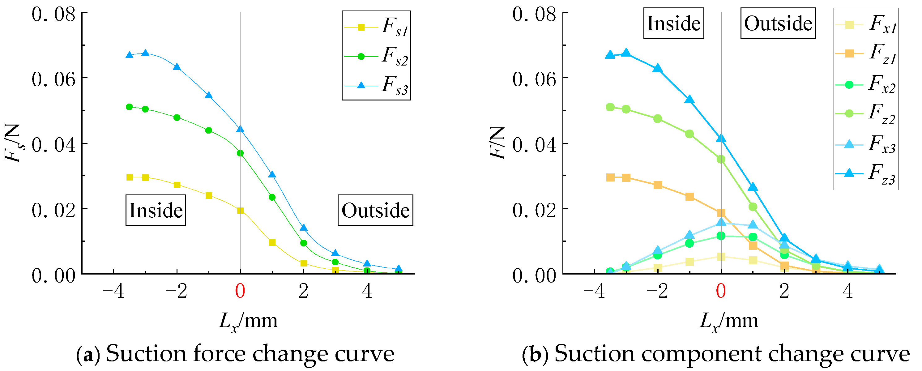
The force curves of the particles moving along the x-axis under different suction hole widths are shown in
Figure 7, while those along the y-axis are shown in
Figure 8.
When a particle moves along the long side of the suction hole (x-axis), the adsorption force
Fs is significantly affected by
Kb, as illustrated in
Figure 7. An increase in
Kb expands the suction hole area, thereby enhancing the adsorption force acting on the particle.
Figure 7a shows that when
Kb = 3 mm, the peak adsorption force is 1.32 times that at
Kb = 2 mm, while at
Kb = 2 mm, the peak adsorption force is 1.72 times that at
Kb = 1 mm. This indicates that variations in
Kb significantly affect the magnitude of the adsorption force. As the particle moves towards the suction hole edge (with
Lx approaching 0), the adsorption force gradually decreases. At
Kb = 3 mm, the adsorption force at the boundary of the long side (
Lx = 0) is reduced by 34% compared to that at the hole center, while for
Kb = 2 mm and
Kb = 1 mm, the reduction is 27.7% and 34.24%, respectively. Outside the suction hole region, the adsorption force continues to decline at different rates for each width, with the decay rate slowing down when
Lx exceeds 2 mm. The ranking of
Lx values corresponding to zero adsorption force follows: 3 mm > 2 mm > 1 mm.
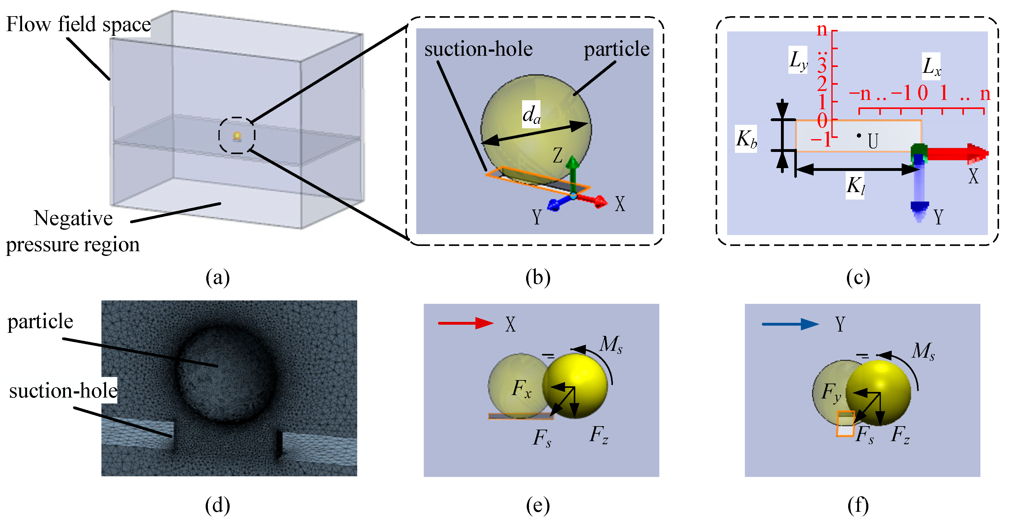
The flow field around the narrow elongated suction hole exhibits a semi-ellipsoidal shape. Due to symmetry, the y-component of the adsorption force (
Fy) is approximately zero when the particle moves along the x-axis. Thus, the total adsorption force
Fs can be decomposed into an x-axis component (
Fx) and a z-axis component (
Fz), as shown in
Figure 7b. When the particle is at the suction hole center (
U point), both
Fx and
Fy are nearly zero, making
Fs equal to
Fz. In
Figure 7a,b,
Fz closely follows
Fs in both magnitude and trend, making further analysis of
Fz unnecessary. However, as the particle moves away from the suction hole center,
Fx increases, reaching its maximum between 0.5 mm and 1 mm, though its value remains significantly lower than
Fz.
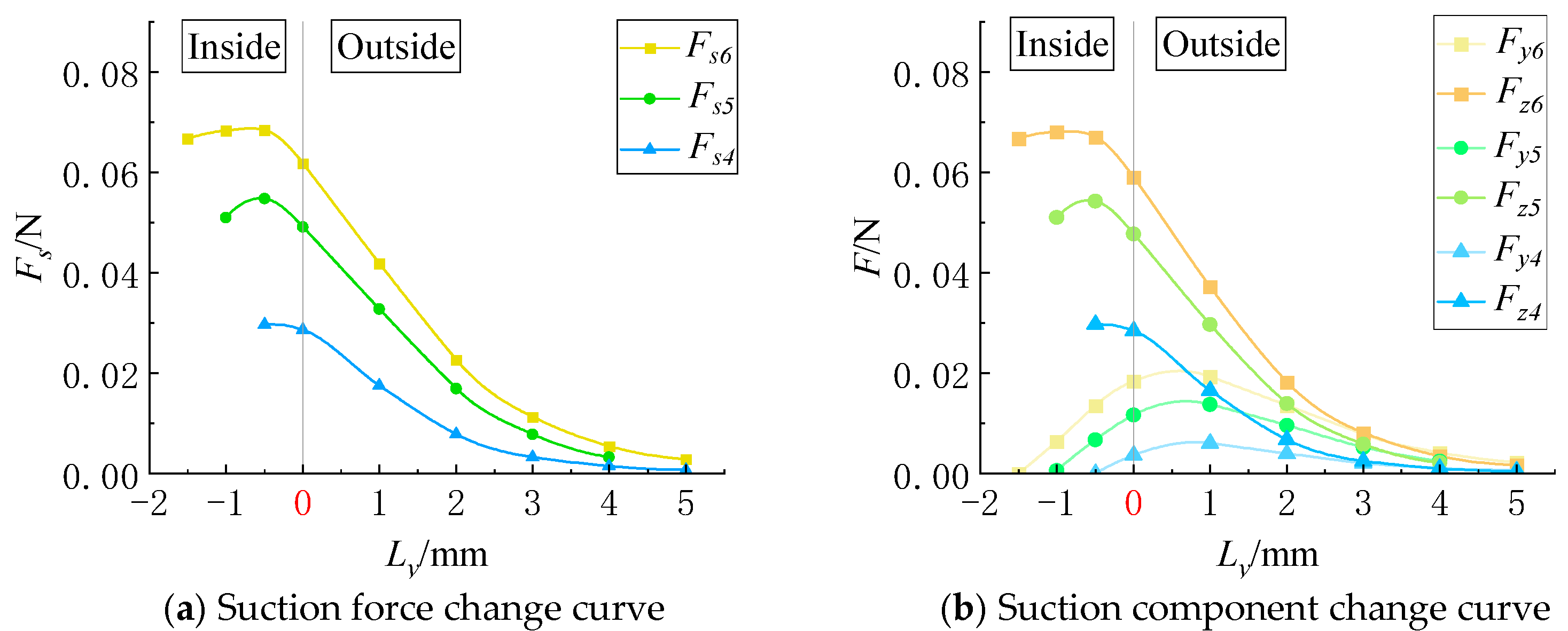
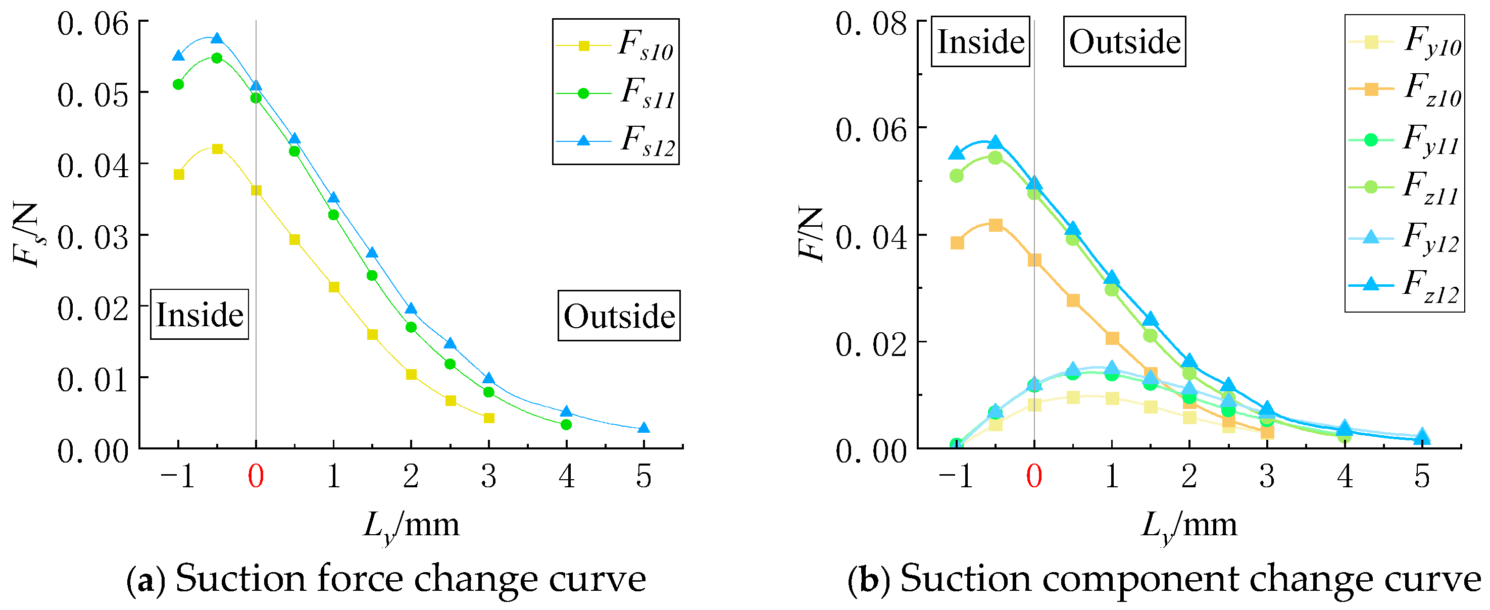
When the particle moves along the short side of the suction hole (y-axis), as shown in
Figure 8, the adsorption force
Fs varies slightly within the suction hole region. At
Kb = 3 mm, the adsorption force at the short-side boundary (
Ly = 0) decreases by 9.57% compared to its maximum value; for
Kb = 2 mm and
Kb = 1 mm, the reductions are 10.23% and 3.57%, respectively. When
Kb = 1 mm, the particle moves over a short distance within the suction hole, resulting in minimal variation in
Fs. For
Kb = 2 mm and
Kb = 3 mm, the
Fs curve exhibits a slight initial increase, followed by a decrease. This phenomenon occurs because at the suction hole center (
U point), the symmetrical flow field results in a near-zero y-axis force. As the particle moves, this symmetry is disrupted, increasing airflow differences on either side of the particle and causing a slight increase in
Fs, with a peak at
Ly = −0.5 mm. Outside the suction hole region, the force decay rate transitions from fast to slow, with the smallest suction force observed for the 1-mm-wide hole, which also reaches zero the fastest.
When the particle moves along the y-axis, the x-axis force (
Fx) is negligible and thus not analyzed. The force decomposition in
Figure 8b shows that
Fz closely follows
Fs. As the particle moves away from the symmetry center (
U point),
Fy increases before gradually decreasing beyond a certain distance, with the gradient of
Fy varying significantly with
Kb.
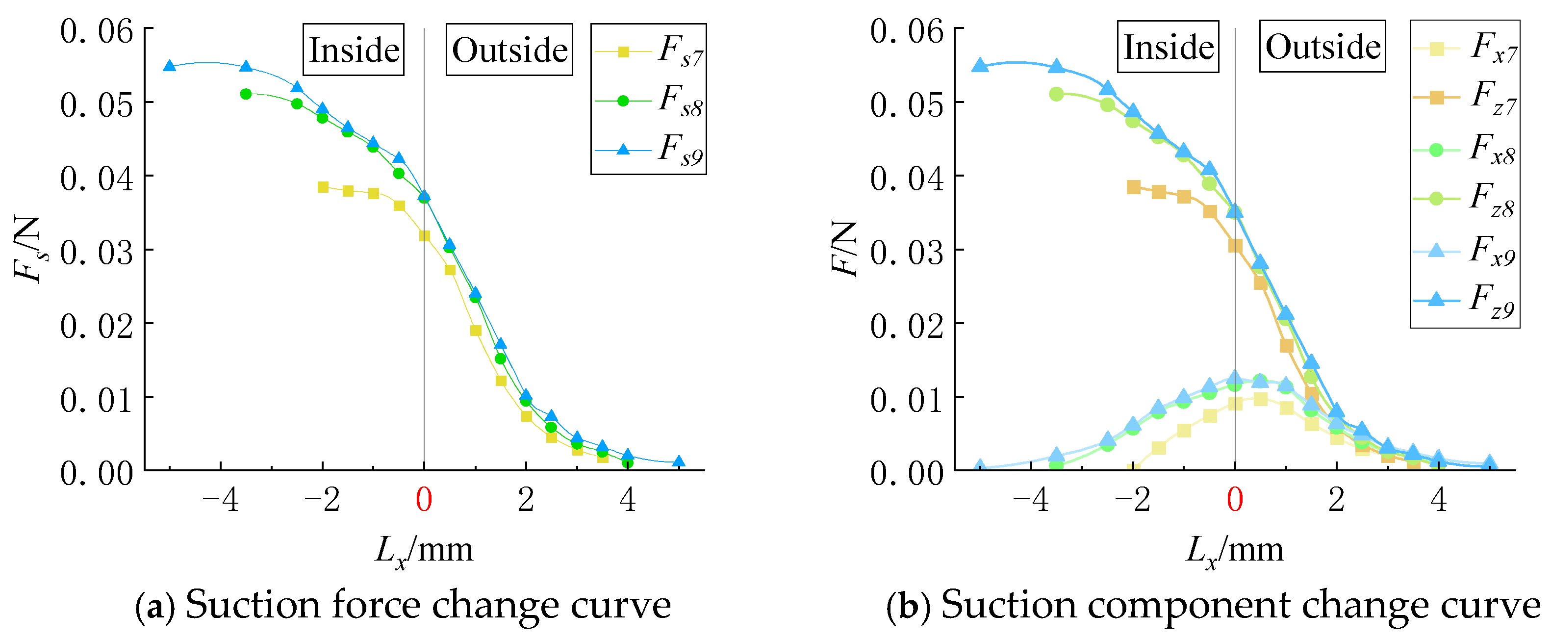
(2) Effect of the Suction Hole Length on the Adsorption Force Acting on Near-Wall Particles
The force curves for particle movement along the x-axis and y-axis under different suction hole lengths are shown in
Figure 9 and
Figure 10, respectively.
As shown in
Figure 9, when the particle moves along the long side of the suction hole (x-axis), the adsorption force
Fs varies significantly with
Kl. The order of adsorption force magnitudes corresponds to the order of suction hole lengths. When
Kl = 7 mm, the peak adsorption force is 1.33 times that at
Kl = 4 mm, whereas at
Kl = 10 mm, it is only 1.07 times that at
Kl = 7 mm. This suggests that when
Kl is smaller than
da, its variations significantly influence
Fs; however, beyond this threshold, further increasing
Kl has little additional impact. Within the suction hole region, the adsorption force decreases as the particle moves toward the edge (with
Lx approaching 0), but the decay rate is lower compared to that outside the suction hole region. At
Kl = 10 mm, the adsorption force at
Lx = 0 is reduced by 32.11% compared to that at the hole center; for
Kl = 7 mm and
Kl = 4 mm, the reductions are 27.7% and 17%, respectively. Outside the suction hole region, the adsorption forces on particles at the same relative positions are nearly identical across different
Kl values.
The flow field around the narrow elongated suction hole exhibits a semi-ellipsoidal shape. Due to symmetry, the y-component of the adsorption force (
Fy) remains nearly zero when the particle moves along the x-axis, allowing the force decomposition into
Fx and
FZ (
Figure 9b). As the particle moves from the suction hole center (
U point) to the edge,
Fx first increases and then decreases, peaking between 0.5 mm and 1 mm, while
FZ closely follows
FS.
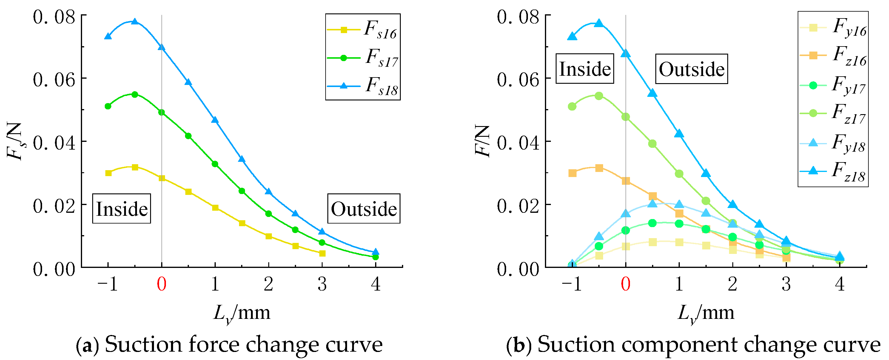
As shown in
Figure 10, when the particle moves along the short-edge direction of the suction hole (y-axis), the adsorption force
FS initially increases slightly within the suction hole region before decreasing. Specifically, when
Kl is 10 mm, the adsorption force at the short-edge boundary (
Ly = 0) decreases by 13.8% relative to the maximum adsorption force; when
Kl is 7 mm, the reduction is 10.23%; and when
Kl is 4 mm, the reduction is 11.44%. A shorter
Kb results in smaller variations in adsorption force within the suction hole region.
Outside the suction hole region, the adsorption force acting on the particle at the same relative position varies depending on the suction hole length. This indicates that in the y-axis direction, a 4-mm-long suction hole has a smaller effective capture range for near-wall particles than a 7-mm-long suction hole, while a 10-mm-long suction hole captures near-wall particles within a slightly larger range than the 7-mm-long suction hole.
Since the x-axis adsorption force
Fx was not analyzed in this section, only the force components
Fz and
Fs were considered, as illustrated in
Figure 10b. The magnitudes and variations of
Fz closely resemble those of
Fs. As the particle moves away from the symmetric center of the flow field (
U point),
Fy begins to increase, reaching a peak after a certain distance from the suction hole before decreasing. The semi-ellipsoidal nature of the airflow field within the narrow elongated suction hole leads to a shorter decay distance for the adsorption force when the particle moves along the minor axis (y-axis) compared to when it moves along the major axis (x-axis).
(3) Influence of Vacuum Level on Adsorption Force Acting on Near-Wall Particles
Under different vacuum levels, the force curves for particle movement along the x-axis and y-axis are shown in
Figure 11 and
Figure 12, respectively.
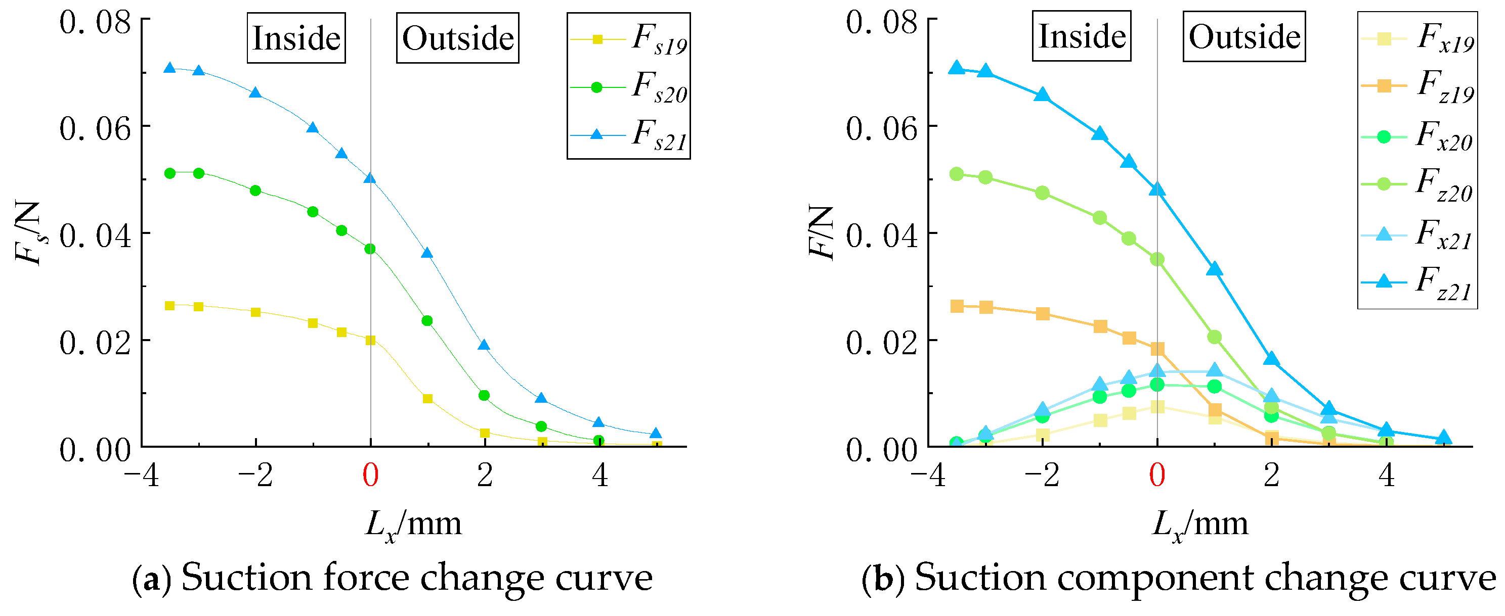
As illustrated in
Figure 11, when a particle moves along the long edge direction (x-axis) of the suction hole, the vacuum level
P significantly influences the adsorption force. The trends in adsorption force under the three vacuum levels are highly similar, but the force magnitudes at the same position vary considerably. When
P = 10 kPa, the peak adsorption force is 1.43 times that at
P = 7 kPa, while at
P = 7 kPa, it is 1.71 times that at
P = 4 kPa. The adsorption force gradually decreases as the particle moves from the suction hole center to the boundary. Specifically, at
P = 10 kPa, the adsorption force at the long-edge boundary decreases by 30.35% compared to the suction hole center; at
P = 7 kPa, the reduction is 27.71%; and at
P = 4 kPa, the reduction is 31.99%.
Outside the suction hole region, the force differences between the three vacuum levels gradually diminish. The force curve at P = 10 kPa exhibits the steepest decline, with the force approaching zero at a 4 mm distance from the short edge. At P = 4 kPa, the force curve declines the slowest, approaching zero at a 3 mm distance from the short edge.
Similar to the previous analysis, the adsorption force along the x-axis can be decomposed into
Fx and
Fz (
Figure 11b).
Fz closely resembles
Fs in magnitude and variation trend. As the particle moves away from the suction hole center,
Fx gradually increases, reaching a maximum between 0.5 mm and 1 mm. Since
Fx is significantly smaller than
Fz, the adsorption force in the z-axis plays a dominant role in restraining the particle within the suction hole.
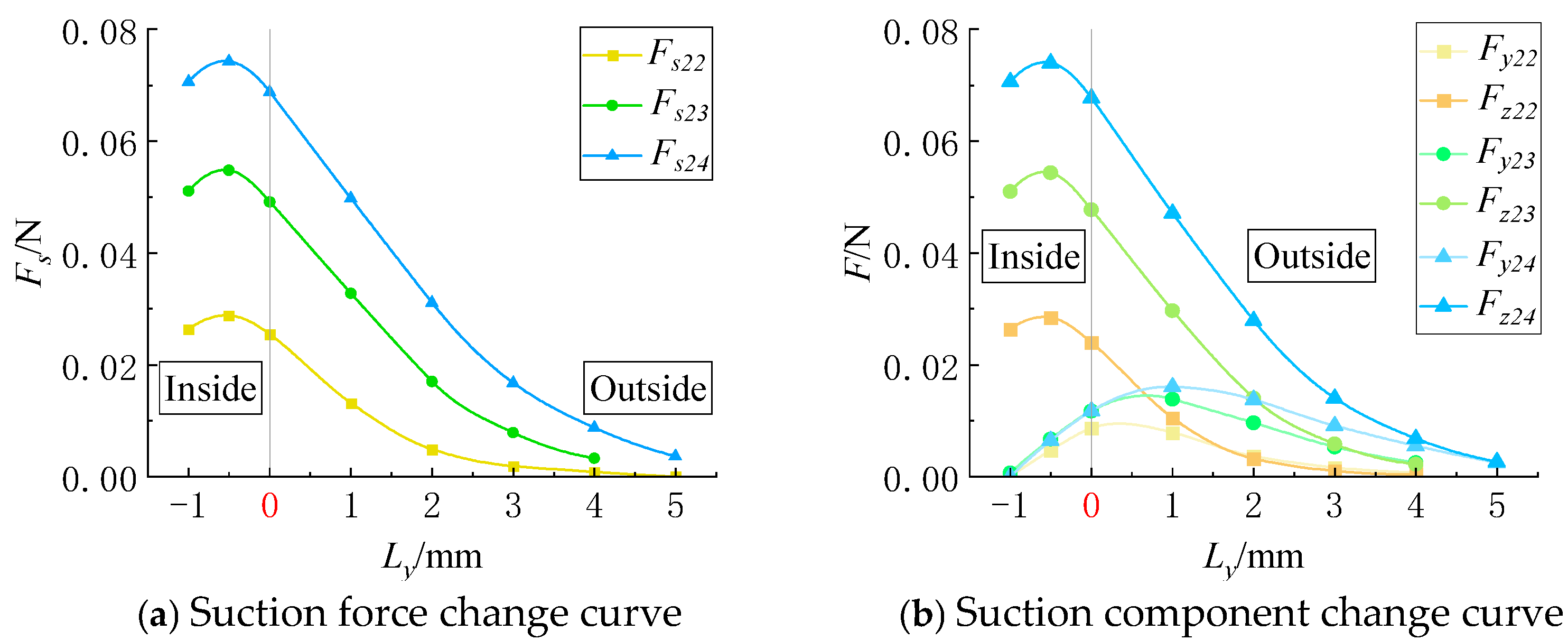
When the particle moves along the short-edge direction (y-axis) of the suction hole, all three vacuum levels exhibit a slight increase in adsorption force
Fs before decreasing (
Figure 12a), with a larger increase at higher
P values. Experimental results show that at
P = 10 kPa, the adsorption force at the short-edge boundary decreases by 10.79% relative to the peak force; at
P = 7 kPa, it decreases by 10.23%; and at
P = 4 kPa, it decreases by 10.35%.
Outside the suction hole region, the adsorption force at the same Ly position is positively correlated with P, indicating that the particle capture capability of the suction hole along the y-axis follows the order 10 kPa > 7 kPa > 4 kPa.
As shown in
Figure 12b, decomposing the adsorption force into
Fy and
Fz reveals that
Fz closely matches
Fs in magnitude and trend. When the particle moves away from the symmetric center of the flow field,
Fy begins to increase, reaching a maximum after a certain distance from the suction hole before decreasing.
(4) Influence of Particle Diameter on the Suction Force Acting on Near-Wall Particles
The force curves for particles moving along the x-axis under different particle diameters are shown in
Figure 13, while those for particles moving along the y-axis are presented in
Figure 14.
As illustrated in
Figure 13, the suction force
Fs acting on a particle varies as it moves along the long edge of the suction hole (x-axis direction). Differences in particle diameter
da result in significant variations in the suction force. When
da = 10 mm, the peak suction force is 1.38 times that when
da = 7 mm, while the peak suction force for
da = 7 mm is 1.94 times that for
da = 4 mm. As the particle moves from the center of the suction hole to its boundary, the suction force gradually decreases. Specifically, when
da = 10 mm, the suction force at the boundary along the long edge is reduced by 22.67% compared to that at the center of the suction hole. For
da = 7 mm, the reduction is 27.71%, while for
da = 4 mm, it is 24.45%. When the particle moves outside the suction hole region, the rate of decrease in suction force slows down. The force curve for
da = 10 mm shows the fastest decline, with the suction force approaching zero when the distance from the short edge
Lx reaches 4.5 mm. The force curve for
da = 4 mm shows the slowest decline; however, due to its lower force values, the suction force approaches zero when the distance from the short edge reaches 3 mm.
Similar to the previous analysis, the suction force
Fs acting on a particle moving along the long edge of the suction hole (x-axis direction) could be decomposed into the x-component
Fx and the z-component
Fz (
Figure 13b). The magnitude and trend of
Fz closely resemble those of
Fs and will not be discussed in detail. As the particle moves away from the center of the suction hole,
Fx gradually increases, reaching its peak at a position 0.5–1 mm away.
For particle movement along the short edge of the suction hole (y-axis direction), the suction force experienced by particles of all three diameters exhibits a slight increase before decreasing within the suction hole region (
Figure 14). Larger particle diameters correspond to greater increases in suction force. Experimental results show that when
da = 10 mm, the suction force at the short-edge boundary (
Ly = 0) decreases by 7.38% compared to its maximum value. For
da = 7 mm, this reduction is 10.23%, and for
da = 4 mm, it is 11.5%. Outside the suction hole region, larger-diameter particles experience the influence of suction force over a greater distance.
Decomposing the suction force into Fy and Fz, we found that the magnitude and trend of Fz are highly similar to those of Fs; they will not be discussed further. When a particle moves away from the symmetric center of the flow field, the value of Fy begins to increase, reaching a peak after a certain distance before starting to decrease.
(5) Flow Field Analysis
Experiments 2, 8, 14, and 20, as well as experiments 5, 11, 17, and 23, were repeated tests with identical parameters. Therefore, representative points were selected from the particle motion process, as shown in
Figure 15, including
U point (
Lx = −3.5 mm,
Ly = −1 mm), X
1 point (
Lx = 0 mm), X
2 point (
Lx = 2 mm), Y
1 point (
Ly = 0 mm), and Y
2 point (
Ly = 2 mm), to analyze the flow field state under the suction hole–particle interaction.
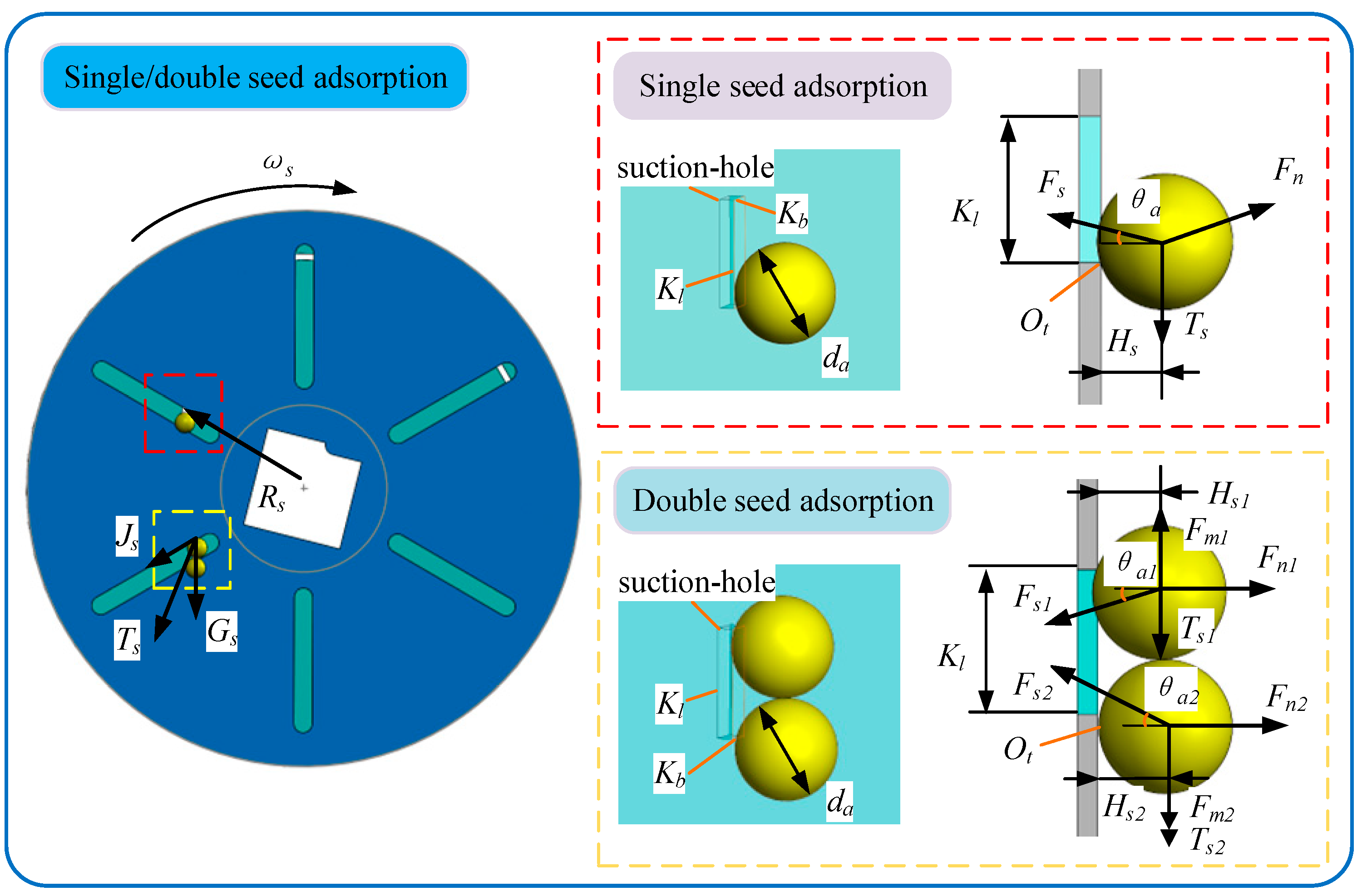
According to the velocity contour plots of the flow field, when the particle is at the suction hole center (U point), the airflow on both sides remains symmetrical, resulting in Fx and Fy being zero. As the particle moves along the x-/y-axes, the shape of the suction hole causes asymmetry in the front and rear flow fields, generating a force in the movement direction. However, the force component in the lateral direction remains zero due to the continued symmetry of the suction hole on both sides.
From the pressure distribution contour plots on the particle surface, it can be observed that the pressure gradient contour lines exhibit no distinct pattern, indicating a turbulent flow. Due to the influence of the suction hole boundary, the low-pressure region on the particle surface shifts along with the suction hole boundary. The conclusion that the suction hole shape affects the particle surface pressure distribution is consistent with the findings of previous research [
24].
4.3. Study on the Critical Adsorption Behavior of Dual-Particle Adsorption
(1) Dual-Particle Adsorption Experiment with Equal-Diameter Particles
A multiple regression analysis was performed on the test results presented in
Table 8, establishing a quadratic polynomial regression model with
Kl′ as the response variable and
Kb,
da, and
P as the test factors. After removing nonsignificant terms, the optimized regression equation is presented in Equation (13):
Analysis of variance (ANOVA) was conducted on the optimized model, as shown in
Table 10. The results show that the
p-value of the fitted model is significantly less than 0.01, while the lack-of-fit
p-value is greater than 0.05. The coefficient of determination
R2 is 0.949, indicating that the optimized regression model is highly significant and well-fitted and, thus, reliable. The effects of
da,
P, and
da2 on the critical suction hole length are highly significant (
p < 0.01), whereas the effects of
Kb,
Kb P, and
Kb2 on
Kl′ are significant (0.01 <
p < 0.05).
To investigate the interaction between
Kb and
P, response surface plots were generated using Design-Expert V8.0.6, as shown in
Figure 16.
When the particle diameter is at the central level (
da = 7 mm),
Kl′ decreases with increasing
P for a given
Kb. When
Kb = 1 mm, the reduction in
Kl′ with increasing
P is more pronounced. When
P < 7.5 kPa,
Kl′ decreases as
Kb increases. However, when
P > 7.5 kPa,
Kl′ first decreases and then increases with increasing
Kb, though the variation is relatively small. This indicates that the interaction between
P and
Kb significantly affects
Kl′, with
P having a greater impact. This conclusion is consistent with the influencing factors of pressure and velocity gradient explored by Wang Zhaoyang [
26].
(2) Dual-Particle Adsorption Experiment with Unequal-Diameter Particles
Figure 17 shows the critical suction hole length required for dual-particle adsorption when the particles have unequal diameters. The results indicate that the critical suction hole length is always smaller than the distance between the centers of the two particles.
In the adsorption measurement tests conducted using a dynamic–static combination plate test platform, two test particles were adsorbed sequentially onto the suction hole. The data indicate that when the upper particle diameter remains constant, decreasing the diameter of the lower particle reduces the critical suction hole length required for dual-particle adsorption.
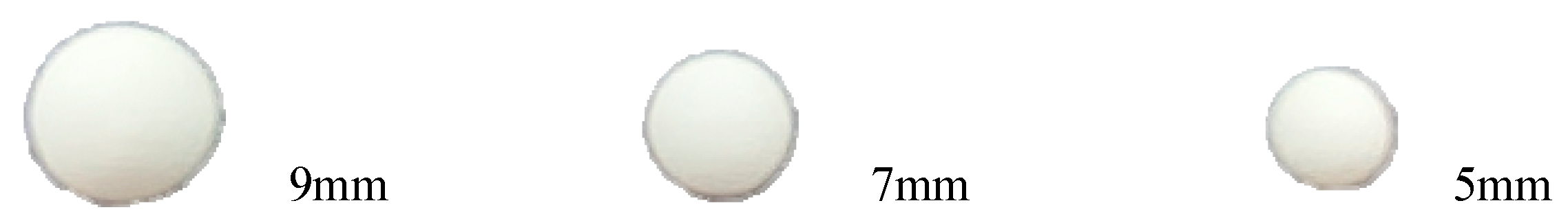
When the upper particle diameter is 9 mm, the suction hole length required to adsorb a lower particle of 9 mm is 1.23 times that required for a 7 mm particle and 1.35 times that for a 5 mm particle. Similarly, when the upper particle diameter is 7 mm, the suction hole length required to adsorb a lower 9 mm particle is 1.22 times that required for a 7 mm particle and 1.37 times that for a 5 mm particle. A similar trend is observed for an upper particle diameter of 5 mm.
When the lower particle diameter remains constant, decreasing the upper particle diameter also reduces the critical suction hole length. Additionally, when the lower particle diameter is larger than the upper particle diameter, the critical suction hole length required for multiple-seed adsorption increases. This is because larger particles, being heavier, are more prone to detachment from the suction hole.


 ,
, 


