Article

Study on the Design and Performance of a Seed Discharger for Peanut Plot Breeding Based on the CFD-DEM Method

1
Yellow River Delta Intelligent Agricultural Machinery Equipment Industry Research Institute, Qingdao 257300, China
2
College of Mechanical and Electrical Engineering, Qingdao Agricultural University, Qingdao 266109, China
3
College of Mechanical and Electronic Engineering, Xinjiang Agricultural University, Urumqi 830052, China
*
Authors to whom correspondence should be addressed.
Agriculture 2025, 15(3), 276; https://doi.org/10.3390/agriculture15030276
Submission received: 26 December 2024 / Revised: 22 January 2025 / Accepted: 23 January 2025 / Published: 27 January 2025
(This article belongs to the Section Agricultural Technology)

Abstract

:
In order to facilitate the peanut plot breeding process, a seed discharger for peanut plot breeding was designed and optimised. Two single stroke cylinders were used for seed replacement and to avoid confusion between different varieties of seeds. The working performance of the seed discharger was simulated by the CFD-DEM method. The simulation results showed that the seed suction hole could adsorb the seeds stably, the adsorption force at the seed suction hole was about 0.02 N, and the seed-clearing time was 0.31 s. When the rotation speed of the seed discharge cylinder was 25 r/min, the diameter of the seed suction hole was 6 mm and the working negative pressure was −5.5 kPa. The developed seed discharger was installed on the test bench to carry out the central composite design experiment, and the test results were analysed and optimised by Design-Expert software. The final parameters of the seed discharger were obtained as follows: rotational speed of the seed cylinder is 25 r/min, the diameter of the seed suction hole is 6 mm, and the working negative pressure is −6 kPa. This indicates that the design of the initial parameters is reasonable. Finally, the seed discharger was tested in the field. The results shown that the 95% confidence intervals for seeding pass rate, multiple-seed rate, and seed missing rate were (88.9557%, 93.1777%), (3.8137%, 6.4597%), and (2.1157%, 5.4777%), respectively, which met the requirements of peanut plot seeding.

1. Introduction

Peanut is an important oilseed crop in China [1,2,3], and the cultivation and promotion of excellent peanut varieties can increase peanut yields by at least 5% to 10%. The plot breeding trial is a process of selecting high quality varieties by sowing peanut seeds of different varieties into corresponding plots to compare growth traits [4,5,6]. The plot breeding trial is a necessary method for breeding new high-quality varieties [7,8,9] and is the most important part of the breeding process. During the process of plot trial, the quality of sowing is the key factor, which may affect the accuracy of the trial. Mechanised seeding can improve the accuracy of the plot trials, expand the scale of trials, shorten the cycle of breeding, and promote the breeding process of new peanut varieties [10].
The plot seed discharger is different from the seed discharger used in the field. The plot seed discharger needs to sow specific varieties of seeds in different plots and must avoid mixing seeds between different plots during the working process, so as to improve the operation efficiency as much as possible under the premise of guaranteeing the sowing quality. The seed dischargers used in the field work with only one variety of seed and are more focused on working efficiently. When the seed discharger is used in the field for plot sowing, it is necessary to stop and change the seed between different plots, and this process is usually difficult to completely clear out seeds from the seed discharger, which not only reduces work efficiency, but also leads to the confusion of different varieties of seeds, which makes the trial unscientific. The two main types of the seed discharger are mechanical and pneumatic. Pneumatic seed dischargers are more suitable for peanut seeds, which are easy to damage, due to less damage to the seed and adaptability to the seed size [11,12].
Many studies have been conducted on seed dischargers for plot breeding, but fewer seed dischargers are suitable for the peanut plot breeding [13]. They mainly solve the problem of seed mixing. For example, Ren Degang et al. [14] developed a seed discharger with a rotatable seed chamber, which is pulled by a one-way cylinder to clear the seed. Chang Xueliang et al. [15] developed a vertical disc-type air-suction peanut plot seed discharger by dividing the seed discharger into seed supply zone, seed discharge zone, and seed clearing zone, using two one-way cylinders to avoid the mixing of seeds between different plots. Hao Jianjun et al. [16] improved the spoon clamp seed discharger and developed a single-grain precision sowing unit for peanut plots. Liu Bing et al. [17] developed a roller-type plot seed discharger using the negative pressure to achieve the seed-clearing rate of 100%. However, the internal airflow mechanism of the plot seed discharger has not been analysed in detail.
The CFD-DEM method is often used in the design process of seed dischargers, where a discrete elemental model of the seed is created by EDEM software, and the optimisation of the seed discharger structure is achieved by coupling seeds with the air flow field [18,19]. For example, Yu Yaxin et al. [20] developed a combined directional seed discharger for pumpkin seeds based on the CFD-DEM method. Shang Zengqiang et al. [21] developed an air-suction soybean seed discharger based on the CFD-DEM method and optimised the parameters of the seed discharge disc. Wang Guowei et al. [22] developed a high-speed precision seed discharger for soybean with auxiliary seed filling air suction based on the DEM-CFD method. Ding Li et al. [23,24] developed a maize air-suction seed discharger and optimised the structure of the seed disc based on the CFD-DEM method.
In this paper, on the basis of the above research, a seed discharger for peanut plot breeding was developed, in which the interior of the seed discharger is divided by two cylinders. The supply and clearing of seeds in the seed chamber are realised by controlling the working status of seed-supplying and seed-clearing cylinders to avoid the mixing of different varieties. The initial parameter range is formulated based on the Chinese agricultural machinery design standard, the structural parameters are examined and optimised by fluent software and the CFD-DEM method, and the final parameters are determined by bench test. Confidence intervals for seed pass rate, reseeding rate, and leakage rate of the seed discharger were finally obtained after field trials.

2. Materials and Methods

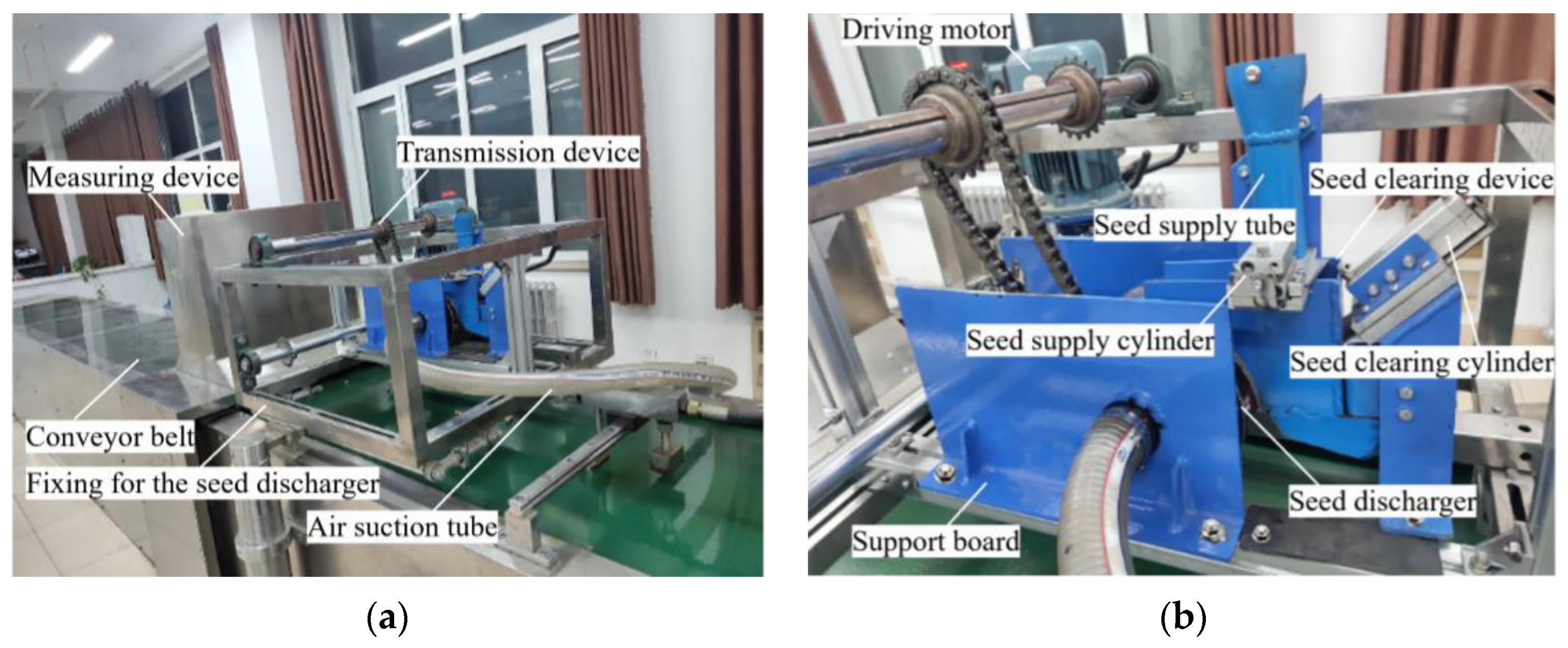
2.1. Composition and Working Principle of the Seed Discharger

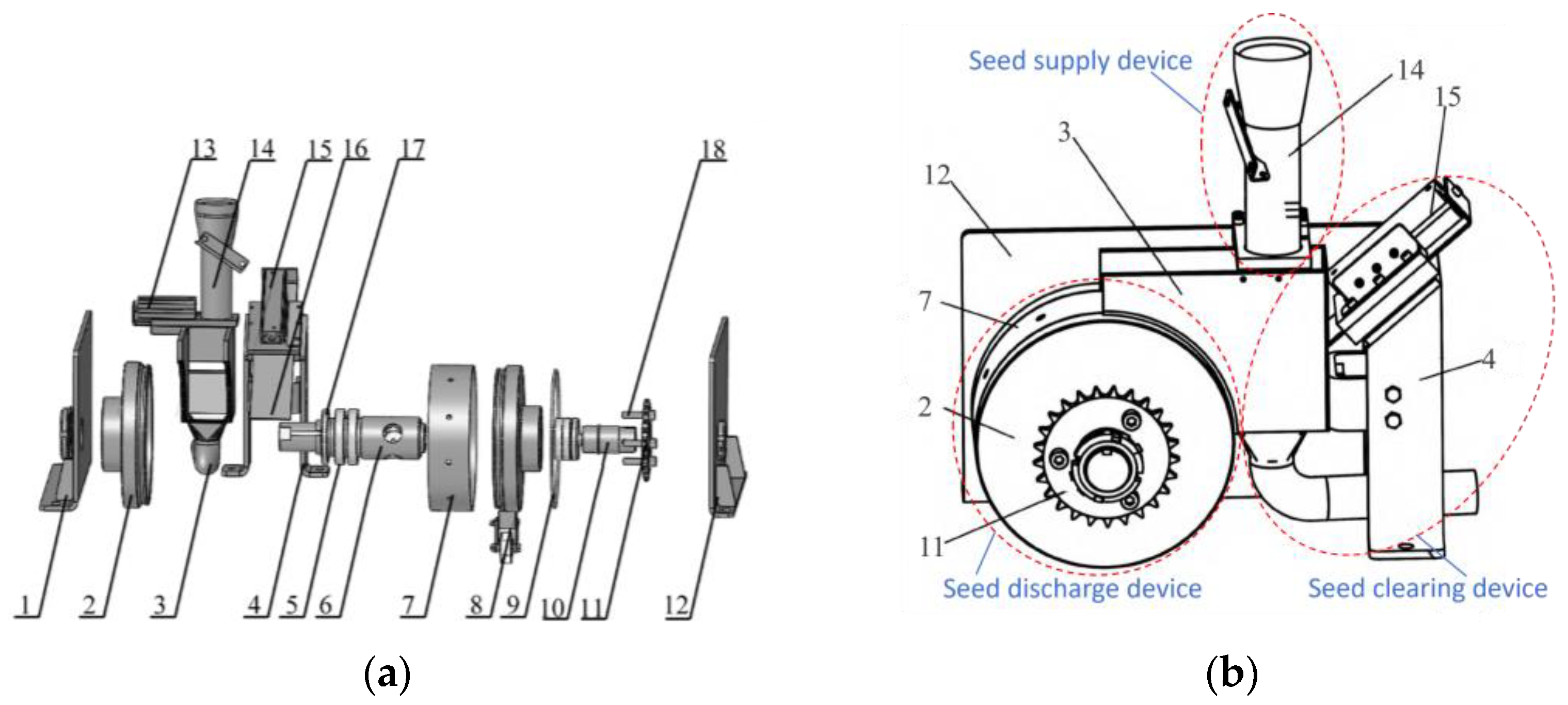
2.1.1. Composition of the Seed Discharger

The peanut plot seed discharger consists of seed discharge device, seed supply device, seed-clearing device and support device, as shown in Figure 1. The seed supply device consists of seed supply tube, seed supply plate, and seed supply cylinder (40 mm stroke). The seed discharge device consists of two covers, seed discharge cylinder, air suction tube, plug hole wheel, and a chain wheel. The chain wheel is connected to the drive of the planter and drives the seed discharge disc to rotate. The seed-clearing device consists of a seed-clearing board, a seed-clearing cylinder (70 mm stroke), and a seed-clearing tube. The seed supply device is located above the seed discharge device for providing seeds. The seed-clearing device is fixed under the support plate and connected to the seed chamber of the seed discharge device for clearing the seeds in the seed chamber. The two sides of the seed discharge device are fixed by the support plate and mounted on the planter.

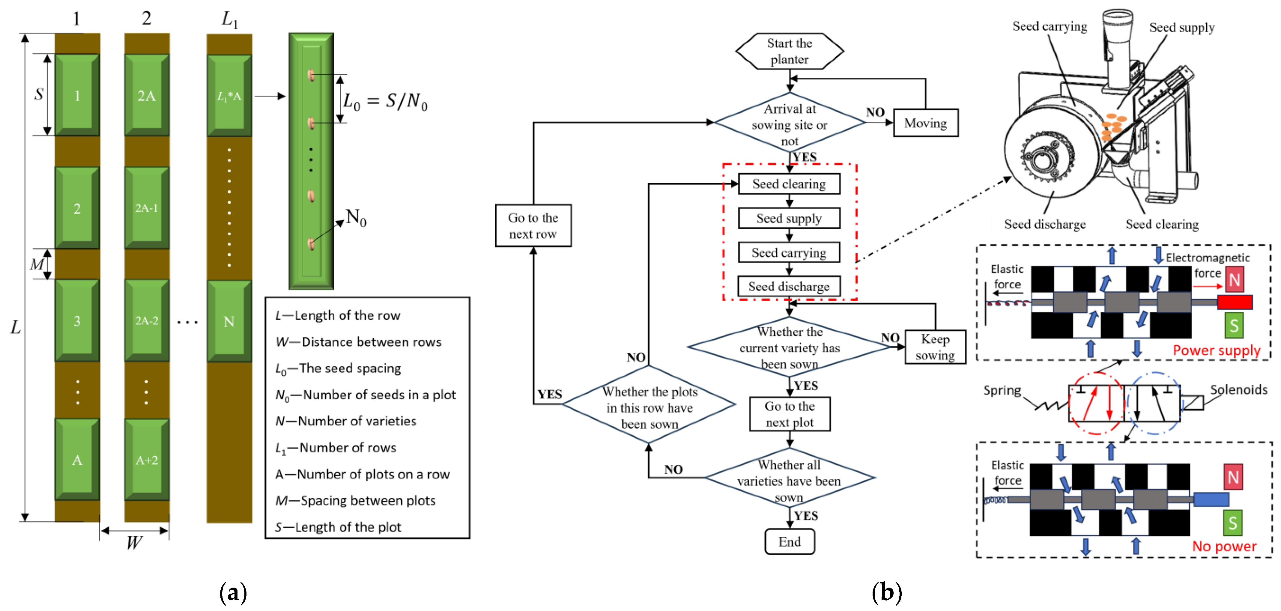
2.1.2. Working Principle of the Seed Discharger

The seed discharger is mounted inside the planter and discharge seeds as the planter advances. The drive gear of the seed discharger is connected to the ground wheel drive system of the planter and rotates as the planter moves forward. As shown in Figure 2a, seeds in the chamber need to be exchanged before moving in the next plot. When the planter has finished planting one row, it needs to go to the next row to plant the next plot.
When the planter has finished sowing a plot, the seed-clearing plate is pulled by the seed-clearing cylinder, and the remaining seeds in the seed chamber falls into the seed-clearing tube, under the negative air pressure. After the seed-clearing process has finished, the solenoid valve controls the cylinder to switch the position of the seed supply plate under the action of pneumatic force, and the seeds fall from the seed supply plate into the seed chamber of the seed discharger to realise the supply of seeds.
While the planter is working, the working states of the seed discharger consists of four kinds, namely seed supply, seed carrying, seed discharge, and seed clearing. The seed supply device and seed-clearing device are the key components that avoid the mixing of seeds between the different plots. The seed supply cylinder is a two-position three-way cylinder with a stroke of 40 mm, the seed-clearing cylinder is a three-position two-way cylinder with a stroke of 70 mm, and the seed supply and seed-clearing cylinders are controlled by solenoid valves.
One end of the air suction tube is connected to an air suction fan through a plastic tube. When the suction fan operates, the air inside the seed discharge cylinder is drawn out, creating negative pressure. The air inside the seed chamber is pulled from the seed suction hole into the seed discharge cylinder. Seeds in the seed chamber are adsorbed at the seed suction hole under negative pressure. When the seed enters the seed discharge zone, the suction force at the suction hole disappears due to the nelon wheel blocking the suction hole, and the peanut seed falls under the action of gravity.

2.2. Material Parameters of Peanut Seeds and Seed Discharger Materials

The sizes of peanut seeds are important for the design of the seed discharger. In this paper, Luhua 11 peanut was selected. Three groups of peanut seeds were selected with 150 seeds each, and seed length L, seed width W, and seed thickness H were measured using vernier callipers with an accuracy of 0.01 mm, as shown in Figure 3a. Measurements of the modulus of elasticity, Poisson’s ratio, and coefficient of static friction of peanut seeds were conducted by experimental apparatus, as shown in Figure 3.
The material of the seed discharger was selected as stainless steel. The material parameters of peanut seeds, stainless steel, and the contact parameters between seeds and between seed and seed discharger were measured, as shown in Table 1.

2.3. Design of Seed Supply and Clearing Devices

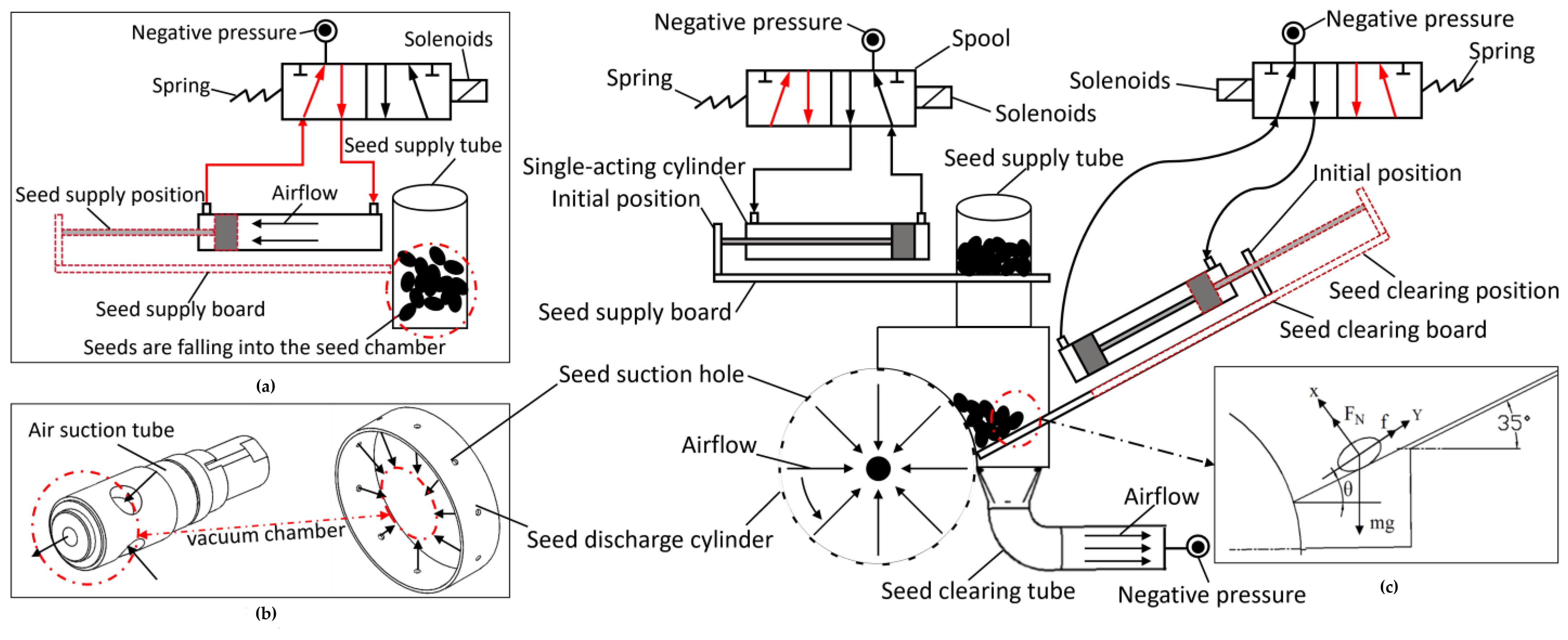
2.3.1. Principle of Operation of the Seed Supply and Clearing Device

The seed supply device and seed-clearing device are, respectively, designed to achieve the seed supply and seed-clearing processes, and neither device interferes with each other, as shown in Figure 4. The seed supply cylinder and seed-cleaning cylinder are the driving devices for the seed supply plate and seed-clearing plate. The solenoid valve receives an electrical signal and generates a magnetic force that attracts the spool to move and change the path of the air, as shown in Figure 4a. When the solenoid valve receives the electrical signal again, the magnetic force is lost and the spool returns to its original position under the action of the spring by changing the air pressure difference between the two sides of the cylinder to achieve the two movements of extending and retracting. The seed supply cylinder drags the seed supply plate to move under the action of the solenoid valve to realise the opening and closing of the seed supply tube. The seed-clearing cylinder drags the seed-clearing plate to realise the clearing of seeds in the seed chamber under the action of the solenoid valve.
The seed chamber of peanut seeds is an important part to ensure seed supply and improve the efficiency of seed adsorption. When the tilt angle of the seed-clearing plate is 35°, the falling speed of the seed is slow, which can improve the possibility of the seed being adsorbed, and also ensure that the seed enters the seed-clearing pipe smoothly. The 70 mm stroke cylinder can ensure seeds enter the seed-clearing tube instantly and achieve 100% seed-clearing rate. The seed-clearing cylinder of the seed-clearing device is connected to the air suction tube, and the seed-clearing tube with an inner diameter of 29 mm is selected according to the size of peanut seeds and the material of the tube, as shown in Figure 4b. When the seed discharger clears the seed, the cylinder controls the seed-clearing plate to unload the seed into the seed-clearing box. And then, the seeds will fall into the seed-clearing box by the negative pressure.
The force of the seed in the seed-clearing process was analysed as shown in Figure 4c. The peanut seeds in the seed chamber slide along the seed-clearing plate to the seed discharge cylinder under the action of the support force, gravity, and friction.
Σ F X = F N m g cos θ = 0 Σ F Y = m g sin θ f = 0 ,
where FN is the support force of the clearing plate on the seed, in N; f is the friction force of the clearing plate on the seed, in N; θ is the inclination angle of the clearing plate, in °; m is the mass of the seed, in kg; and g is the acceleration of gravity, in N/kg.

2.3.2. Theoretical Analysis of the Seed Absorption Process

As shown in Figure 5, in the seed discharge stage, the seed firstly moves to the suction hole under the action of the airflow field, and then the seed will be stably adsorbed on the suction hole and follow the seed suction hole in a circular motion. For the peanut seeds on the clear plate to be successfully adsorbed onto the suction holes, the adsorption force on the seed at the suction hole needs to overcome the resistance generated by the seed population as well as the force of gravity. After the seed is adsorbed on the seed suction hole, the centrifugal force generated by the movement of the seed needs to be overcome additionally as the seed discharge cylinder moves in a circular motion.
When the peanut seeds are not in contact with the seed discharge cylinder, they are subjected to the action of adsorption force, causing them to move towards the seed suction hole with acceleration; the state of seed movement at this moment is shown in Equation (2).
F Y = F + F N cos θ + f sin θ + G sin α = m a F X = F N sin θ + G cos α f cos θ = 0 f = tan γ F N ,
where F N is the force of the seed by other seeds, in N; F is the suction force on the seed produced by the negative pressure, in N; FN is the support force on the seed by the seed discharger cylinder, in N; G is the gravitational force of the peanut seed, in N; f is the friction force on the seed by the discharger cylinder; f is the friction force on the seed by other seeds; a is the acceleration of the seed produced by the combined force, in m/s2; θ is the angle between the force of other seeds on the seed and the radius of rotation, in °; μ is the angle of static friction between the seed and the seed discharger cylinder, in (°); γ is the angle of static friction between the seeds, in (°); and α is the angle between the line of the seed and the rotating centre of the seed discharger and the horizontal plane, in (°).
The suction force of the seed suction hole is obtained from Equation (2), as shown in Equation (3).
F = m a G cos α + θ + tan γ sin α + θ tan γ cos θ sin θ .
According to Newton’s second law, a peanut seed will achieve acceleration when the adsorption force is sufficient to overcome other resistance. When the peanut seed moves up to the seed suction hole, it will be subjected to the support force and friction force of the seed discharge cylinder and will follow the seed discharge cylinder to do a stable circular motion under the action of the suction force. The state of the seed’s motion at this moment is shown by Equation (4).
F Y = F + F N cos θ + f sin θ + G sin α F N = m a F X = F N sin θ + G cos α + f f cos θ = 0 f = tan μ F N f = tan γ F N ,
where μ is the static friction coefficient between the seed and the seed discharge cylinder; ω is the angular velocity of the seed discharge cylinder, in rad/s; and R is the radius of the seed discharge cylinder, in m.
The suction force of the seed suction hole can be obtained from Equation (4), as shown in Equation (5).
F = m ω 2 R F N cos θ tan μ + sin θ tan γ tan μ tan γ cos θ + sin θ tan μ G sin α tan μ + cos α tan μ .
Negative pressure at the seed suction hole needs to be determined according to the adsorption force of the peanut seed in the seed carrying process, and the adsorption force of the peanut is shown in Equation (6). As shown in Equation (6), the larger the diameter of the seed suction hole, the larger the contact area between the peanut seed and the seed-sucking hole, and the larger the adsorption force that the peanut seed is subjected to. The ideal plan is to make the contact surface between the seed and the suction hole as large as possible to reduce the magnitude of the negative pressure required and reduce power consumption.
F = C d A ρ v 0 2 2 = C d Δ P N π d 2 2 ,
where Cd is the coefficient of damping force; ρ is the density of air, in kg/m3; d is the diameter of the seed suction hole, in m; v0 is the average speed of the airflow acting on the seed at the seed suction hole, in m/s; A is the projected area of the seed in the direction of vertical movement, in m2; and ΔPN is the difference in internal and external pressures of the seed at the seed suction hole, in Pa.

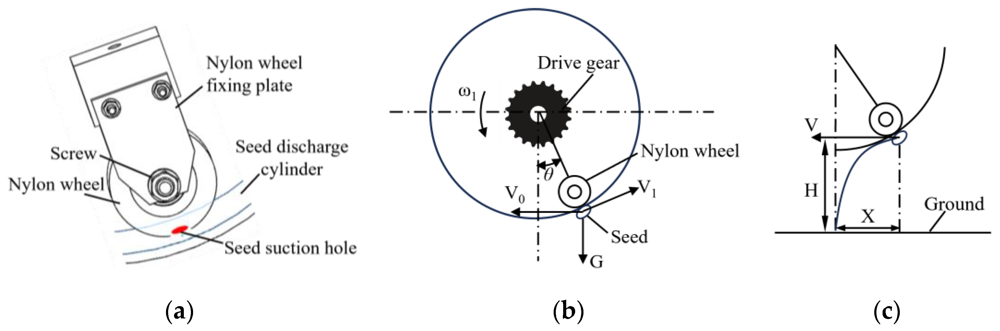
2.4. Design and Theoretical Analysis of Seed Discharge Device

Structural Design of the Seed Discharge Cylinder

The rotational speed of the seed discharge cylinder is an important factor in the sowing process. Increasing the rotational speed of the cylinder can increase the working efficiency of the planter. However, as the rotational speed of the cylinder increases, the linear velocity of the seed suction holes increases and the seed may be not adsorbed at the suction hole in time, which results in the seed missing. According to the requirements of the “Agricultural Machinery Design Manual”, the maximum linear velocity of the suction hole is not greater than 0.35 m/s, and the diameter of the seed discharge cylinder ranges from 140 to 260 mm. Considering the physical properties of the peanut seed, the structure of the seed discharger, the power consumption of the air fan, and other factors, the final choice of the seed discharge cylinder diameter of 190 mm. At this time, the limit of the seed discharger rotational speed is 35 r/min. The relationship between the rotational speed and linear velocity at the seed suction hole is shown in Equation (7).
ν = n π 30 R ,
where v is the linear velocity at the seed suction hole, in m/s; R is the radius of the seed discharge cylinder, in mm; and n is the rotational speed of the seed discharge cylinder, in r/min.
The structure of the seed-suction hole directly affects its ability to adsorb seeds. The current seed suction holes have straight holes, conical holes, and sunken holes, among which straight holes have the largest airflow velocity and the best adsorption effect on seeds. According to the “Agricultural Machinery Design Manual” and the size of the seeds in Table 1, the diameter of the seed suction holes can be calculated according to Equation (8) in the range of 5.03–7.85 mm.
0.64 b d 0.66 b b = W + H + L 3 ,
where d is the diameter of the seed suction hole, in mm; and b is the average width of the seed, in mm.
The vacuum of the seed suction hole and the rotational speed of the seed discharge cylinder are the main factors affecting the working performance. According to the “Agricultural Machinery Design Manual”, the maximum value of the vacuum required by the seed suction hole can be calculated by Equation (9).
H c max = 80 K 1 K 2 m g C π d 3 1 + v 2 g r + λ ,
where Hcmax is the air-suction vacuum’s minimum, in kPa; C is the centre of gravity of the seed from the distance between the row of seed discs, in cm; m is the mass of a seed, kg; v is the row of seed disc suction hole in the centre of the linear speed, in m/s; r is the row of seed disc suction hole at the radius of rotation, in m; g is the acceleration of gravity, in m/s2; λ is the seed of friction resistance composite coefficient, in λ = (6~10) tanα, α is the natural angle of repose of the seed, in degrees; K1 is the reliability coefficient of seed suction, ranging from 1.8 to 2.0, and it takes a smaller value when the seed mass of thousands of grains is small and the seed shape is near-spherical; K2 is the coefficient of the external conditions, ranging from 1.8 to 2.0, and it takes a larger value when the seed mass of thousands of grains is large; and d is the diameter of the hole of the seed suction, in cm.
According to Equation (9), the maximum vacuum at the seed suction holes can be taken in the range of (−5.88, −7.85) kPa.
The planter sows the seed at a certain speed of advance and the distance between seeds are determined with the increase in the number of seed suction holes on the seed discharge cylinder, the rotational speed of the seed discharge cylinder is reduced, as well as the linear speed. The seeds will be adsorbed longer and better. However, when the number of seed suction holes increases to a certain extent, the distance between the seed suction holes decreases, and the seed suction holes will interfere with each other, affecting the stability of seed adsorption. The number of seed suction holes of the seed discharger can be calculated according to Equation (10).
Δ l 1 2 l max Z = π D d + Δ l ,
where Δl1 is the arc length between the centre of adjacent seed suction holes on the seed discharge cylinder, in mm; lmax is the maximum size of the seed, in mm; Z is the number of seed suction holes; D is the diameter of the seed discharge cylinder, in mm; d is the diameter of the seed suction holes, in mm; and Δl is the shortest distance between the adjacent seed suction holes, in mm.
The number of seed suction holes of the seed discharge cylinder is calculated to be 10 and evenly distributed on the circumference of the middle of the seed discharge cylinder.

2.5. Design of the Seed Discharge Device

The surface of the nylon wheel is in contact with the inner wall of the seed discharge cylinder. When the seed discharge cylinder rotates, the nylon wheel rotates by friction. When the seed suction hole is plugged by the nylon wheel, the airflow from the seed suction hole is cut off and the absorption force is removed. Then, the seeds are disengaged from the seed suction hole by gravity. As shown in Figure 6a, a wheel made of nylon material is designed to be installed inside the air suction shaft to plug the seed suction holes. The airflow is cut off by plugging the seed suction hole through the surface of the nylon wheel, as shown in Figure 6b. The outer diameter of the wheel is 40 mm and the thickness of the wheel is 12 mm, which provides air pressure isolation for seed discharge. As shown in Figure 6c, the seed loses the adsorption force, and then it makes uniform linear motion in the horizontal direction and free-fall motion in the direction of gravity. H is the height of the seed from the ground when it is discharged.
In order to keep the peanut seeds as immobile as possible in the horizontal direction, the mounting angle of the nylon wheel needs to be designed as shown in Figure 6c. Neglecting the effect of the air resistance, the equation of motion of the seed as it falls is shown in Equation (11).
V 1 = ω R V = V 1 cos θ V 0 ω = 2 π n 60 t = 2 H g ,
where V is the horizontal velocity of the seed, in m/s; V1 is the linear velocity of the seed suction hole, in m/s; V0 is the working speed of the planter, in m/s; R is the radius of the seed discharge cylinder, in mm; n is the rotational velocity of the seed discharge cylinder, in ir/min; ω is the angular velocity of the seed discharge cylinder, in rad/s.
θ = arccos 30 V 1 π n R X = V 0 cos θ π n 30 R 2 H g .
According to Equation (12), it can be seen that the rotational velocity of the seed discharger affects the movement of the seed in the seed falling stage. By analysing the seed falling stage, it was found that when the angle θ = 27° between the nylon wheel and the vertical direction, the peanut seeds could move at near zero speed in the horizontal direction. The actual seed drop distance X of peanut seeds can be determined by further calculation.

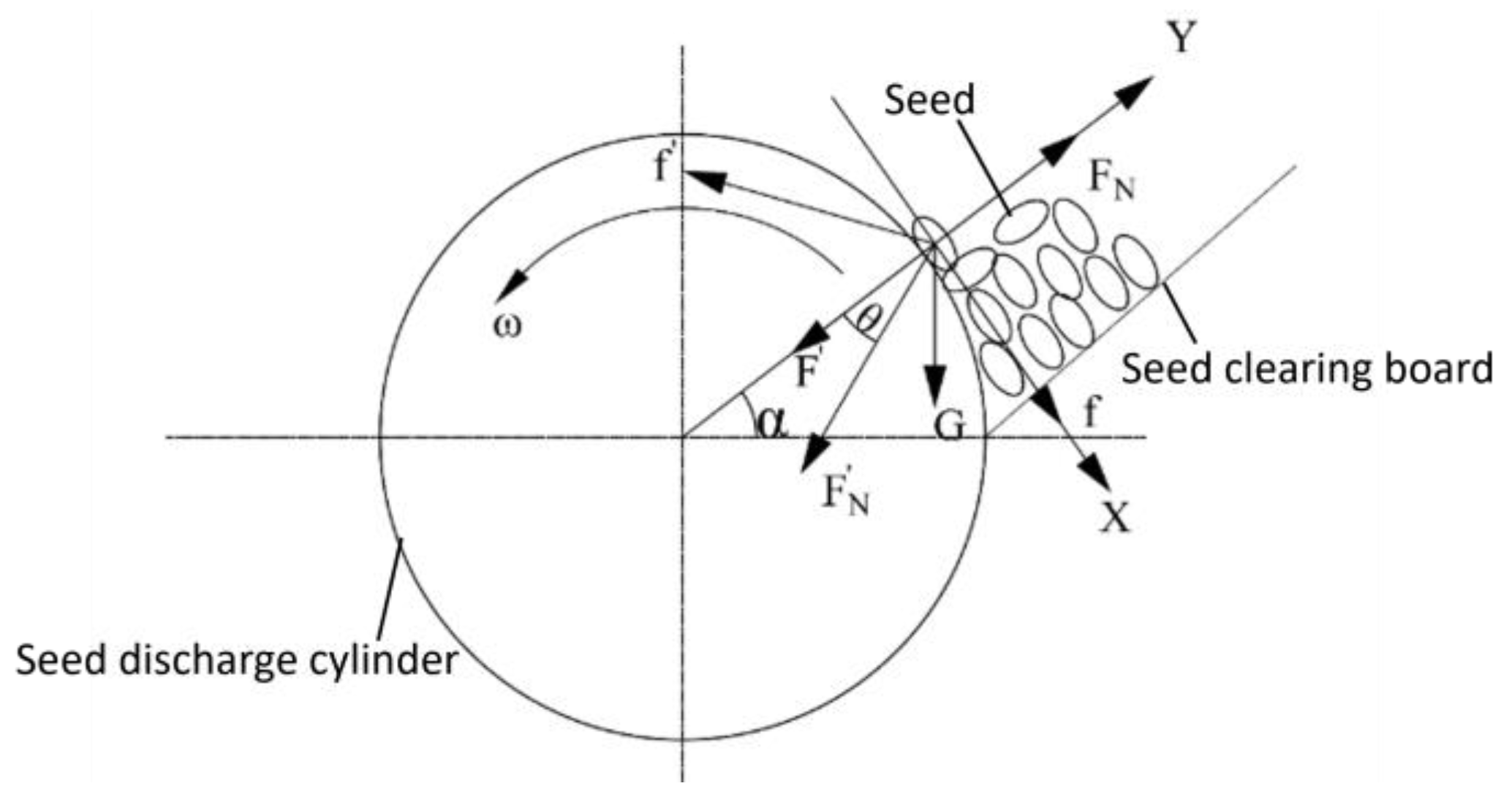
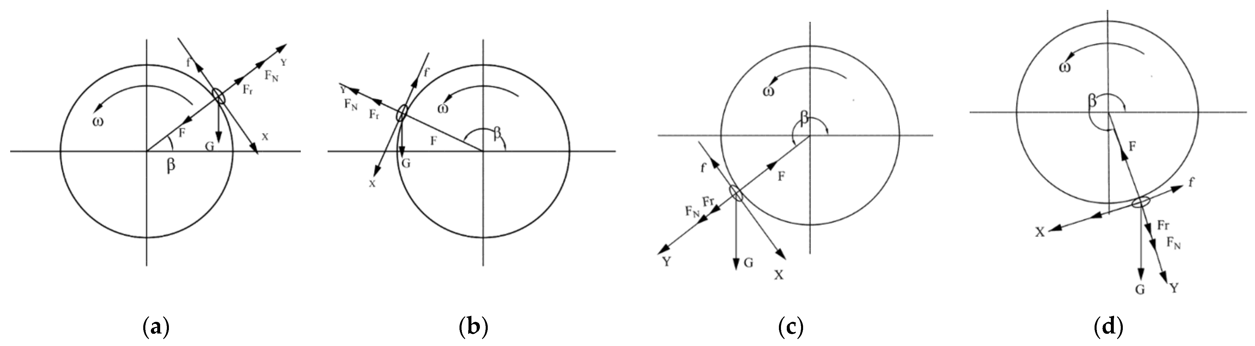
Analysis of the Seed Carrying Process

After being attached to the seed suction hole, the peanut moves in a circular motion with the seed suction hole. At different positions, the expression of its force is different. The minimum suction force required to keep the seed stably adsorbed on the seed is also different. So, it is necessary to analyse the expression of the suction force required at different positions. At this stage, the peanut seed moves in a circular motion under the action of its gravity G, the adsorption force F generated by the seed suction hole, the normal support force FN, and the tangential friction ƒ generated by the seed discharger on the peanut seed, and will generate the centrifugal force Fr. We set the angle between the peanut seed and the seed discharger in the horizontal direction as β and established the mechanical models in the normal and tangential directions according to the range of the variation in the angle, respectively, as shown in Figure 7.
(1) When 0° < β < 90°, the forces on the peanut seed in the normal and tangential directions are shown in Figure 7a, and the balance equations are established in the normal and tangential directions, respectively, as shown in Equation (13).
Σ F X = 0 ,   G cos β f = 0 Σ F Y = 0 ,   F N + F r G sin β F = 0 f = tan μ F N F r = m ω 2 R .
According to Equations (5), (6), and (13), the adsorption force to be provided at the seed suction hole was calculated as shown in Equation (14).
F = C d Δ P N π d 2 2 m ω 2 R + G cos β tan μ sin β = m ω 2 R + cos β + μ sin μ .
When 0° < β < 90°, the minimum adsorption of the peanut seed decreases with increasing β. The extreme value of adsorption force in this range is shown in Equation (15).
β = 0 ° ,   F max = m ω 2 R + G tan μ β = 90 ° ,   F min = m ω 2 R G .
(2) When 90° < β < 180°, the forces on the peanut seed in the normal and tangential directions are shown in Figure 7b, and the balance equations are established in the normal and tangential directions, respectively, as shown in Equation (16).
Σ F X = 0 ,   f G cos 180 ° β = 0 Σ F Y = 0 ,   F N + F r G sin 180 ° β F = 0 f = tan μ F N F r = m ω 2 R .
According to Equations (5), (6), and (16), the adsorption force to be provided at the seed suction hole was calculated as shown in Equation (17).
F = C d Δ P N π d 2 2 m ω 2 R G cos β μ sin μ .
When 90° < β < 180°, the minimum adsorption of the peanut seed increases with increasing β. The extreme value of adsorption force in this range is shown in Equation (18).
β = 90 ° ,   F min = m ω 2 R G β = 180 ° ,   F max = m ω 2 R + G tan μ .
(3) When 180° < β < 270°, the forces on the peanut seed in the normal and tangential directions are shown in Figure 7c, and the balance equations are established in the normal and tangential directions, respectively, as shown in Equation (19).
Σ F X = 0 ,   G cos β 180 ° f = 0 Σ F Y = 0 ,   F F N F r G sin β 180 ° = 0 f = tan μ F N F r = m ω 2 R .
According to Equations (5), (6), and (19), the adsorption force to be provided at the seed suction hole was calculated as shown in Equation (20).
F = C d Δ P N π d 2 2 m ω 2 R G cos β μ sin μ .
When 180° < β < 270°, the minimum adsorption of the peanut seed decreases with increasing β. The extreme value of adsorption force in this range is shown in Equation (21).
β = 180 ° + μ ,   F max = m ω 2 R + G sin μ β = 270 ° ,   F min = m ω 2 R G cos 270 ° μ sin μ .
(4) When 270° < β < 297°, the forces on the peanut seed in the normal and tangential directions are shown in Figure 7d, and the balance equations are established in the normal and tangential directions, respectively, as shown in Equation (22).
Σ F X = 0 ,   G cos β 270 ° f = 0 Σ F Y = 0 ,   F F N F r G sin β 270 ° = 0 f = tan μ F N F r = m ω 2 R .
According to Equations (5), (6), and (22), the adsorption force to be provided at the seed suction hole was calculated as shown in Equation (23).
F = C d Δ P N π d 2 2 m ω 2 R G cos β μ sin μ .
When 270° < β < 297°, the minimum adsorption of the peanut seed decreases with increasing β. The extreme value of adsorption force in this range is shown in Equation (24).
β = 297 ° ,   F max = m ω 2 R G sin μ β = 270 ° ,   F min = m ω 2 R G cos 297 ° μ sin μ .
According to the mechanical analysis of the seed in the different seed-carrying processes above, the adsorption force on the peanut seed decreases with the increase in β, after which it increases before it decreases again. The peanut seed is least likely to adsorb the seed when the value of β is 180° + μ. The size of the negative pressure in the seed chamber can be selected based on the result.

2.6. Determination of Key Structural Parameters Based on Fluent

2.6.1. Simulation Model Building and Parameter Setting

The air chamber inside the seed suction holes and the suction shaft were modelled using SOLIDWORKS 2023 software, respectively, and the model was exported to ICEM-CFD for meshing. As shown in Figure 8, we defined the seed suction holes and the suction shaft as fluid domains. We selected the contact surface between the seed suction holes and the suction shaft as the interface. The outer surface of the seed suction hole was set as the pressure inlet, while one end of the air suction tube was set as the pressure outlet.

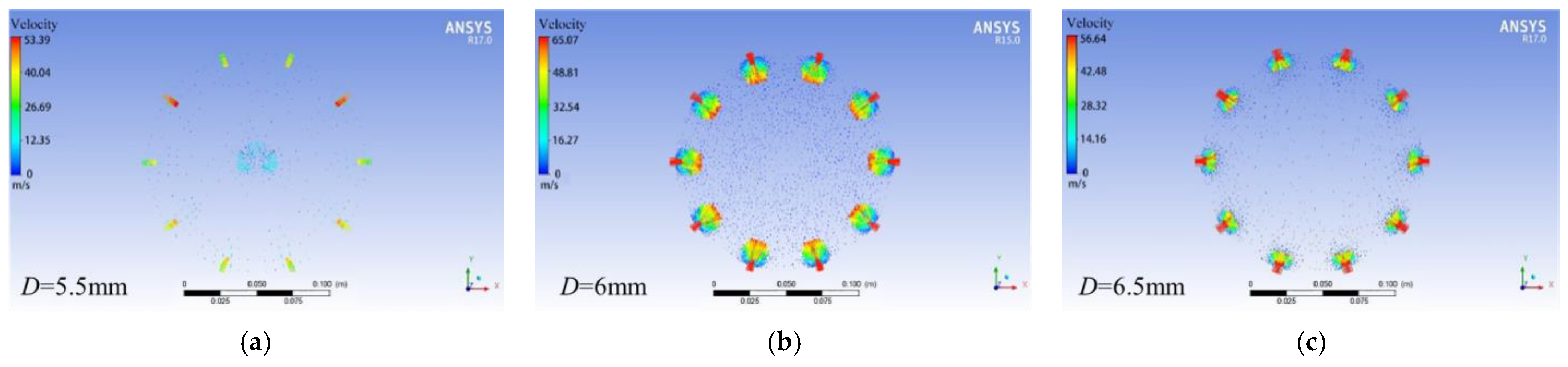
2.6.2. Simulation of Fluid Field with Different Seed Suction Hole Diameters

According to the research described in Section 2.5, three types of seed suction holes, with diameters of 5.5, 6, and 6.5 mm, were selected. The outlet pressure was set to −5.5 kPa, and the rotational speed of the seed discharge cylinder was 25 r/min. As shown in Figure 9, when the diameter of the seed suction hole is 6 mm, the airflow velocity around the seed suction hole is higher than that of the other sizes of seed suction holes, indicating that the 6 mm diameter seed suction hole is more effective at adsorbing the seed.
The seed discharger with a diameter of 6 mm in the seed suction hole was sliced in cross-section, as shown in Figure 10. The airflow velocity changed in the inlet and outlet ends of the seed suction hole and diffused in the tail of the flow velocity at the end connected with the air chamber. Pressure changes were mainly concentrated at the seed suction hole, and the air pressure inside the air chamber was relatively stable. The stable air pressure provided at the seed suction hole ensures that a stable adsorption force is generated during seed adsorption, which is easier for seed adsorption.

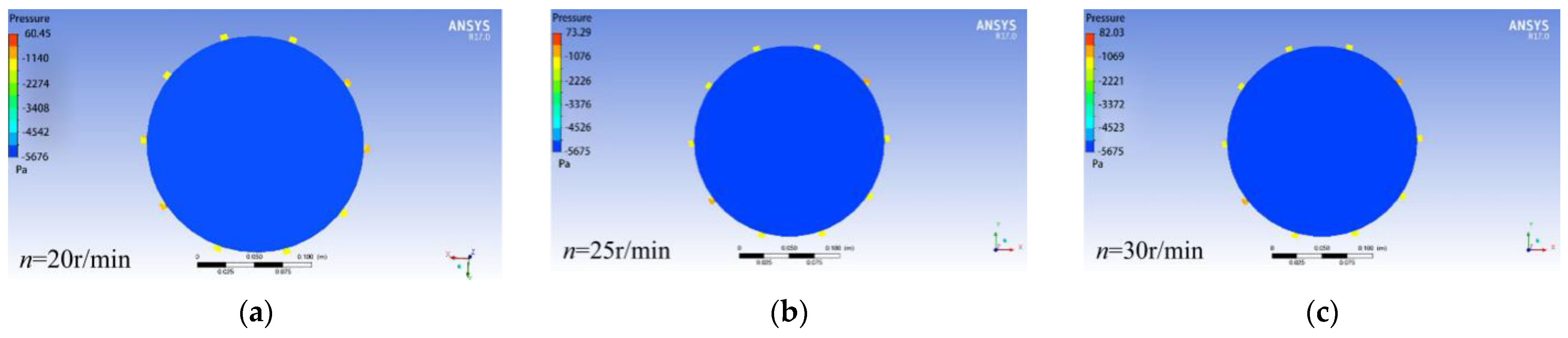
2.6.3. Simulation of Flow Field at Different Rotational Speeds of the Seed Discharge Cylinder

According to the previous analysis, the rotational speed of the seed discharge cylinder is one of the important parameters affecting the sowing quality. In order to observe the field of fluid inside the seed discharger with different rotational speeds, three kinds of rotational speeds of the seed discharger, 20, 25, and 30 r/min, were selected for analysis. The negative air pressure of −5.5 kPa was set, and the diameter of the seed suction hole was 6 mm, as shown in Figure 11. The pressure maps of the cross-section of the airflow field at different rotational speeds are basically the same, and the internal air chamber pressure is smooth.
As shown in Figure 12, the pressure and velocity of the fluid in different sections of the seed discharger are monitored in the CFD-POST 2022.2 software. As a result, the seed discharger’s rotational speed has almost no effect on the internal air chamber pressure. Therefore, rotational speed of 25 r/min was selected.

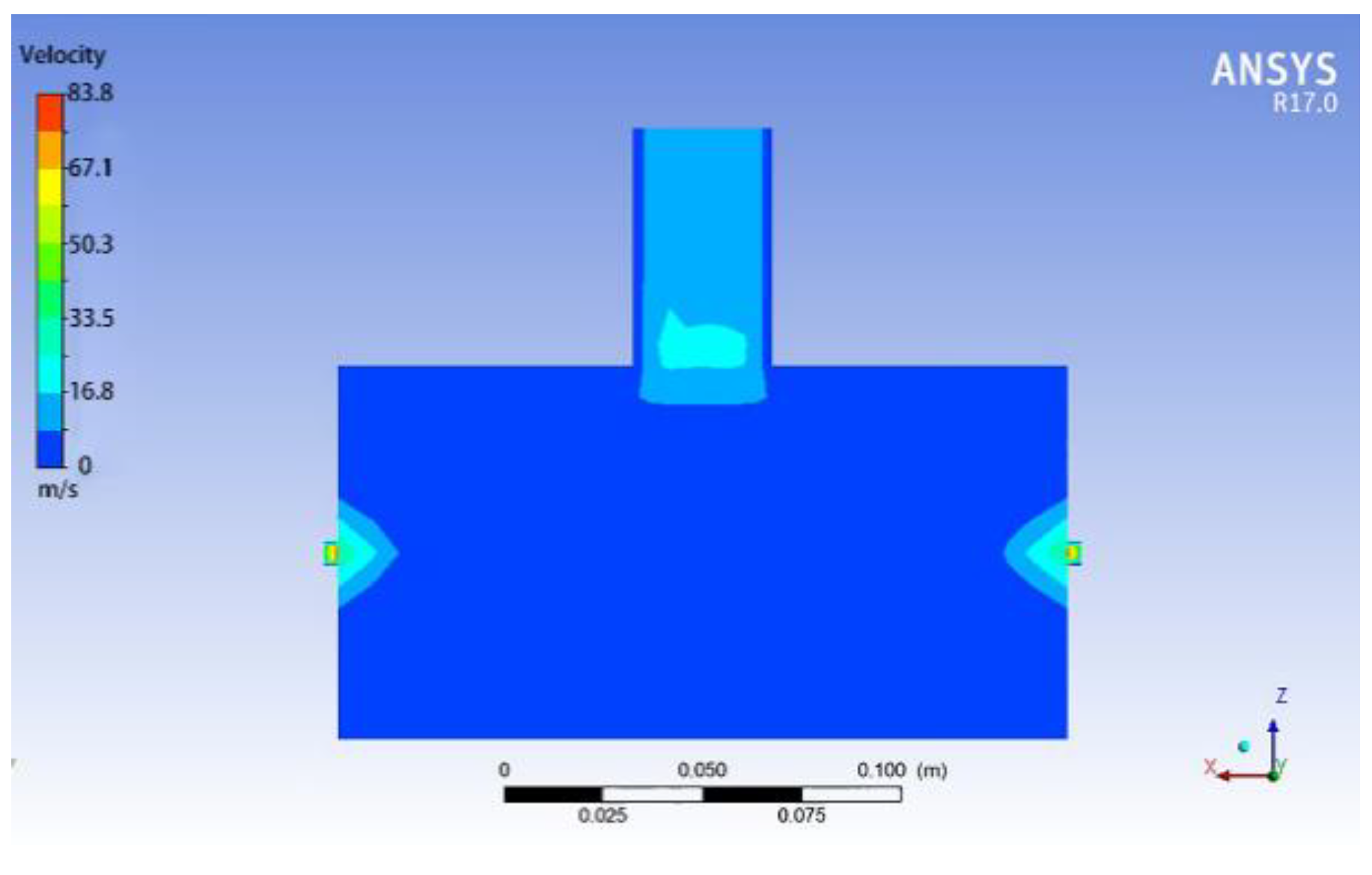
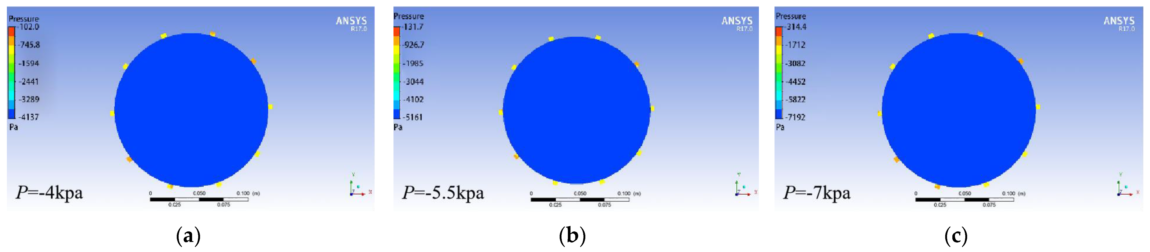
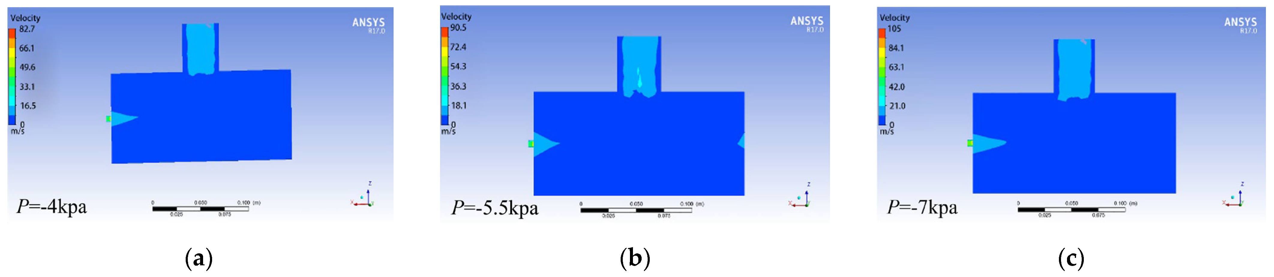
2.6.4. Simulation of the Flow Field with Different Negative Pressures

In order to observe the flow field within the seed discharger at various negative pressures, negative pressure values of −4, −5.5, and −7 kPa were selected for analysis. The rotational speed of the seed discharge cylinder was set to 25 r/min, and the diameter of the seed suction hole was 6 mm, as shown in Figure 13. The cross-section and longitudinal section of the airflow field were sliced in CFD-POST. From the cross-section slices, it can be observed that pressure variations occur near the seed suction hole of the seed discharger, while the pressure inside the air chamber remains essentially unchanged.
As known from Figure 14, from the longitudinal section slices, it can be observed that the negative air pressure at the pressure outlet appeared to decay, while the pressure inside the air chamber did not change significantly. The pressure between the seed suction holes did not interfere with each other. Negative pressure is generated by the fan. The higher the required pressure, the more power the fan operates and the more energy is required to operate the seed discharger. After comprehensive consideration, the pressure outlet was set to −5.5 kPa.

2.7. Coupling Simulation Based on CFD-DEM Method

2.7.1. Parameter Setting of the Simulation Model

We set the rotational speed of the seed discharge cylinder in EDEM to be 25 r/min, and the same rotational speed in the corresponding flow field region in FLUENT. The time step of EDEM was set to 1 × 10⁻⁷ s, the time step of FLUENT was set to 1 × 10⁻⁵ s, and the number of simulation steps was set to 105, i.e., the simulation time was 1 s. The inlet pressure was set to 0 kPa and the outlet pressure was set to −5.5 kPa in FLUENT. The maximum number of iterations in each time step of FLUENT was set to 50. The coupled drag force model was set to Ergun and Wen&Yu.
The API (secondary development programme for particle fields) was used to replace the particles and obtain a discrete model of the peanut seed. Since the minimum grid cell volume of the airflow field was 7.03 × 10⁻¹⁰ m3, small particles with a radius of 0.55 mm were selected. The volume of the particles was 6.96 × 10⁻¹⁰ m3, and the total volume of the peanut seed was 9 × 10⁻⁷ m3. The number of particles to be filled was calculated according to Equation (25). The filling volume coefficient α was chosen to be 0.6 and the number of filled particles was calculated to be 736.
α V T = N V S ,
where α is the filling volume coefficient; N is the number of filling particles; VT is the volume of the seed, in m3; and VS is the volume of the filling particles, in m3.
We imported the simplified model of the seed discharge cylinder into EDEM and created a particle factory. We set the number of seeds to be 25 and began particle replacement from 0.13 s. The replacement particles were output by EDEM Simulation Deck and coupled from 0 s. Fifteen seeds were selected as detect points, as shown in Figure 15.

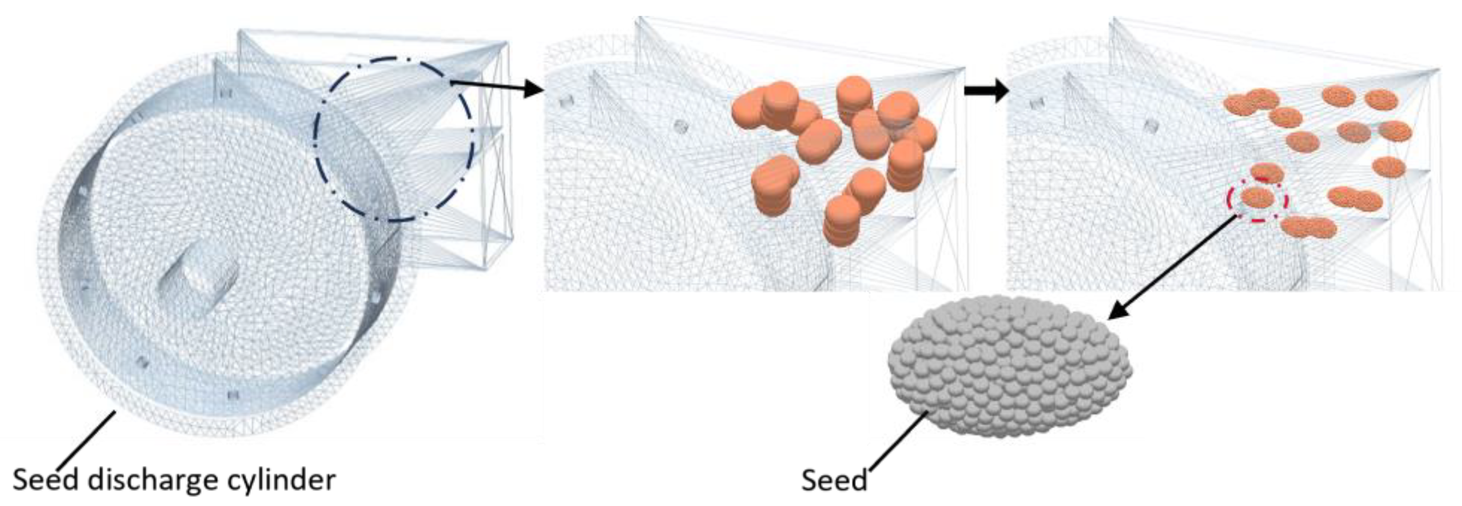
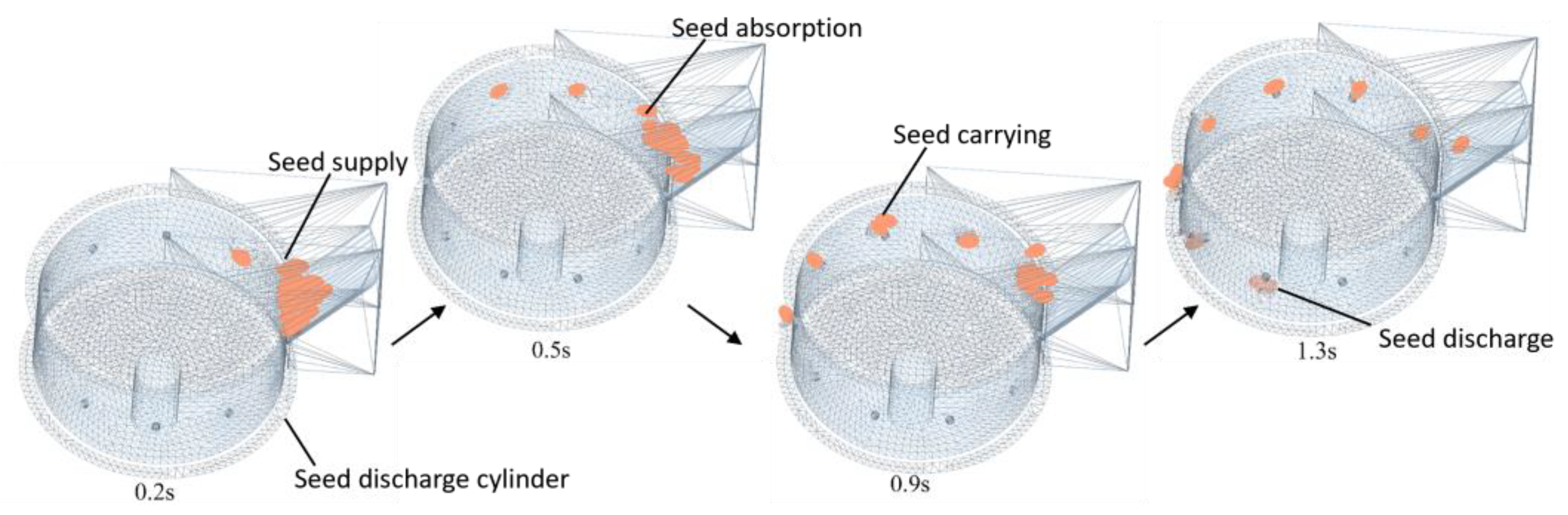
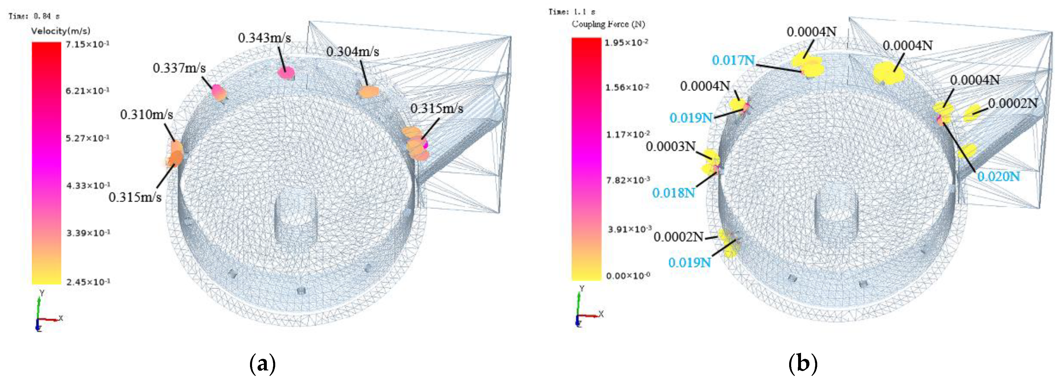
2.7.2. Simulation of Coupling and Results of the Seed Discharging Process

The particles were subjected to gravity, airflow field forces, and the contact forces between the seed and seed discharger during the simulation.
The forces acting on the particles in the airflow field were output in the form of coupling force (Coupling Force). The velocity, displacement, kinetic energy and coupling force of the seed during the simulation were obtained by marking a specific particle. The coupling simulation process is shown in Figure 16.
The particles were marked in the Setup Selections of EDEM to obtain the velocity and coupling force of the seed in the simulation process. As shown in Figure 17, the velocity and coupling force of the seeds at each seed suction hole were more evenly balanced during the coupling process, indicating that the peanut seeds could achieve stable adsorption force under the negative pressure of −5.5 kPa.

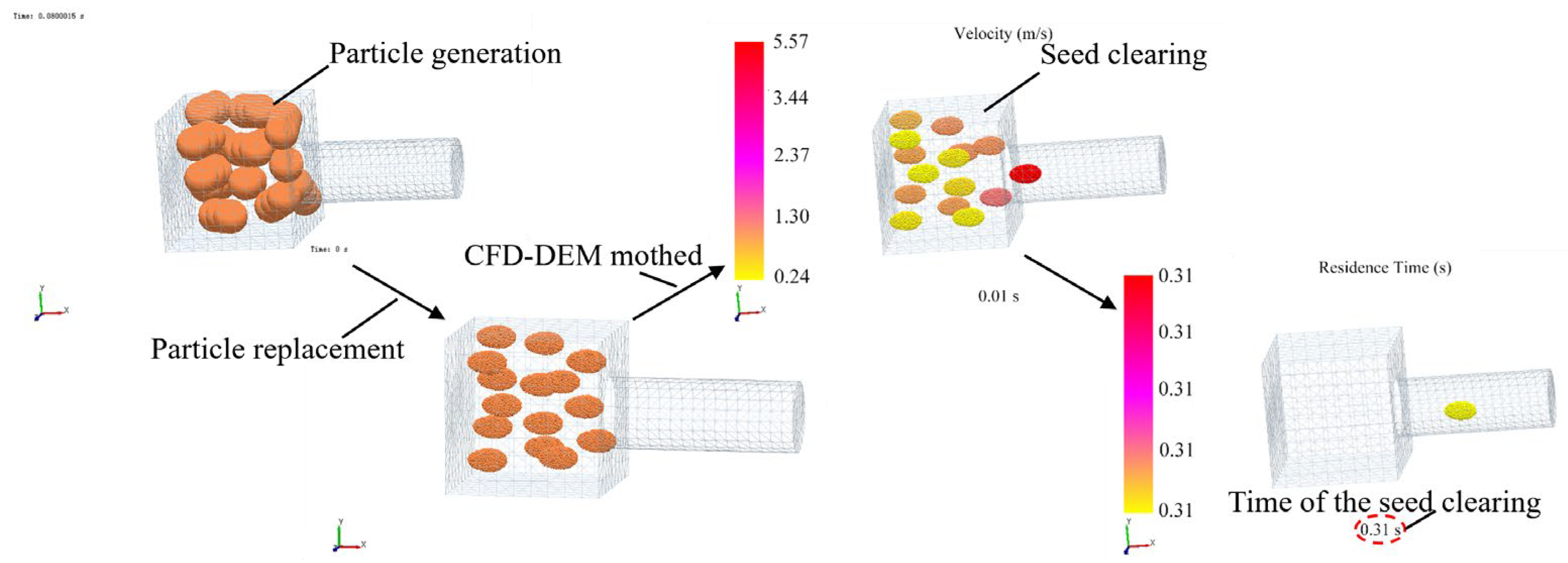
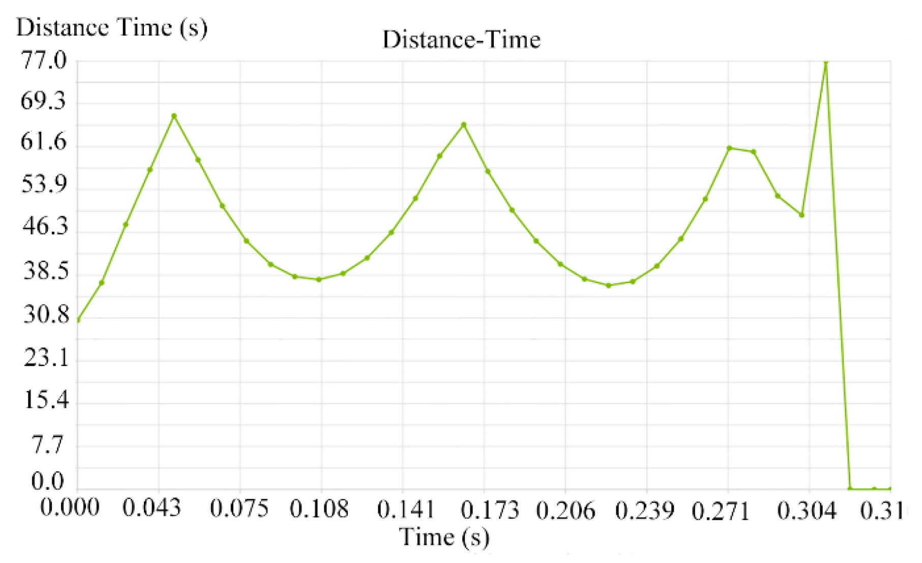
2.7.3. The Coupled Process of the Seed Clearing and Simulation Results

The air suction seed discharger for plot seeding needs to have a seed-clearing function in order to prevent the seed of different varieties from being mixed, and to clear away the remaining seed in time before entering the next plot. The simplified model of the seed-clearing chamber was imported into EDEM, and the coupling simulation was performed as described in the previous coupling method. We set the negative pressure at the outlet to be −4 kPa and used the API to replace the particles. As shown in Figure 18, the seed-clearing device could achieve 100% seed clearing.
The working speed of the plot-breeding planter is 1 m/s and the distance between the plots is 1 m. The last particles are marked in Figure 18. We exported the displacement curve of the particles. As shown in Figure 18, the seeds in the seed-clearing chamber could be completely removed in 0.31 s. The seed-displacement curve is shown in Figure 19. The seed clearing time is less than 1 s, indicating that the seeds of the previous variety can be removed before moving to the next plot.

3. Results and Discussion

3.1. Bench Test Results and Discussion

3.1.1. Preparation and Method of the Test

In order to re-verify the reasonableness of the diameter of the seed suction hole, as well as to obtain the best working negative pressure and working speed, the seed discharger was installed on the JPS-12 seed discharger performance testing bench, as shown in Figure 20. The seed discharger was mounted at one end of the test bench and was driven by a drive motor for seeding. The power of the drive motor was 0.5 kw and it could output 10~150 r/min. Seeds were discharged and fell on the conveyor belt and passed through the measuring device to obtain the sowing performance.
The test process was repeated three times, with 250 seeds being measured each time. The test indicators were calculated according to the national standard of China [25]. The calculation method is shown in Equation (26).
Q = n 1 N × 100 % R = n 2 N × 100 % M = n 3 N × 100 % ,
where n1 is the number of holes with qualified seed spacing; n2 is the number of holes with multiple seeds; n3 is the number of holes without seeds; and N is the total number of holes that are measured.
To obtain the sowing index evaluation standard [26,27], the seeding pass rate needs to be greater than 80%, the reseeding rate needs to be less than 15%, and the leakage rate needs to be less than 8%, as shown in Table 2.

3.1.2. Test Programmes and Results

The seed discharger rotational velocity, working negative pressure, and seed suction hole diameter were selected as the test factors, and the seed spacing pass rate, multiple seeds rate, and seed missing rate were selected as the test indicators to carry out the central composite experimental design. The test results were analysed by Design-Expert 13 software. Five levels were taken for each test factor, as shown in Table 3. The total number of test programmes was 20, and each test was repeated three times to obtain the average value. The test results are shown in Table 4.

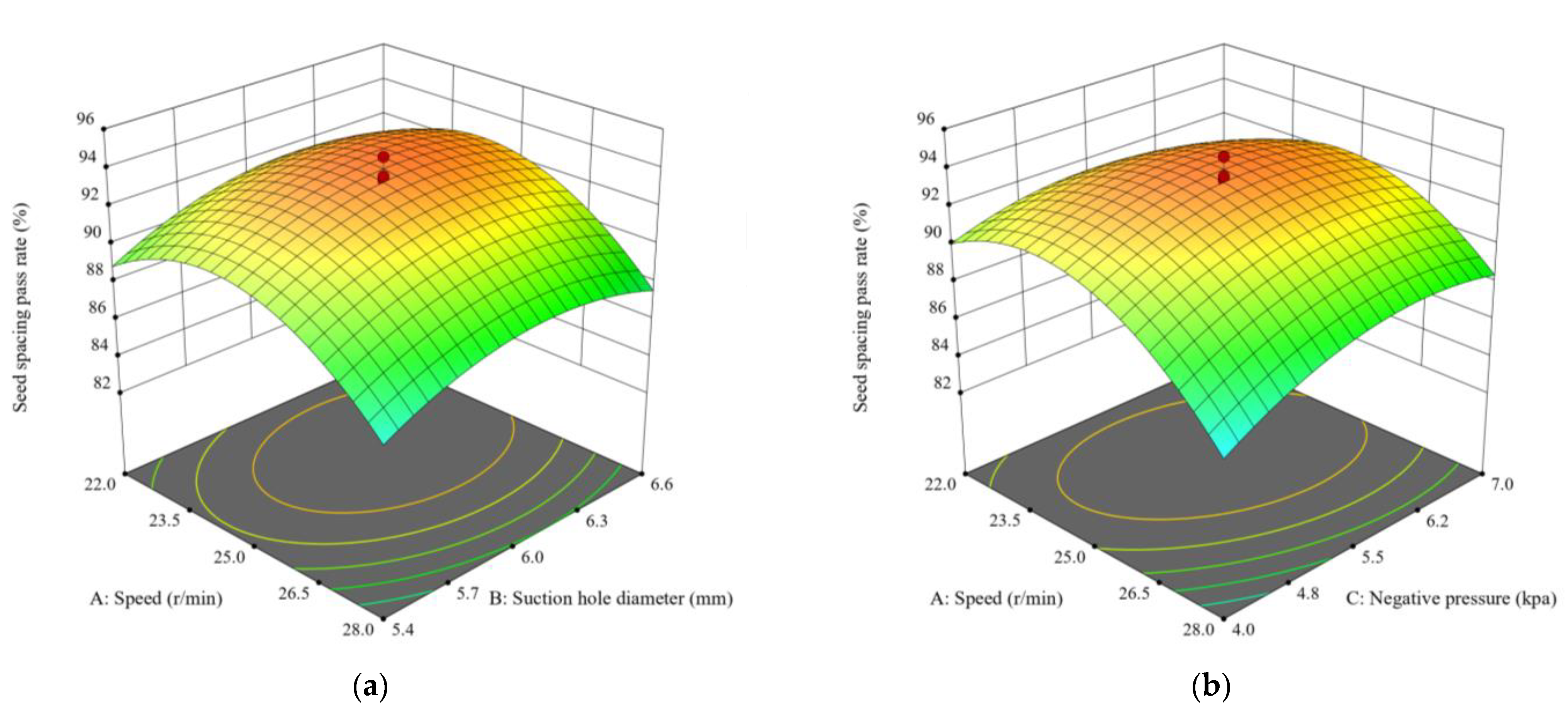
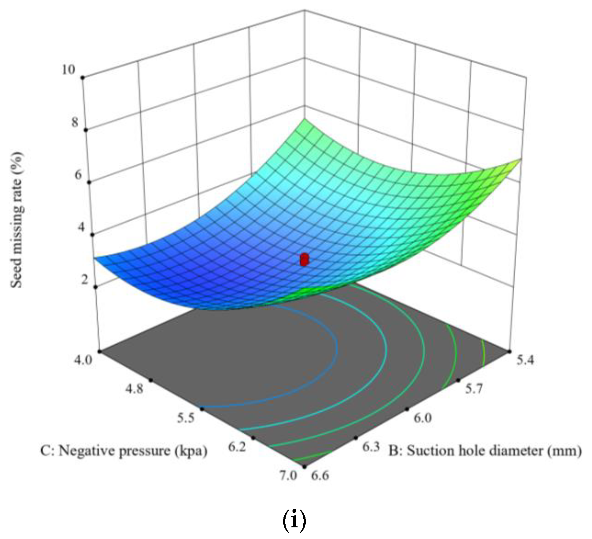
3.1.3. Analysis of the Test Results

The quadratic regression models for seed spacing pass rate, multiple-seed rate, and seed missing rate were developed by Design-Expert 13, respectively. As shown in Table 5, according to the correction coefficient Adjusted R2 of the regression models of the three indicators, it can be seen that the three models can explain 96.85%, 93.75%, and 95.44% of the corresponding changes, respectively. Adeq Precision measures the signal to noise ratio. A ratio greater than 4 is desirable. As can be seen in Table 5, the Adeq Precision values of the three indicators are all bigger than 4, which indicated that all models can be used to navigate their design space. As shown in Table 6, Table 7 and Table 8, according to the ANOVA table for the indicators, the p-value < 0.05, which is shown as significant, and the p-value < 0.01, which is shown as highly significant.
The p-value of the Lack of Fit is 0.2653, which is shown to be insignificant (p > 0.05), indicating that the regression equation is simulated relatively well and the model is accepted. The quadratic regression model for the seed spacing pass rate was obtained as shown in Equation (27).
Q = 305.21 + 17.22 X 1 + 59.03 X 2 + 2.56 X 3 0.07 X 1 X 2 + 0.19 X 1 X 3 + 0.20 X 2 X 3 0.37 X 1 2 4.75 X 2 2 0.73 X 3 2 .
The p-value of the Lack of Fit is 0.5436, which is shown to be insignificant (p > 0.05), indicating that the regression equation is simulated relatively well and the model is accepted. The quadratic regression model for the multiple-seed rate was obtained as shown in Equation (28).
R = 161.78 7.04 X 1 30.20 X 2 + 5.92 X 3 + 0.39 X 1 X 2 0.30 X 1 X 3 0.13 X 2 X 3 + 0.14 X 1 2 + 1.73 X 2 2 + 0.10 X 3 2
The p-value of the Lack of Fit is 0.0522, which is shown to be insignificant (p > 0.05), indicating that the regression equation is simulated relatively well and the model is accepted. The quadratic regression model for the seed missing rate was obtained as shown in Equation (29).
M = 285.29 9.97 X 1 38.67 X 2 13.08 X 3 0.25 X 1 X 2 + 0.20 X 1 X 3 + 0.35 X 2 X 3 + 0.20 X 1 2 + 3.45 X 2 2 + 0.62 X 3 2
The response surfaces of the test factors on the seed spacing pass rate, the multiple-seed rate, and the seed missing rate are shown in Figure 21.
The response surfaces of the seed spacing pass rate are shown in Figure 21a–c. From the figure, it can be seen that the seed spacing pass rate can reach the maximum value when the speed of seed discharger is between 20 and 30 r/min, the diameter of seed suction hole is between 5 and 7 mm, and the working pressure is between 3 and 8 kPa. From the response surface, it can be seen that the effects of the three factors on the seed spacing pass rate can be ranked from largest to smallest: speed > suction hole diameter > negative pressure.
The response surfaces of the multiple-seed rate are shown in Figure 21d–f. From the figure, it can be seen that the multiple-seed rates can reach the minimum value when the speed of the seed discharger is between 20 and 30 r/min, the diameter of seed suction hole is between 5 and 7 mm, and the working pressure is between 3 and 8 kPa. From the response surface, it can be seen that the effects of the three factors on the multiple-seed rate can be ranked from largest to smallest: speed > negative pressure > suction hole diameter.
The response surfaces of the seed missing rate are shown in Figure 21g–i. From the figure, it can be seen that the seed missing rate can reach the minimum value when the speed of the seed discharger is between 20 and 30 r/min, the diameter of seed suction hole is between 5 and 7 mm, and the working pressure is between 3 and 8 kPa. From the response surface, it can be seen that the effects of the three factors on the seed missing pass rate can be ranked from largest to smallest: negative pressure > suction hole diameter > speed.

3.1.4. Final Parameters of the Discharger

We took the seed discharger speed, working negative pressure, and the diameter of the seed suction hole as the influencing factors, and the maximum value of the seed spacing pass rate as the objective function, as shown in Equation (30).
M a x Q s . t . 20 r min 1 X 1 30 r min 1 5   mm X 2 7   mm 3   kpa X 3 8   kpa R 15 % M 8 %
The best optimisation results were obtained by using Design-Expert 13: the seed discharger rotational velocity was 24.38 r/min, the seed suction hole diameter was 5.73 mm, and the working pressure was −6.15 kPa. In order to easily process the device and adjust the working parameters, the diameter of the seed suction hole was set to 6 mm, the working negative pressure as set to 6 kpa, and the working speed was set to 25 r/min. At this time, the performance indexes of the seed discharger were as follows: the seed spacing pass rate was 93.32%, the multiple-seed rate was 3.46%, and the seed missing rate was 3.34%.

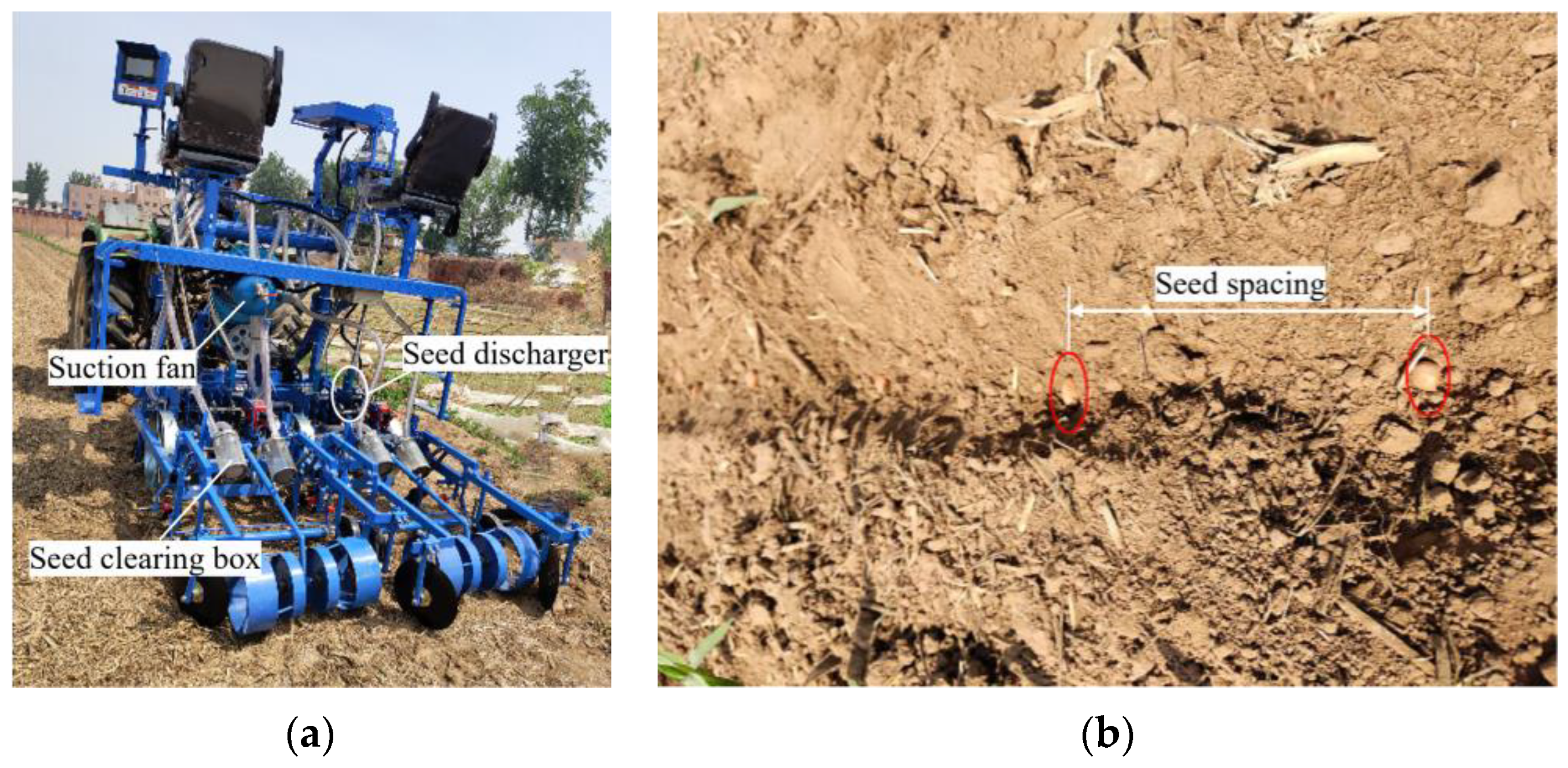
3.2. Field Trial Results and Discussion

In June 2024, the seed discharger was mounted on the planter to test the effectiveness of its sowing process in the field. The total area of the test field was 12 m2, the row length was 5 m, the row spacing was 0.6 m, and the spacing between plots was 1 m. The planter was attached to the rear of a John Deere Skytractor JDT720 tractor, as shown in Figure 22, and the planter was operated at the working speed of 3.6 km/h.
The negative pressure was set to be −6 kPa, the rotational velocity of the seed discharger was 25 r/min, and the diameter of the seed suction hole was 6 mm. The test results were calculated according to GB/T 6973-2005 Test Methods for Single-Grain (Precision) Planters. The test was divided into three groups, and each group was repeated five times. In total, 250 seeds were measured each time, and the average value was taken as the test result.
The test results are shown in Table 9. The seed discharger’s sowing process is good, the seed spacing pass rate is more than 90%, the multiple-seed rate is less than 6%, the seed missing rate is less than 4.5%, and the seed-clearing rate is 100%, which meets the sowing requirements. The 95% confidence intervals for seeding pass rate, multiple-seed rate, and seed missing rate were (88.9557, 93.1777), (3.8137, 6.4597), and (2.1157, 5.4777), respectively.
Comparing the results of the field test and the test bench, the field test, due to the actual working environment, seed variability, and other factors, resulted in the actual seed spacing pass rate being lower than the test result of the test bench. Due to unfavourable effects, such as insufficient absorption of the seed suction hole during the actual sowing process, leads to the lack of seed adsorption, resulting in an increase in the seed missing rate.

4. Conclusions

A seed discharger for peanut plot breeding was designed, and its seed supply, seed carrying, seed discharging, and seed-clearing processes were analysed theoretically.
(1)
Two single stroke cylinders were used for seed replacement and to avoid confusion between different varieties of seeds. The seed supply process was controlled by a seed supply cylinder with a stroke of 40 mm, and the seed-clearing process was controlled by a seed-clearing cylinder with a stroke of 70 mm. The installation angle of the plugging wheel was designed to be 27° and the inclination angle of the seed-clearing plate was designed to be 35°. The diameter of the seed discharge cylinder was designed to be 190 mm, and the number of seed suction holes was designed to be 10.
(2)
The flow field inside the seed discharger was analysed by Fluent R17.0 software. The rotation speed of the seed discharge cylinder was designed in the range of 20~30 r/min, the diameter of the seed suction hole was designed in the range of 5.5–6.5 mm, and the working negative pressure was designed in the range of 5.5–6.5 kPa. The simulation results of the CFD-DEM method showed that the adsorption force at the seed suction hole was about 0.02 N, and the seed clearing time was 0.31 s when the rotation speed of the seed discharge cylinder was 25 r/min, the diameter of the seed suction hole was 6 mm, and the working negative pressure was 5.5 kPa. The seed clearing time was 0.31 s, indicating that the seeds of the previous variety could be removed before moving to the next plot.
(3)
The developed seed discharger was installed on the test bench to carry out the central composite design experiment, and the test results were analysed and optimised with the help of Design-Expert 13 software. The final parameters of the seed discharger were obtained as follows: rotational speed of the seed cylinder was 25 r/min, the diameter of the seed suction hole was 6 mm, and the working negative pressure was −6 kPa. Finally, the seed discharger was tested in the field, and the results showed that the seed spacing pass rate was bigger than 90%, the multiple-seed rate was less than 6%, the seed missing rate was less than 4.5%, and the seed-clearing rate reached 100%, which meets the requirements of peanut plot breeding. Optimisation of the structure allows the seed discharger to meet the operating requirements with as little power consumption as possible.

Author Contributions

Conceptualization, D.R. and X.C.; methodology, X.C.; software, B.L.; validation, D.R., Y.Y. and Z.G.; formal analysis, Y.Y.; investigation, M.L.; resources, B.L.; data curation, M.L.; writing—original draft preparation, X.C.; writing—review and editing, D.R.; visualisation, D.W.; supervision, Z.G.; project administration, D.W.; funding acquisition, D.W. All authors have read and agreed to the published version of the manuscript.

Funding

This research was funded by Key Technologies Research and Development Program (2022YFD2300100) and Key Technology Research and Development Program of Shandong Province (2024LZGC004).

Institutional Review Board Statement

Not applicable.

Data Availability Statement

The original contributions presented in the study are included in the article material, further inquiries can be directed to the corresponding authors.

Conflicts of Interest

The authors declare no conflicts of interest.

References

  1. Wang, Z.; Zhang, Y.; Yan, L.; Chen, Y.; Kang, Y.; Huai, D.; Wang, X.; Liu, K.; Jiang, H.; Lei, Y.; et al. Correlation and variability analysis of yield and quality related traits in different peanut varieties across various ecological zones of China. Oil Crop Sci. 2023, 8, 236–242. [Google Scholar] [CrossRef]
  2. Zhou, X.; Ren, X.; Luo, H.; Huang, L.; Liu, N.; Chen, W.; Lei, Y.; Liao, B.; Jiang, H. Safe conservation and utilization of peanut germplasm resources in the Oil Crops Middle-term Genebank of China. Oil Crop Sci. 2022, 7, 9–13. [Google Scholar] [CrossRef]
  3. Zhao, S.-C.; Lü, J.-L.; Xu, X.-P.; Lin, X.-M.; Luiz, M.R.; Qiu, S.-J.; Ciampitti, I.; He, P. Peanut yield, nutrient uptake and nutrient requirements in different regions of China. J. Integr. Agric. 2021, 20, 2502–2511. [Google Scholar] [CrossRef]
  4. Haro, R.J.; Carrega, W.C.; Otegui, M.E. Row spacing and growth habit in peanut crops: Effects on seed yield determination across environments. Field Crops Res. 2022, 275, 108363. [Google Scholar] [CrossRef]
  5. Zhao, J.; Lai, H.; Bi, C.; Zhao, M.; Liu, Y.; Li, X.; Yang, D. Effects of paclobutrazol application on plant architecture, lodging resistance, photosynthetic characteristics, and peanut yield at different single-seed precise sowing densities. Crop J. 2022, 11, 301–310. [Google Scholar] [CrossRef]
  6. Zhang, J.-L.; Geng, Y.; Guo, F.; Li, X.-G.; Wan, S.-B. Research progress on the mechanism of improving peanut yield by single-seed precision sowing. J. Integr. Agric. 2020, 19, 1919–1927. [Google Scholar] [CrossRef]
  7. Qiu, Y.J.; Li, G.Q.; Zang, X.W.; Liu, J.; Hao, X.; Zhang, J.; Cui, Y.N.; Zhang, P.L.; Liu, B.; Liu, H.J. Research Hotspots and Trends of Groundnut (Arachis hypogaea L.) Breeding and Cultivation Based on Bibliometric Analysis. J. Peanut Sci. 2024, 53, 88–104. [Google Scholar] [CrossRef]
  8. Zhang, Z.Z.; Wang, C.H.; Xia, Y.L.; Mao, J.X.; Wang, Y.; Du, Q.; Yang, H.; You, Y. Evolution analysis of main traits of registered peanut varieties in China from 2020 to 2023. Chin. J. Oil Crop Sci. 2024, 46, 687–696. [Google Scholar] [CrossRef]
  9. Liao, J.H.; Cong, J.L.; You, Y.; Mao, J.X. Research progress of high-oleic acid peanut in China. Cereals Oils 2023, 36, 5–8. Available online: https://kns.cnki.net/kcms2/article/abstract?v=_bj0XFJq-767bRK6yLu8hKTwSGNotieJ0nJIu_ih1-fo6F3vLvwNuNI6zaqr_wUN0_6lqN8luc9210DrRn9E4Wzzqf3dZrSEwwGqpheC88nKTe_e0UYW-zn97px70NjR0nlqJZKg-YPePeX1Uc1FnqTOuBthUJFuSOP2PnXTAXfL0jv90j3eVCKSoq81RLeQbDs9356iN_NEIeKXlXsG9A==&uniplatform=NZKPT (accessed on 18 April 2023).
  10. De Almeida Moreira, B.R.; Marra, T.M.; da Silva, E.A.; de Brito Filho, A.L.; Júnior, M.R.B.; dos Santos, A.F.; da Silva, R.P.; Vellidis, G. Advancements in peanut mechanization: Implications for sustainable agriculture. Agric. Syst. 2024, 215, 103868. [Google Scholar] [CrossRef]
  11. Çiftçi, S.; Suna, G. Functional components of peanuts (Arachis hypogaea L.) and health benefits: A review. Future Foods 2022, 5, 100140. [Google Scholar] [CrossRef]
  12. Qi, B.B.; Cong, J.L.; Zeng, M.J.; Yan, Q.; Hu, R.; Wu, M.C.; Zhu, T. Experimental study on the effect of soaking treatment on peanut seed damage. J. Shihezi Univ. (Nat. Sci.) 2020, 38, 146–154. [Google Scholar] [CrossRef]
  13. Shang, S.Q.; Wu, X.F.; Yang, R.B.; Li, G.Y.; Yang, X.L. Research Status and Prospect of Plot-sowing Equipment and Technology. Trans. Chin. Soc. Agric. Mach. 2021, 52, 1–20. [Google Scholar] [CrossRef]
  14. Ren, D.G.; Wang, D.W.; Li, M.X.; Li, X.; Ma, Z.J.; Dong, T.T.; Chang, X.L.; Ma, S.K.; Yu, H.L. Design and Experiment of Air Suction Seed Metering Device for Alfalfa Plot Breeding. J. Agric. Mech. Res. 2025, 47, 39–45. [Google Scholar] [CrossRef]
  15. Chang, X.L.; Shang, S.Q.; He, X.N.; Li, Y.T.; Liu, J.J.; Li, X.J.; Li, W.J.; Li, Q. Design and Test of Precision Planter for Peanut Community Breeding. J. Agric. Mech. Res. 2025, 7, 1–6. [Google Scholar] [CrossRef]
  16. Hao, J.J.; Qin, J.H.; Yang, S.H.; Ai, Q.H.; Ma, Z.K. Design and experiments of a precision sowing unit with the spoon clip for single peanut seed planting in plot. Trans. Chin. Soc. Agric. Eng. 2023, 39, 33–41. [Google Scholar] [CrossRef]
  17. Liu, B.; Wang, D.W.; Li, X.J.; He, X.N.; Yang, X.C.; Xun, G.S.; Liu, S.M.; Zhao, Z. Simulation and Experiment of Peanut Air Suction Seed Metering Device Based on DEM-CFD Coupling Method. J. Agric. Mech. Res. 2022, 44, 166–172. [Google Scholar] [CrossRef]
  18. Wang, W.W.; Song, L.Z.; Shi, W.B.; Wei, D.H.; Chen, Y.X.; Chen, L.Q. Design and Experiment of Air-suction Double-row Staggered Precision Seed Metering Device for Maize Dense Planting. Trans. Chin. Soc. Agric. Mach. 2024, 55, 53–63. [Google Scholar] [CrossRef]
  19. Li, C.; Zhang, D.X.; Yang, L.; Cui, T.; He, X.T.; Li, Z.M.; Dong, J.Q.; Xing, S.L.; Jiang, Y.Y.; Liang, J.Y. Research on a centrifugal high-speed precision seed metering device for maize with airflow-assisted seed filling and cleaning. Comput. Electron. Agric. 2024, 226, 109434. [Google Scholar] [CrossRef]
  20. Yu, Y.X.; Wang, Y.; Zhou, J.W.; Pan, Y.L. Design and Test of Combined Pumpkin Seed Attitude-constrained Directional Seed Metering Device. Trans. Chin. Soc. Agric. Mach. 2025, 55, 121–132+158. [Google Scholar] [CrossRef]
  21. Shang, Z.Q.; Zhang, K.F.; Yang, D.F.; Ma, Z.P. Simulation optimization of seed plate of air suction soybean seed-metering device based on DEM-CFD coupling. J. Chin. Agric. Mech. 2023, 44, 1–8. [Google Scholar] [CrossRef]
  22. Wang, G.W.; Xia, X.M.; Zhu, Q.H.; Yu, H.Y.; Huang, D.Y. Design and experiment of soybean high-speed precision vacuum seed metering with auxiliary filling structure based on DEM-CFD. J. Jilin Univ. (Eng. Technol. Ed.) 2022, 52, 1208–1221. [Google Scholar] [CrossRef]
  23. Ding, L.; Yang, L.; Zhang, D.X.; Cui, T.; Gao, Y.J. Design and Experiment of Seed Plate of Corn Air Suction Seed Metering Device Based on DEM-CFD. Trans. Chin. Soc. Agric. Mach. 2019, 50, 50–60. [Google Scholar] [CrossRef]
  24. Ding, L.; Yang, L.; Wu, D.H.; Li, D.Y.; Zhang, D.X.; Liu, S.R. Simulation and Experiment of Corn Air Suction Seed Metering Device Based on DEM-CFD Coupling Method. Trans. Chin. Soc. Agric. Mach. 2018, 49, 48–57. [Google Scholar] [CrossRef]
  25. GB/T 6973-2005; Testing Methods of Single Seed Drills (Precision Drills). Machinery Industry Publishing House: Beijing, China, 2005.
  26. JB/T51017-1999; Product Quality Classification of Precision Planters for Mid-Tillage Crops. Machinery Industry Publishing House: Beijing, China, 2000.
  27. JB/T 10293-2013; Specifications for Single Seed Drills (Precision Drills). Machinery Industry Publishing House: Beijing, China, 2013.
Figure 1. (a) Exploded view of the seed discharger. (b) Assembly diagram of the seed discharger. (1) Left support plate. (2) Left end cover. (3) Seed-clearing tube. (4) Seed-clearing device support plate. (5) Bearing. (6) Air suction tube. (7) Seed discharge cylinder. (8) Plug hole wheel. (9) Right seal. (10) Negative pressure connection tube. (11) Chain wheel. (12) Right support plate. (13) Seed supply cylinder. (14) Seed supply tube. (15) Seed-clearing cylinder. (16) Seed-clearing board. (17) Lift seal. (18) Screw.
Agriculture 15 00276 g001
Figure 2. (a) Schematic diagram of the plot breeding trial. (b) Work principle of the seed discharger.
Agriculture 15 00276 g002
Figure 3. (a) Three-dimensional size of the peanut seed. (b) Measurement of material by CTX Mass Tester.
Agriculture 15 00276 g003
Figure 4. Operation principle of seed supply and seed-clearing devices. (a) Status of solenoid valves and cylinders during seed supply. (b) Diagram of the process of generating negative pressure inside the seed discharge cylinder and the air suction tube. (c) Force analysis of the seed on the seed clearing board.
Agriculture 15 00276 g004
Figure 5. Theoretical analysis of the seed absorption process.
Agriculture 15 00276 g005
Figure 6. (a) Structure diagram of the hole plugging wheel. (b) Force on the seed when it leaves the suction hole. (c) Trajectory of the seed after it loses suction force.
Agriculture 15 00276 g006
Figure 7. (a) Seed carrying status with the angle of β in the range of 0° to 90°. (b) Seed carrying status with the angle of β in the range of 90° to 180°. (c) Seed carrying status with the angle of β in the range of 180° to 270°. (d) Seed carrying status with the angle of β in the range of 270° to 297°.
Agriculture 15 00276 g007
Figure 8. The mesh of the airflow field.
Agriculture 15 00276 g008
Figure 9. (a) The flow field at the seed suction hole diameter of 5.5 mm. (b) The flow field at the seed suction hole diameter of 6 mm. (c) The flow field at the seed suction hole diameter of 6.5 mm.
Agriculture 15 00276 g009
Figure 10. The flow field at the seed suction hole diameter of 6 mm.
Agriculture 15 00276 g010
Figure 11. (a) The flow field at the rotational speed of 20 r/min. (b) The flow field at the rotational speed of 25 r/min. (c) The flow field at the rotational speed of 30 r/min.
Agriculture 15 00276 g011
Figure 12. (a) The flow field at the rotational speed of 20 r/min. (b) The flow field at the rotational speed of 25 r/min. (c) The flow field at the rotational speed of 30 r/min.
Agriculture 15 00276 g012
Figure 13. (a) The flow field at the negative pressure of −4 kPa. (b) The flow field at the negative pressure of −5.5 kPa. (c) The flow field at the negative pressure of −7 kPa.
Agriculture 15 00276 g013
Figure 14. (a) The flow field at the negative pressure of −4 kPa. (b) The flow field at the negative pressure of −5.5 kPa. (c) The flow field at the negative pressure of −7 kPa.
Agriculture 15 00276 g014
Figure 15. Peanut seed simulation model and the discrete particle model of the seed metering device.
Agriculture 15 00276 g015
Figure 16. Coupled simulation of the seed discharge process.
Agriculture 15 00276 g016
Figure 17. (a) Velocity of the seed in the coupled field. (b) The suction force on the seed in the coupled field.
Agriculture 15 00276 g017
Figure 18. The coupling simulation process of seed clearing.
Agriculture 15 00276 g018
Figure 19. Clear seed simulation analysis diagram.
Agriculture 15 00276 g019
Figure 20. (a) Test bench of the seed metering device. (b) Installation position of the seed discharger.
Agriculture 15 00276 g020
Figure 21. (a) Response surface between seed spacing pass rate and speed as well as seed suction hole diameter. (b) Response surface between seed spacing pass rate and speed as well as negative pressure. (c) Response surface between multiple-seed rate and negative pressure as well as seed suction hole diameter. (d) Response surface between multiple-seed rate and speed as well as seed suction hole diameter. (e) Response surface between multiple-seed rate and speed as well as negative pressure. (f) Response surface between multiple-seed rate and negative pressure as well as seed suction hole diameter. (g) Response surface between seed missing rate and speed as well as seed suction hole diameter. (h) Response surface between seed missing rate and speed as well as negative pressure. (i) Response surface between seed missing rate and negative pressure as well as seed suction hole diameter.
Agriculture 15 00276 g021aAgriculture 15 00276 g021bAgriculture 15 00276 g021c
Figure 22. (a) Installation position of the seed discharger on the planter. (b) The spacing between seeds.
Agriculture 15 00276 g022
Table 1. Material parameters and contact parameters of peanut and the seed discharger.
VariableParametersUnit
Mean length of peanut seeds19.23mm
Mean width of peanut seeds9.67mm
Mean thickness of peanut seeds8.50mm
Density of peanut seeds860kg·m−3
Density of the seed discharger (stainless steel)7850kg·m−3
Poisson’s ratio of peanut seeds0.25\
Poisson’s ratio of the seed discharger0.33\
Elastic modulus of peanut seeds6 × 107Pa
Elastic modulus of the seed discharger (stainless steel)2 × 10¹¹Pa
The static friction coefficient between seed and seed0.50\
The static friction coefficient between the seed and the seed discharger0.30\
The dynamic friction coefficient between seed and seed0.04\
The dynamic friction coefficient between the seed and the seed discharger0.05\
Elastic collision recovery coefficient between seed and seed0.10\
Elastic collision recovery coefficient between the seed and the seed discharger0.40\
Table 2. Evaluation criteria for seeding indicators.
PerformancePerformance Indicator
Seed Spacing ≤ 10 cmSeed Spacing > 10~20 cmSeed Spacing > 20~30 cm
seed spacing pass rate≥60%≥75%≥80%
multiple-seed rate≤30%≤20%≤15%
seed missing rate≤15%≤10%≤8%
Table 3. Coding of factor level.
Code ValueSpeed/r·min−1Suction Hole Diameter/mmNegative Pressure/kPa
−r (−1.682)205−3
−1 Level225.5−4
0 Level256−5.5
+1 Level286.5−7
+r (1.682)307−8
Table 4. Test results.
Test
Programmes
Test FactorsTest Indicators
Speed
X1/r·min−1
Suction Hole Diameter
X2/mm
Negative Pressure
X3/kPa
Seed Spacing Pass Rate
Q/%
Multiple-Seed Rate
R/%
Seed Missing Rate
M/%
1225.5−488.65.67.8
2285.5−483.211.55.3
3226.5−489.53.66.9
4286.5−484.112.72.2
5225.5−787.24.28.6
6285.5−785.65.39.1
7226.5−789.32.28.5
8286.5−786.75.67.7
9206−5.585.54.39.2
10306−5.582.810.17.1
11255−5.586.85.78.5
12257−5.590.35.14.6
13256−387.36.56.2
14256−890.22.17.7
15256−5.594.62.43
16256−5.593.43.92.6
17256−5.592.55.22.3
18256−5.592.853.2
19256−5.592.94.13
20256−5.593.63.62.8
Table 5. Fit Statistics of indicators.
IndicatorStd. Dev.MeanC.V.%R2Adjusted R2Predicted R2Adeq Precision
Seed spacing pass rate0.893388.841.010.96850.94010.828818.2962
Multiple-seed rate0.99205.4418.250.93750.88120.726914.3484
Seed missing rate0.76335.8113.130.95440.91330.678011.9932
Table 6. ANOVA analysis of seed spacing pass rate.
SourceSum of SquaresdfF-Valuep-Value
Model245.11934.13<0.0001
X1-Speed27.96135.030.0001
X2-Suction hole diameter8.68110.870.0080
X3-Negative pressure5.0216.290.0311
X1X20.125010.15660.7006
X1X35.4416.820.0259
X2X30.245010.30700.5917
X12150.861189.03<0.0001
X2240.66150.95<0.0001
X3237.31146.75<0.0001
Residual7.9810
Lack of Fit5.1451.810.2653
Pure Error2.845
Cor Total253.0919
Table 7. ANOVA analysis of multiple-seed rate.
SourceSum of SquaresdfF-Valuep-Value
Model147.60916.67<0.0001
X1-Speed62.67163.68<0.0001
X2-Suction hole diameter0.901610.91620.3610
X3-Negative pressure40.44141.09<0.0001
X1X23.7813.840.0784
X1X313.78114.000.0038
X2X30.101210.10290.7550
X1222.43122.800.0008
X225.3915.470.0414
X320.712810.72430.4146
Residual9.8410
Lack of Fit4.6750.90220.5436
Pure Error5.175
Cor Total157.4519
Table 8. ANOVA analysis of seed missing rate.
SourceSum of SquaresdfF-Valuep-Value
Model121.90923.25<0.0001
X1-Speed8.91115.300.0029
X2-Suction hole diameter10.65118.280.0016
X3-Negative pressure14.81125.430.0005
X1X21.5312.630.1360
X1X35.95110.220.0096
X2X30.781311.340.2738
X1245.98178.93<0.0001
X2221.47136.850.0001
X3226.73145.89<0.0001
Residual5.8310
Lack of Fit5.30510.030.0522
Pure Error0.52835
Cor Total121.90923.25<0.0001
Table 9. Field test results.
ProgrammesSeed Spacing Pass Rate/%Multiple-Seed Rate/%Seed Missing Rate/%Seed-Clearing Rate/%
Test 191.44.554.05100
Test 290.15.594.31100
Test 391.75.273.03100
Confidence interval91.0667 ± 2.1115.1367 ± 1.3233.7967 ± 1.681100
Disclaimer/Publisher’s Note: The statements, opinions and data contained in all publications are solely those of the individual author(s) and contributor(s) and not of MDPI and/or the editor(s). MDPI and/or the editor(s) disclaim responsibility for any injury to people or property resulting from any ideas, methods, instructions or products referred to in the content.

