Article

Design and Experimental Validation of Stem-Clamping-and-Pull-Out-Type Pepper Plug Seedling-Picking Mechanism

1
School of Agricultural Engineering, Jiangsu University, Zhenjiang 212013, China
2
College of Engineering, Northeast Agricultural University, Harbin 150030, China
*
Author to whom correspondence should be addressed.
Agriculture 2025, 15(14), 1563; https://doi.org/10.3390/agriculture15141563
Submission received: 18 June 2025 / Revised: 16 July 2025 / Accepted: 19 July 2025 / Published: 21 July 2025
(This article belongs to the Section Agricultural Technology)

Abstract

As a core component of a fully automatic pepper transplanter, the performance of the seedling-picking mechanism is of particular significance. However, existing seedling-picking mechanisms have problems such as being prone to damaging the seedling roots and substrate, as well as having poor stability. To develop a highly efficient, stable, and minimally damaging seedling-picking mechanism, this study proposed a design scheme for a stem-clamping-and-pulling-out-type seedling-picking end actuator driven by a non-circular gear system. The specific methods and objectives include the following: (1) designing a differential non-circular gear system to replicate a manual picking trajectory accurately; (2) establishing a kinematic model and developing optimization software to determine the optimal parameter combination; (3) experimentally validating the mechanism’s performance through virtual simulations and bench tests. The bench tests showed that the mechanism could complete two seedling-picking operations per rotation, extracting an entire row (eight plants) in a single rotation at a speed of 30 r/min. The measured angles of the end effector at four key postures were highly consistent with simulation and high-speed camera data, with all key posture errors less than 1°. These results demonstrate the mechanism’s high accuracy, efficiency, and reliability.

1. Introduction

Pepper, as an important cash crop, with edible, medicinal, and industrial value, is rich in capsaicin, capsanthin, and other components, serving as a key raw material for food processing and pharmaceutical manufacturing [1,2,3]. Seedling transplantation represents the mainstream planting method for pepper, significantly enhancing survival rates, controlling pests and diseases, and increasing yields [4,5,6]. Transplantation methods are classified into three categories: manual, semi-automatic, and fully automatic. Manual transplantation relies entirely on human labor; some processes in semi-automatic transplantation are mechanized; fully automatic transplantation achieves mechanization throughout the entire process of seedling picking and planting [7]. Currently, pepper transplantation predominantly employs semi-automatic methods, which restricts improvements in production efficiency [8,9]. Mechanical transplantation offers significant advantages, including improved quality, reduced costs, and enhanced efficiency. Fully automatic seedling-picking technology serves as the core indicator for evaluating the degree of automation in transplantation machinery [10,11,12]. In recent years, optimization of seedling-picking mechanism designs has primarily focused on increasing the rate of seedling picking, improving reliability, and minimizing seedling damage. The Italian Urbinati RW32 transplanter achieves an operational rate of 36,000 plants per hour. The Ferrari Futura model, which integrates photoelectric sensing technology, has a theoretical capacity of 3720 plants per hour. However, its precision pneumatic system exhibits instability, and the equipment is complex and costly, limiting its promotion in areas with complex terrain [13]. The five-bar slide rail device developed by Choi et al. in South Korea demonstrates a high operational success rate but suffers from cumulative phase errors, making it unsuitable for high-speed scenarios [14]. The Japanese Yanmar PW10N duckbill transplanter features a high degree of automation [15], while the Seikan PVPHR2 semi-automatic transplanter ensures upright planting through a spatial seven-link mechanism [16]. Both systems encounter challenges such as high costs and limited efficiency improvements. Young Bong Min et al. developed a push-out onion plug seedling-picking mechanism to fulfill the requirements of mechanized transplanting for onions. They investigated the push-out resistance and root breakage rate of seedlings under different pin diameters and operational speeds, and found that the push-out resistance increased as the diameter of the push-out pin increased [17]. Md Nafiul Islam et al. designed a seedling-picking mechanism composed of gears, cams, and crank–slider combinations. The linear picking trajectory of the mechanism is realized by a gear-driven crank–slider mechanism, and the swing of the picking arm is controlled by a cam. The mechanism exhibits significant vibration and low picking efficiency when operating at high speed [18]. Md Zafar Iqbal et al. designed a pepper seedling-picking mechanism using a gear train, which enables fast and accurate transplanting of seedlings with low power consumption, through kinematic analysis, virtual simulation, and experimental research [19,20]. K. Rahul et al. designed a seedling-picking device based on mechatronic technology, which effectively reduces energy consumption and improves operational efficiency during the picking process [21]. Abhijit Khadatkar et al. developed a gripper-type seedling-picking mechanism, in which the opening, closing, and releasing of the picking mechanism are controlled by a PLC control system. However, it is only suitable for greenhouse operations and the operation quality is relatively low [22]. Chen Jianneng et al. improved the modified elliptical gear–seven-bar transplanting mechanism, optimizing the transplanting trajectory, yet it remains semi-automatic equipment [23]. Yu Gaohong et al. developed an eight-row synchronous transplanting mechanism utilizing non-uniform planetary gear trains to enhance efficiency but encountered issues related to structural redundancy and synchronization errors [24]. Yin Daqing et al. developed an ejection push pot-type seedling-picking mechanism that integrates clamping and pushing functions. This method of retrieving seedlings by clamping the substrate tends to cause root and stem damage as well as looseness of the substrate [25]. Yuan Ting et al. developed a pneumatic vibration seedling-picking-and-planting mechanism, achieving a high picking success rate and low seedling damage rate. However, this mechanism exhibits high dependency on specific trays and seedling cultivation methods, thereby limiting its broader application [26].
Overall, the current transplanting devices have issues such as susceptibility to damaging seedling roots and substrate and poor stability [27]. To address these challenges, this study proposes a novel stem-clamping-and-pull-out method based on a non-circular gear system to accurately replicate the manual seedling-picking motion while minimizing damage to the substrate and root system. This approach aims to provide robust technical support for fully automatic pepper transplanters, thereby advancing large-scale cultivation.

2. Materials and Methods

2.1. Design Requirements for the Seedling-Picking Mechanism

To achieve full automation of the seedling-picking mechanism, this study, grounded in the principle of human bionics, analyzed the motion posture of manual seedling picking, extracted the spatial characteristic parameters of seedling-picking postures, and constructed a mechanized seedling-picking path-planning model. During manual seedling picking, upper limb movements exhibit the typical characteristics of a 2R open-chain mechanism: with the shoulder joint as the fixed pivot, the hand precisely executes a series of actions, including “pulling out seedlings—transporting seedlings—releasing seedlings—resetting”, through the flexion and extension of the elbow joint.
Conventional seedling-picking mechanisms, which constrain the movement of the end effector via rod or slide mechanisms, suffer from limitations such as a narrow resolution range, restricted design space, and insufficient motion accuracy, making it challenging to meet the high-precision requirements for reproducing mechanized picking postures. This study innovatively employs a 2R open-chain mechanism constrained by a non-circular gear train, significantly expanding the mechanism’s operational domain and enabling precise reproduction of specific trajectories and postures. In this mechanism, the crank evolves into a non-circular gear train, while the swing rod transforms into an end effector actuator for seedling retrieval. These components are structurally coupled to form a stem clip–picking-type pepper plug seedling-picking mechanism. This composite drive system strictly adheres to the motion posture required by the pepper-transplanting process and accurately performs the entire sequence of “pulling-out seedlings—transporting seedlings—releasing seedlings—resetting” for picking and planting.

2.2. Composition and Working Principle of the Mechanism

A structural diagram of the stem-clamping-and-pull-out-type pepper plug seedling-picking mechanism is presented in Figure 1. The design layout incorporates a right-side power input structure. Specifically, the right side of the bevel gear transmission box is connected to the stem-clamping-and-pull-out-type pepper plug seedling-extraction mechanism. External power is transmitted to the differential non-circular gear train of the seedling-extraction mechanism via the output shaft of the bevel gear box and the jaw and toothed coupling. This transmission drives the non-circular gear train sun gear and the shell of the non-circular gear train assembly to operate at different speeds.
The stem-clamping-and-pulling-out-type pepper plug seedling-picking mechanism’s core transmission components include the shell of the gearbox, sun gear, intermediate gears I–IV, planetary gears I–II, intermediate shafts I–IV, planetary shafts I–II, and upper/lower seedling-picking end effectors, as well as the seedling-jacking execution components. The intermediate gears I–IV are fixed to their corresponding intermediate shafts, with each intermediate shaft supported by double lateral heart bearings and hinged to the shell of the gearbox. The left ends of planetary shafts I/II are integrated with planetary gears I/II, while the right end is hinged to the rotating support secondary arm. The connection between the left shell of the gearbox and the right rotating support secondary arm via the planetary shafts I/II forms a rotating frame, which substantially enhances the overall mechanical performance of the stem-clamping-and-pulling-out-type seedling-picking mechanism.
Inside the non-circular gear train, the sun gear engages in first-level meshing with intermediate gears I and III on both sides. Intermediate gear I forms a second-level meshing connection with both the sun gear and intermediate gear II. The upper and lower surfaces of intermediate gear II engage with planetary gear I and intermediate gear I, respectively. Intermediate gear III meshes with the sun gear and intermediate gear IV, while intermediate gear IV connects with planetary gear II and intermediate gear III, thereby forming a closed-loop transmission structure. Within this configuration, the sun gear drives planetary gears I and II to rotate, transmitting motion synchronously via the upper and lower planetary shafts to the upper and lower seedling-picking end actuators, causing the actuators to rotate around the planetary axes. When the planetary carrier (the shell of the non-circular gear train) is driven counterclockwise by the power input shaft of the bevel gearbox, the intermediate shafts I–IV and planetary shafts I–II within it simultaneously undergo rotational motion, driving the transplanting arm assembly to achieve rotational movement. Ultimately, the seedling-picking end effector, under the combined influence of the planetary axis rotation and the revolution of the shell of the non-circular gear train, reproduces the predetermined motion trajectory and spatial postures.
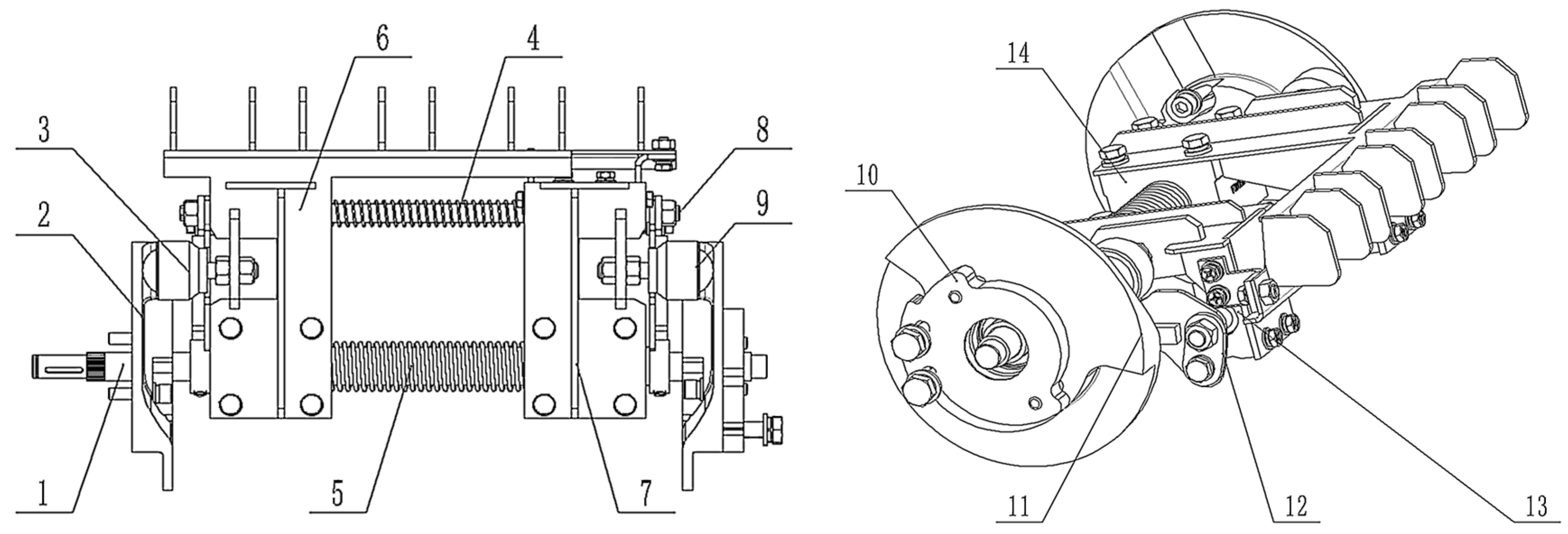
As the core component of the stem-clamping-and-pulling-out-type pepper transplanting mechanism, during the transplanting process, the stem-clamping-and-pulling-out end actuator must precisely execute a series of consecutive actions, including clamping, pulling, transporting, and releasing the seedlings. As shown in Figure 2, the end effector designed in this study primarily consists of planetary shafts, left and right end face cams, compression springs, universal balls, sliders, and guide rods. Among these components, the planetary shaft and the small slider guide shaft function as rails to provide guidance for the actuator’s movement. The side end face cams control the opening and closing of the actuator. During the picking process, when the picking mechanism reaches the picking point, the universal ball within the actuator, in conjunction with the compression spring, ensures tight contact with the two end face cams. As the mechanism moves, the universal ball transitions from the concave surface to the convex surface of the end face cam, driving the actuator to complete the clamping action. In the seedling transport phase, the universal ball remains in contact with the convex surface of the end face cam to maintain stable seedling clamping. When the release mechanism reaches the release point, the universal ball rolls back to the concave surface of the end face cam. Under the force exerted by the compression spring, the upper and lower clamping plates rapidly open to perform the release action.

2.3. Kinematic Analysis

Select the center of rotation O1 of the sun gear as the origin of the coordinate system to establish the kinematic equation for the seedling-picking mechanism. Through theoretical derivation and numerical computation, the rotation angle parameters of each non-circular gear pair in the transmission system, the spatial coordinate parameters of the rotation centers, and the tip-position parameters of the seedling-picking actuator can be determined (Figure 3).
During the operation of the transplanting device, the sun gear assembly and the planetary gearbox, serving as prime movers, rotate at a constant counterclockwise speed. Counterclockwise rotation is defined as positive, while clockwise rotation is defined as negative. When the planetary gearbox completes an angular displacement of i , the relative rotation angle of each non-circular gear with respect to the planetary carrier is denoted as θ k h i , and its absolute rotation angle of motion is defined as φ k i . According to the topological numbering rule of the transmission chain, k = 1 to 4 correspond respectively to the sun gear, intermediate gear 1, intermediate gear 2, and planetary gears.
Planetary carrier rotation angle i :
i = ω t
The sun gear rotates counterclockwise in the same direction relative to the planetary carrier at twice the speed, and the absolute rotation angle of the sun gear is
φ 1 i = f a i H 0 + 2 i
The absolute rotation angle of the intermediate gear 1 is
φ 2 i = f a i H 0 + θ 2 h i
where θ 2 h i = θ 2 h i 1 + θ 1 i θ 1 i 1 r 1 i o 1 o 2 r 1 i
The absolute rotation angle of the intermediate gear 2 is
φ 3 i = f a i H 0 ( 180 α 1 ) θ 3 ( θ 30 ) θ 3 h i
where θ 3 h i = θ 3 h i 1 + θ 2 h i θ 2 h i 1 r 2 i o 2 o 3 r 2 i
The absolute rotation angle of the planetary gear 1 is
φ 4 i = f a i H 0 ( 180 α 1 ) ( 180 α 2 ) + θ 2 h θ 40 + θ 4 h i
where θ 4 h i = θ 4 h i 1 + θ 3 h i θ 3 h i 1 r 3 i o 3 o 4 r 3 i
Coordinates of the relative motion of the tip of the upper seedling-picking arm:
x D 1 i = x o 4 i + S c o s φ 0 + δ H 0 180 α 1 180 α 2 + θ 2 h θ 40 + θ 4 h i y D 1 i = y o 4 i + S s i n φ 0 + δ H 0 180 α 1 180 α 2 + θ 2 h θ 40 + θ 4 h i

2.4. Trajectory and Posture Analysis

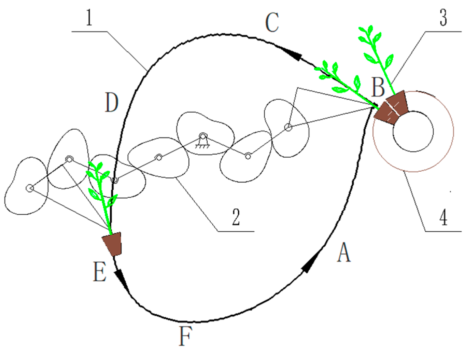
In response to the issue of damage to the substrate and root system of pepper plug seedlings caused by the insertion-based picking method, this study mimicked manual picking actions to reproduce the trajectory and posture of hand-pulling pepper stems during transplantation, as shown in Figure 4.
When the stem-clamping-and-pulling-type seedling-picking mechanism is in operation, the end effector for picking seedlings is required to pass through several expected posture points in sequence and run continuously and stably along the predetermined trajectory and posture. When the pepper transplanter is working normally, a fixed installation angle is set between the seedling box and the frame, and the seedling-picking mechanism is kept at a specific installation distance from the seedling box. When the seedling-picking mechanism moves smoothly from point A to point B, the end effector reaches about 3 mm above the root of the pepper plug seedlings. At this point, the end effector for picking seedlings closes quickly, the seedlings are pulled out and detached from the tray along the growth direction of the plug seedlings, and it then moves to point C. The entire process of transitioning from point A to the picking point B, where the seedlings are picked up, followed by pulling and transporting them to point C, is defined as the picking stage.
The process by which the seedling-picking mechanism picks up the pepper plug seedlings and runs from point C, the end of pulling out seedlings, through point D, the intermediate point, to point E, the starting point of planting seedlings, is defined as the seedling transportation stage. During this process, the universal ball bearings are always in contact with the protruding working surface of the end face cam, and the clamping plates remain clamped to hold the plug seedlings in place. During the seedling transportation stage, it is required that the actuator at the end of the seedling picking move smoothly with small speed fluctuations to prevent the plug seedlings from falling during transportation.
The stocking seedlings stage begins when the seedling-picking mechanism moves from the starting point E to the ending point F. During this process, the universal ball rolls along the protruding working surface of the end face cam to the concave area, and the upper and lower clamping components inside the actuator at the end of the picking are rapidly opened to both sides under the force of the compression spring, releasing the clamping plate from the clamping state. The pepper plug seedlings fall vertically into the seedling-separation device under the force of gravity, and then the field transplanting operation is completed through the planting device.
The process during which the seedling-picking mechanism returns from point F (the termination point) to point A (the initial point) is defined as the return stage. During this stage, the universal ball remains in close contact with the concave area of the end face cam under the action of the compression spring, ensuring that the clamping plate of the actuator at the end of the seedling-picking mechanism stays open. To enhance the transplanting efficiency of pepper plug seedlings, it is necessary for the transplanting arm to reset quickly during the return stage, preparing for the next cycle of seedling picking.

2.5. Optimization Design Software Development and Parameter Optimization

The process of picking pepper plug seedlings using the stem-clamping-and-pulling-out-type mechanism consists of four core steps: clipping the seedlings, transporting the seedlings, releasing the seedlings, and resetting the mechanism. The process of clamping the seedlings must ensure the integrity of the seedlings while avoiding mechanical damage. During the seedling delivery stage, the motion trajectory should remain smooth to prevent interference or collisions between mechanism components. Additionally, precision is critical during the seedling-release stage to ensure that the seedlings in the tray enter the seedling distribution device vertically. The reset action requires a rapid response to prepare for subsequent seedling-picking operations. For this purpose, eight optimization objectives were set in this study:
(1)
The actuator components at the end of the seedling picking do not interfere with each other;
(2)
The end effector for picking seedlings does not interfere with the seedling box;
(3)
Seedling-picking angle θ 1 [ 310 ° , 340 ° ] ;
(4)
Seedling-throwing angle δ 1 [ 270 ° , 310 ° ] ;
(5)
Angle difference α [ 50 ° , 60 ° ] ;
(6)
The height of the picking trajectory is greater than 250 mm;
(7)
The non-circular gear module is greater than 2.5 mm;
(8)
The planetary gear does not damage the seedlings.
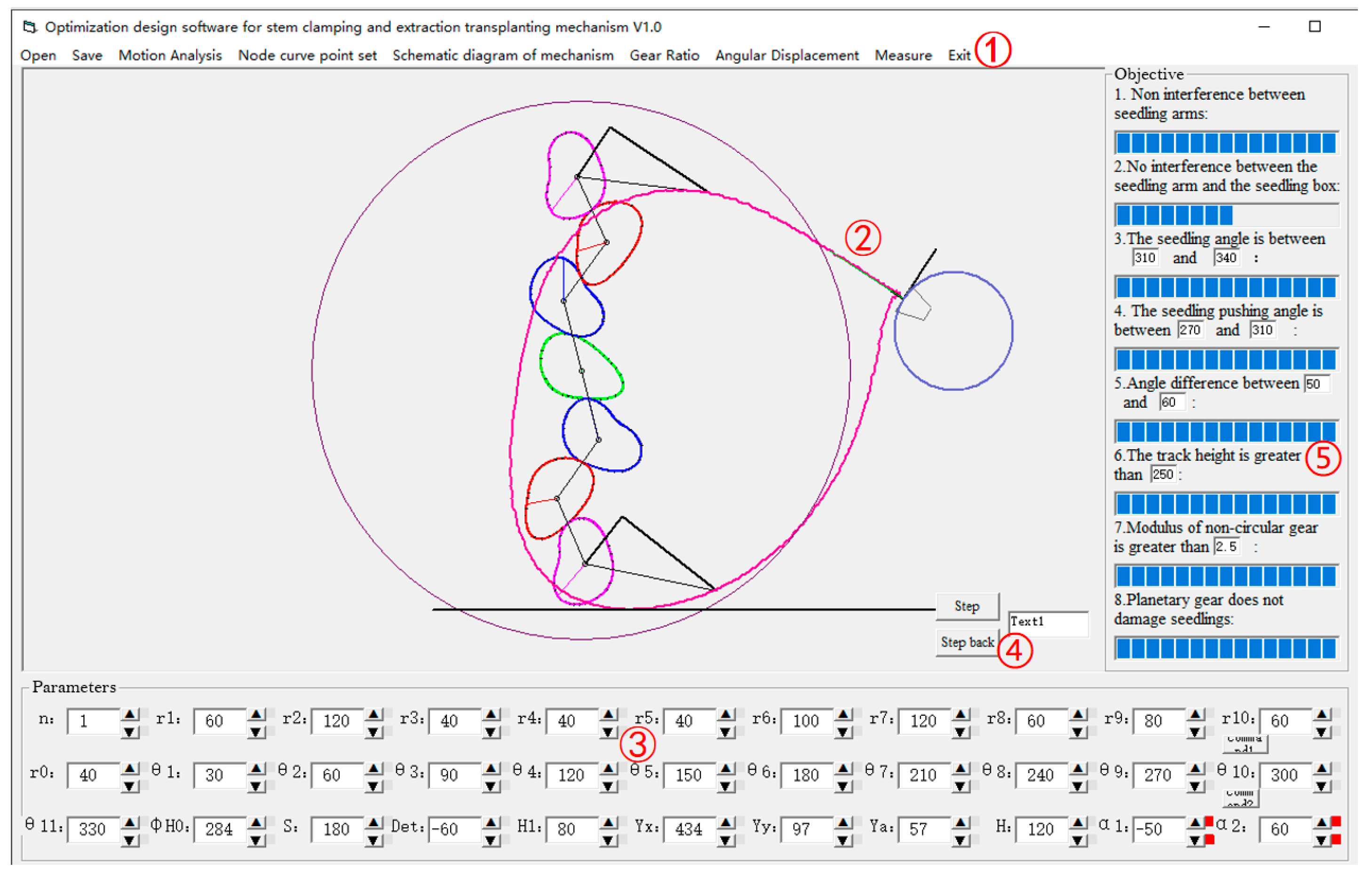
The optimization design software for the stem-clamping-and-pulling-out picking mechanism integrates 22 geometric parameters of non-circular gear pitch curves and 11 configuration parameters of the seedling-picking mechanism, forming a composite optimization space with 33 design variables. Based on the human–machine collaborative optimization framework, a combined optimization model using the genetic algorithm and human–machine interaction was employed to obtain the optimal solution set for eight performance indicators. The results of the parameter configuration optimization are presented in Table 1 (Figure 5).
Parameter definition description:
(1)
The radial component of the sun gear pitch curve in the polar coordinate system is denoted as r 0 r 10 ;
(2)
The corresponding polar angle parameter of the sun gear pitch curve in the polar coordinate system is marked as θ 1 θ 11 ;
(3)
The initial assembly azimuth angle of the planetary carrier assembly in the seedling-picking device is defined as H 0 ;
(4)
The initial phase angle of the end effector unit is denoted as Det;
(5)
The spatial distance from the center of planetary rotation to the tip of the clamp is characterized as S;
(6)
The distance between the inflection point of the terminal picking mechanism and the axis of the planetary gear is described by the parameter H 1 ;
(7)
The abscissa of the seedling box in the rectangular coordinate system is denoted as YX;
(8)
The ordinate of the seedling box in the rectangular coordinate system is denoted as Yy;
(9)
The inclination angle of the seedling box is denoted as Ya;
(10)
The single-row spacing indicator for plug seedling-planting operations is determined by the H parameter;
(11)
The first corner of the planet carrier is denoted as ɑ1;
(12)
The second corner of the planet carrier is denoted as ɑ2.

2.6. The Influence of the Main Parameters on the Trajectory of the Seedling-Picking Mechanism

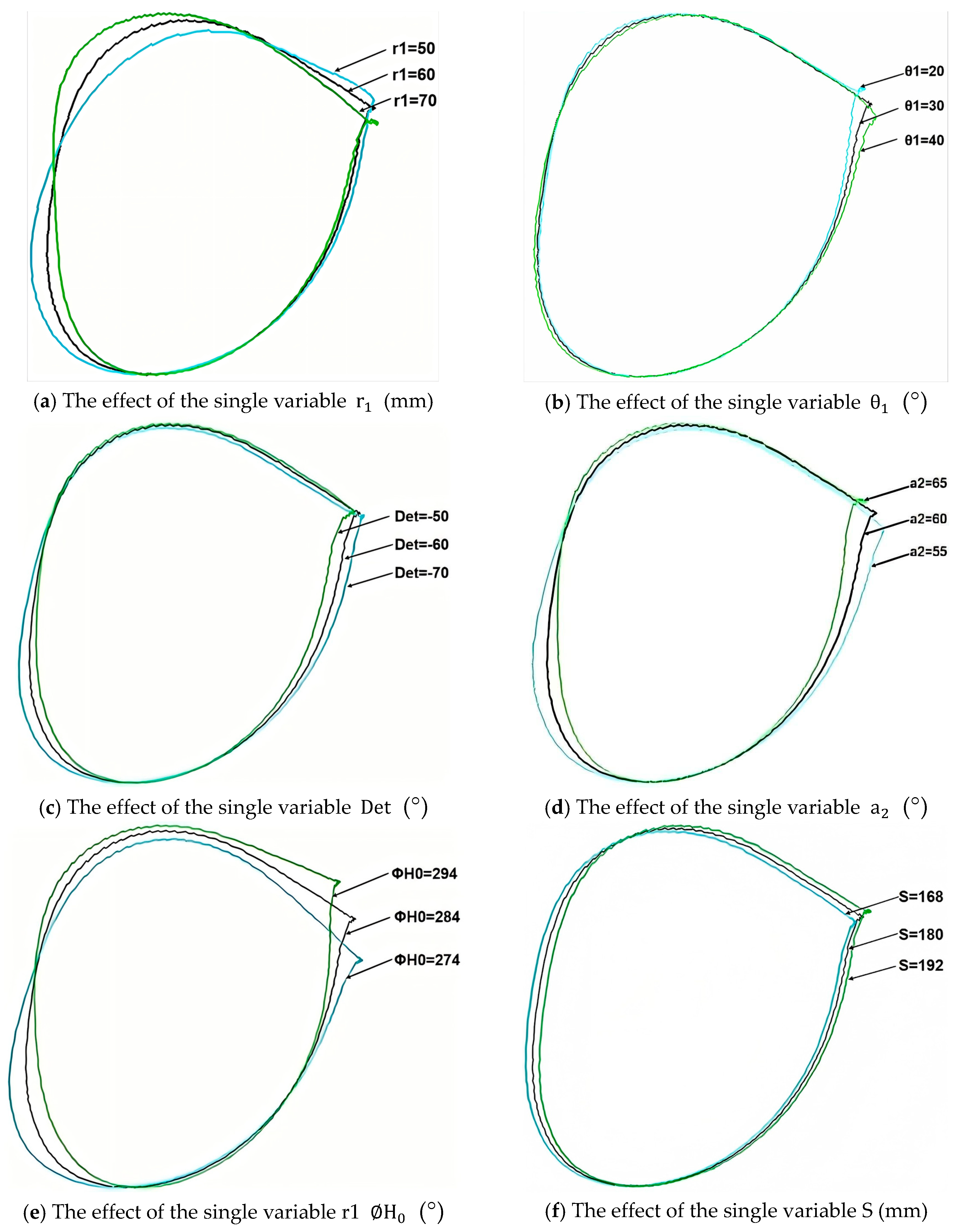
A parameter system comprising 8 design indicators and 33 associated variables was constructed in the optimization design software for the stem-clamping-and-pulling-out picking mechanism. There exists a significant multi-factor coupling relationship between each optimization objective and parameter variable, and the regulatory effects of different design parameters on the mechanism’s performance exhibit marked differences. To enhance the optimization efficiency of the stem-clamping-and-pulling-out-type pepper plug seedling-picking mechanism, a single-variable control strategy was employed for parameter sensitivity analysis in this study.
(1)
The response relationship of r 1 to the optimization objective of the seedling-picking mechanism
As shown in Figure 6a, an increase in the polar diameter of the sun gear-type value point r 1 leads to a vertical offset of the picking point, an increase in the picking angle, and a forward displacement of the throwing point. This is accompanied by a reduction in the throwing angle, resulting in an increase in the trajectory height and an expansion of the angular difference. Additionally, the increase in r 1 makes the loop trajectory of the picking point more pronounced, which may cause stem breakage and negatively affect the transplanting quality. However, when the number of teeth remains constant, an increase in r 1 corresponds to an increase in the module, which can enhance the anti-fracture performance of the gear pair.
(2)
The response relationship of θ 1 to the optimization objective of the seedling-picking mechanism
As shown in Figure 6b, an increase in θ 1 results in a vertical downward shift of the seedling-picking point, an increase in the seedling-picking angle, and a backward displacement of the seedling-throwing point. Simultaneously, the seedling-throwing angle exhibits a negative decrease, ultimately leading to an enlargement in the angular difference and an upward trend in the trajectory elevation. At this stage, the seedling-picking rail moves closer to the right-hand seedling box, increasing the likelihood of interference with the seedling box, which may cause damage to the seedling tray and substrate.
(3)
The response relationship of D e t to the optimization objective of the seedling-picking mechanism
As shown in Figure 6c, as the value of D e t increases, the seedling-picking position shifts laterally to the left, with a corresponding increase in the seedling-picking angle. Simultaneously, the seedling feeding point shifts laterally to the right, and the seedling feeding angle also increases, thereby leading to an increase in the operational distance between the picking mechanism and the seedling box. In this condition, the relative distance between the end effector and the tray becomes greater, which raises the likelihood of clamping failure.
(4)
The response relationship of a 2 to the optimization objective of the seedling-picking mechanism
As shown in Figure 6d, as the corner a 2 of the planetary carrier increases, the seedling-picking point moves upward, leading to a counterclockwise deflection in the overall picking trajectory. This change results in an increased distance between the seedling-picking point and the seedling box, a corresponding reduction in the seedling-picking angle, and challenges for the seedling-picking plate to accurately grasp the root of the pepper plug seedlings.
(5)
The response relationship of H 0 to the optimization objective of the seedling-picking mechanism
As shown in Figure 6e, an increase in the initial installation angle H 0 of the planetary carrier causes the picking trajectory to rotate negatively around the axis, resulting in an increase in the vertical offset of the picking position. As H 0 continues to increase, the risk of collision in the seedling-picking mechanism increases. At the same time, the seedling feeding point moves laterally to the right and the release angle decreases negatively. When H 0 reaches 294°, the seedling feeding point deviates from the axis of the seedling separation device, the plant is less upright, and the verticality of the seedling is lost.
(6)
The response relationship of S to the optimization objective of the seedling-picking mechanism
As shown in Figure 6f, an increase in the value of S leads to an increase in the vertical displacement of the seedling-picking point and an increase in the seedling-picking angle. At this time, the distance between the transmission box and the seedling box decreases, resulting in an increase in the overlap rate between the circumferential rotation of the seedling-picking mechanism and the seedling delivery operation space, and a significant increase in the risk of mechanical interference.

3. Results

3.1. Virtual Simulation Experiment

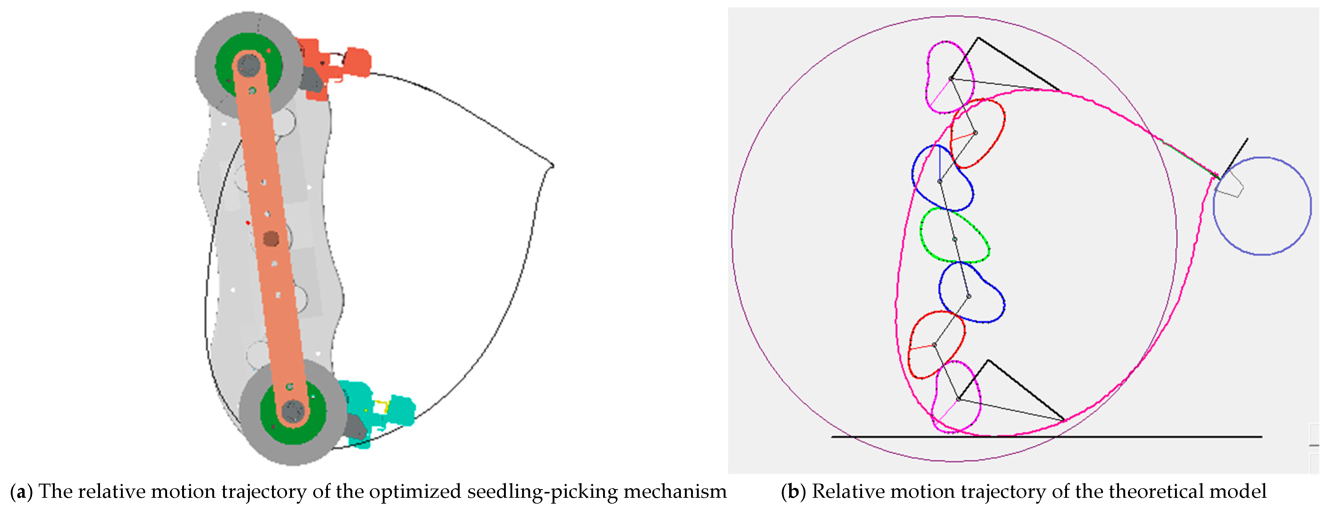
Based on the optimized mechanism parameters, a virtual prototype of the stem-clamping-and-pulling-out-type pepper plug seedling-picking mechanism was established to complete the virtual simulation experiment. The movement trajectory of the seedling-picking mechanism was obtained through virtual simulation. By comparison, the working trajectory and posture obtained from the virtual simulation were basically consistent with the results of the optimization design software, mutually verifying the correctness of the kinematic analysis, optimization design software, and virtual simulation.
In the virtual simulation test environment, the planetary carrier rotates at 30 r/min, and the sun gear rotates at 60 r/min. Upon completion of the simulation, the motion data of the trajectory-marking point at the end of the seedling-picking mechanism was extracted to generate the simulation trajectory curve presented in Figure 7a. The following critical indicators can be validated through visual analysis: the interference state of the mechanism’s motion, the meshing accuracy of the non-circular gear, and the pose accuracy of the actuator at the end of the seedling-picking process. A comparison between the simulation trajectory and the theoretical trajectory generated by the optimization design software Figure 7b revealed a high degree of spatial consistency between the two, confirming the equivalence of the virtual prototype model to the theoretical model. These comparison results effectively validated the correctness of both the structural design scheme and the numerical model, providing robust theoretical support for the subsequent physical prototype trial production.
The realization of the seedling-picking mechanism’s function not only requires the precise reproduction of the ideal seedling-picking trajectory but also ensures that the end effector for seedling picking can continuously execute a series of transplanting actions, including clamping and picking seedlings, stable transportation of seedlings, precise placement of seedlings, and quick reset. To comprehensively validate the mechanism’s performance, this study integrated the seedling delivery mechanism, the seedling-picking mechanism, and the seedling feeding mechanism for simulation. The final assembly model of the pepper seedling-delivery seedling-picking seedling-feeding mechanism is presented in Figure 8.
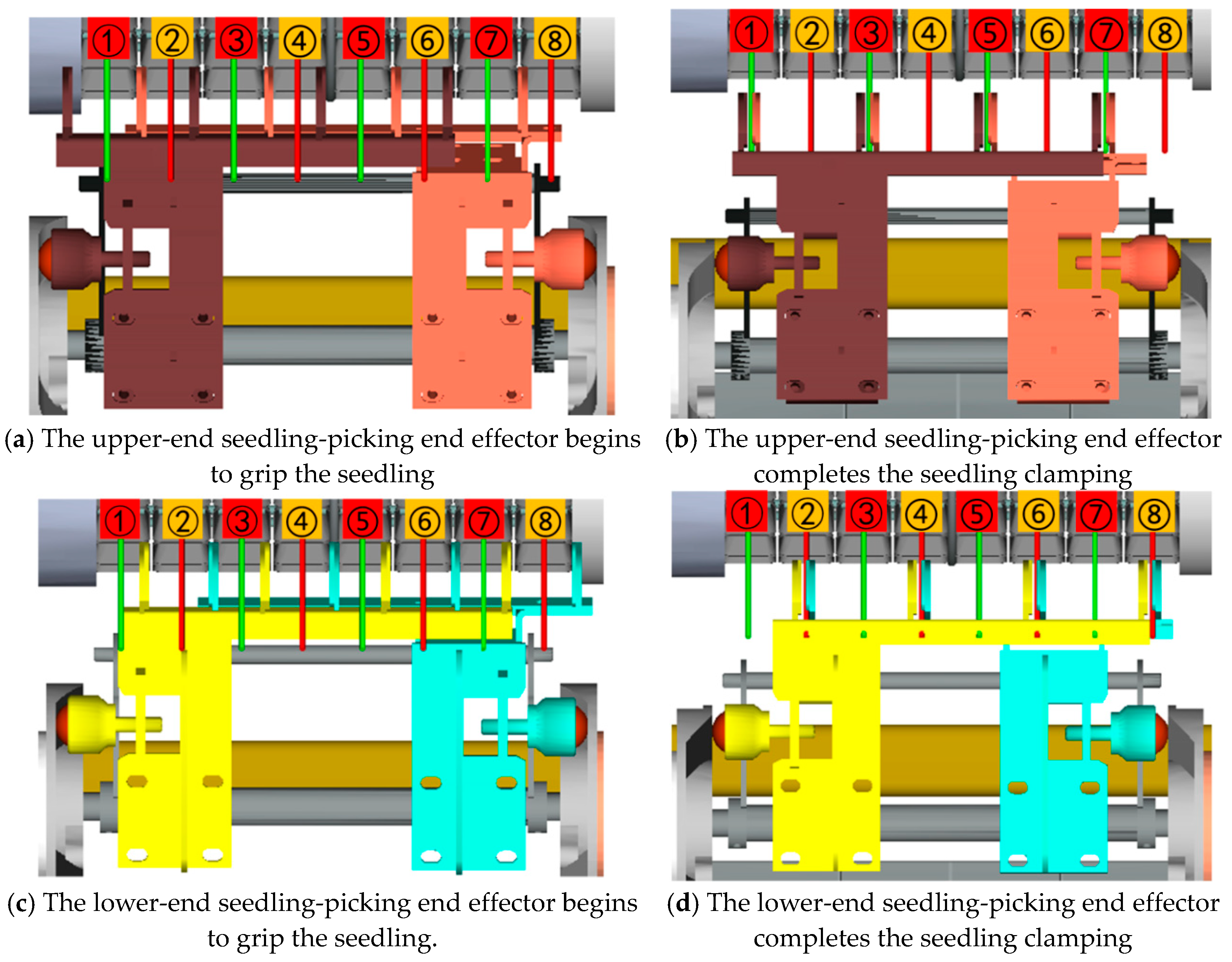
The simulation results show that the seedling-picking mechanism, seedling-feeding mechanism, and seedling-delivery mechanism of the stem-clamping-and-pulling-out-type pepper plug seedlings operate in coordination without interference, and the working sequence of each component was precisely coordinated. The end effector for picking seedlings can precisely perform the action of picking and planting. It was tested whether the clamping center of the clip was perfectly aligned with the target clamping point of the tray, verifying the effectiveness of the mechanism design. The process of picking seedlings with the upper and lower end effectors is shown in Figure 9. In the upper end of the end actuator for picking seedlings (Figure 9a), the upper and lower clamping components are marked in brown and red, respectively, and the pepper plate seedlings corresponding to the picking point (1, 3, 5, 7) are marked in green. At the beginning stage of picking, the universal balls of the upper and lower clamping assembly are tightly attached to the concave surface of the end face cam, and the clamping plates are opened to the maximum extent, with all four pepper plug seedlings in the center positions of the two sets of clamping plates. As the universal balls rotate to contact the convex surface of the end face cam, the clamping plate synchronously moves the center of the guide rod, precisely adhering to the outer surface of the cylinder of the pepper plug seedlings, and firmly clamping the seedlings at the center of the clamping plate, successfully completing the seedling-picking action. Similarly, the upper and lower clamping components of the lower end of the end effector for seedling picking (Figure 9c,d) are distinguished by different colors, and the seedling-picking point (2, 4, 6, 8) is marked in red. The entire process of picking seedlings was smooth and coherent, the trajectory of picking seedlings was highly consistent with the design expectation, and the effect of picking seedlings reached the pre-set technical indicators, fully verifying the reliability and practicality of the mechanism.

3.2. Pose Verification Experiment

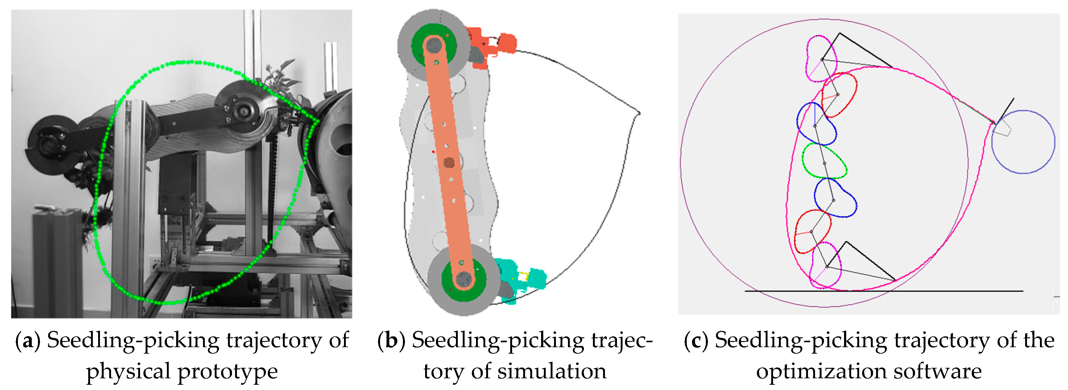
The I-SPEED3 high-speed camera was employed to capture images of the entire rotation cycle of the transplanting mechanism at all times, as shown in Figure 10. Figure 10a illustrates the movement trajectory of the tip of the seedling-clamping plate of the end effector for seedling picking, as measured by the high-speed camera; Figure 10b presents the corresponding trajectory generated by the simulation of the virtual prototype model in the ADAMS 2020 software; Figure 10c depicts the relative motion trajectory of the tip of the seedling-clamping plate calculated based on the theoretical model in the optimization software. Through comparison and analysis, it was determined that the three trajectories exhibited a high degree of consistency. This result effectively validated the accuracy and reliability of the physical prototype, the three-dimensional simulation model, and the kinematic model derived from the optimization design software for the stem-clamping-and-pulling-out-type pepper plug seedling-picking mechanism.
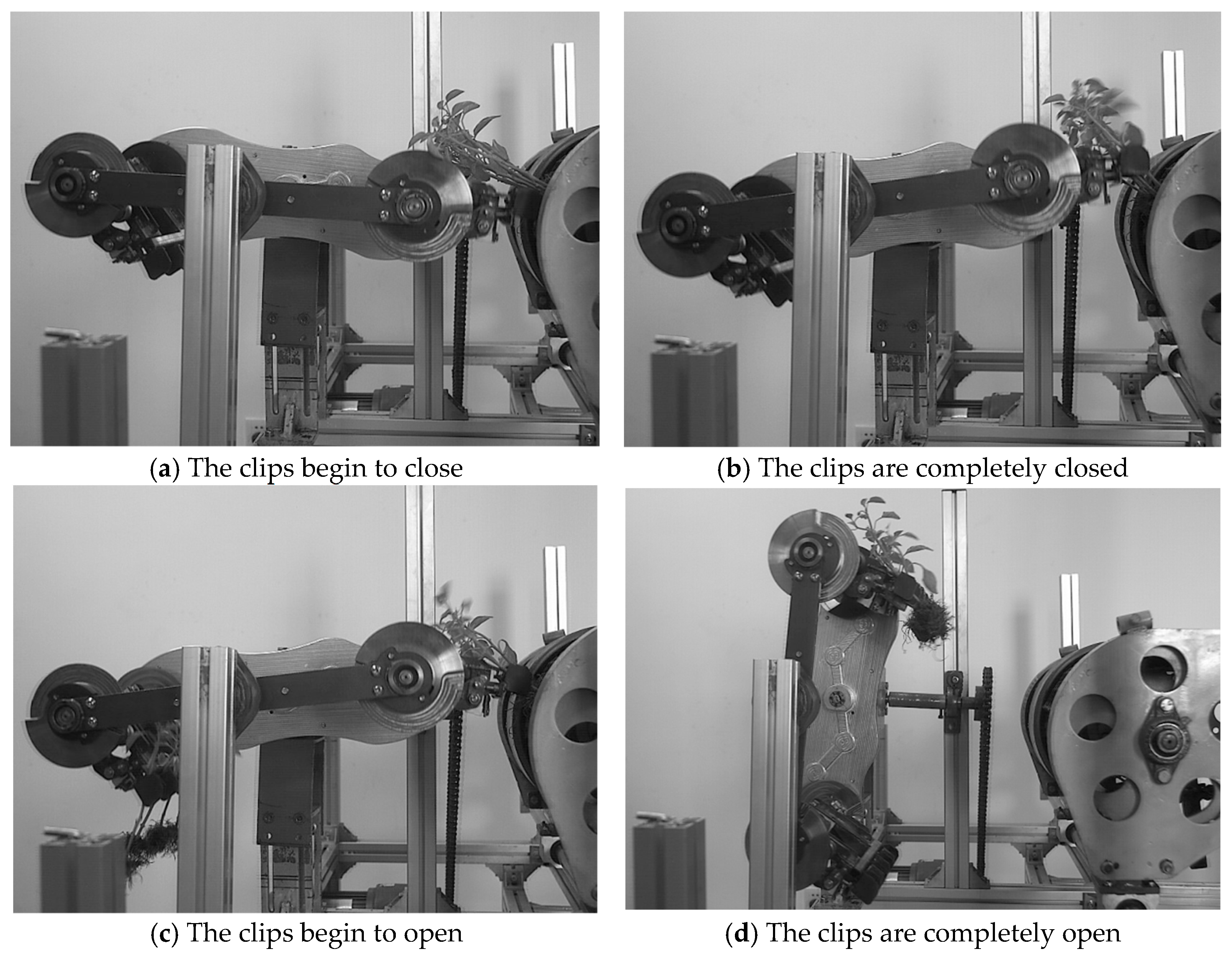
Four critical postures of the seedling-picking mechanism during one rotation cycle were captured, and the postures of the seedling-picking end effector at the initiation of clip closing, complete clip closure, initiation of clip opening, and complete clip opening were recorded, respectively, as shown in Figure 11. The angles of the clamping plates relative to the horizontal direction at different states, as recorded by the high-speed camera, are summarized in Table 2.

3.3. Seedling-Picking Test

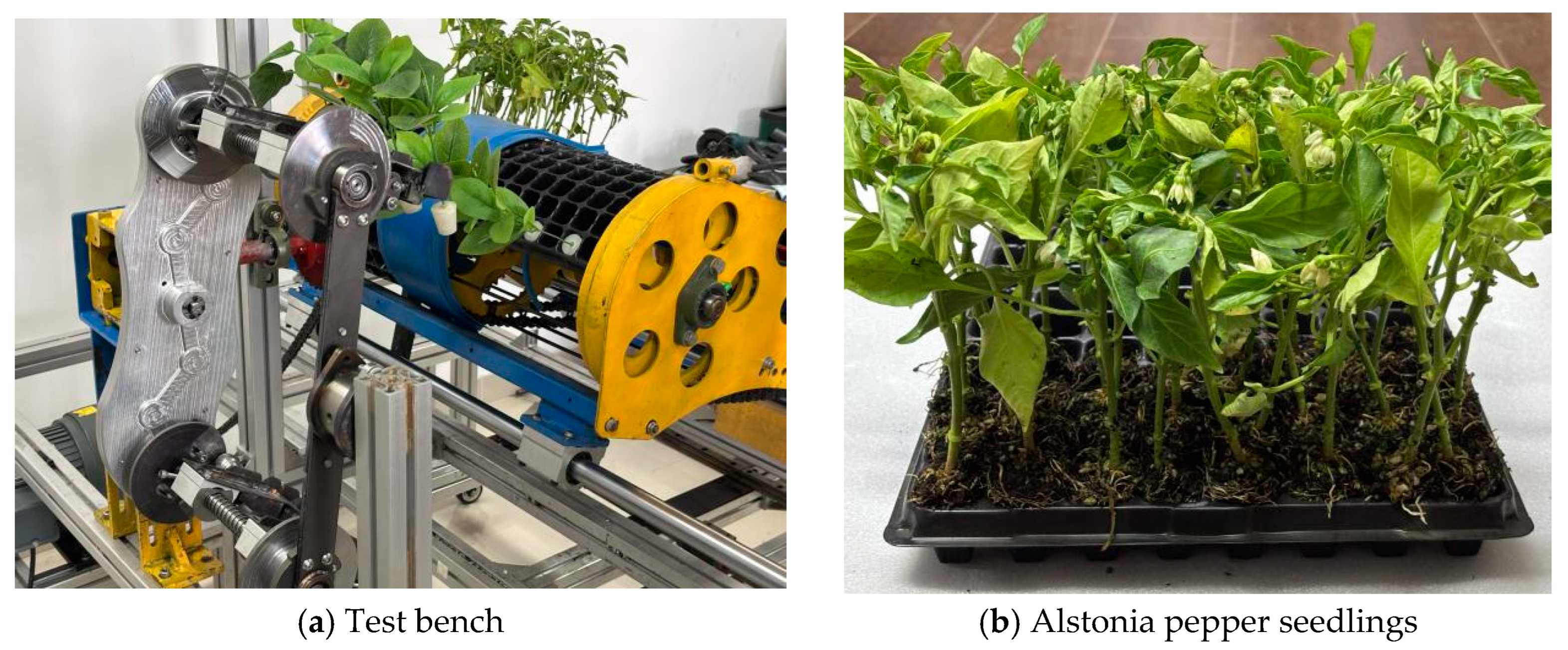
In this study, Alstonia pepper was selected as the test material (Figure 12b), and the plug seedlings were raised for 30 days. The tray size was 8 × 16, with an upper diameter of 30 mm × 30 mm. The angle and position of the seedling trays were adjusted to align with the spatial position of the seedling-picking point of the seedling-picking mechanism, and the rotational speed of the seedling-picking mechanism was set at 30 r/min to lay the foundation for subsequent data collection and performance analysis. The test bench is shown in Figure 12a.
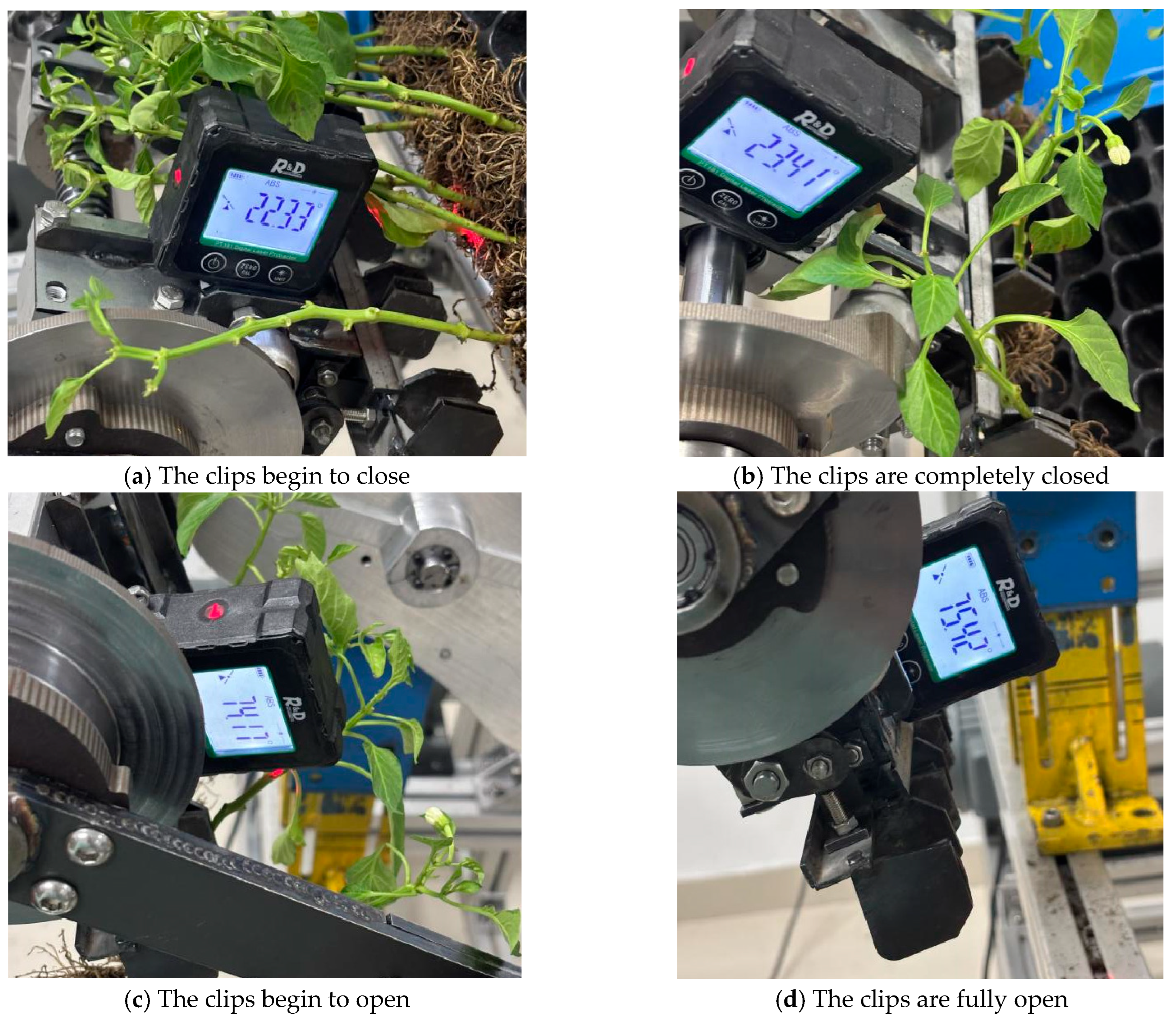
The seedling-picking mechanism developed in this study is capable of performing two seedling-picking operations per full rotation. A single rotation can complete the extraction of an entire row of seedlings (eight plants), thereby significantly enhancing the efficiency of the seedling-picking process. To further investigate the kinematic characteristics of the mechanism, a laser-angle meter was employed to measure the angles corresponding to four critical postures of the end effector during the entire operational cycle. During the seedling-picking experiment, the following data were obtained: when the clamping plates began to close, the digital laser angle meter measured the angle between the clamping plates and the horizontal direction as 22.33° (equivalent to 337.67°); when the clamping plates were fully closed, the angle was 23.41° (equivalent to 336.59°); when the clamping plates started to open, the angle between the clamping plates and the horizontal direction reached 74.17° (equivalent to 285.83°); and when the clamping plates were fully open, the measured angle was 75.42° (equivalent to 284.58°) (Figure 13).
The measured angles were summarized and compared with the angle data from the optimization software and the high-speed camera, as shown in Table 3. The high-speed camera test and the bench seedling-picking test showed that the actual motion of the seedling-picking mechanism angle was consistent with the simulation and theoretical data, and the key pose error of the seedling-picking end actuator was less than 1°, verifying the reliability of the mechanism design.
Through a systematic analysis of the data from the seedling-picking test, it is known that the designed seedling-picking mechanism can fully carry out a series of action processes including seedling picking, transportation, feeding, and resetting. Through comparison and verification, the posture performance of the end effector for picking seedlings at the key positions of picking seedlings is highly consistent with the simulation results of the optimized software and the data from the high-speed camera test. The results fully demonstrate that the design scheme of the stem-clamping-and-pulling-out-type pepper plug seedling-picking mechanism is not only feasible at the theoretical level, but also shows good practicality and reliability in practical application scenarios, providing a solid practical basis for subsequent engineering applications.

4. Conclusions

This study introduces a novel stem-clamping-and-pulling-out method for picking seedlings, which is based on a non-circular gear system. By employing a double-end collaborative operation, the system effectively replicates a manual seedling-picking trajectory through the non-uniform transmission characteristics of the non-circular gears. The clamping of the seedling stems significantly enhances the quality of seedling extraction. Furthermore, the coordinated action between the end face cam and the seedling-picking end effector allows for the transplantation of eight seedlings in a single cycle, greatly improving operational efficiency.
In addition to the mechanical innovation, a comprehensive kinematic model of the seedling-picking mechanism was established. Optimization design software tailored for the stem-clamping-and-pulling transplanting mechanism was developed, enabling the determination of optimal parameters for the seedling-picking mechanism based on eight distinct optimization objectives. This systematic approach ensures that the mechanism operates at peak performance.
To validate the proposed method and mechanism, a dedicated seedling-picking test bench was constructed. Through the use of high-speed cameras and rigorous bench testing, it was confirmed that the actual movement trajectory closely matched both simulation and theoretical predictions. Notably, the key pose error of the end effector was found to be less than 1°, which strongly supports the accuracy and reliability of the entire process design for the stem-clamping-and-pulling-out-type pepper plug seedling-picking mechanism. This research provides robust technical support for the mechanization of pepper planting, paving the way for more efficient and precise agricultural practices.

Author Contributions

Z.L. conducted software development, algorithm optimization, and article writing; M.Z., J.Y. and D.Y. provided project management and financial support; H.S., X.L. and J.H., carried out structural design and virtual simulation. All authors have read and agreed to the published version of the manuscript.

Funding

This study was financially supported by the Key R&D Plan of Zhenjiang City—Modern Agriculture (Grant No. NY2023003), Jiangsu Province Young Scientific and Technological Talents Promotion Plan (Grant No. JSTJ-2024-613), Natural Science Foundation of Jiangsu Province, Key Laboratory of Modern Agricultural Equipment and Technology (Jiangsu University), High-Tech Key Laboratory of Agricultural Equipment and Intelligence of Jiangsu Province. The project is also funded by the Priority Academic Program Development of Jiangsu Higher Education Institutions (Grant No. PAPD 2023-87).

Institutional Review Board Statement

Not applicable.

Data Availability Statement

The data presented in this study are available on request from the corresponding author. The data are not publicly available due to laboratory data privacy.

Conflicts of Interest

The authors declare no competing or financial interests.

References

  1. Zhao, X.; Han, C.; Zhao, Z.; Guo, H.; Yang, W.; Zhang, J. Present Situation and Development Trend of Chilli and Tomato Transplanter in Xinjiang. Agric. Sci. Technol. Equip. 2015, 41–43. [Google Scholar] [CrossRef]
  2. Ma, G.; Shi, Q.; Wu, Y.; Liu, Y.; Han, L.; Hu, J.; Mao, H.; Zuo, Z. Effects of Biochar on the Growth and Physiological and Mechanical Properties of Cucumber Plug Seedlings Before and After Transplanting. Agriculture 2024, 14, 2012. [Google Scholar] [CrossRef]
  3. Ma, G.; Chen, X.; Liu, Y.; Hu, J.; Han, L.; Mao, H. Effects of Compound Biochar Substrate Coupled with Water and Nitrogen on the Growth of Cucumber Plug Seedlings. Agronomy 2022, 12, 2855. [Google Scholar] [CrossRef]
  4. Sun, Z.; Xue, L.; He, L.; Liu, M.; Li, J.; Zheng, J. Design and experiments of automatic taking and throwing device for chili pepper plug seedlings. J. Chin. Agric. Mech. 2023, 44, 48–54. [Google Scholar]
  5. Han, L.; Mo, M.; Gao, Y.; Ma, H.; Xiang, D.; Ma, G.; Mao, H. Effects of New Compounds into Substrates on Seedling Qualities for Efficient Transplanting. Agronomy 2022, 12, 983. [Google Scholar] [CrossRef]
  6. Wen, Y.S.; Zhang, J.X.; Yuan, T.; Tan, Y. Current situation and analysis of automatic pick-up technology for vegetable plug seedlings. J. China Agric. Univ. 2021, 26, 128–142. [Google Scholar]
  7. Yao, M.; Hu, J.; Liu, W.; Shi, J.; Jin, Y.; Lv, J.; Sun, Z.; Wang, C. Precise Servo-Control System of a Dual-Axis Positioning Tray Conveying Device for Automatic Transplanting Machine. Agriculture 2024, 14, 1431. [Google Scholar] [CrossRef]
  8. Han, L.; Mao, H.; Hu, J.; Kumi, F. Development of a riding-type fully automatic transplanter for vegetable plug seedlings. Span. J. Agric. Res. 2019, 17, e0205. [Google Scholar] [CrossRef]
  9. Dong, A.; Liu, Z.; Zhou, M.; Tian, H.; Huang, H.; Yuan, Z. Optimization design and experiment of seedling conveying device of automatic transplanter. J. Henan Agric. Univ. 2025, 59, 112–121. [Google Scholar]
  10. Jin, X.; Li, M.; Li, D.; Ji, J.; Pang, J.; Wang, J.; Peng, L. Development of automatic conveying system for vegetable seedlings. EURASIP J. Wirel. Commun. Netw. 2018, 11, 2–9. [Google Scholar] [CrossRef]
  11. Yue, R.; Hu, J.; Liu, Y.; Yao, M.; Zhang, T.; Shi, J. Design and Working Parameter Optimization of Pneumatic Reciprocating Seedling-Picking Device of Automatic Transplanter. Agriculture 2022, 12, 1989. [Google Scholar] [CrossRef]
  12. Zhao, S.; Liu, J.; Jin, Y.; Bai, Z.; Liu, J.; Zhou, X. Design and Testing of an Intelligent Multi-Functional Seedling Transplanting System. Agronomy 2022, 12, 2683. [Google Scholar] [CrossRef]
  13. Yang, X.; Ma, Y. Current Situation and Development Trend of Vegetable Mechanized Seedling Transplanting in Facilities. J. Agric. Mech. Res. 2022, 44, 8–13. [Google Scholar]
  14. Choi, W.C.; Kim, D.C.; Ryu, I.H.; Kim, K.U. Development of a seedling pick-up device for vegetable transplanters. Trans. ASME 2002, 45, 13–19. [Google Scholar]
  15. Kang, D.-H.; Kim, D.-E.; Lee, G.-I.; Kim, Y.-H.; Lee, H.-J.; Min, Y.-B. Development of a Vegetable Transplanting Robot. J. Biosyst. Eng. 2012, 37, 201–208. [Google Scholar] [CrossRef]
  16. Hu, Q. Design and Working Mechanism of Transplanter for Rape Substrate Block Seedling. Ph.D. Thesis, Huazhong Agricultural University, Wuhan, China, 2022. [Google Scholar]
  17. Min, Y.-B.; Han, C.-W.; Kweon, G.-Y. Study on optimum operating conditions of a pushing unit for onion plug seedlings. J. Agric. Life Sci. 2014, 48, 435–445. [Google Scholar] [CrossRef]
  18. Islam, M.N.; Iqbal, M.Z.; Ali, M.; Chowdhury, M.; Kabir, M.S.N.; Park, T.; Kim, Y.-J.; Chung, S.-O. Kinematic analysis of a clamp-type picking device for an automatic pepper transplanter. Agriculture 2020, 10, 627. [Google Scholar] [CrossRef]
  19. Iqbal, M.Z.; Islam, M.N.; Chowdhury, M.; Islam, S.; Park, T.; Kim, Y.-J.; Chung, S.-O. Working speed analysis of the gear-driven dibbling mechanism of a 2.6 kw walking-type automatic pepper transplanter. Machines 2021, 9, 6. [Google Scholar] [CrossRef]
  20. Iqbal, M.Z.; Islam, M.N.; Ali, M.; Kabir, M.S.N.; Park, T.; Kang, T.-G.; Park, K.-S.; Chung, S.-O. Kinematic analysis of a hopper-type dibbling mechanism for a 2.6 kW two-row pepper transplanter. J. Mech. Sci. Technol. 2021, 35, 2605–2614. [Google Scholar] [CrossRef]
  21. Rahul, K.; Raheman, H.; Paradkar, V. Design and development of a 5R 2DOF parallel robot arm for handling paper pot seedlings in a vegetable transplanter. Comput. Electron. Agric. 2019, 166, 105014. [Google Scholar] [CrossRef]
  22. Khadatkar, A.; Magar, A.P.; Sawant, C.P.; Modi, R.U. Development and testing of automatic seedling extractor in robotic transplanter using mechatronics for nursery seedlings. Discov. Appl. Sci. 2024, 6, 51. [Google Scholar] [CrossRef]
  23. Zhao, X.; Chen, J.; Wu, J.; Ying, W. Kinematic Modeling and Analysis of Deformed Elliptic Geared Seven-bar Linkage Plant setting Mechanism. China Mech. Eng. 2013, 24, 1001–1007. [Google Scholar]
  24. Yu, G.; Wang, X.; Liu, J.; Ye, B.; Li, X.; Zhao, X. Design and Experiment of Multi Row Seedling Taking Mechanism for Dense Planting and Transplanting of Vegetable Pot Seedlings. Trans. Chin. Soc. Agric. 2023, 54, 94–103. [Google Scholar]
  25. Yin, D.; Wang, J.; Zhou, M.; Yang, Y.; Wang, J. Optimal Design and Experiment of Vegetable Potted Seedlings Pick-up Mechanism for Exploring and Picking-Pushing Plugs. Trans. Chin. Soc. Agric. 2019, 50, 64–71. [Google Scholar]
  26. Yuan, T.; Wang, D.; Wen, Y.S.; Zhu, S.S.; Chen, Y.; Tan, Y. Design and Experiment of Seedlings Unloading Mechanism Based on Methods of Air-blowing and Vibration for Vegetable Transplanter. Trans. Chin. Soc. Agric. 2019, 50, 80–87. [Google Scholar]
  27. Shi, J.; Hu, J.; Li, J.; Liu, W.; Yue, R.; Zhang, T.; Yao, M. Design and Experiment of Planting Mechanism of Automatic Transplanter for Densely Planted Vegetables. Agriculture 2024, 14, 1357. [Google Scholar] [CrossRef]
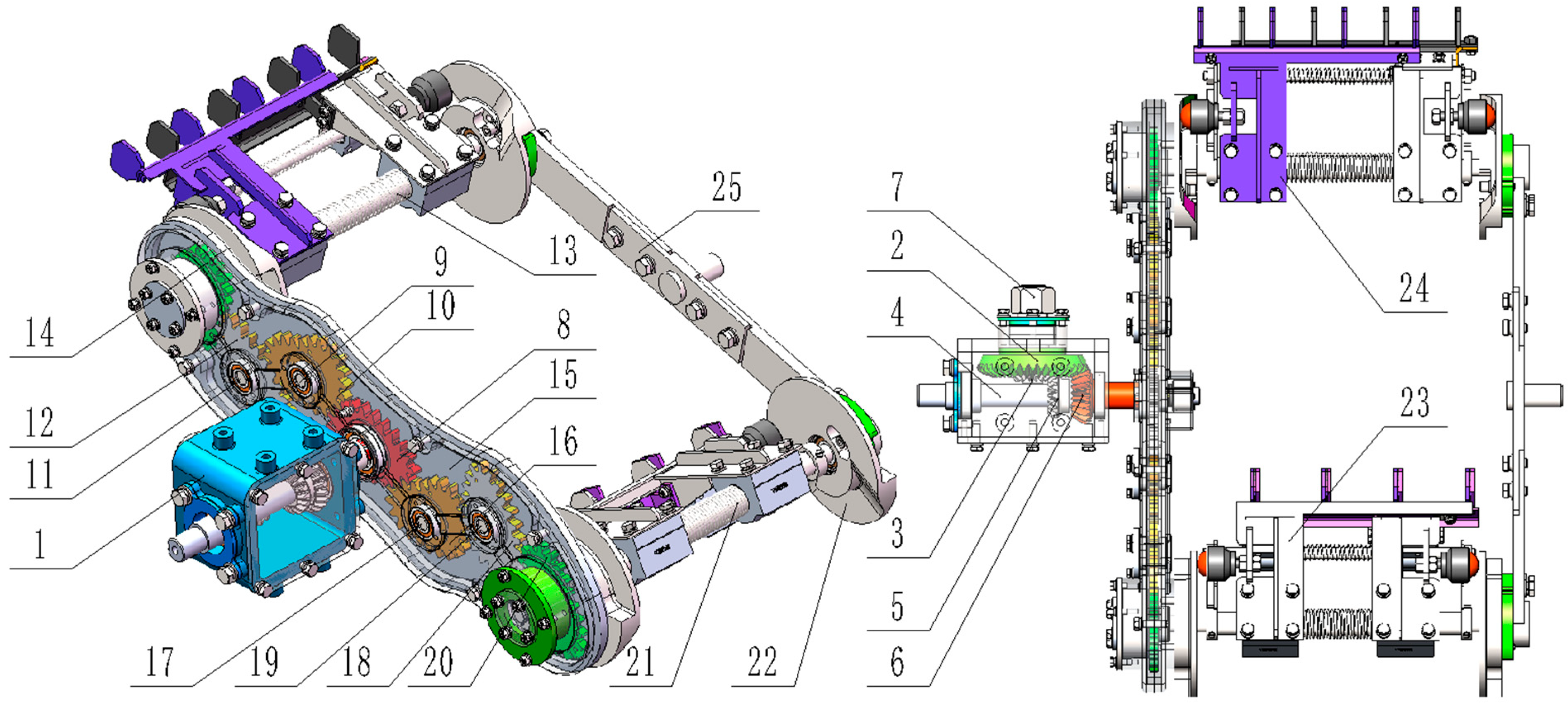
Figure 1. Structure diagram of seedling-picking mechanism. 1. Transmission box body; 2. upper-drive large bevel gear; 3. upper-drive small bevel gear; 4. power input shaft; 5. lower-drive bevel gear; 6. lower-drive large bevel gear; 7. upper bevel gear drive shaft; 8. sun gear; 9. intermediate shaft I; 10. intermediate gear I; 11. intermediate shaft II; 12. intermediate gear II; 13. upper planetary axis; 14. planetary gear I; 15. shell of gearbox; 16. intermediate gear III; 17. intermediate shaft III; 18. intermediate gear IV; 19. intermediate axle IV; 20. planetary gear II; 21. lower planetary axis; 22. end face cam; 23. lower seedling-picking end effector; 24. upper seedling-picking end effector; 25. to rotate the support secondary arm.
Agriculture 15 01563 g001
Figure 2. Structure diagram of the end effector for seedling-picking mechanism. 1. Planetary shaft; 2. left end face cam; 3. left universal ball bearing; 4. compression spring A; 5. compression spring B; 6. upper clamping seedling patch-fixing plate; 7. lower clamping seedling patch-fixing plate; 8. small slider guide shaft; 9. right universal ball bearing; 10. end face cam connecting disc; 11. right end face cam; 12. support arm; 13. small sliders; 14. large slider.
Agriculture 15 01563 g002
Figure 3. Mathematical model of the movement characteristics of the seedling-picking mechanism.
Agriculture 15 01563 g003
Figure 4. Relative motion trajectory diagram. 1. Motion trajectory; 2. seedling-picking mechanism; 3. pepper plug seedlings; 4. seedling box.
Agriculture 15 01563 g004
Figure 5. Main interface of optimization design software for stem-clamping-and-pulling-out picking mechanism. 1. Menu bar; 2. graphic display area; 3. parameter input area; 4. step adjustment area; 5. target area.
Agriculture 15 01563 g005
Figure 6. Summary analysis of the effect of different variables on the seedling-picking mechanism.
Agriculture 15 01563 g006
Figure 7. Comparison of relative motion trajectory.
Agriculture 15 01563 g007
Figure 8. Final assembly model of seedling-picking mechanism.
Agriculture 15 01563 g008
Figure 9. Simulation of the end effector for seedling picking.
Agriculture 15 01563 g009
Figure 10. Summary of cusp motion trajectory of seedling picking.
Agriculture 15 01563 g010
Figure 11. Posture of key positions of the seedling-picking mechanism.
Agriculture 15 01563 g011
Figure 12. Bench seedling-picking test.
Agriculture 15 01563 g012
Figure 13. Analysis chart of seedling-sampling test angle.
Agriculture 15 01563 g013
Table 1. Parameter optimization results.
Input ParameterParameter Value/mmInput ParameterParameter Value/°
r040θ130
r160θ260
r2120θ390
r340θ4120
r440θ5150
r540θ6180
r6100θ7210
r7120θ8240
r860θ9270
r980θ10300
r1060θ11330
S180Det−60
H180φH0284
YX434Yy97
Ya57ɑ1−50
H120ɑ260
Table 2. Summary of key angles for high-speed cameras.
The Clips Begin to CloseThe Clips Are Completely ClosedThe Clips Begin to OpenThe Clips Are Completely Open
337.41°336.26°286.26°285.12°
Table 3. Comparison of the angles of the seedling-picking mechanism.
Optimization SoftwareHigh-Speed Camera TestBench
Seedling-Picking Test
The clips start to close337.26°337.41°337.67°
The clips are completely closed336.14°336.26°336.59°
The clips start to open285.72°286.26°285.83°
The clips are completely open284.24°285.12°284.58°
Disclaimer/Publisher’s Note: The statements, opinions and data contained in all publications are solely those of the individual author(s) and contributor(s) and not of MDPI and/or the editor(s). MDPI and/or the editor(s) disclaim responsibility for any injury to people or property resulting from any ideas, methods, instructions or products referred to in the content.