Article

Design and Experiment of Autonomous Shield-Cutting End-Effector for Dual-Zone Maize Field Weeding

1
Beijing Institute of Technology, Beijing 100081, China
2
The State Key Laboratory of Multimodal Artificial Intelligence Systems, Institute of Automation, Chinese Academy of Sciences, Beijing 100190, China
*
Author to whom correspondence should be addressed.
Agriculture 2025, 15(14), 1549; https://doi.org/10.3390/agriculture15141549
Submission received: 18 June 2025 / Revised: 14 July 2025 / Accepted: 17 July 2025 / Published: 18 July 2025

Abstract

This study presented an autonomous shield-cutting end-effector for maize surrounding weeding (SEMSW), addressing the challenges of the low weed removal rate (WRR) and high seedling damage rate (SDR) in northern China’s 3–5 leaf stage maize. The SEMSW integrated seedling positioning, robotic arm control, and precision weeding functionalities: a seedling positioning sensor identified maize seedlings and weeds, guiding XYZ translational motions to align the robotic arm. The seedling-shielding anti-cutting mechanism (SAM) enclosed crop stems, while the contour-adaptive weeding mechanism (CWM) activated two-stage retractable blades (TRWBs) for inter/intra-row weeding operations. The following key design parameters were determined: 150 mm inner diameter for the seedling-shielding disc; 30 mm minimum inscribed-circle for retractable clamping units (RCUs); 40 mm ground clearance for SAM; 170 mm shielding height; and 100 mm minimum inscribed-circle diameter for the TRWB. Mathematical optimization defined the shape-following weeding cam (SWC) contour and TRWB dimensional chain. Kinematic/dynamic models were introduced alongside an adaptive sliding mode controller, ensuring lateral translation error convergence. A YOLOv8 model achieved 0.951 precision, 0.95 mAP50, and 0.819 mAP50-95, striking a balance between detection accuracy and localization precision. Field trials of the prototype showed 88.3% WRR and 2.2% SDR, meeting northern China’s agronomic standards.

1. Introduction

Weeds severely impact agricultural production as they compete with crops for essential resources such as light, water, and nutrients. This competition restricts crop growth, reduces yields, deteriorates quality, and decreases farmers’ incomes [1,2,3,4]. Maize, one of the world’s vital cereal crops, is especially prone to weed interference during its early growth stages, specifically the 3–5 leaf stage. When weeds are not promptly removed, maize may experience growth retardation and even yield decline [5]. Traditional weeding methods demand significant labor input and are inefficient, thus being unable to meet the precision management requirements of modern agriculture. Consequently, the development of maize weeding robots with precise weeding capabilities and low SDR is crucial. These robots should be adaptable to automated operations in narrow fields, reducing labor intensity, enhancing weeding efficiency, and facilitating the intelligent and precise development of agriculture [6,7].
Weed management in maize fields predominantly involves three techniques: mechanical, chemical, and laser weeding. Mechanical weeding, in contrast to chemical weeding, provides a greener alternative by decreasing herbicide application, thus mitigating environmental contamination. When compared with laser weeding, mechanical weeding demonstrates lower reliance on high-precision visual recognition systems, higher adaptability, and reduced energy consumption. Consequently, mechanical weeding was chosen as the operation mode for the maize weeding robot in this research.
The core challenge in designing maize weeding robots resides in the end-effector. Current research is primarily divided into two categories: contact-type and non-contact-type mechanisms. Contact-type weeding devices (contact with the soil surface) act directly on weed roots by penetrating the soil, yielding remarkable weeding results. A representative example is Lemken’s EC-weeder [8]. It utilizes the downward pressure of a compression spring to enable finger-clamp weeders to penetrate compacted soil and efficiently remove inter-row weeds. Liu et al. [9] developed a double-disc cultivator weeder that integrates disc-type weeding components with single- (double-) winged shovels, thereby improving operational quality. Chen et al. [10,11] developed an intra-row brush weeding manipulator, where a hydraulic motor rotates an eccentric cutter bar via gear transmission, enabling brush weeders to operate around crop plants. After parametric optimization, this system achieves 83.4% WRR with 2.5% SDR. To adapt to different plant-spacing, row-spacing, and growth stages, Gobor et al. [12] developed a horizontally rotating integrated arm weeding tool along crop rows. Comprising an arm holder and three or more integrated arms, the tool primarily detected the distance between adjacent plants and the angular position of the weeding mechanism.
Non-contact weeding mechanisms typically employ rotating blades or clamping and pulling devices to perform weeding operations while minimizing soil disturbance, reducing operational resistance, and alleviating crop roots damage. Nørremark et al. [13,14] developed a claw-type intra-row weeding robot equipped with four S-shaped vertical ground-penetrating tines for precise weed removal around plants. Pérez-Ruíz et al. [15] designed a pneumatic oscillating weeding device that avoids seedlings while weeding. Tested in precision-transplanted row crops, this design might also suit direct-seeded row crops. Chen et al. [16,17] developed a weeding robot applicable to the maize seedling stage. This robot integrates mechanical and chemical weeding approaches. It first cuts the weeds and then sprays herbicides to impede weed regrowth. Jia et al. [18] designed an intra-row weeding device for the maize-jointing stage. Once the mechanical flexible shaft detects maize seedlings, the weeding component drives the comb teeth to rotate intermittently, thus avoiding the plants. This device attains 94.7% WRR and 5.9% SDR.
Recent advances in machine vision have significantly enhanced precision weeding through innovative weed detection technologies, providing essential technical support for the mechanical weeding devices discussed in preceding sections. Early studies primarily focused on integrating color features with morphological analysis for plant recognition. Slaughter et al. [19,20] pioneered real-time color segmentation using dual-camera systems to monitor crop rows, achieving positioning accuracy ranging from 4.2 mm in weed-free conditions to 12 mm under high weed densities. To address species differentiation challenges, Pantazi et al. [21] introduced an active learning framework utilizing spectral reflectance differences, where Self-Organizing Maps and Mixture of Gaussians classifiers demonstrated 100% crop recognition accuracy with weed identification rates between 53% and 94%. Subsequent research leveraged deep learning for improved robustness, with Sa et al. [22] developing an encoder–decoder CNN architecture that processes multispectral aerial imagery through NDVI-based vegetation segmentation, enabling automated crop–weed distinction in complex field conditions. Simultaneously, Dyrmann et al. [23] overcame occlusion challenges in cereal fields through a fully convolutional neural network trained on 17,000 annotated field images, effectively detecting weeds despite overlapping foliage. In recent years, YOLO (You Only Look Once), a cutting-edge deep-learning object detection framework, has gained prominence in agricultural applications. Its unique architecture enables rapid and accurate real-time detection, making it well-suited for the dynamic and complex scenarios of precision agriculture. By integrating YOLO with existing technologies, such as spectral analysis, aerial imaging, and occlusion-handling algorithms, researchers have established a robust multimodal data fusion paradigm. This approach effectively meets the stringent demands of real-time operation and environmental adaptability in modern farming. The successful implementation of YOLO-based models in previous studies has laid a solid foundation for further optimizing weeding mechanisms, as demonstrated in the subsequent sections of this paper.
Existing studies have primarily focused on single-zone weeding (either inter-row or intra-row) in maize fields, resulting in suboptimal mechanical weeding performance. Additionally, insufficient precision in seedling–weed identification and motion control often leads to crop damage. Furthermore, there is a lack of innovative research on the theory and mechanism design for simultaneous inter-row and intra-row weeding. To address these limitations, this study proposes an SEMSW. First, the seedling positioning sensor localizes the positions of maize seedlings and weeds. The control system drives the weeding robotic arm to translate in the X, Y, and Z directions according to the feedback position coordinates, aligning the SEMSW with the maize seedlings. The SAM then encloses and protects the crop stems, while the CWM drives the TRWB through rotational shaping motions to cut weeds in both inter-row and intra-row areas.
The main research aims of this study are as follows. First, critical parameters for the SEMSW’s key components are determined through theoretical modeling. Second, by modeling the structure of the weeding robotic arm, its kinematic and dynamic models are established, and a lateral translation error model of the robotic arm is constructed. An adaptive sliding mode controller for the lateral translation mechanism is designed, and its stability is verified to ensure the convergence of lateral translation errors. Additionally, a high-performance weed detection model based on YOLOv8 is developed to enhance the SEMSW’s operational precision. Finally, prototype fabrication and field trials validate its operational efficacy, providing valuable references for maize weeding research in the agricultural systems of northern China.

2. Materials and Methods

2.1. Working Principle and Machine Structure

2.1.1. Working Principle

The SEMSW operational workflow consisted of two sequential phases: seedling-shielding and weeding. During the seedling-shielding phase, the seedling positioning sensor (16) in the SAM (1) first precisely located target maize seedlings. The end-effector subsequently descended vertically, synchronously lowering the anti-cutting rotating shield (9) of SAM (1) to envelop the identified seedlings. Finally, due to the close connection between the RCU (8), when the shielding drive motor (10) rotated counterclockwise, the anti-cutting rotating shield (9) was subjected to a counterclockwise rotational driving force. This force caused the sliding groove at the connection between the anti-cutting rotating shield (9) and the RCU (8) to rotate, pushing the RCU axle (12) to translate toward the center along the sliding groove on the seedling-shielding fixed disc (6). As a result, all RCUs (8) contract toward the center, completing the contraction movement to enclose and protect the maize plants, thus avoiding damage.
In the weeding phase, first, the transmission gearbox (4) converted torque from the weeding drive motor (35) into rotational motion of the drive rotary disk (27) on the CWM (2), energizing the TRWB (29) with cutting forces. Second, the stationary SWC (26) cooperated with the rotating disk (27), enabling the telescopic control axis (30) to move along the contour track set by the weeding blade limiting chute on the SWC (26), driving the TRWB (29) to perform contour-adaptive cutting motions. The high-speed rotating TRWB (29) simultaneously cleared weeds in both inter-row and intra-plant spaces surrounding the maize seedlings.
Upon completing weeding, the shielding drive motor (10) rotated clockwise to retract the RCUs (8), disengaging from the seedlings. The end-effector ascends until achieving full separation from the plants, completing one operational cycle of the SEMSW.

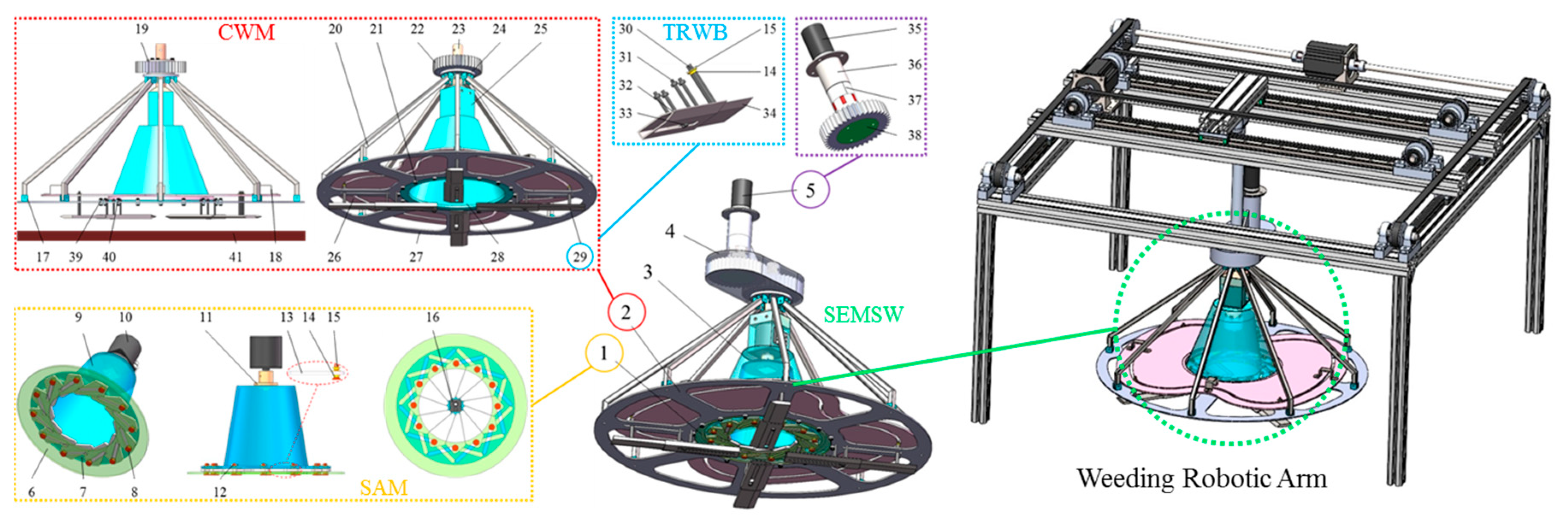
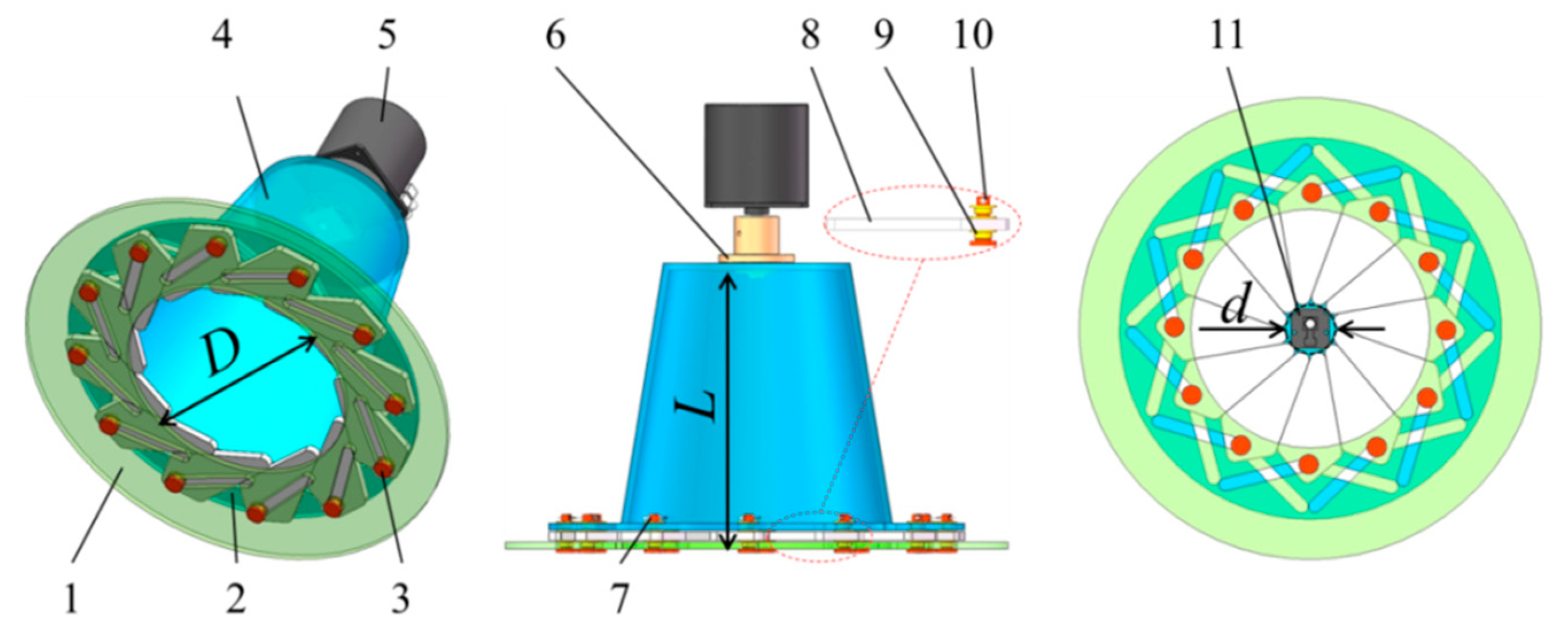
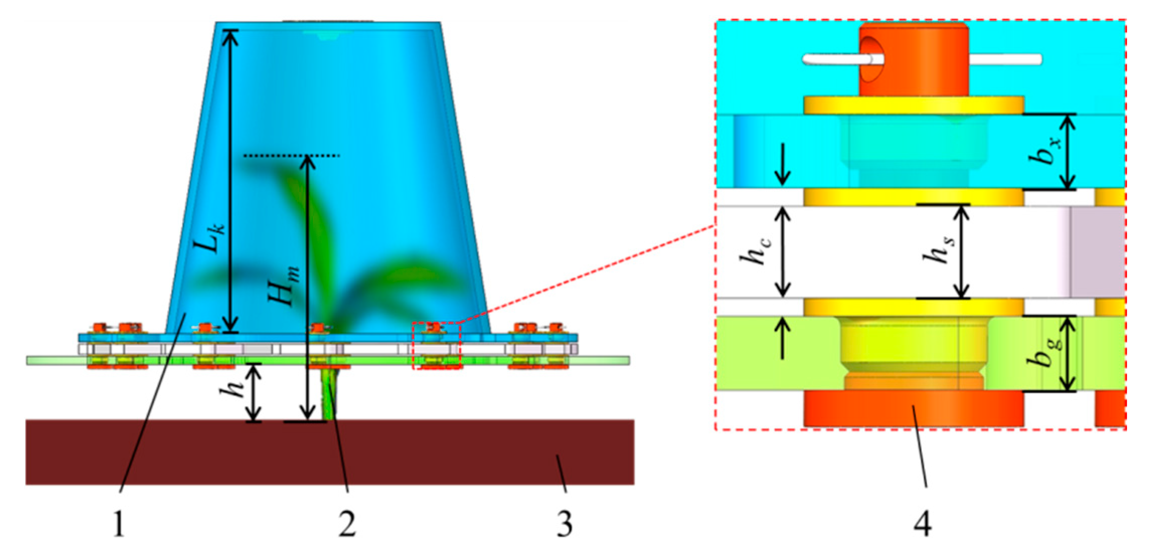
2.1.2. Structure of the SEMSW

The SEMSW was installed below the weeding robotic arm, composed of the SAM (1), the CWM (2), the end-effector bracket (3), the transmission gearbox (4), and the weeding drive mechanism (5). Its overall structure and installation location are shown in Figure 1. The SAM (1) was installed on the inner side of the end-effector bracket (3), while the CWM (2) was mounted on its outer side. The weeding drive mechanism (5) was connected to the CWM (2) through the transmission gearbox (4).

2.2. Adaptive Sliding Mode Control of Weeding Robotic Arm

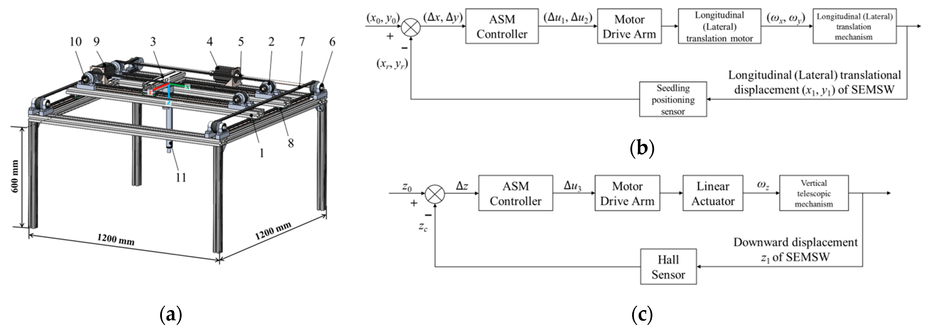
2.2.1. Control Process of Weeding Robotic Arm

The structure and control process of the weeding robotic arm are illustrated in Figure 2. The seedling positioning sensor first detected the location of maize seedlings and fed the position information back to the control system. Based on the sensor data, the control system calculated the motion path of the robotic arm and drove the longitudinal translation mechanism (1), lateral translation mechanism (2), and vertical telescopic mechanism (3) to work in coordination.
The longitudinal translation motor (4) drove the synchronous belt pulley (6) to rotate through the longitudinal motor-connecting shaft (5), driving the synchronous belt (7) to move. The synchronous belt (7) then drove the slide slider (8) and the longitudinal translation mechanism (1) to achieve longitudinal movement. The lateral translation motor (9) adopted a similar approach, driving the synchronous belt transmission mechanism through the lateral motor-connecting shaft (10) to enable the lateral translation mechanism (2) to complete lateral movement. The linear actuator (11) adjusted the vertical position of the robotic arm through telescopic actions and achieved precise control by integrating feedback signals from Hall sensors. Through the collaborative interaction of sensors, the control system, and mechanical structures, the robotic arm could achieve precise positioning in three degrees of freedom (longitudinal, lateral, and vertical), effectively meeting the requirements of weeding operations.

2.2.2. Derivation of Kinematic and Dynamic Models

From the motion principle of the robotic arm, the linear movement of the lateral and longitudinal translation mechanisms was driven by the rotation of the motor shaft, while the telescopic motion of the vertical telescopic mechanism was realized by the linear actuator motor driving the ball screw to rotate. Neglecting the speed loss caused by friction during motion, according to the kinematic equation v = ωr, the linear velocity of the translation (telescopic) mechanism was equal to the product of the angular velocity of the motor shaft and the distance between them. This converted the differential form of the translation mechanism’s displacement into the angular velocity of the motor shaft, thereby constructing the kinematic equation of the weeding robotic arm:
d d t x 1 ( t ) y 1 ( t ) z 1 ( t ) = ω x ( t ) r w ω y ( t ) r w i ω z ( t ) l s / 2 π , t 0 , t f
where x1, y1, and z1 represent the coordinates of the weeding robotic arm in the spatial coordinate system (Figure 2a), m; ωx, ωy, and ωz denote the output angular velocities of the lateral translation motor, longitudinal translation motor, and linear actuator motor, rad/s; rw is the radius of the synchronous pulley, m; i is the synchronous transmission ratio between the linear actuator motor and the screw; ls is the lead of the screw, m; and tf is the time required for the weeding robotic arm to move and align with the target point of the maize seedling (a non-fixed value), s.
As shown in Figure 3, the lateral translation motor provides a driving torque Mxa for the lateral translation mechanism. During the process of driving the lateral translation mechanism to achieve lateral movement, the motor transmitted power to the synchronous belt through the synchronous belt pulley, which was a first-level mechanical transmission with a transmission efficiency η1 of 98%. Additionally, the lateral translation of the lateral unit needed to overcome the frictional resistance fxa generated when the slider slides on the slide rail.
The driving principle of the longitudinal translation mechanism was similar to the lateral translation mechanism and was not repeated here. Since the linear actuator was directly connected to the SEMSW, energy loss can be ignored. Based on the above analysis and combining with the kinematic Equation (1) of the robotic arm, the dynamic equation is constructed as follows:
d d t J 1 ω x ( t ) J 2 ω y ( t ) J 3 ω z ( t ) = M x a η 1 f x a r x a M y a η 1 f y a r y a T z a / i , t 0 , t f
where J1, J2, and J3 represent the moments of inertia of the lateral translation mechanism, longitudinal translation mechanism, and vertical telescopic mechanism during motion, respectively, kg·m2; Mxa is the driving torque provided by the lateral translation motor, N·m; fxa is the sliding friction force experienced by the mechanism during lateral translation, N; rxa is the force arm length of the sliding friction force fxa, m; Mya is the driving torque provided by the longitudinal translation motor, N·m; fya is the sliding friction force experienced by the mechanism during longitudinal translation, N; rya is the force arm length of the sliding friction force fya, m; and Tza is the torque of the linear actuator, N·m.

2.2.3. Problem Formulation

Agricultural robotic arm control systems encountered multiple challenges in practical field applications. The structural complexity of agricultural machinery, variability of farmland operational environments, and inherent system uncertainties collectively limited the grasping and alignment performance of robotic manipulators. Due to the strong coupling effects and significant nonlinear uncertainties in Equation (2), direct implementation of adaptive sliding mode control was difficult. Thus, an equivalent model transformation of System (2) was required to simplify the controller design. Through parameter substitution θ1 = J1 and the definition of new state variables x2 = ωx(trw, with control input u1 = Mxa·η1/rw and disturbance term Δ1 = −fxa·rxa/rw, System (2) can be reconstructed into the following state-space representation:
x ˙ 1 = x 2 θ 1 x ˙ 2 = u 1 + Δ 1
where J1 denotes the unknown rotational inertia of the lateral translation system, which constitutes a positive constant. The disturbance term Δ1 represents the aggregate uncertainty encompassing external disturbances and unmodeled dynamics.
Assumption 1:
The upper and lower bounds of the uncertain parameter θ1 are defined as:
θ 1 Ω { θ 1 : 0 < θ min θ 1 θ max }
Assumption 2:
The disturbance term Δ1 is bounded, expressed as:
Δ 1 D

2.3. Dataset and Weed Detection

2.3.1. Dataset

The dataset was obtained from https://github.com/zhangchuanyin/weed-datasets (accessed on 1 May 2025), a publicly accessible resource [24] available for download. Comprising 1390 training, 595 validation, and 523 test images of maize and weeds, it closely resembled field images captured during real-world experiments with the weeding device. The dataset included plant images under diverse lighting (day/night) and soil conditions. Representative samples are shown in Figure 4.
To meet the requirements for subsequent image detection model training, this paper annotated the dataset using LabelMe, a widely adopted tool in image detection tasks. The annotation process ensures precise detection of targets within the images.

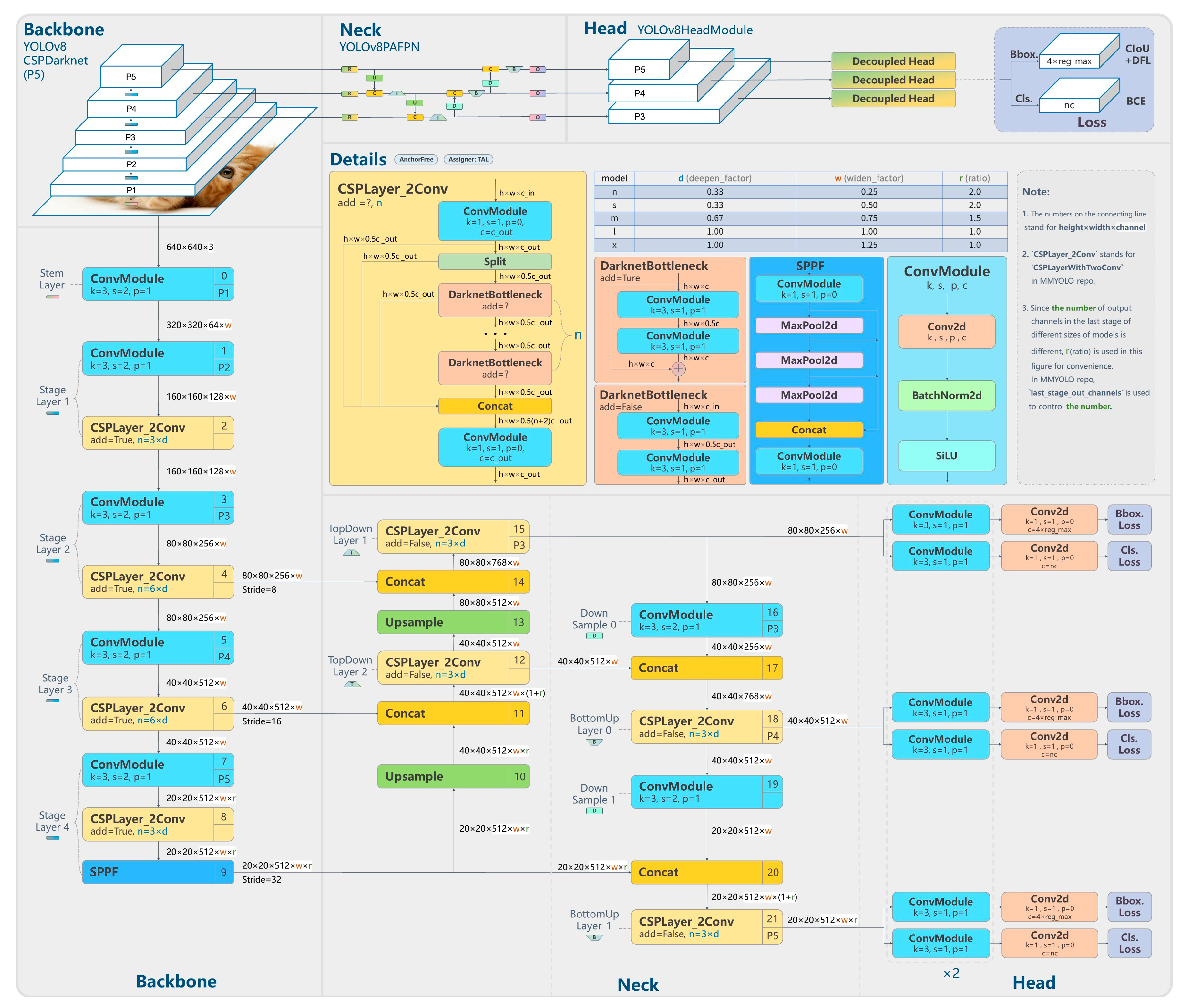
2.3.2. Weed Detection

Considering its validated performance in similar vegetation detection tasks, compatibility with system computational limits, and field applicability, YOLOv8 [25] was adopted to develop a robust weed recognition model for the SEMSW. As shown in Figure 5, this advanced single-stage detector features an optimized Cross-Stage Partial (CSP) backbone and modified Path Aggregation Network (PANet) for efficient multi-scale feature extraction. Its anchor-free architecture with decoupled classification/regression branches balances detection accuracy and real-time performance, making it suitable for on-board agricultural machinery deployment.

3. Results and Discussion

3.1. Parametric Design of SAM

The SAM effectively protected maize seedlings by preventing collision damage to cotyledons and stalks during operation. Through parameter and structural optimization, the end-effector’s stability during seedling-shielding was enhanced, while rigid contact between the shield and seedlings was avoided to reduce breakage risks.
Therefore, this study conducted structural and parametric designs of the SAM based on the actual maize cultivation conditions in northern China (Figure 6 and Figure 7).

3.1.1. Inner Diameter D of the Seedling-Shielding Disc

The seedling-shielding fixed disc must maintain sufficient inner aperture. During downward SAM operation for seedling envelopment, rigid contact between maize cotyledons and the disc should be avoided. Cotyledons should either smoothly enter the disc’s aperture or transition into the anti-cutting rotating shield without physical interaction, thereby preventing seedling injury, breakage, or soil-surface compression of cotyledons.
The inner diameter D requires precise calibration. Excessive D increased the structural footprint of the CWM, elevating collision risks with adjacent seedlings. Thus, D was optimized to the minimum value, ensuring reliable seedling envelopment. Field measurements of 100 groups of maize seedlings at the 3–5 leaf stages revealed that the maximum cotyledon spans were 8~15 cm. Hence, the finalized D was set as 150 mm.

3.1.2. Minimum Inscribed-Circle Diameter d of the RCUs

During counterclockwise rotation of the anti-cutting rotary disc, the RCUs progressively contracts toward the center of the seedling-shielding fixed disc, as shown in Figure 6. At its maximum contraction position, the minimum inscribed-circle diameter formed by the tops of the RCUs components was defined as d.
Parametric design requires that d slightly exceeds the maize stem diameters to prevent clamping-induced injury. Through measurement and statistics, the diameter dm of the majority of the maize stalks was found to be 1.5~2.5 cm. Consequently, d was optimized to 30 mm to ensure safe stem clearance while maintaining mechanical reliability.

3.1.3. Ground Clearance h of the SAM

Field-surface irregularities necessitated avoiding direct contact between the end-effector and the ground to minimize soil disturbance, reduce operational resistance, and ensure weeding efficacy. However, excessive ground clearance would prevent the SAM from effectively surrounding and protecting maize plants. As shown in Figure 7, the SAM typically envelops the cotyledon part of the maize plants, and exposing the bottom part of the stalk meets the operation requirements. Based on these constraints, the ground clearance h of the SAM was designed to be 40 mm.

3.1.4. Seedling-Shielding Height L

The seedling-shielding height L pertained to the required height for the SAM to cover maize seedlings from top to bottom through the inner hole of the seedling-shielding fixed disc under the natural growth posture of the maize seedlings. As shown in Figure 6 and Figure 7, with the premise of ensuring a sufficient height h from the ground, it was necessary to ensure that the top inside the anti-cutting rotating shield did not come into contact with the maize seedlings to prevent bruising or breaking. The calculation equation for the seedling-shielding height L was as follows:
L = L k + b x + b g + h s + 2 h c L > L k > H m h
where L is the seedling-shielding height, mm; Lk is the height of the anti-cutting rotating shield, mm; bx is the thickness of the anti-cutting rotating disc, which is taken as 4 mm; bg is the thickness of the seedling-shielding fixed disc, which is taken as 4 mm; hs is the height of the RCU, which is taken as 5 mm; hc is the gap between RCUs and disc, which is taken as 1 mm; Hm is the maximum height of maize at the 3–5 leaf stage, mm; and h is the height of the SAM from the ground, mm.
To ensure that the anti-cutting rotating shield did not come into contact with maize seedlings, its height had to be greater than the difference between the maximum height Hm of maize seedlings and the height h of the SAM from the ground. Through field measurements, the height range of maize seedlings in the 3–5 leaf stage was found to be 12–19 cm. The maximum height Hm of maize in this stage was set as 190 mm. According to the previous analysis, the height h of the SAM from the ground was 40 mm. Thus, from Equation (6), Lk > Hmh = 150 mm. To meet this condition, the height Lk of the anti-cutting rotating shield was designed to be 155 mm. Finally, by substituting Lk and the other parameter values into Equation (6) again, the seedling-shielding height L was designed to be 170 mm.

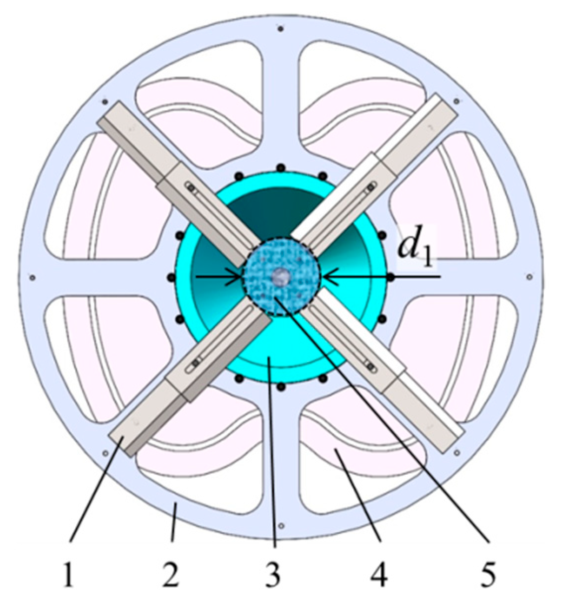
3.2. Parametric Design of CWM

The core design challenges for the CWM involve two critical components: the contour curve design of the SWC and the dimensional chain design of the TRWB. As depicted in Figure 8, the schematic clarifies the CWM’s key geometric parameter and its spatial configuration, specifically highlighting the minimum inscribed-circle diameter d1 of the TRWB.

3.2.1. Minimum Inscribed-Circle Diameter d1 of the TRWB

As shown in Figure 9, the minimum inscribed-circle diameter d1 of the TRWB refers to the diameter of the non-cutting central zone formed by the TRWB during counterclockwise rotation. This parameter had to balance seedling protection and weeding efficacy. If d1 was excessively small, the TRWB risked contacting the protected maize seedlings at the inner fixed ring of the fixed weeding blades. Conversely, if d1 was overly large, the non-cutting areas increased, thus elevating the likelihood of incomplete weed removal near the seedlings.
Field measurements indicated that the diameter range of the maize seedling stalks dm was 1.5~2.5 cm. Therefore, the minimum inscribed-circle diameter d1 of the TRWB should not have been less than 25 mm. Meanwhile, considering the diversity of plant morphologies, seedling-enclosing postures, and the uncertainties of the operating environment such as mechanical vibrations and sensor-positioning errors, a safety factor K = 4 was adopted. The minimum inscribed-circle diameter d1 of the TRWB was designed to be 100 mm to minimize the risk of bruising the seedlings as much as possible.

3.2.2. Contour Curve Design of the SWC

The significant variability in maize row and plant-spacing constituted one of the primary technical challenges for simultaneous inter-row and intra-row weeding [26]. In northern China, conventional agronomic practices dictated maize planting with a row-spacing of 55–60 cm and plant-spacing of 22–27 cm [27,28,29]. Figure 10a illustrates the theoretical planting model under these parameters. Specifically, when ensuring that the TRWB do not touch the surrounding eight maize plants, the orange-shaded area in Figure 10b represents the minimum cutting area required for weeding through a rotational cutting method.
Conventional rotary cutters struggled to match rectangular working areas due to their circular motion trajectories. In this study, a planar disc cam mechanism was innovatively employed. A customized contour curve guided the cutter to generate a quasi-rectangular motion path. The maximum row-spacing value (Ls = 60 cm) and the minimum plant-spacing value (Ps = 22 cm) were selected as reference values for the design of the SWC. As shown in Figure 11b, the boundary points A-H of the minimum cutting area are identified as key trajectory points.
As shown in Figure 11a, the cam contour was composed of eight segments of composite curves, and ⊙BYFX was the base circle of the cam. First, to prevent the weeding blade from touching adjacent maize seedlings between plants, it was essential to ensure that the length of OB’ was less than the difference between the plant-spacing Ps and the radius rm of the maize stalk. The base-circle radius rb of the cam was designed to be 217.5 mm, and the cam height B’F’ was 435 mm. Second, to ensure that the weeding blade could cover in the row-spacing direction, the width H’D’ of the cam should not be less than the minimum theoretical cutting width HD. The width H’D’ of the cam was designed to be 600 mm. Finally, the diagonal A’E’ of the cam should not be less than the length of the diagonal of the rectangle formed by the maize sowing row-spacing and plant-spacing. The length zb of the diagonal A’E’ of the cam was designed to be 660 mm. The above-mentioned calculation methods are shown in Equation (7).
O B ¯ = O F ¯ = O X ¯ = O Y ¯ = 1 2 B F ¯ = 1 2 X Y ¯ < P s r m O D ¯ = O H ¯ = 1 2 H D ¯ 1 2 L s O A ¯ = O C ¯ = O E ¯ = O G ¯ = 1 2 A E ¯ = 1 2 C G ¯ 1 2 P s 2 + L s 2
where Ps is the plant-spacing of maize sowing, cm; rm is the radius of the maize stalk, cm; Ls is the row-spacing of maize sowing, cm; and the remaining alphabetic symbols denote the specified points and their connecting lines in Figure 11.
As depicted in Figure 11b,c, the cam trajectory efficiently covers the minimum theoretical cutting area while avoiding contact with adjacent maize plants. To mitigate rigid impact, the contour curve was designed with continuous gradient arcs. Simulation results demonstrated that this approach would increase the coverage rate of the SWC from 69.3% to 98.5%. The minor uncut regions caused by the continuity of arcs A’G’ and arcs C’E’ will be resolved in subsequent research through a telescopic compensation mechanism integrated into the TRWB.

3.2.3. Dimensional Chain Design of the TRWB

To ensure precise retraction and extension of the TRWB at critical positions, it was necessary to design their dimensional chain, as shown in Figure 12. The key parameters included: the minimum retraction distance W1 of the TRWB, the maximum extension distance W2 of the TRWB, the length l1 of the fixed blade body, and the length l2 of the telescopic blade body.
First, to guarantee structural rigidity and strength, the lengths of the fixed blade body and the telescopic blade body should have been comparable. Referring to the Mechanical Design Handbook [30], both lengths were recommended to be set as half of W2. To optimize telescopic performance, the telescopic blade body was slightly longer than the fixed blade body, satisfying the relationship:
l 2 = l 1 + q 3
where l1 is the length of the fixed blade body, mm; l2 is the length of the telescopic blade body, mm; and q3 represent the unknown lengths in Figure 12b, mm.
Second, when designing the dimensional chain of the TRWB, it was also necessary to consider its motion states at different positions. When the weeding blade rotated to the OB’ or OF’ position, it had to be ensured that it could contract to the minimum length W1. At this time, the tip of the telescopic blade body should be within the base circle B’YF’X (as shown in Figure 11a). When it rotated to the OA, OC, OE, or OG position, it had to be ensured that it could stretch to the maximum length W2. At this moment, the tip of the telescopic blade body should be outside the cam contour curve (as shown in Figure 11b). This was to ensure that the TRWB had a sufficient telescopic range to prevent missed cutting. As can be seen from Figure 12b, the dimensional chain equations are expressed as follows:
O B ¯ = 1 / 2 d 1 + p 1 + p 2 + q 3 < P s r m O A ¯ = 1 / 2 d 1 + p 1 + 2 p 2 + q 2 + q 3 1 / 2 P s 2 + L s 2 W 1 = p 1 + p 2 + q 3 < r b 1 / 2 d 1 W 2 = p 1 + 2 p 2 + q 2 + q 3 > z b 1 / 2 d 1 l 1 = p 1 + p 2   l 2 = 2 p 2 + q 1 + q 2 + q 3
where l1 is the length of the fixed blade body, mm; l2 is the length of the telescopic blade body, mm; W1 is the minimum contraction distance of the TRWB (W1 = l2) in mm; W2 is the maximum stretching distance of the TRWB, mm; d1 is the minimum inscribed-circle diameter of the TRWB, mm; p1, p2, q1, q2, q3 represent the unknown lengths in Figure 12b; and the design q3 = q1 = 5 mm. Ps is the plant-spacing of maize sowing, cm; rm is the radius of the maize stalk, cm; and Ls is the row-spacing of maize sowing, cm.
During the design process of the dimensional chain for the TRWB, the parameter values of the cam contour curve also needed to be considered. Incorporating the aforesaid design content, by substituting the parameters into Equation (9), it could be deduced that the minimum contraction distance W1 of the TRWB should be less than 167.5 mm. Consequently, W1 was designed as 165 mm. Similarly, it could be inferred that the maximum stretching distance W2 of the TRWB should be greater than 280 mm. Therefore, W2 was designed as 285 mm.
Upon substituting W1 = 165 mm and W2 = 285 mm into Equation (9) and performing the calculations, p1 was calculated as 125 mm, p2 as 35 mm, and q2 as 85 mm. Eventually, the length l1 of the fixed blade body was determined to be 160 mm, and the length l2 of the telescopic blade body was 165 mm. Such parameter design satisfied the requirements of the dimensional chain design and also guaranteed the mechanical performance of the TRWB.

3.3. Design of Adaptive Sliding Mode Controller

Given the fundamental similarity in control principles between lateral and longitudinal translation mechanisms, this study focused specifically on deriving the adaptive sliding mode equation for the lateral translation mechanism. The developed control methodology [31,32] maintained theoretical consistency with the longitudinal translation mechanism’s control framework. The sliding surface equation for the lateral positioning mechanism’s adaptive sliding mode controller is designed as follows:
s 1 = e ˙ + ρ e = x 2 x ˙ d + ρ e
where xd is the position command issued by the lateral translation motor, e = x1xd is the lateral position tracking error, and ρ > 0. Then:
s ˙ 1 = x ˙ 2 x ¨ d + ρ e ˙ θ 1 s ˙ 1 = θ 1 ( x ˙ 2 x ¨ d + ρ e ˙ )
Taking θ ^ 1 as the estimated value of θ1, the Lyapunov function is defined as:
V 1 = 1 2 θ 1 s 1 2 + 1 2 ζ θ ˜ 1
where θ ˜ 1 = θ ^ 1 θ1, and ζ > 0. Then:
V ˙ 1 = θ 1 s 1 s ˙ 1 + 1 ζ θ ˜ 1 θ ˜ ˙ 1 = s 1 ( θ 1 x ˙ 2 θ 1 x ¨ d + θ 1 ρ e ˙ ) + 1 ζ θ ˜ 1 θ ˜ ˙ 1           = s 1 ( u 1 + Δ 1 θ 1 ( x ¨ d + ρ e ˙ ) ) + 1 ζ θ ˜ 1 θ ˜ ˙ 1
The control law u1 is designed as:
u 1 = θ 1 ( x ¨ d ρ e ˙ ) k s s η sign ( s 1 )
where ks > 0 and η > D. Combining Equations (13) and (14) gives:
V ˙ 1 = s 1 ( θ 1 ( x ¨ d ρ e ˙ ) k s s 1 η sign ( s 1 ) + Δ 1 θ 1 ( x ¨ d ρ e ˙ ) ) + 1 ζ θ ˜ 1 θ ^ ˙ 1       = s 1 ( ( θ 1 θ 1 ) ( x ¨ d ρ e ˙ ) k s s 1 η sign ( s 1 ) + Δ 1 ) + 1 ζ θ ˜ 1 θ ^ ˙ 1       = s 1 ( ( θ ˜ 1 ( x ¨ d ρ e ˙ ) k s s 1 η sign ( s 1 ) + Δ 1 ) + 1 ζ θ ˜ 1 θ ^ ˙ 1       = k s s 1 2 η s 1 + Δ 1 s 1 + θ ˜ 1 ( s 1 ( x ¨ d ρ e ˙ ) + 1 ζ θ ^ ˙ 1 )
The adaptive law is taken as:
θ ^ ˙ 1 = ζ s 1 ( x ¨ d ρ e ˙ )
Then:
V ˙ 1 = k s s 1 2 η s 1 + Δ 1 s 1 k s s 1 2 0
Since V ˙ 1 = 0 if and only if s1 = 0, that was, when V ˙ 1 ≡ 0, s1 ≡ 0. According to LaSalle’s invariance principle [33], the closed-loop system was asymptotically stable, meaning that tf → 0, s1 → 0, proving the stability of the adaptive sliding mode controller.

3.4. Crop Detection Test

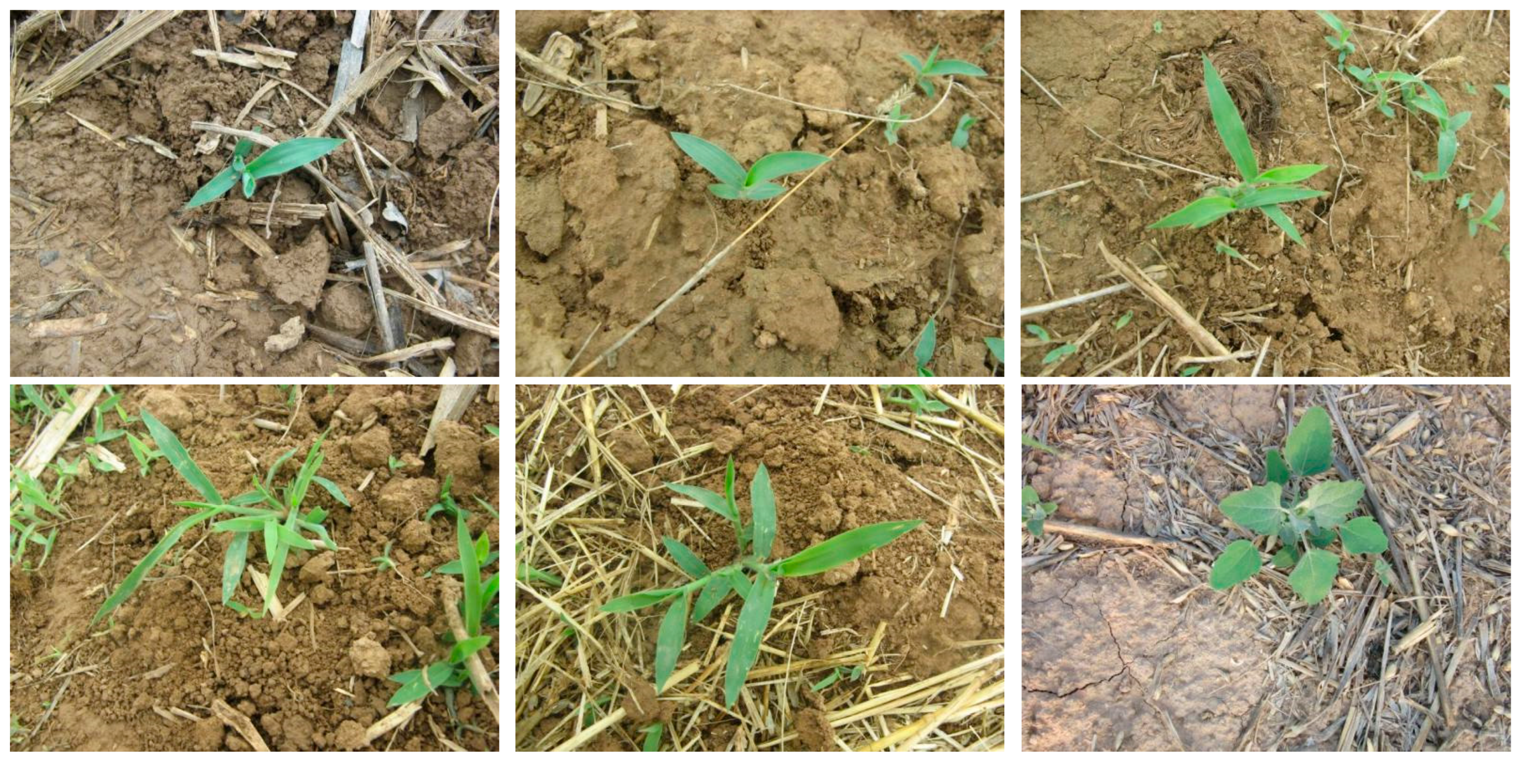
3.4.1. Maize Seedling Image Segmentation

The host computer performs image segmentation on all maize seedlings detected within the field of view of the seedling positioning sensor, as shown in Figure 13. It prioritized the maize seedling closest to the SEMSW for weeding operations. The host computer was equipped with an NVIDIA GeForce RTX 4090D GPU, and each image segmentation process takes approximately 1 s.

3.4.2. Environment of Weed Detection

The detection model was trained using the dataset described in Section 2.3. The training was conducted on a system with an NVIDIA GeForce RTX 4060 GPU, an Intel Core i5-12600KF CPU (3.70 GHz), 32 GB of RAM, and the Linux Ubuntu 20.04 operating system; the implementation was carried out in Python (v. 3.10) with the PyTorch (v. 2.4.1) library. The dataset was partitioned into training/validation/testing sets at a 0.7:0.2:0.1 ratio. The model underwent 50 epochs of training with a batch size of 16 and an input image size of 640 × 640.

3.4.3. Result of Weed Detection

As shown in Figure 14, the model’s inference accuracy improved consistently with increasing training epochs, indicating effective learning convergence. The detection results are summarized in Table 1, including:
The model demonstrates exceptional detection performance across various weed species in maize fields, as shown in Figure 15. Experimental results show the model achieved a precision of 0.951, including mAP50 of 0.95 and mAP50-95 of 0.819. These results demonstrated the model’s balance between detection accuracy and precise localization capability, critical for robotic weeding applications. This enabled the SEMSW to accurately identify different weed species, prevent crop misclassification, and minimize crop damage. Consistent performance across weeds with distinct morphological characteristics validated the model’s generalization capability under real-field conditions [34].

3.5. Field Validation Test

3.5.1. Test Conditions

The experiment was conducted on 24 April 2025 in the experimental field of the Chinese Academy of Agricultural Sciences (39°57′23″ N, 116°19′25″ E). The field, located at 39 m altitude with an atmospheric pressure of 1024.6 hPa, had a silt loam soil type. The maize variety employed was Baitiannuo 708, and the experimental subjects were 18-day-old maize seedlings (post-sowing) and the accompanying weed communities. During the experiment, the daily average temperature ranged from 7 °C to 23 °C, and there was no precipitation.
The experimental field was left fallow for one year, and artificial tillage and land preparation operations were carried out prior to maize sowing. To ensure the survival rate of maize, 4–5 maize seeds were sown per hole. Since all weeds were removed before sowing, there were relatively few weeds on the day of the experiment. As shown in Figure 16a, the weed density was 20–50 plants/m2, and the main weed species included Setaria viridis, mint (Mentha sp.), and Calystegia hederacea, etc. The actual row-spacing Ls in the experimental field was 60 cm, and the plant-spacing Ps was 27 cm. The environmental parameters of the experimental field are presented in detail in Table 2.

3.5.2. Test Method and Results

As shown in Figure 16b, the bench platform equipped with the SEMSW was used to conduct weeding performance tests in the experimental field. Since the bench platform lacked autonomous mobility, technicians manually lifted and positioned it above maize seedlings to align with the target plants. The WRR and SDR were adopted as evaluation indices.
Specifically, WRR was defined as the ratio of the number of effectively removed weeds after the bench platform’s operation to the total number of weeds before operation. Using a random sampling method, five maize seedling areas were randomly selected in the field for weeding tests. The effective weed counts within the end-effector’s coverage area were manually recorded before and after each test. For SDR, it was calculated as the percentage of bruised maize seedlings in the total number of seedlings. Given that visual assessment of seedling damage caused by weeding blades was sometimes challenging, this experiment defined seedling injury [18] as any contact between the TRWB and maize seedlings. After testing the weeding effect on all maize seedlings, the number of injured seedlings was counted to determine SDR. The detailed calculation methods for WRR and SDR are as follows:
λ 1 = F z F s F z × 100 % λ 2 = E s E z × 100 %
where λ1 is the WRR, %; λ2 is the SDR, %; Fz is the number of weeds before operation; Fs is the number of weeds remaining after operation; Ez is the total number of maize seedlings before operation; and Es is the number of damaged maize seedlings after operation.
Experimental results, as shown in Table 3, demonstrate that the SEMSW achieves simultaneous inter-row and intra-plant weeding, attaining a WRR of 88.3%. The weeding effect is illustrated in Figure 17. The SAM effectively reduced mechanical damage, with two collisions occurring among 91 maize seedlings, yielding an SDR of 2.2%.
Compared with the 3ZS-2 inter-row cultivation weeder developed by Liu et al. [9] (with an 85% WRR), the SEMSW increased the WRR by 3.9%. In comparison to Chen et al.’s [11] Intra-row Brush Weeding Manipulator, which achieved an 83.4% WRR and 2.5% SDR, the SEMSW improved the WRR by 5.9% while reducing the SDR by 12%. Relative to Jia et al.’s [25] seedling-avoiding weeding control device (5.9% SDR), the SEMSW lowered the SDR by 62.7%. Additionally, compared with the strictest industry benchmark for SDR (3%), the SEMSW reduced the rate by 23.3%, confirming the SAM’s superior performance in preventing seedling damage.
These performance metrics confirm that the developed weeding device significantly enhances crop protection while ensuring effective weed control, thus fulfilling the agronomic requirements for maize weeding in northern China.

4. Conclusions

This study proposed a novel shield-cutting end-effector for maize surrounding weeding (SEMSW) that integrated seedling positioning, robotic arm control, and precision weeding functions. The system first localized maize seedlings and weeds via a seedling positioning sensor, then drove the weeding robotic arm to perform XYZ translational motions for precise alignment with the seedlings. The seedling-shielding anti-cutting mechanism (SAM) enclosed crop stems for protection, while the contour-adaptive weeding mechanism (CWM) activated rotational motions of the two-stage retractable weeding blade (TRWB) to remove inter-row and intra-row weeds. Mathematical models were established to determine critical parameters, including the following: the inner diameter D of the seedling-shielding disc was 150 mm; the minimum inscribed-circle diameter d of the RCUs was 30 mm; the ground clearance h of the SAM was 40 mm; the seedling-shielding height L was 170 mm; and the minimum inscribed-circle diameter d1 of the TRWB was 100 mm. Additionally, the structure and parameters of the contour curve of the SWC and the dimensional chain of the TRWB were designed. Kinematic/dynamic models of the robotic arm were developed, alongside an adaptive sliding mode controller that ensured lateral translation error convergence. A YOLOv8-based weed detection model achieved 0.951 precision, 0.95 mAP50, and 0.819 mAP50-95, striking a balance between detection accuracy and localization precision for robotic weeding. Field tests of the prototype showed an 88.3% weed removal rate (WRR) and a 2.2% seedling damage rate (SDR), meeting the agronomic requirements for maize weeding in northern China.
Future work will optimize the mechanical structure and parameters of SEMSW using EDEM and ANSYS, validate the convergence/stability/robustness of the adaptive sliding mode controller via simulation, and deploy the YOLO algorithm on the weeding robot prototype for field trials to enhance practical applicability.

Author Contributions

Conceptualization, Y.L. (Yunxiang Li) and J.Y.; methodology, Y.L. (Yunxiang Li) and Y.Q.; software, Y.L. (Yunxiang Li) and Y.F.; validation, Y.L. (Yunxiang Li), Y.Q. and J.Y.; writing—original draft preparation, Y.L. (Yunxiang Li); writing—review and editing, Y.L. (Yunxiang Li), Y.Q., J.Y. and Y.L. (Yanfeng Lu); funding acquisition, Y.L. (Yanfeng Lu). All authors have read and agreed to the published version of the manuscript.

Funding

This study is supported by the Strategic Priority Research Program of the Chinese Academy of Sciences under (Grants XDA0450200, XDA0450202), and the Open Projects Program of State Key Laboratory of Multimodal Artificial Intelligence Systems.

Data Availability Statement

The dataset presented in this study are openly available in the weed datasets of Zhangchuanyin (Figure 4), available online at https://github.com/zhangchuanyin/weed-datasets (accessed on 1 May 2025), reference number [28]. The overview of the YOLOv8 structure (Figure 5) is available online: https://github.com/open-mmlab/mmyolo/blob/dev/configs/yolov8/README.md (accessed on 1 May 2025).

Acknowledgments

The authors sincerely thank Wenxia Wu for her valuable assistance with the prototype fabrication and field experiment implementation.

Conflicts of Interest

The authors declare no conflicts of interest.

Nomenclature

WRR/λ1Weed removal rate (%)DInner diameter of the seedling-shielding disc (mm)
SDR/λ2Seedling damage rate (%)dMinimum inscribed-circle diameter of the RCUs (mm)
SEMSWShield-cutting end-effector for maize surrounding weedingd1Minimum inscribed-circle diameter of the TRWB (mm)
SAMSeedling-shielding anti-cutting mechanismx1, y1, z1Coordinates of the weeding robotic arm in the spatial coordinate system
CWMContour-adaptive weeding mechanismiSynchronous transmission ratio between the linear actuator motor and the screw
TRWBTwo-stage retractable weeding bladeLkHeight of the anti-cutting rotating shield (mm)
RCURetractable clamping unitl1Length of the fixed blade body (mm)
SWCShape-following weeding caml2Length of the telescopic blade body (mm)
YOLOv8You only look once, version 8W1Minimum contraction distance of the TRWB (mm)
CSPCross-stage partialW2Maximum stretching distance of the TRWB (mm)
PANetPath aggregation networkFzNumber of weeds before operation
LSeedling-shielding height (mm)FsNumber of weeds remaining after operation
rmRadius of the maize stalk (cm)EzTotal number of maize seedlings before operation
dmDiameter of majority maize stalks (mm)EsNumber of damaged maize seedlings after operation
hGround clearance of the SAM (mm)ωxAngular velocities of the lateral translation motor (rad/s)
hcGap between RCUs and disc (mm)ωyAngular velocities of longitudinal translation motor (rad/s)
hsHeight of the RCU (mm)ωzAngular velocities of the linear actuator motor (rad/s)
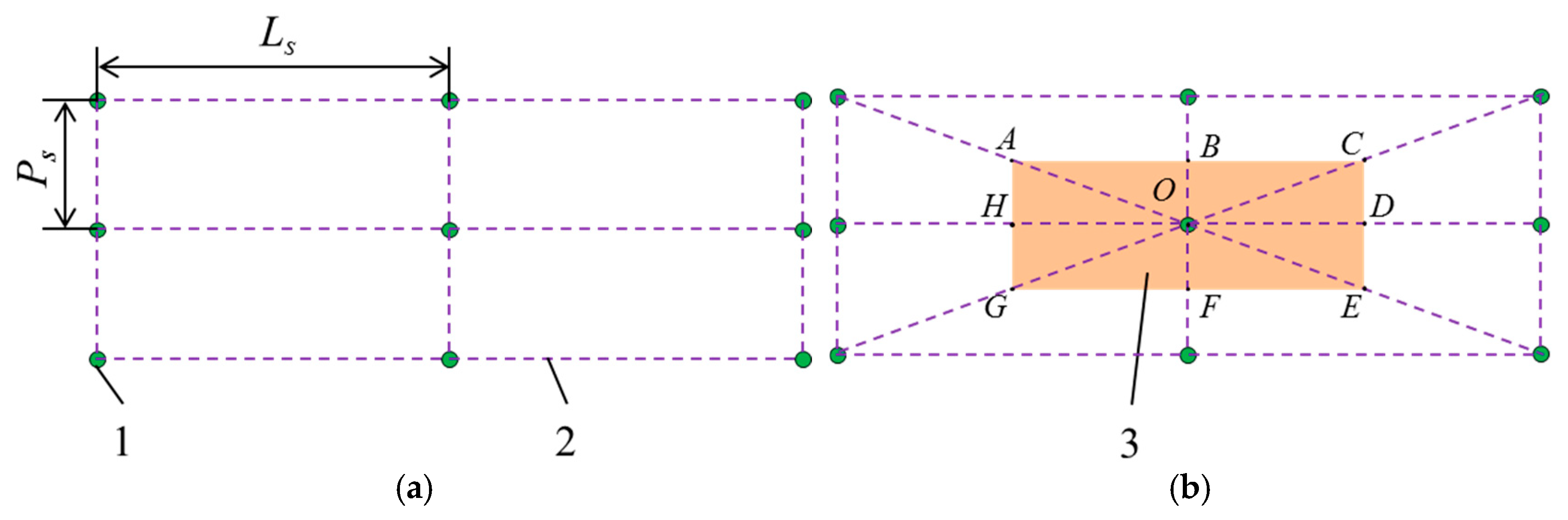
PsPlant-spacing of maize sowing (cm)xdPosition command issued by lateral translation motor
LsRow-spacing of maize sowing (cm)MxaDriving torque provided by lateral translation motor (N·m)
TzaTorque of the linear actuator (N·m)MyaDriving torque by longitudinal translation motor (N·m)
lsLead of the screw (m)fxaSliding friction resistance of lateral translation (N)
eLateral position tracking errorfyaSliding friction resistance of longitudinal translation (N)
u1Control law equationrxaForce arm length of the sliding friction force fxa (m)
s1Sliding surface equation for the lateral positioning mechanismryaForce arm length of the sliding friction force fya (m)
θ ^ 1 Estimated value of θ1tfTime required for the weeding robotic arm to move and align with the target point of the maize seedling (s)
Δ1Aggregate uncertainty encompassing external disturbances and unmodeled dynamicsbgThickness of the seedling-shielding fixed disc (mm)
rwRadius of the synchronous pulley (m)J1/θ1, J2, J3Moments of inertia of the lateral translation mechanism, longitudinal translation mechanism, and vertical telescopic mechanism during motion, respectively (kg·m2)

References

  1. Wang, A.; Zhang, W.; Wei, X. A review on weed detection using ground-based machine vision and image processing techniques. Comput. Electron. Agric. 2019, 158, 226–240. [Google Scholar] [CrossRef]
  2. Hamuda, E.; Glavin, M.; Jones, E. A survey of image processing techniques for plant extraction and segmentation in the field. Comput. Electron. Agric. 2016, 125, 184–199. [Google Scholar] [CrossRef]
  3. Zhang, X.; Wang, Q.; Wang, X.; Li, H.; He, J.; Lu, C.; Yang, Y.; Jiang, S. Automated detection of Crop-Row lines and measurement of maize width for boom spraying. Comput. Electron. Agric. 2023, 215, 108406. [Google Scholar] [CrossRef]
  4. Wang, X.; Zeng, S.; Luo, J.; Wang, S.; Luo, H. Species and Infestation Level of Weeds in Maize Fields of Bijie Mountain Locality. Weed Sci. 2024, 42, 17–30. [Google Scholar] [CrossRef]
  5. Oerke, E.C. Crop losses to pests. J. Agric. Sci. 2005, 144, 31–43. [Google Scholar] [CrossRef]
  6. Zhao, C. Prospect of Agricultural Robot. China Rural. Sci. Technol. 2019, 20–21. [Google Scholar]
  7. Zhao, C. Current situations and prospects of smart agriculture. J. South China Agric. University 2021, 42, 1–7. [Google Scholar] [CrossRef]
  8. EC-Weeder Intelligent Weeding Machine. Available online: https://www.lemken.cn/Proinfo.aspx?id=154 (accessed on 1 January 2025).
  9. Liu, G.; Sun, S.; Cheng, X.; Xu, J. Research and Design of 3ZS-2 Type Plowing Weeding Machine. J. Agric. Mech. Res. 1999, 2, 49–50 and 119. [Google Scholar]
  10. Li, N.; Chen, Z.; Zhu, C.; Zhang, C.; Sun, Z.; Li, W. System Design and Experiment of Electric Driven Weeding Robot. Trans. Chin. Soc. Agric. Mach. 2016, 47, 15–20+69. [Google Scholar] [CrossRef]
  11. Chen, Z.; Li, N.; Sun, Z.; Li, T.; Zhang, C.; Li, W. Optimization and experiment of intra-row brush weeding manipulator based on planetary gear train. Trans. Chin. Soc. Agric. Mach. 2015, 46, 94–99. [Google Scholar] [CrossRef]
  12. Gobor, Z.; Lammers, P.; Martinov, M. Development of a mechatronic intra-row weeding system with rotational hoeing tools: Theoretical approach and simulation. Comput. Electron. Agric. 2013, 98, 166–174. [Google Scholar] [CrossRef]
  13. Nørremark, M.; Griepentrog, H.W.; Nielsen, J.; Søgaard, H.T. Evaluation of an autonomous GPS-based system for intra-row weed control by assessing the tilled area. Precis. Agric. 2011, 13, 149–162. [Google Scholar] [CrossRef]
  14. Nørremark, M.; Griepentrog, H.W.; Nielsen, J.; Søgaard, H.T. The development and assessment of the accuracy of an autonomous GPS-based system for intra-row mechanical weed control in row crops. Biosyst. Eng. 2008, 101, 396–410. [Google Scholar] [CrossRef]
  15. Pérez-Ruíz, M.; Slaughter, D.; Fathallah, F.; Gliever, C.; Miller, B. Co-robotic intra-row weed control system. Biosyst. Eng. 2014, 126, 45–55. [Google Scholar] [CrossRef]
  16. Hou, X.; Chen, Y.; Guo, W. Machine vision-based navigation for a weeding robot. Trans. Chin. Soc. Agric. Mach. 2008, 39, 106–108. [Google Scholar]
  17. Guo, W.; Chen, Y. Fuzzy control based autonomous navigation for a weeding robot. Robot 2010, 32, 204–209. [Google Scholar] [CrossRef]
  18. Jia, H.; Li, S.; Wang, G.; Liu, H. Design and experiment of seedling avoidable weeding control device for intertillage maize (Zea Mays L.). Trans. Chin. Soc. Agric. Eng. 2018, 34, 15–22. [Google Scholar] [CrossRef]
  19. Slaughter, D.; Chen, P.; Curley, R. Vision guided precision cultivation. Precis. Agric. 1999, 1, 199–216. [Google Scholar] [CrossRef]
  20. Slaughter, D.; Giles, D.; Downey, D. Autonomous robotic weed control systems: A review. Comput. Electron. Agric. 2008, 61, 63–78. [Google Scholar] [CrossRef]
  21. Pantazi, X.; Moshou, D.; Bravo, C. Active learning system for weed species recognition based on hyperspectral sensing. Biosyst. Eng. 2016, 146, 193–202. [Google Scholar] [CrossRef]
  22. Sa, I.; Chen, Z.; Popović, M.; Khanna, R.; Liebisch, F.; Nieto, J.; Siegwart, R. weedNet: Dense Semantic Weed Classification Using Multispectral Images and MAV for Smart Farming. IEEE Robot. Autom. Lett. 2017, 3, 588–595. [Google Scholar] [CrossRef]
  23. Dyrmann, M.; Jørgensen, R.; Midtiby, H. RoboWeedSupport-Detection of weed locations in leaf occluded cereal crops using a fully convolutional neural network. Adv. Anim. Biosci. 2017, 8, 842–847. [Google Scholar] [CrossRef]
  24. Weed-Datasets of Zhangchuanyin. Available online: https://github.com/zhangchuanyin/weed-datasets (accessed on 1 May 2025).
  25. Jia, Z.; Zhang, M.; Yuan, C.; Liu, Q.; Liu, H.; Qiu, X.; Zhao, W.; Shi, J. ADL-YOLOv8: A Field Crop Weed Detection Model Based on Improved YOLOv8. Agronomy 2024, 14, 2355. [Google Scholar] [CrossRef]
  26. Liao, Y.; Li, C.; Liao, Q.; Wang, L. Research progress of seed guiding technology and device of planter. Trans. Chin. Soc. Agric. Mach. 2020, 51, 1–14. [Google Scholar] [CrossRef]
  27. Wang, Q.; Cao, X.; Wang, C.; Li, H.; He, J.; Lu, C. Research Progress of No/Minimum Tillage Corn Seeding Technology and Machine in Northeast Black Land of China. Trans. Chin. Soc. Agric. Mach. 2021, 52, 1–15. [Google Scholar] [CrossRef]
  28. Cao, X.; Wang, Q.; Li, H.; He, J.; Lu, C. Design and experiment of active rotating collective straw-cleaner. Trans. Chin. Soc. Agric. Eng. 2021, 37, 26–34. [Google Scholar] [CrossRef]
  29. Cao, X.; Wang, Q.; Li, H.; He, J.; Lu, C. Combined row cleaners research with side cutter and stubble clean disk of corn no-till seeder. Trans. Chin. Soc. Agric. Mach. 2021, 52, 36–44. [Google Scholar] [CrossRef]
  30. Transportation Machinery Design and Selection Manual Committee. Transport Machinery Design and Selection Manual, the Next Volume; Chemical Industry Press: Shanghai, China, 1999. [Google Scholar]
  31. Marcos-Andrade, D.; Beltran-Carbajal, F.; Rivas-Cambero, I.; Yañez-Badillo, H.; Favela-Contreras, A.; Rosas-Caro, J.C. Sliding Mode Speed Control in Synchronous Motors for Agriculture Machinery: A Chattering Suppression Approach. Agriculture 2024, 14, 737. [Google Scholar] [CrossRef]
  32. Peña-Fernández, A.; Colón-Reynoso, M.A.; Mazuela, P. Geometric Analysis of Greenhouse Roofs for Energy Efficiency Optimization and Condensation Drip Reduction. Agriculture 2024, 14, 216. [Google Scholar] [CrossRef]
  33. Lasalle, J.; Lefschetz, S. Stability by Lyapunov’s Direct Method; Academic Press: New York, NY, USA, 1961. [Google Scholar]
  34. Chu, B.; Shao, R.; Fang, Y.; Lu, Y. Weed Detection Method Based on Improved YOLOv8 with Neck-Slim. In Proceedings of the 2023 China Automation Congress (CAC), Chongqing, China, 17–19 November 2023; pp. 9378–9382. [Google Scholar] [CrossRef]
Figure 1. SEMSW with its specific position. Note: 1, SAM; 2, CWM; 3, End-effector bracket; 4, Transmission gearbox; 5, Weeding drive mechanism; 6, Seedling-shielding fixed disc; 7, Anti-cutting rotating disc; 8, RCU; 9, Anti-cutting rotating shield; 10, Shielding drive motor; 11, Rotating shield connector; 12, RCU axle; 13, RCU baffle; 14, Sliding flange bearing; 15, Open pin; 16, Seedling positioning sensor; 17, Support tube connector; 18, Contour cam linkage; 19, Gear fixation bearing; 20, Umbrella-shaped support connecting tube; 21, Rolling flange bearing; 22, Weeding-driven gear; 23, Effector fixation shaft; 24, Drive-rotating coupling; 25, Shielding motor enclosure; 26, SWC; 27, Drive rotary disc; 28, Cover of SAM; 29, TRWB; 30, Telescopic control axis; 31, Weed blade fixing bracket; 32, Fixed blade body; 33, Limit slider; 34, Telescopic blade body; 35, Weeding drive motor; 36, Weeding motor mounting bracket; 37, Coupler; 38, Weeding drive gear shaft; 39, Disc fixation nut; 40, Disc fixation bolt; 41, Soil surface.
Agriculture 15 01549 g001
Figure 2. Structure and control block diagram of weeding robotic arm. (a) Structure of weeding robotic arm; (b) Control block diagram of longitudinal (lateral) translation mechanism; (c) Control block diagram of vertical telescopic mechanism. Note: 1, Longitudinal translation mechanism; 2, Lateral translation mechanism; 3, Vertical telescopic mechanism; 4, Longitudinal translation motor; 5, Longitudinal motor-connecting shaft; 6, Synchronous belt pulley; 7, Synchronous belt; 8, Slide slider; 9, Lateral translation motor; 10, Lateral motor-connecting shaft; 11, Linear actuator.
Agriculture 15 01549 g002
Figure 3. Torque analysis of lateral translation mechanism. Note: Mxa is the riving torque provided by the lateral translation motor, N·m; rw is the radius of the synchronous belt pulley, m; fxa is the sliding friction resistance of lateral translation, N; and rxa is the length of the arm of the sliding friction force fxa, m.
Agriculture 15 01549 g003
Figure 4. The overview of dataset.
Agriculture 15 01549 g004
Figure 5. The overview of YOLOv8. Cited from: https://github.com/open-mmlab/mmyolo/blob/dev/configs/yolov8/README.md (accessed on 1 May 2025).
Agriculture 15 01549 g005
Figure 6. Key parameters of SAM. Note: 1, Seedling-shielding fixed disc; 2, Anti-cutting rotating disc; 3, RCU; 4, Anti-cutting rotating shield; 5, Shielding drive motor; 6, Rotating shield connector; 7, RCU axle; 8, RCU baffle; 9, Sliding flange bearing; 10, Open pin; 11, Seedling positioning sensor. D is the inner diameter of the seedling-shielding disc, mm; L is the seedling-shielding height, mm; d is the minimum inscribed-circle diameter d of the RCUs, mm.
Agriculture 15 01549 g006
Figure 7. The process of seedling-shielding with SAM. Note: 1, SAM; 2, Maize seedling; 3, Soil surface; 4, Partial schematic diagram. Lk is the height of the anti-cutting rotating shield, mm; Hm is the maximum height of maize at the 3–5 leaf stage, mm; h is the height of the SAM from the ground, mm; hc is the gap between RCUs and disc, mm; hs is the height of the RCU, mm; bx is the thickness of the anti-cutting rotating disc, mm; bg is the thickness of the seedling-shielding fixed disc, mm.
Agriculture 15 01549 g007
Figure 8. Key parameters of CWM. (a) Oblique view; (b) Front view. Note: 1, SWC; 2, Drive rotary disc; 3, Cover of SAM; 4, TRWB; 5, Umbrella-shaped support connecting tube; 6, Rolling flange bearing; 7, Weeding-driven gear; 8, Effector fixation shaft; 9, Drive-rotating coupling; 10, Shielding motor enclosure; 11, Gear fixation bearing; 12, Support tube connector; 13, Sliding flange bearing; 14, soil surface; 15, Contour cam linkage; d1 is the minimum inscribed-circle diameter of the TRWB, mm.
Agriculture 15 01549 g008
Figure 9. Minimum inscribed-circle diameter d1 of the TRWB. Note: 1, TRWB; 2, Drive rotary disk; 3, Cover of SAM; 4, SWC; 5, Non-cutting area. d1 is the minimum inscribed-circle diameter of the TRWB.
Agriculture 15 01549 g009
Figure 10. Agronomy conditions and minimum cutting area for maize sowing. (a) Agronomy conditions (top view); (b) minimum cutting area (top view). Note: 1, Maize plants; 2, Weeding segmentation grid; 3, Minimum theoretical cutting area.
Agriculture 15 01549 g010
Figure 11. The process of seedling-shielding with SAM. (a) Structural parameters of cam contour curve; (b) Ls = 60 cm, Ps = 22 cm; (c) Ls = 55 cm, Ps = 27 cm. Note: 1, Cam contour curve; 2, Other situations cutting area.
Agriculture 15 01549 g011
Figure 12. Design of TRWB structure and size chain. (a) Schematic diagram of TRWB; (b) dimensional chain design of TRWB. Note: 1, Telescopic control axis; 2, Weed blade fixing bracket; 3, Fixed blade body; 4, Limit slider; 5, Telescopic blade body; 6, Sliding flange bearing; 7, Open pin.
Agriculture 15 01549 g012
Figure 13. Maize image segmentation. (a) Original image; (b) segmentation effect.
Agriculture 15 01549 g013
Figure 14. Training results of weed detection model. Note: Precision measures the model’s ability to minimize false positives, a critical metric for avoiding crop damage during weeding; Recall reflects the completeness of weed detection, essential for preventing missed weeds; mAP50 (mean average precision at 50% IoU) demonstrates the general robustness of detection; and mAP50-95, a comprehensive evaluation across IoU thresholds ranging from 50% to 95%, indicates the precision of object localization.
Agriculture 15 01549 g014
Figure 15. The results of weed detection.
Agriculture 15 01549 g015
Figure 16. Field experimental site. (a) Field test environment; (b) SEMSW’s bench platform in the field.
Agriculture 15 01549 g016
Figure 17. Weeding effect of SEMSW. (a) Before weeding operation; (b) after weeding operation.
Agriculture 15 01549 g017
Table 1. Weed detection model metric.
MetricsValues
Precision0.951
Recall0.844
mAP500.950
mAP50-950.819
Table 2. Main parameters of field tests.
ItemsParametersValues
Maize seedlingsAverage plant height/mm203
Average stem diameter/mm9.8
WeedsHeight range/mm2~5
Stalk diameter/mm0.1~0.3
Moisture content/%66.17
0~100 mm soil layerPenetration resistance/kPa326
Moisture content/%19.83
Bulk density/(g·cm−3)1.28
Temperature/°C18.3
Table 3. Result of the WRR tests.
MetricsValues/%Range/%Coefficient of Variation/%Standard Deviation
WRR88.378.6~94.16.25.44
Disclaimer/Publisher’s Note: The statements, opinions and data contained in all publications are solely those of the individual author(s) and contributor(s) and not of MDPI and/or the editor(s). MDPI and/or the editor(s) disclaim responsibility for any injury to people or property resulting from any ideas, methods, instructions or products referred to in the content.

