1. Introduction
Broccoli (
Brassica oleracea var.
italica), a high-economic-value cruciferous vegetable, has seen continuous expansion in global cultivation. According to FAO (Food and Agriculture Organization of the United Nations) statistics, China’s broccoli planting area reached 490,000 hectares with a yield exceeding 9.71 million tons in 2023 [
1]. However, its harvesting remains highly reliant on manual labor, facing dual pressures of labor shortages and rising costs [
2]. With the exacerbation of population aging, labor supply issues have become increasingly severe. Developing selective harvesting machinery for broccoli has thus become an urgent need for industrial sustainability.
While mechanized harvesting research for vegetables has advanced, such as for white radish [
3] and chili peppers [
4], and cabbage harvesting technologies are relatively mature [
5], most existing equipment employs one-time non-selective harvesting modes [
6,
7], which are incompatible with broccoli’s staggered maturity, requiring batch-wise selective harvesting. Selective harvesters typically integrate three core modules—visual detection, positioning systems, and end effectors—to enable picking based on crop maturity and size. Although selective end effectors have been widely studied [
8,
9,
10], such as tomatoes [
11], sweet peppers [
12], grapes [
13,
14], button mushrooms [
15], and apples [
16], direct application to broccoli is challenging due to its thick stem (requiring high cutting force) and bulky head (posing unique gripping challenges).
Roboveg designed a multi-DOF manipulator-based end effector using cavity sleeving and single-blade transverse cutting, but its large cavity structure is prone to field interference [
17]. Sami AGTech industry proposed a flexible gripping system combined with high-pressure waterjet cutting, which is effective but bulky, costly, and water-intensive—unsuitable for China’s agricultural context [
18]. Japan’s Mycom prototype removes leaves before stem clamping, but it only adapts to single-row planting, conflicting with China’s mainstream double/multi-row agronomy [
19]. Xu et al. [
20] developed an under-actuated dual-blade cutter with self-adaptive gripping rods, which achieved an 84% picking success rate in laboratory tests. Their experiments used leafless broccoli heads in simplified conditions without field validation. Its picking reliability needs to be further verified in field tests. Zhao et al. [
21] improved cutting success using Delta robot-based dual-ring blades but produced uneven cut surfaces. Kang et al. [
22] achieved 90% success for heads <15 cm in diameter with a humanoid pinching cutter, but success rates dropped to 63.63% for larger heads (>15 cm) or thick stems (>50 mm). Song et al. [
23] proposed a centering cutter with five-blade opposing cuts (0.6 s/cycle), but its extreme positioning precision requirement and post-harvest detachment issues limit field applicability.
Existing fruit/vegetable harvesting end effectors are ill-suited for broccoli, and current broccoli-specific designs have significant limitations: large cavity cutters prone to interference; under-actuated grippers with unreliable grasping; waterjet systems with high resource consumption; humanoid pinchers with poor size adaptability; and centering cutters with strict positioning demands. This study presents an innovative multi-cylinder coordinated end effector based on a Cartesian manipulator. Building on cavity and transverse cutting principles, key improvements include the following:
Dual-blade coordinated cutting to enhance efficiency/reliability while reducing single-side profile via bilateral stroke distribution, minimizing field interference.
Integrated grasp-cut structure with multi-rod dynamic wrapping cavities (replacing rigid cylinders) to further reduce operational envelope.
Optimized cylinder actuation timing to minimize maximum profile and improve success rates via trajectory optimization.
Regarding manipulator architectures, while Cartesian coordinate manipulators have been tested for selective harvesting, their adoption is constrained by challenges in complex field environments. Notably, broccoli heads grow upright, with larger heads being more exposed, leading to relatively regular spatial poses. Cartesian coordinate manipulators, with their simple structure, deterministic trajectories, low cost, and easy maintenance, show potential for broccoli harvesting compared with high-cost, complex multi-DOF manipulators. Cartesian architectures are theoretically suitable for broccoli’s growth characteristics.
Field tests demonstrated stable performance of the developed mechanism, marking a critical step toward industrializing selective broccoli harvesting technology.
3. Mechanical Analysis of Broccoli Stems and Structural Optimization of End-Effector
The design of the end effector is grounded in the agronomic parameters of broccoli cultivation, as summarized in
Table 1. These parameters encompass critical factors such as plant spacing, row spacing, maximum diameter of broccoli heads, and stem physical properties, which serve as the foundational guidelines for optimizing the structural dimensions of the end effector and its operational performance.
3.1. Maximum Cutting Force Experiment
3.1.1. Introduction to the Maximum Cutting Force Test Rig
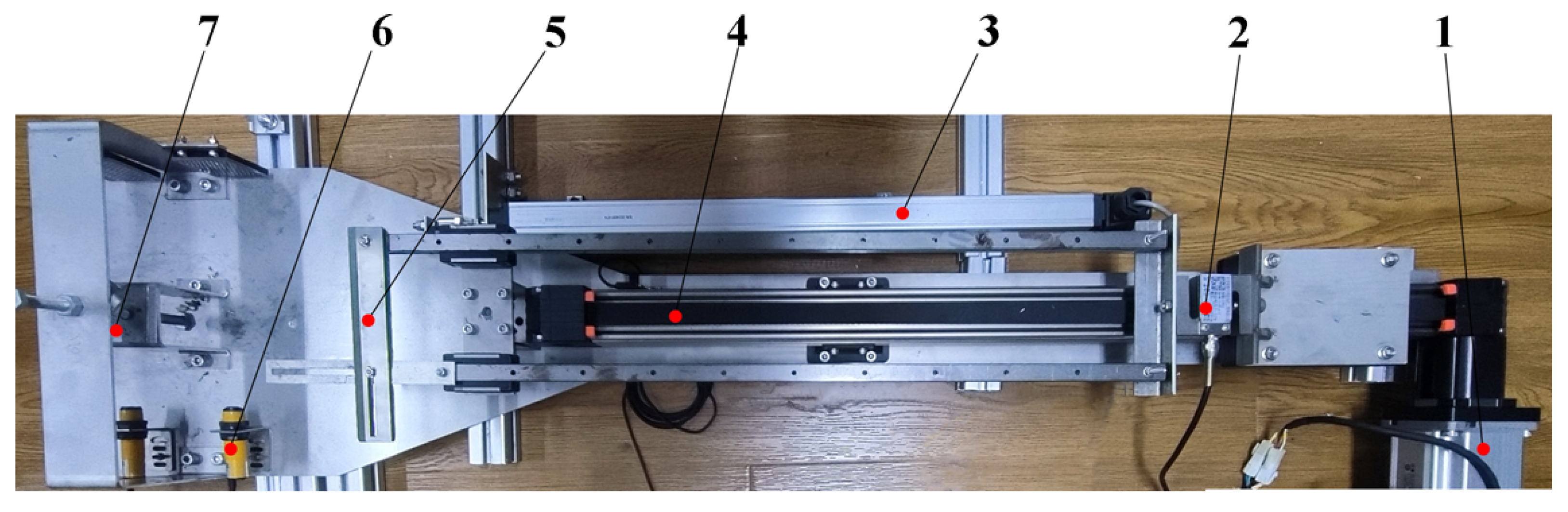
For the purpose of testing the maximum cutting force of broccoli stems, a high-precision cutting test device was independently developed in this study, as shown in
Figure 3. The rig integrates dual-sensor data acquisition functionality. Through a combination of a servo motor (labeled as 1 in
Figure 3) and a synchronous belt linear module (labeled as 4 in
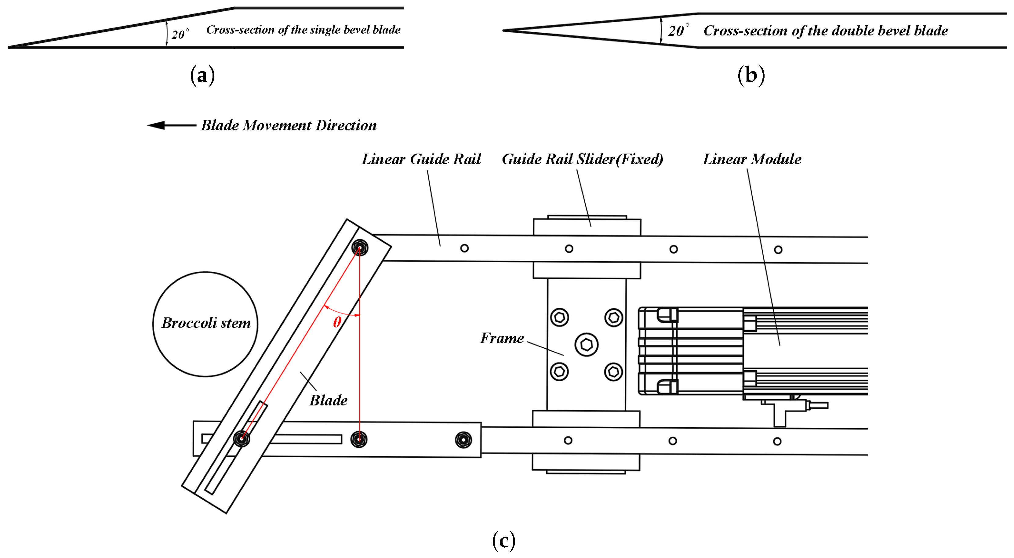
Figure 3), precise speed regulation of the blade within the range of 0 mm/s~2000 mm/s is achieved. A specially designed carbon steel blade (with a wedge angle of 20°) is installed at the front end of the guide rail. The sliding cutting angle parameters can be adjusted by changing the installation position of the blade, and the rig also supports the replacement of blades with different shapes. The definitions of the two blades’ wedge angles and sliding cutting angle are shown in
Figure 4a–c.
Additionally, the rig is equipped with a multi-dimensional sensing system: a force sensor (labeled as 2 in
Figure 3) with a measuring range of 0 N~200 N is used to monitor the reaction force along the movement direction of the slider in real time; a displacement sensor (labeled as 3 in
Figure 3) is connected to the blade through a floating joint to record the cutting displacement; and a photoelectric speed-measuring sensor (labeled as 6 in
Figure 3) is employed for speed verification. Data from each sensor are synchronously collected by a host computer, and the original electrical signals are stored in ’.csv’ format.
During the test, each of the broccoli stem samples is fixed in the broccoli stem clamping station (labeled as 7 in
Figure 3) to ensure that the distance from the cutting surface to the bottom of the sample stem is constantly 10 mm. In the operation process, the servo motor drives the blade to perform linear cutting according to preset parameters, and the sensors collect force-displacement data synchronously. With its modular design and precise control, this rig provides a reliable experimental platform for the study of the cutting mechanical properties of broccoli.
3.1.2. Results and Analysis of the Maximum Cutting Force Experiment
Samples were commercially procured from local markets, with 10 cm~15 cm intact stems (leafless). They were transported under frozen preservation with crushed ice and thawed at room temperature for 2 h prior to testing, maintaining a moisture content to ensure biomechanical validity.
This study systematically investigated the cutting mechanical properties of broccoli stems through a full-factorial experimental design. Based on the experimental factor level table (
Table 2), 54 full-factorial test groups were constructed. Analysis of variance (ANOVA) results (
Table 3, based on
Table 4) showed that blade type (
p < 0.001), blade thickness (
p < 0.001), and sliding cutting angle (
p = 0.002) had significant effects on maximum cutting force, while cutting speed (
p = 0.647) did not reach statistical significance. Among them, blade type and thickness exhibited the most prominent main effects, requiring priority in design parameter optimization. The sliding cutting angle had a relatively secondary influence, allowing performance matching through local adjustments. Two-factor interaction analysis revealed no significant second-order factor interactions (
p > 0.05).
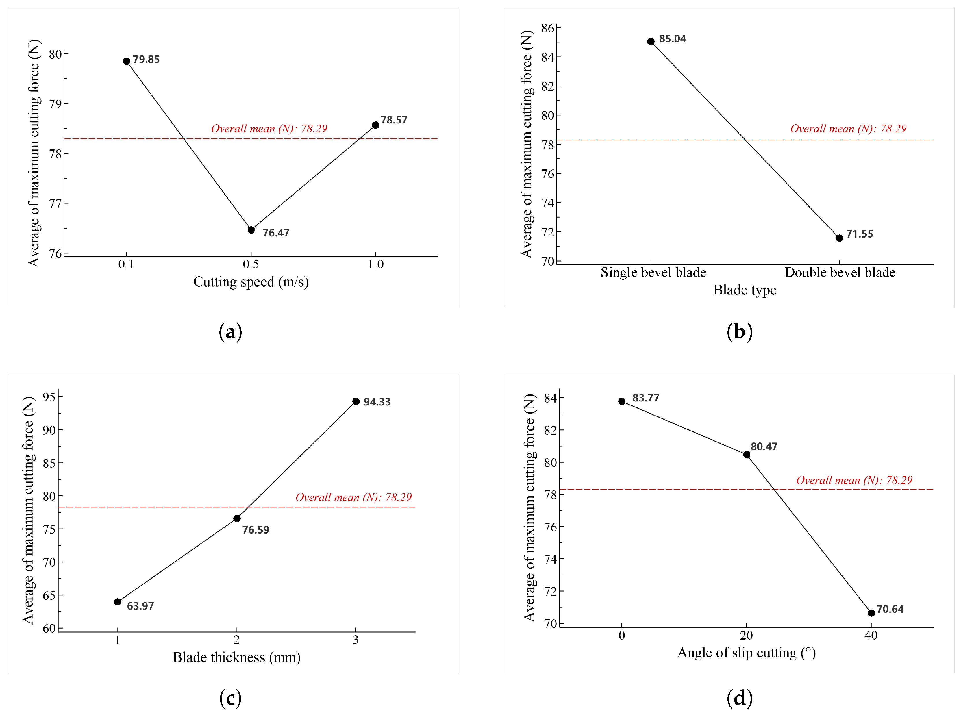
Analysis of the main effect on maximum cutting force (
Figure 5) reveals the following influences of individual factors. With respect to cutting speed (shown in
Figure 5a), a non-linear relationship with the maximum cutting force is observed within the range of 0~1000 mm/s, exhibiting distinct variation trends. For blade type (shown in
Figure 5b), the double-bevel blade type results in a lower maximum cutting force compared with the single-bevel blade type. Regarding blade thickness (shown in
Figure 5c), within the range of 1~3 mm, the maximum cutting force increases with increasing thickness, with the 1 mm thickness yielding the smallest maximum cutting force, thus representing an optimal parameter choice for design optimization. As for the sliding cutting angle (shown in
Figure 5d), a negative correlation with the maximum cutting force is evident in the range of 0~40°—specifically, the maximum cutting force decreases as the sliding cutting angle increases. Combining trend analysis from the main effect diagram of maximum cutting force (
Figure 5), a preliminary optimization combination was proposed as a blade thickness of 1 mm, a double-bevel blade type, and a sliding cutting angle of 0°.
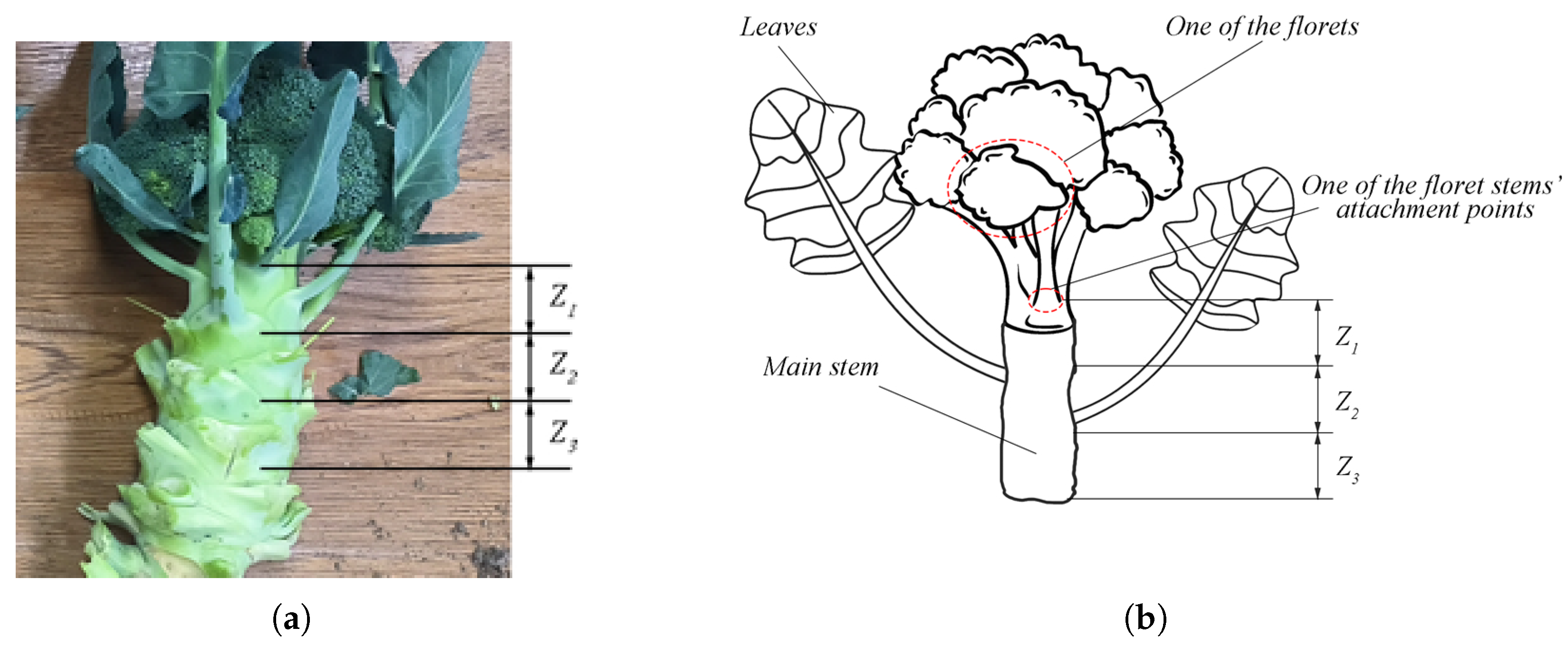
To further validate key parameters and provide a mechanical basis for structural design, ten parallel experimental groups on cutting positions were conducted under the conditions of 1 mm blade thickness, double-bevel blade of blade type, and 0° sliding cutting angle. During the experimental procedure, the stems of each broccoli plant were sectioned into 190 three samples according to the zoning criteria depicted in
Figure 6a,b and
Table 5, corresponding to the
,
, and
zones, respectively. Subsequently, a maximum cutting force test was performed on these samples, and the experimental results are presented in
Table 6.
The “
” zone extended from 0 mm to 30 mm from the bottom of the lowermost floret stem, the “
” zone covered the range of 31 mm to 60 mm, and the “
” zone corresponded to the depth of 61 mm to 90 mm. The detailed delineation criteria for each zone are illustrated in
Table 5.
ANOVA confirms that cutting position has a highly significant statistical effect on maximum cutting force (
p < 0.001). As shown in
Table 6, ten groups of parallel experiments on cutting positions show that under the specific conditions of 1 mm blade thickness, double-bevel blade of blade type, and 0° sliding cutting angle, cutting experiments on broccoli stems yielded maximum force values ranging from 30 N to 130 N. Spatial analysis of individual plants revealed a non-linear increase in maximum cutting force with distance from the bottom of the head (The coordinate origin for stem zoning). However, maximum cutting forces are below 100 N within Zones
and
. This spatial force distribution directly informs the design of the end-effector, as the agronomically required 30 mm~40 mm stem retention aligns with Zone
, where forces remain safely below the 100 N threshold.
The critical finding—that cutting forces are constrained within 100 N for positions 0 mm~60 mm below the bottom of the flower head—establishes a foundational design parameter: end-effectors must be engineered to sustain loads of at least 100 N within this interval. This quantitative guideline ensures both efficient harvesting and mechanical durability in robotic systems.
Synthesizing the experimental results, this study established a tool design parameter system for broccoli harvesting end effectors: 1 mm blade thickness, double-bevel blade of blade type, 0° sliding cutting angle, combined with an optimized cutting position 0 mm~60 mm below the bottom of flower heads. Under these conditions, the maximum cutting force did not exceed 100 N. These conclusions provide critical technical parameters for the mechanical structure design and power system matching of end effectors. Specifically, morphological data (including stem diameter, flower head diameters, and head height, as shown in
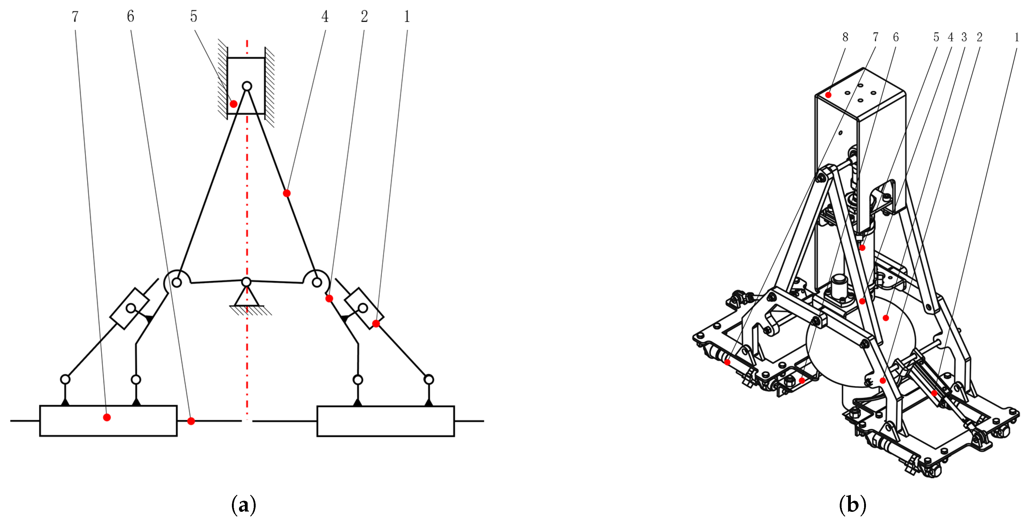
Table 1) were first used to define the range of feasible design parameters, ensuring the end-effector could adapt to the morphological characteristics of broccoli. Based on the conclusions drawn from the aforementioned experiments regarding cutting forces—using a 1 mm thick double-bevel blade with a 0° sliding cutting angle and an optimal cutting position 0 to 60 mm below the base of the flower head, under which the maximum cutting force remains within 100 N—the selection of the blade cylinders (labeled as 1 in
Figure 1) and its arrangement have been determined.
3.2. Width Design of End Effector at the Pre-Extension Stage of Four-Blade Cylinders
The maximum cutting force test experiments determined the optimized design parameter combination for the end effector as follows: blade thickness of 1 mm, blade width of 30 mm, double-bevel blade of blade type, sliding cutting angle of 0°, with a required cutting force of at least 100 N.
The width of the end effector at the pre-extension stage of four-blade cylinders directly affects its adaptation in field environments. Based on the range of plant spacing, row spacing, and head diameter summarized in
Table 1, the width of the end effector must be restricted to 580 mm (290 mm per side). As shown in
Figure 7, its width
B is composed of five components. The calculation formula for
B is given by Equation (
1):
where the following is true:
B: Width of the end effector, mm;
: Other installation width, mm;
: Cylinder installation width, mm;
: Blade installation width, mm;
: Tolerance gap, mm;
r: Stem radius of broccoli, mm.
is a constant (value: 36 mm) determined by the installation method of the position adjustment cylinders (labeled as 1 in
Figure 1).
is the installation width of the blade cylinders (labeled as 1 in
Figure 1), determined by the cylinder model and installation method.
is the blade installation width—since rectangular blades are used, this value is 15 mm.
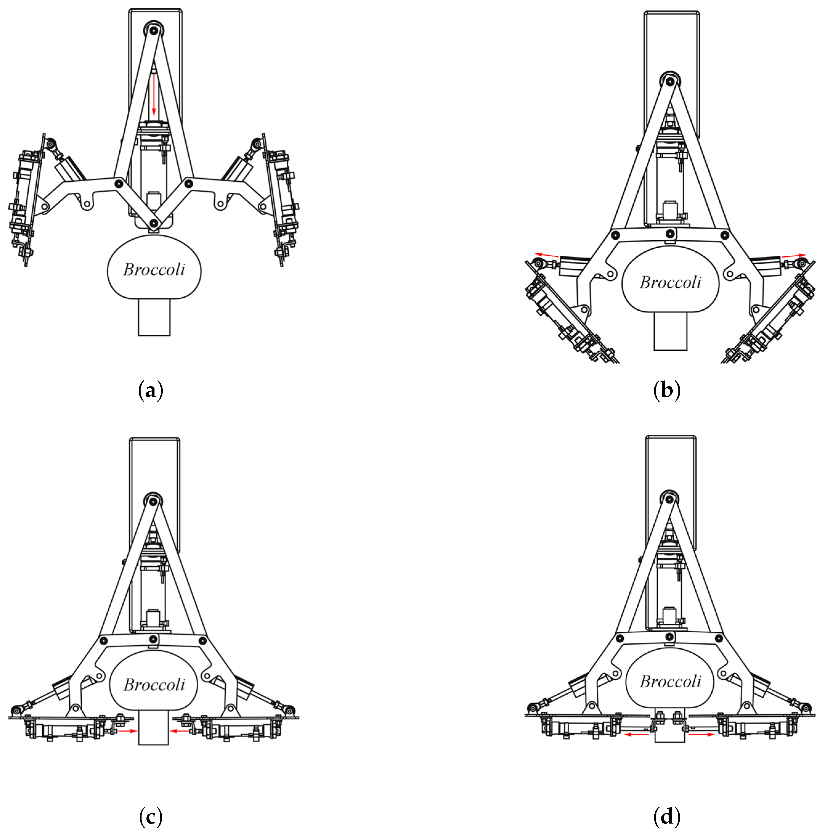
is the tolerance gap, referring to the distance between the blade and the surface of the broccoli stem. When the end effector assumes the posture depicted in
Figure 2c, generally set to 10 mm,
r is the stem radius of the broccoli. According to the broccoli stem diameter range of 40 mm~60 mm specified in
Table 1,
r is taken as 30 mm based on the maximum stem diameter. The stem radius of 30 mm (corresponding to 60 mm diameter) was selected based on measurement. This choice not only covers the maximum operational scenario but also creates a 5 mm~10 mm tolerance gap for smaller stems. Among them, the sum of
and
r is called the cutting stroke
, which is equal to the effective stroke of the blade cylinder (labeled as 1 in
Figure 1), as shown in Equation (
2).
Thus, the cutting stroke
is determined to be 40 mm, and the formula for calculating the end effector width
B is given by Equation (
3).
In Equation (
3),
and
are both constant values, while the end effector width
B is determined by
and
. Based on the conditions of a cutting stroke of 40 mm and a maximum cutting force of not less than 100 N, the model and installation method for the blade cylinders were selected, leading to
being specified as 157 mm.
In summary, with set at 36 mm, at 157 mm, at 15 mm, and at 40 mm, B is calculated as 496 mm (248 mm per side), which meets the requirement: the total width of the end effector must be restricted to 580 mm (290 mm per side).
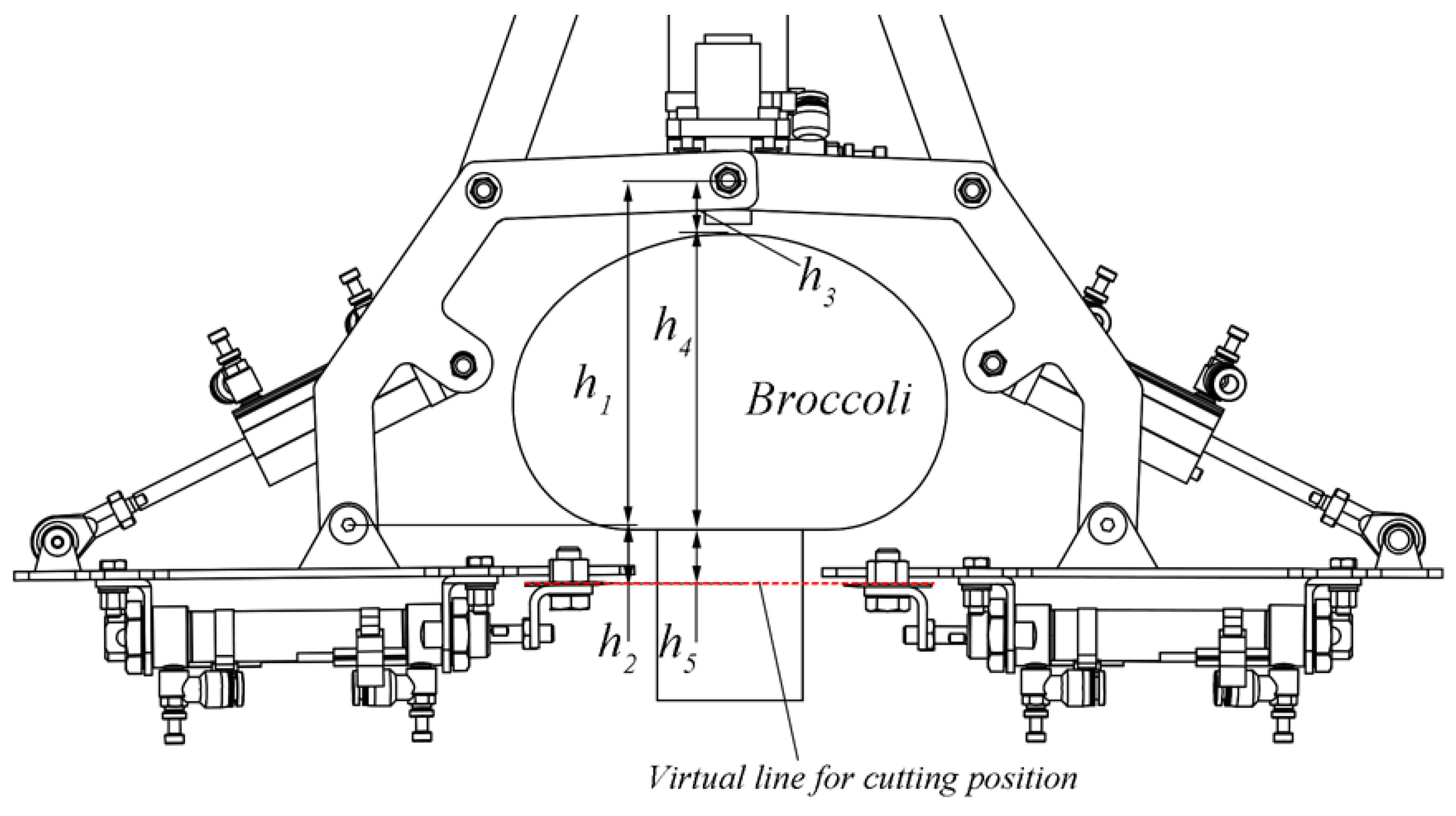
3.3. Key Dimensional Parameter Design of Connecting Rod
Experiments revealed a highly significant correlation between the cutting position and the maximum cutting force. Within the range of 0 mm~60 mm below the broccoli head, the maximum cutting force remained consistently below 100 N. In this section, we analyze the composition of cutting positions based on the morphological characteristic range of broccoli heads and the obtained conclusions, thereby designing the key dimensional parameters of the connecting rod (labeled as 1 in
Figure 1). The calculation method for the cutting position is given in Equation (
4).
where the following is true:
: Key dimensional parameter of the connecting rod, mm;
: Necessary blade installation distance, determined by mounting configuration, mm;
: Top clearance between the broccoli head and end effector, mm;
: Height of the broccoli head, mm;
: Distance from the cutting position to the base of the broccoli head, mm.
The cutting position analysis diagram takes the fixed hinge point of the connecting rod as the coordinate origin.
is defined as the vertical distance from the fixed hinge point to the connecting hinge point of the blade mounting plane. In Equation (
4),
is a constant (value: 17 mm) determined by the mounting dimensions of other components. Thus,
directly determines the blade’s cutting position, as illustrated in
Figure 8. As an adjustable parameter,
is tentatively set to 15 mm to ensure a safety clearance of at least 5 mm from the broccoli head apex. The parameter
was designed by integrating mechanical structural constraints and dynamic adjustment logic, with its value determined by the connecting rod width (10 mm from the center to the edge) and a 5 mm safety margin, designed to avoid rigid collision between the broccoli top and the connecting rod edge. It is not a fixed threshold but can be dynamically adjusted through the Z-axis depth control of the Cartesian manipulators, enabling the safety margin to adaptively change within 5 mm~10 mm for different flower head heights, ensuring both cutting safety and operational flexibility. Statistical analysis of 54 broccoli heads (diameter range: 130 mm~160 mm) showed that 90% exhibited heights between 90 mm~130 mm, with 62.96% falling within 110 mm~130 mm. Given the desired cutting position range (0 mm~60 mm below the head):
For heads 120 mm~130 mm tall, a cutting position at 140 mm corresponds to 0 mm~10 mm below the head. For heads 90 mm~100 mm tall, this position translates to 30 mm~40 mm below the head. Both scenarios satisfy the experimental criteria. Therefore, was set to 130 mm and to 0 mm~30 mm. The optimal cutting position was determined to be 160 mm (ranging from 145 mm to 175 mm). When is set to 17 mm, the corresponding should be 143 mm.
3.4. Trajectory Simulation and Optimization
We employed SolidWorks 2023 as the core tool to conduct operational simulations of the end effector’s motion and perform interference checks on the operating range of the Cartesian manipulators. The specific methods and their advantages are as follows:
(1) Trajectory analysis: SolidWorks Motion 2023 was used for trajectory simulation of the end effector. By setting the motion parameters and timing of each cylinder, the trajectory changes were accurately simulated. The software can output parameters such as the running trajectory and coordinates of the characteristic points of the end effector model in real time, which can be processed with Origin 2024 to generate trajectory comparison graphs (such as
Figure 9) after being output as table files. The running animation intuitively displays the operation process, assisting in trajectory optimization.
(2) Interference checking: Considering the vertical trajectory characteristics of the Cartesian manipulators, we defined the motion boundaries of each axis of the manipulator (e.g., maximum stroke range) using the “Mate” function in the SolidWorks 2023 assembly environment. Then, we determined the range where the manipulator can move freely without interfering with other parts (such as the chassis) by setting the coordinates of each axis of the manipulator, thus completing the interference check.
SolidWorks Motion is highly integrated with the 3D modeling module, enabling the entire process from model construction to simulation analysis without data conversion, which significantly improves design efficiency; its visual interface facilitates quick parameter adjustment and scheme verification. Through feedback from simulation results, design parameters (such as cylinder installation methods) can be quickly iterated, eliminating interference issues in the design stage and reducing the cost and time of physical prototype debugging.
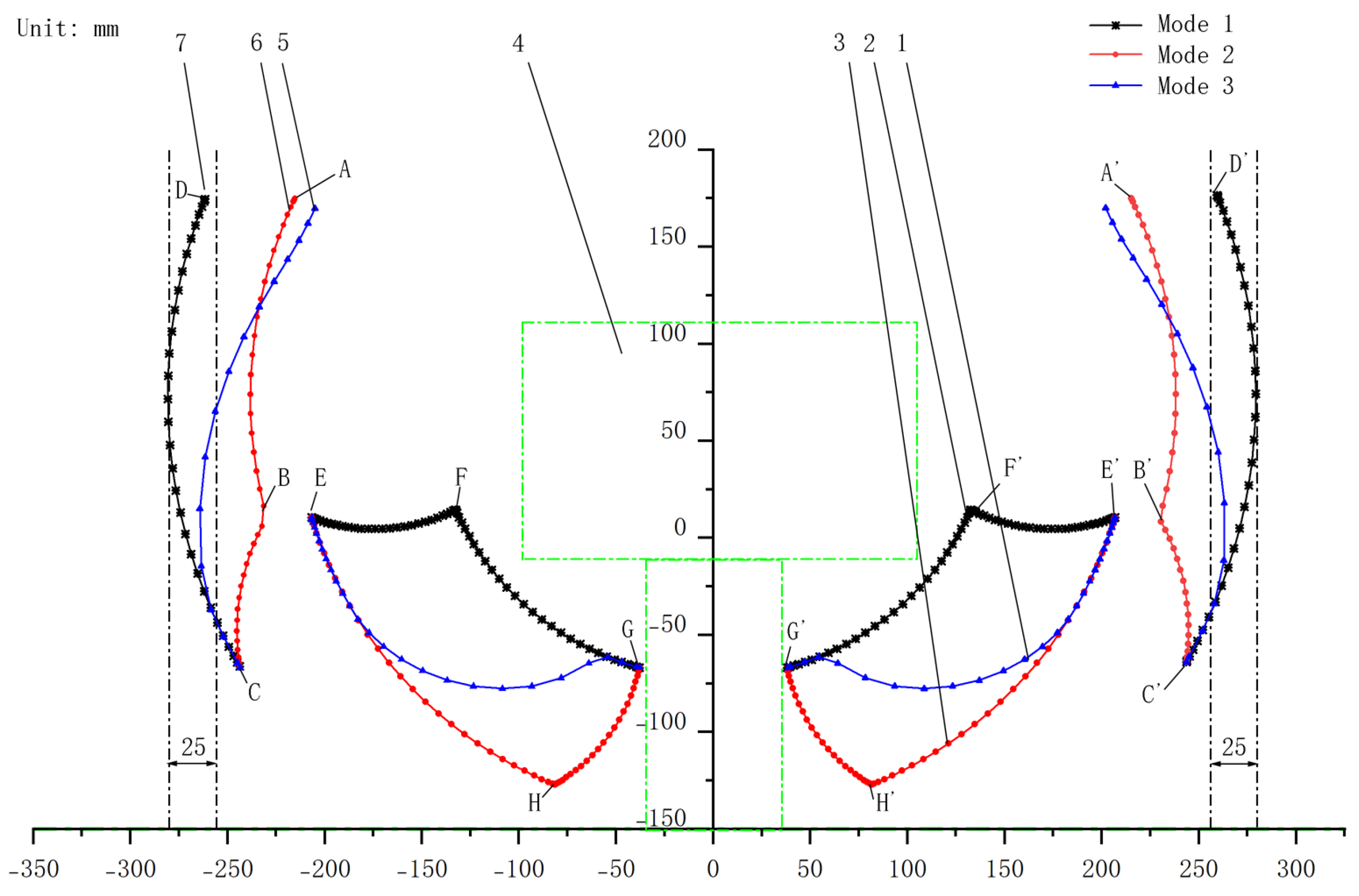
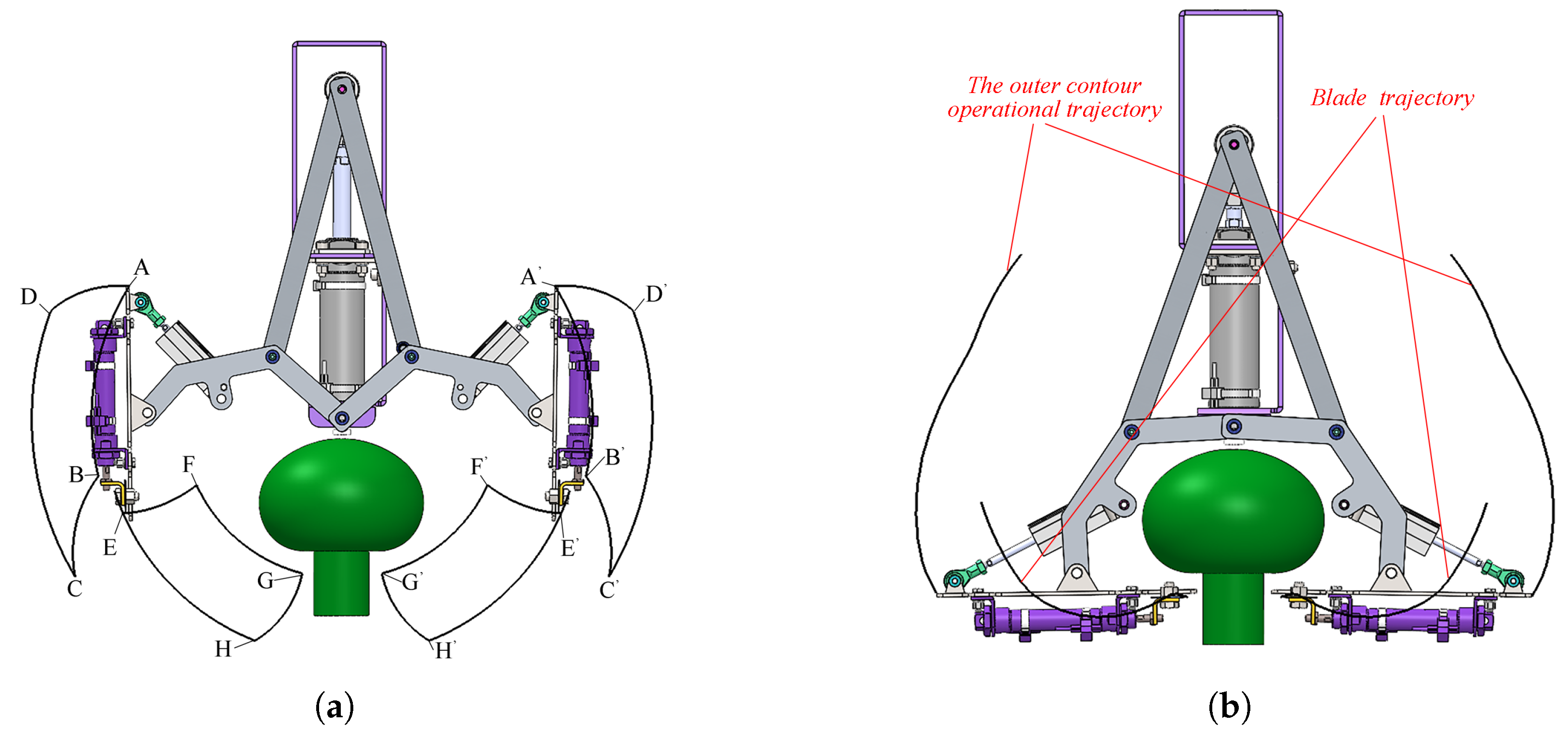
As shown in
Figure 9,
Figure 10a and
Figure 10b, the integrated multi-cylinder end effector can exhibit various operational trajectories depending on the extension timing of the position adjustment cylinders (labeled as 1 in
Figure 1). In operation Mode 1, the position adjustment cylinders (labeled as 1 in
Figure 1) are first extended, and once they reach full extension, the push rod cylinder (labeled as 1 in
Figure 1) is retracted. In operation Mode 2, the push rod cylinder (labeled as 1 in
Figure 1) is retracted first, and after achieving full retraction, the position adjustment cylinders (labeled as 1 in
Figure 1) are extended. In operation Mode 3, the retraction of the push rod cylinder (labeled as 1 in
Figure 1) is initiated first, and during this retraction process, the extension of the position adjustment cylinders (labeled as 1 in
Figure 1) is activated. The activation timing of the position adjustment cylinders (labeled as 1 in
Figure 1) relative to the push rod cylinder’s (labeled as 1 in
Figure 1) retraction stroke determines distinct operational trajectories.
As shown in
Figure 9, in operation Mode 1, the outer contour operation trajectory of the end effector is DC (D’C’), and the operation trajectory of the blade is EFG (E’F’G’). In operation Mode 2, the outer contour operation trajectory of the end effector is ABC (A’B’C’), and the operation trajectory of the blade is EHG (E’H’G’). When harvesting in Mode 1, the operational width of the outer contour operation trajectory is larger, prone to damaging the surrounding environment. When harvesting in Mode 2, the operational width of the outer contour operation trajectory is smaller, showing better adaptability to field environments, but in the final stage (H to G segment), it is easily blocked by the leaves of the broccoli, causing the cutting blades to fail to reach the position. Therefore, it is necessary to adjust the extension timing of the position adjustment cylinders (labeled as 1 in
Figure 1) according to field conditions to change the operational trajectory of the end effector.
Measured results show that the extension action of the position adjustment cylinders (labeled as 1 in
Figure 1) takes approximately 0.36 s, and the retraction of the push rod cylinder (labeled as 1 in
Figure 1) takes approximately 0.85 s. The position adjustment cylinder (labeled as 1 in
Figure 1) starts to operate when the blade edge is below the bottom of the flower head, generating the operational trajectory curve of the end effector as shown in
Figure 9, where the green contour drawn based on the broccoli head diameter, stem diameter, and broccoli head height in
Table 1 represents the possible area of broccoli plants.
In operation Mode 3, the operational trajectory curve of the end effector is generated when the position adjustment cylinders (labeled as 1 in
Figure 1) start to operate 0.40 s after the retraction action of the push rod cylinder (labeled as 1 in
Figure 1) is initiated.
Simulation of the end effector’s operation trajectory shows that the end effector operating in Mode 3 can adapt to broccoli heads with a diameter of 200 mm, with the maximum unilateral width of the outer contour operation trajectory reduced by approximately 25 mm compared with operating in Mode 1, and compared with operating in Mode 2, the end effector operating in Mode 3 is less likely to be blocked by plant stems and leaves. Consequently, Mode 3 is selected as the operational mode for field harvesting trials due to its adaptability to complex environmental conditions.
6. Discussion
To address the challenges of broccoli selective harvesters, this study presents an integrated grasp-cut end effector, integrating transverse cutting and a foldable grasping cavity.
This study determined the key design parameters of the end effector through maximum cutting force tests: when the blade thickness is 1 mm, a double-bevel structure is adopted, the sliding cutting angle is 0°, and the cutting position is in the range of 0 mm~60 mm below the bottom of the flower heads, the maximum cutting force can be controlled within 100 N. This design criterion ensures the cutting success rate of the end effector and can be directly applied by researchers. It is noteworthy that ANOVA of the multi-factor mixed-level test of maximum cutting force (shown in
Table 3) and the main effect plot of the sliding angle (shown in
Figure 5d) suggested 40° as the theoretically optimal parameter. However, during the structural design of the end-effector, we found that a 40° sliding angle would require an excessive width of the end-effector
B beyond the allowable operational range. To address this, we tried a 0° sliding angle in the cutting position test and obtained the corresponding maximum cutting force data. The results showed that the measured forces fully met the load requirements for blade cylinder (labeled as 1 in
Figure 1) selection, validating the 0° sliding angle as the engineering-feasible solution. This compromise between theoretical optimization and practical constraints ensures both performance and operational viability. Testing on 50 broccoli plants yielded a 96% cutting success rate and a 100% operational success rate. When combined with data from 30 field-tested plants, the overall practical operational success rate reached 97.5% (78 out of 80). A post-hoc power analysis was conducted using G*Power 3.1.9.7 software with the following parameters: one-tailed test, effect size (
g) of 0.09 (derived from the difference between the observed success rate of 96% and the benchmark value of 87%), significance level (
) of 0.05, total sample size (
n) of 80, and a constant proportion set at 86.96% (comprehensive cutting success rate from Kang et al. [
22]). The analysis results showed a lower critical success count of 75, meaning statistical significance could be confirmed when the number of successful cases was 75 or more. The actual test power reached 0.8988 (approximately 90%), indicating that the sample size had nearly a 90% probability of detecting a true effect. The actual
value was 0.0426, which is below the preset 0.05, further controlling the risk of false positives. Given the test results (total successful cases > 75, success rate > 93.75%), the cutting success rate of the end-effector is significantly higher than the 87% benchmark, demonstrating high statistical reliability and robustness.
Regarding the relevance between the force data in
Table 4 and the design parameter—stem diameter—we would like to clarify as follows: The stem diameter range of 40 mm~60 mm in
Table 1 is not a variable in the cutting experiments but rather the design input conditions for the end-effector. The core objective of this study is to obtain the maximum cutting force under optimal working conditions (such as blade thickness and blade type) within this diameter range to meet the cutting requirements of all samples to the greatest extent. Specifically, through preliminary statistics, it was found that the stem diameters of common broccoli in the market are distributed within 40 mm~60 mm, which is significantly representative. Based on the maximum cutting force test of stems with diameters ranging from 40 mm to 60 mm under certain conditions (1 mm blade thickness, double-bevel blade, 0° sliding cutting angle, combined with an optimized cutting position 0 mm to 60 mm below the bottom of flower heads, where the maximum cutting force did not exceed 100 N), a blade cylinder with a bore diameter of 16 mm and an air pressure of 0.5 MPa (with a theoretical driving force of approximately 80 N) was selected, and a single-side dual-cylinder drive was adopted to form a 50% cutting force redundancy (design threshold of approximately 160 N). Despite the lack of control over stem diameter variables in the cutting experiments, the rationality of this design has been verified in the following ways: In field trials (n = 28), the cutting success rate reached 92.86 %, and no failure due to insufficient cutting force occurred during 2 h of continuous operation; in a large number of stem cutting tests (n = 84), the measured maximum cutting force was always lower than 160 N, indicating that the 50% redundancy can meet actual needs. There are indeed certain empirical limitations in the current setting of the redundancy value. In future research, we will improve the accuracy by introducing the response surface method to optimize the cutting force redundancy parameters and establish a prediction model combining multiple variables such as stem diameter and hardness.
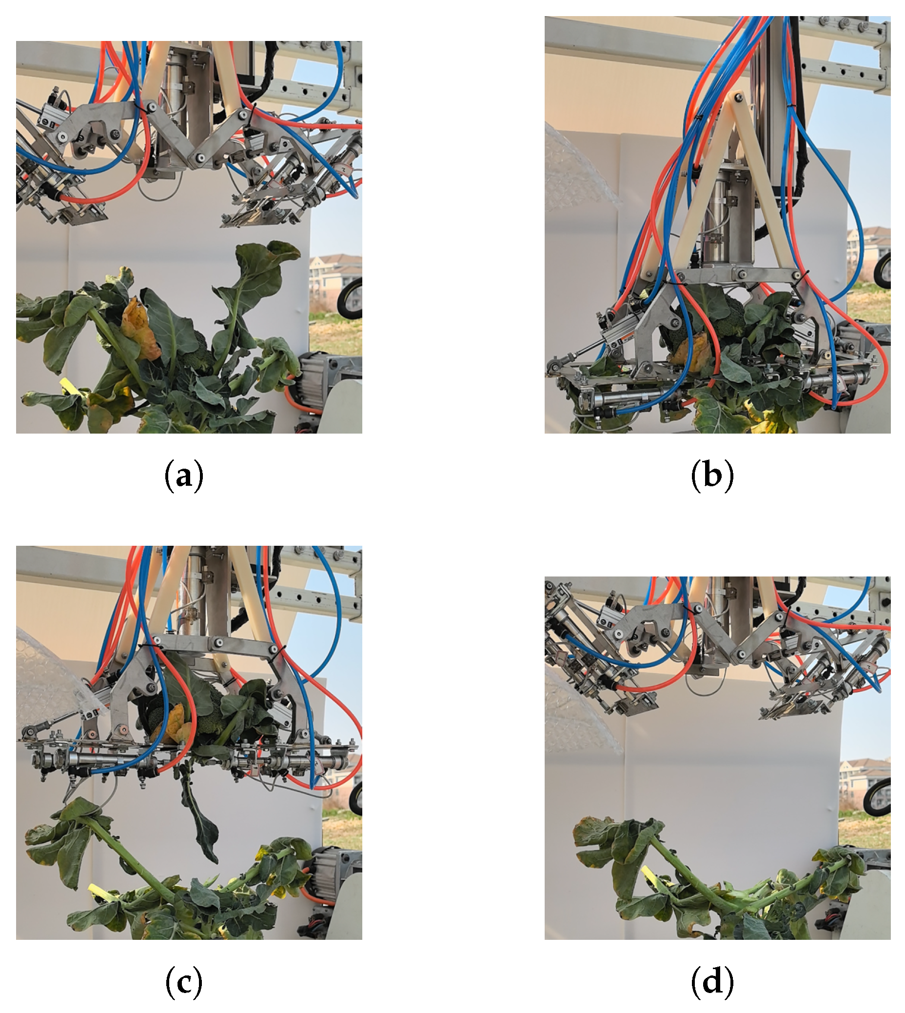
A performance comparison between the results of this study and those from other relevant studies is provided in
Table 9 to help readers gain a clearer understanding of this research. In the field performance testing of the end effector, both the operation and cutting success rates have exceeded 90%, verifying the feasibility and effectiveness of the overall design scheme. Compared with the conventional combination of a fixed cavity and a single-blade transverse cutting end effector [
17], the design featuring a mobile cavity with bilateral cutting demonstrates remarkable superiority in spatial utilization. With a substantial reduction in unilateral working space occupation, this configuration effectively mitigates interference risks during operation. In terms of grasping performance, the mobile cavity employs an encirclement-based principle to grasp broccoli florets, offering a more reliable and stable gripping effect compared with under-actuated grippers [
20]. From a cost-control perspective, the cutting approach utilizing mechanical blades driven by pneumatic cylinders exhibits greater economic efficiency than waterjet cutting technology [
18], which is resource-intensive, and complex flexible finger grasping solutions. The application of long-blade transverse cutting technology in the cutting structure design ensures that the cutting surface completely covers the bottom of the florets. This design significantly enhances the adaptability of the device to broccoli of various shapes, reducing the system’s reliance on high-precision positioning compared with anthropomorphic pinching–cutting structures [
22].
In terms of the precise positioning of the blade, the three posture control cylinders (push rod cylinder and position adjustment cylinders) achieve precise blade positioning through coordinated movements with precise timing. Specifically, first, the push rod cylinder’s piston rod extends, and the position adjustment cylinders’ piston rods fully retract, placing the end effector in an open state to lay the foundation for subsequent actions. After the Cartesian manipulators complete positioning (aligning the central axis of the end effector with that of the broccoli head), the push rod cylinder’s piston rod retracts, driving the connecting rod to rotate downward via the push rod. The position adjustment cylinders extend a few milliseconds later (preset in the program). Once all three cylinders are fully in place, the blades on both sides of the end effector are positioned on the same plane, and the end effector is in a fully grasping state, with the broccoli head enclosed in the “cavity” formed by the connecting rods, blade mounting planes, and the frame. It is worth noting that the hinge joints of the end effector use plastic sliding bearings from Igus, which can precisely control the relative positions of the hinges, ensuring smooth and gap-free movement—a key detail for achieving high-precision blade positioning.
Regarding robotic arm selection, Cartesian coordinate manipulators, owing to their structural characteristics, have significant advantages over multi-DOF robotic arms in terms of operational efficiency and cost control. The Cartesian manipulators used in this study, with 3 degrees of freedom (X, Y, and Z axes), consist of standardized components such as linear guides and synchronous belt modules, with fewer parts (about 1/3 to 1/2 of multi-DOF robotic arms), reducing manufacturing costs. In contrast, multi-DOF robotic arms (e.g., 6-DOF articulated arms) require high-precision harmonic drives, multi-axis controllers, and complex sensing systems, resulting in higher initial costs and more customized components. In structured planting environments (e.g., fixed row and plant spacing for broccoli), Cartesian harvesters are more efficient. Their trajectories are straight or fixed paths (e.g., “positioning-descending-cutting-ascending”), with simple path planning (no complex obstacle avoidance algorithms). In our field tests, the average harvest cycle per plant is approximately 7.0 s, which can be further optimized. Multi-DOF robotic arms, while adaptable to unstructured environments, require real-time obstacle avoidance and posture adjustment, leading to longer average harvest times (around 12.00 s as per related studies: Kang et al. [
22]). Cartesian manipulators are more convenient to maintain. Their core components (guides, motors) are less exposed, have modular structures, and clear failure points (e.g., insufficient guide lubrication, motor overheating), allowing field maintenance with simple tools. Multi-DOF robotic arms have highly integrated joints, sensors, and cables, making fault diagnosis complex (e.g., harmonic drive wear, multi-axis synchronization errors) and requiring professional technicians for maintenance, with faster component aging in dusty and humid field environments, leading to more frequent maintenance. In summary, Cartesian coordinate manipulators are better suited to the working requirements of the broccoli selective harvesting end effector, providing a technical guarantee for achieving efficient and cost-effective broccoli cutting operations.
However, the end effector still revealed multi-dimensional problems in the test process that need to be solved urgently. Significant variability exists in the retained length of the broccoli stem, showing a notable deviation from standardized market specifications. The surface quality of the stem section has not achieved the desired smoothness and flatness. Further resources should be invested in exploring optimal cutting parameters or integrating with other processes (such as conveying) for improvement. It is also worth noting that when the spacing between broccoli plants was excessively small (e.g., less than 300 mm), the end effector often encountered obstacles from surrounding stems, leaves, or other plants during the grasping process, leading to a reduction in operational success rates. Terrain undulations and weather conditions (such as varying light intensity) affected the recognition performance of the vision system, which in turn caused inaccuracies in the coordinate positioning of the Cartesian manipulator. This resulted in positioning deviations of the end effector beyond the allowable tolerance range, further influencing the success rates.


 ,
, 

