1. Introduction
Camellia oleifera is an evergreen woody plant with multiple uses, including as a food and medicinal resource, a raw material for light industry, and for soil and water conservation, as well as ecological and climate regulation. It is widely distributed in the red soil hilly regions of southern China and is also found in Southeast Asia and Japan [
1,
2,
3]. As the benefits of
C. oleifera oil become more widely recognized, its global promotion has increased, particularly in countries such as the United States and Australia [
4]. Currently,
C. oleifera cultivation in China covers approximately 70 million hectares [
5]. Traditionally, the fruit has been harvested manually, a method that is both time-consuming and costly, making it difficult to meet the demands of expanding plantation areas [
6,
7]. To achieve mechanized and automated harvesting, research into efficient harvesting equipment is essential.
In recent years, researchers have developed various
C. oleifera fruit harvesting devices to address challenges such as low manual harvesting efficiency, high labor costs, the short fruit maturation period, and the simultaneous presence of flowers and fruit. Delin Wu et al. designed a vibrating comb and a vibrating plate-type
C. oleifera fruit harvester, both of which prevent damage to branches, achieving a fruit drop rate of over 87.3% and a flower bud loss rate of less than 8.1% [
8,
9]. Du Xiaoqiang et al. developed a handheld, variable-spacing comb-type harvester that generates three types of drive during operation to facilitate fruit separation, achieving an average harvesting rate of 80% with minimal flower bud loss, thereby meeting operational requirements [
10,
11]. Honghui Rao et al. [
12] designed a multi-channel
C. oleifera fruit picking device with an adjustable picking head tilt angle. Controlled by a microcontroller, the picking mechanism effectively navigates branches based on the fruit growth trajectory, significantly reducing damage to flower buds and branches [
12].
Compared to the aforementioned
C. oleifera fruit harvesting devices, a newly developed tracked, diesel-powered harvester can achieve a harvesting efficiency of over 90% during the fruit maturation period, with a flower bud damage rate of less than 8%. Designed as a small agricultural vehicle for standardized
C. oleifera plantations in the red soil hilly regions of southern China, it can operate on slopes or terraced land with gradients of up to 30 degrees. Additionally, it features a compact design and a high degree of automation. To enhance the harvester’s functionality and off-road capability, and to enable multi-scenario automated harvesting, researchers have integrated a large number of sensors into the engine compartment. While this integration provides the harvester with remote control, fault detection, and real-time status evaluation, it has also led to a more compact component arrangement, causing airflow channels to become narrower and more dispersed [
13,
14]. As the heat generated by the components mixes with the air, the high-temperature air flowing over the complex surfaces of the parts experiences a significant reduction in flow velocity and sharp changes in direction. This can lead to vortex formation within the engine compartment, creating multiple localized temperature and airflow fields [
15,
16]. If the high-temperature air is not effectively expelled from the engine compartment in a timely manner, the temperature can remain above the acceptable range for extended periods. This can result in severe aging or damage to electrical circuits and sensors, leading to increased instrument display errors and delayed control responses [
17,
18]. Additionally, it can reduce the viscosity of the hydraulic oil in the hydraulic pump, causing a significant decrease in driving force and excitation force [
19].
In the field of agricultural vehicle research, studies focused on optimizing the internal structure of the engine compartment to address heat dissipation challenges are limited. İlhan Öztürk et al. [
20,
21] conducted 3D CFD analyses to achieve efficient engine compartment design from the perspective of engine operating temperatures, aiming to predict airflow patterns and associated heat transfer characteristics within a specialized agricultural tractor’s engine compartment. Through rational arrangement of various internal components—including the radiator, fan, cooler, filter, and battery bracket—they achieved optimized airflow paths and enhanced thermal dissipation performance. Their results demonstrated that CFD simulations can facilitate more efficient design solutions [
20,
21]. In complementary research, Nashir Umirov et al. [
22] investigated the influencing factors on thermal conditions in tractor and vehicle cooling systems during operation. They systematically elaborated the mathematical relationships required for establishing thermal balance equations in automotive and agricultural tractor engine cooling systems. By developing these thermal equilibrium models, the researchers established quantitative metrics for evaluating cooling system efficiency [
22].
However, in the domain of road vehicles, numerous researchers have made significant progress in addressing engine compartment heat dissipation issues, offering many feasible and efficient methods that hold substantial reference value. Chuanbo Liu et al. [
23] optimized the engine compartment structure of a passenger car using the SSA—RBFNN—NSGA-II method, improving heat dissipation performance. Experimental comparisons revealed that, in the optimal model, pressure loss was reduced by 14.781% compared to the original model, while temperature efficiency increased by 15.163%. The results confirmed that this method can be applied to multi-objective optimization of engine compartment heat dissipation performance and airflow resistance, providing a theoretical basis for the overall layout of the engine compartment [
23]. Zhaofeng Shi et al. [
24] proposed a combined one-dimensional (1D) and three-dimensional (3D) CFD simulation method to design a deflector structure that eliminates the issue of heat reflux, analyzing its heat dissipation performance. The combined simulation results showed that the ATO value of the cooling circuit was reduced by 2.5%, and the intercooler constant of the air conditioning circuit decreased by 12.1%, improving cooling performance. This provided a reliable reference for the development of engine compartment heat management systems in commercial vehicles [
24]. Jie Zhang et al. [
25] introduced a multi-objective optimization method for the heat management system of passenger vehicles, namely the “1D/3D collaborative simulation—PSO evaluation prediction model—simulation and environmental chamber experiment.” Final experimental results demonstrated that this method effectively reduced the surface temperature of the battery and the outlet water temperature of the engine by 9.6% and 5.9%, respectively, significantly lowering the heat risk for the vehicle [
25].
From the aforementioned studies, it is evident that CFD simulation has become an indispensable method in vehicle engine compartment heat management and structural optimization research. Additionally, intelligent optimization algorithms can be employed to further refine the results of CFD simulations. The Particle Swarm Optimization (PSO) algorithm is a population-based stochastic search algorithm, where parameters such as inertia weight and learning factors are typically fixed. The fixed inertia weight makes it challenging to achieve a good balance between the algorithm’s global and local search capabilities [
26,
27]. In this study, a collaborative optimization method combining CFD and APSO will be used for the first time to optimize the engine compartment structure of the
C. oleifera harvester. This approach aims to address the heat dissipation challenges of engine components, ensure long-term normal operation, and enhance its reliability.
2. Materials and Methods
The research follows a systematic technical approach comprising: “observation of failure phenomena”, “analysis of failure causes”, “optimization of internal component layout through iterative numerical simulations”, “structural optimization of the engine compartment cover using intelligent algorithms based on simulation results”, “construction of experimental platforms and formulation of test protocols”, “comparative analysis of experimental results”, “operational condition monitoring”, and “evaluation of optimization solutions”.
The harvester repeatedly exhibited severe performance degradation during operation, including diminished propulsion force, reduced vibration amplitude, decreased control system responsiveness, and overheating-induced shutdowns. Preliminary analysis confirmed that these operational failures were primarily caused by excessive temperature conditions within the engine compartment, where thermal levels critically determine the operational efficiency of both the cooling and hydraulic systems. Based on these findings, the following investigations were conducted:
(1) Establishment of a complete 3D model for CFD simulation analysis. In Fluent 2022R1 software, the engine, radiator, and hydraulic pump are designated as the primary heat sources. Boundary conditions, turbulence models, and computational parameters are determined. Through iterative calculations, the temperature and airflow distribution within the engine compartment are obtained. The temperature values and air velocity are used to preliminarily identify the blockage points in the airflow channels.
(2) To reduce research costs and accelerate the research process, without altering the overall dimensions, frame and chassis structure, or the models of components within the engine compartment, the spatial layout of internal components is continuously optimized based on multiple CFD simulation results. This aims to preliminarily clear the blockage points in the airflow channels and fundamentally improve the heat environment.
(3) The engine compartment cover possesses airflow-guiding functionality, and its structure significantly impacts the heat performance of the compartment. After determining the internal component layout, the engine compartment cover is redesigned to ultimately clear the blockage points in the airflow channels and substantially enhance the heat environment. The structural parameters of the engine compartment cover are defined within a specific range, and parameter variables are controlled. The structure of the engine compartment cover is modified multiple times by linearly increasing or decreasing the parameters. After each modification, CFD simulations are conducted, and temperature data at key locations of the cooling system and hydraulic system are recorded.
(4) A mathematical model is established to correlate the structural parameters of the engine compartment cover with the temperature field data. The optimization objective of achieving the lowest temperature is set, and the Adaptive Particle Swarm Optimization (APSO) algorithm is employed to search for the optimal solution within the model, which corresponds to the optimal structural parameters for the lowest temperature. Based on these optimal parameters, a 3D model of the engine compartment cover is created and integrated into the complete machine model for CFD simulation analysis. The results are compared with those from the pre-optimization simulations to observe changes in temperature distribution and air velocity.
3. Construction of the Heat Dissipation Model
3.1. Working Characteristics and Fault Analysis
3.1.1. Technical Specifications and Working Procedures
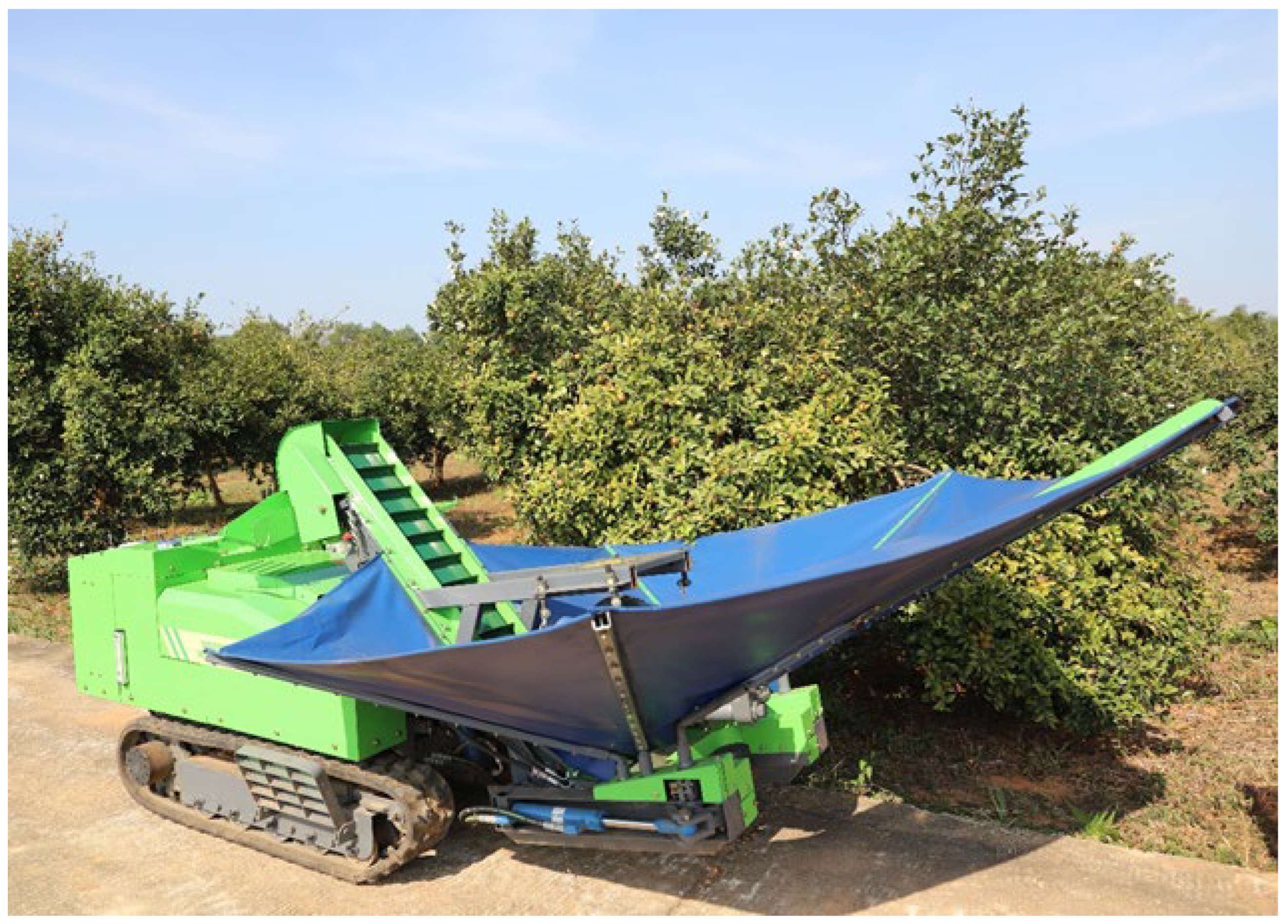
This study investigates a “4CLY-100”
Camellia oleifera harvester (
Figure 1), a specialized compact agricultural machine designed for standardized
C. oleifera plantations in the hilly red soil regions of southern China. The harvester features a hydraulic-powered chassis with a crawler-type walking mechanism, characterized by its compact structure and high maneuverability, which enables operation on slopes up to 30 degrees and terraced flatlands. Additionally, it incorporates a remote-control system for automated operation.
The diesel engine serves as the primary power source of the harvester. The internal hydraulic system is complex, with the hydraulic pump playing a crucial role in power conversion and transmission. Driven by the engine, the pump converts mechanical energy into hydraulic energy, delivering pressurized oil to various actuators at specified pressures. These actuators include the walking mechanism for machine movement, the clamping–vibration mechanism for fruit picking, and the collection mechanism for harvesting and sorting crops. During operation, the valve assembly precisely regulates the flow rate, direction, and on/off state of the hydraulic oil based on real-time harvesting requirements and control commands, ensuring coordinated operation of all actuators. The technical specifications of the harvester are presented in
Table 1.
The gear settings of the harvester’s transmission are determined based on travel direction and engine speed. Regarding travel direction, the transmission offers three modes: forward gear, reverse gear, and neutral gear. In terms of engine speed, the transmission provides two operational modes: low-speed gear and high-speed gear. In low-speed gear, the harvester achieves a linear travel speed of approximately 0.2 m per second, suitable for relocating to operational positions, precise positioning, and deploying the collection device. In high-speed gear, the linear travel speed reaches 0.5 m per second, primarily employed to increase the vibration frequency of the shaking mechanism and enhance fruit detachment efficiency.
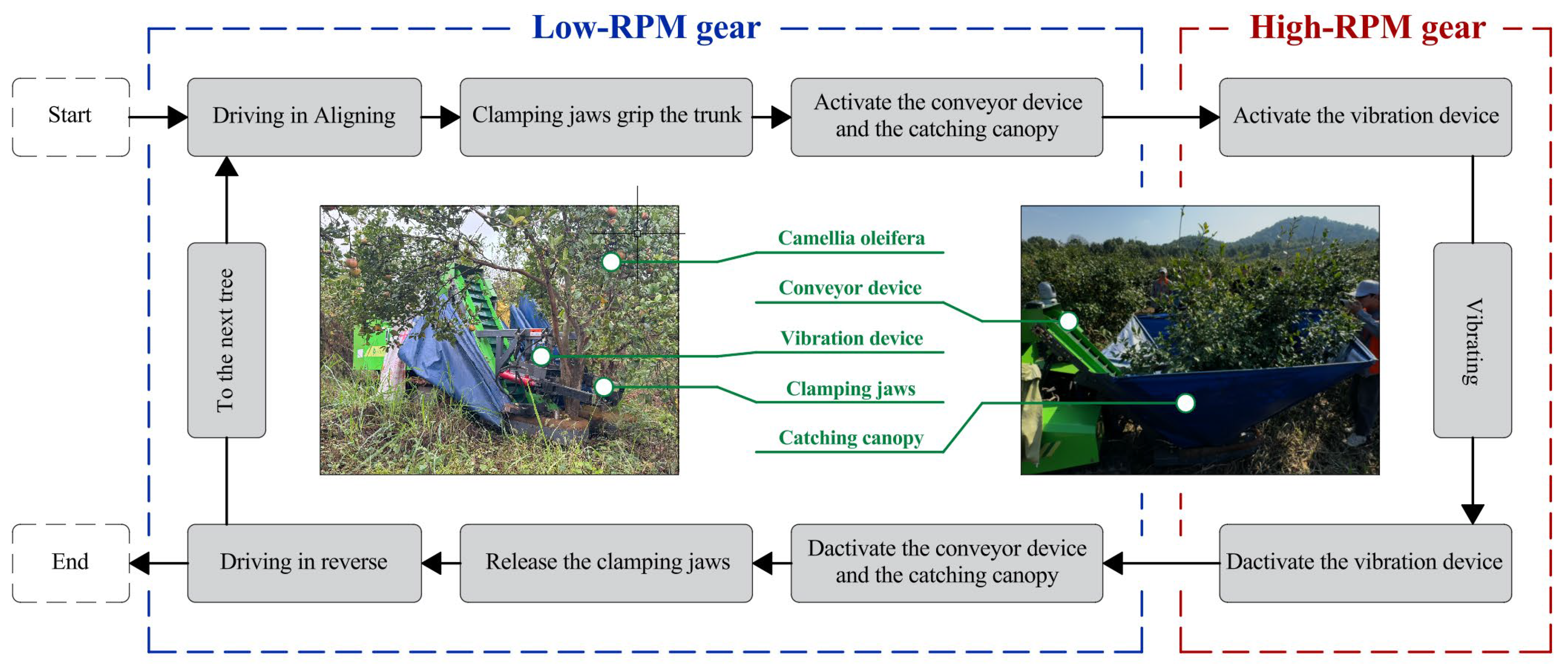
The workflow of the harvesting operation is illustrated in
Figure 2, with the specific implementation steps as follows: First, the operator selects low-speed gear to allow the harvester to approach the target
C. oleifera tree at a steady speed, followed by fine adjustments to ensure optimal contact between the clamping base and the tree trunk. The grippers are then closed to secure the trunk while simultaneously activating the conveyor belt and collection canopy. Upon completing these preparatory steps, the operator engages the shaking mechanism to initiate the harvesting process, during which real-time observation of fruit detachment is required. If a single vibration cycle (lasting no more than 3 s) fails to achieve sufficient fruit detachment, the shaking mechanism may be reactivated. However, to safeguard tree health, the total number of vibrations per tree is limited to two. Once most fruits have detached, the operator sequentially deactivates the shaking mechanism, conveyor belt, and collection canopy, releases the grippers, switches to reverse gear at low speed to withdraw from the current position, and finally proceeds to the next target tree. Historical operational data indicate that the standardized harvesting process for a single
C. oleifera tree requires approximately 1.2 to 1.4 min. This duration accounts for all operational phases, including positioning, clamping, vibration-based harvesting, and relocation.
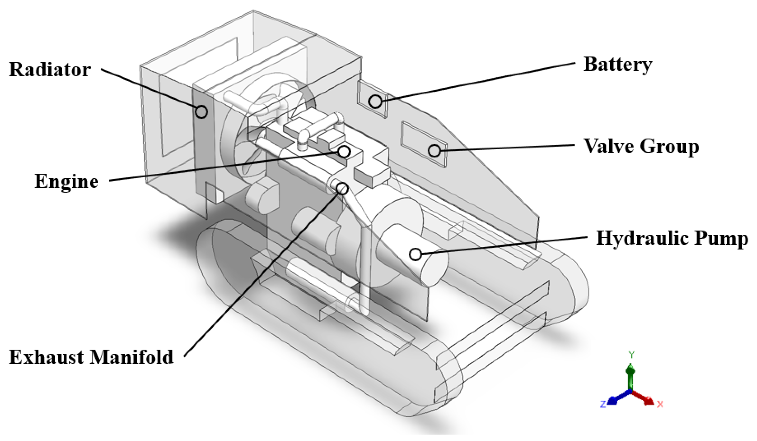
3.1.2. Cooling System and Hydraulic System
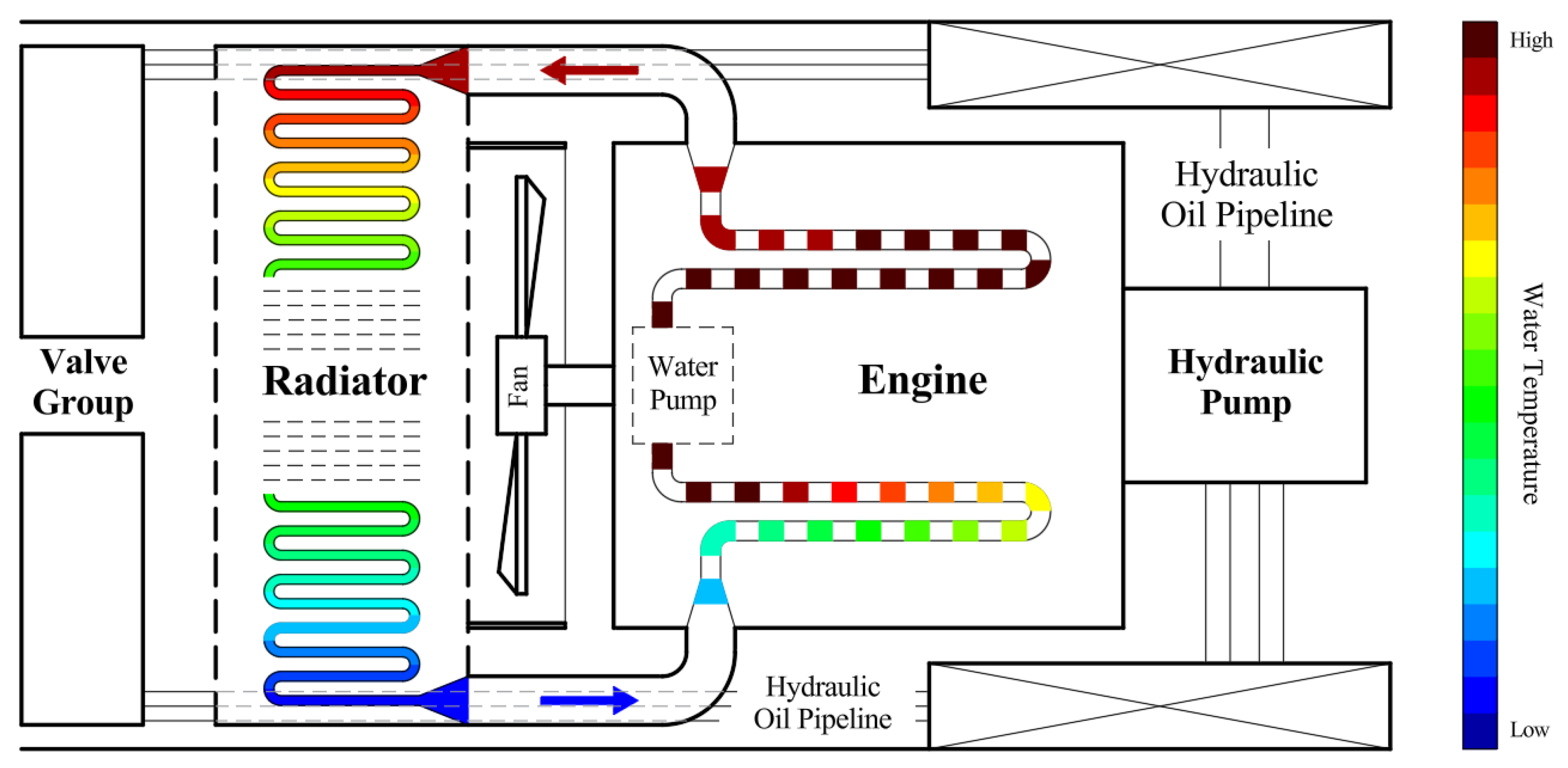
The cooling system and hydraulic system of the harvester engine compartment are illustrated in
Figure 3. The thermal management performance of the harvester engine compartment involves the coordinated operation of various functional components, with the cooling system serving as the core structure. Through the interconnected operation of key components including the fan, water pump, and radiator, the cooling system establishes a forced convection mechanism: the fan drives accelerated air exchange, the pump maintains coolant circulation, and the radiator enhances heat transfer efficiency by expanding the heat exchange surface area. In the
C. oleifera harvester, the spatial arrangement of these components directly influences airflow patterns, thereby determining the temperature distribution around the engine and the overall thermal environment within the engine compartment.
The harvester’s operational speed is significantly slower than that of construction vehicles, road vehicles, and large agricultural/forestry machinery, rendering the natural convection effects from external environments negligible in this study. Under optimal cooling system operation, the fan positioned between the engine and radiator not only significantly enhances the radiator’s cooling performance but also effectively exhausts the majority of heat generated by the engine surface, along with substantial heat dissipated from other components such as the hydraulic system and electronic devices, achieving ideal forced convection cooling. The fan facilitates rapid air movement, enabling efficient heat transfer through airflow, thereby ensuring stable operation of internal components within appropriate temperature ranges while preventing performance degradation, operational failures, and premature aging caused by overheating.
As the core component of the hydraulic system and the power transmission hub of the entire machine, the hydraulic pump is surrounded by densely arranged and complex hydraulic tubing. These tubes connect the hydraulic pump, valve assembly, and various actuators. To optimize the limited engine compartment space while maintaining a balanced overall layout, most hydraulic tubes are bundled along both sides of the engine. This configuration offers structural strength and installation convenience advantages, providing relatively stable mounting foundations for the hydraulic tubing system.
3.1.3. Problem Definition and Fault Analysis
In the mechanized harvesting operations within China’s primary C. oleifera production regions (including typical terrains such as hilly areas and terraced flatlands), field observations have identified four predominant failure modes that significantly compromise operational efficiency and harvesting quality:
Propulsion Degradation: Manifested as reduced obstacle-crossing capability, increased turning radius, and insufficient climbing power, necessitating frequent route deviations (detouring to flat areas) for harvesting operations, which substantially prolongs working duration.
Vibration Force Attenuation: Characterized by decreased frequency and increased amplitude of the shaking mechanism, resulting in elevated bark/root damage rates, exacerbated soil disturbance, and notably reduced fruit detachment efficiency.
Control System Response Lag: Exhibited as prolonged actuator response time following remote commands, leading to compromised clamping accuracy between grippers and tree trunks, and consequent extension of overall harvesting time.
Overheating Shutdown: Distinguished by abrupt machine halt with engine auto-stop, followed by power supply alarm and automatic cutoff. This condition presents rollover risks during slope operations and may induce slippage in humid environments, jeopardizing operational safety.
Preliminary analysis indicates these failures primarily stem from deteriorated engine compartment thermal management performance, specifically:
(1) Hydraulic System Thermal Load Accumulation: The hydraulic pump’s direct connection to the engine via transmission makes its operating temperature highly engine-dependent. The longitudinal layout of hydraulic lines along both engine compartment sides features extended paths with multiple bends, positioned adjacent to high-temperature components like the engine and exhaust manifold. This configuration increases hydraulic flow resistance and creates localized heat accumulation. Sustained high temperatures reduce hydraulic oil viscosity, and when such low-viscosity oil enters actuators, it fails to deliver adequate hydraulic pressure, ultimately causing propulsion and vibration force degradation [
28].
(2) Disordered Airflow Organization in Cooling System: The valve assembly’s proximity to the radiator air intake, combined with dense obstructions from electrical wiring, piping, and non-metallic components, severely blocks ventilation channels. This arrangement not only impedes coolant cooling but also disrupts forced convection effectiveness. When high-temperature airflow passes complex component surfaces, its velocity decreases with chaotic flow directions, prone to forming localized airflow/temperature fields that critically impair cooling performance. Furthermore, prolonged high-temperature exposure accelerates aging of valves, electrical components, and non-metallic parts, creating potential safety hazards [
29].
3.2. Construction of Computational Fluid Dynamics Simulation Model
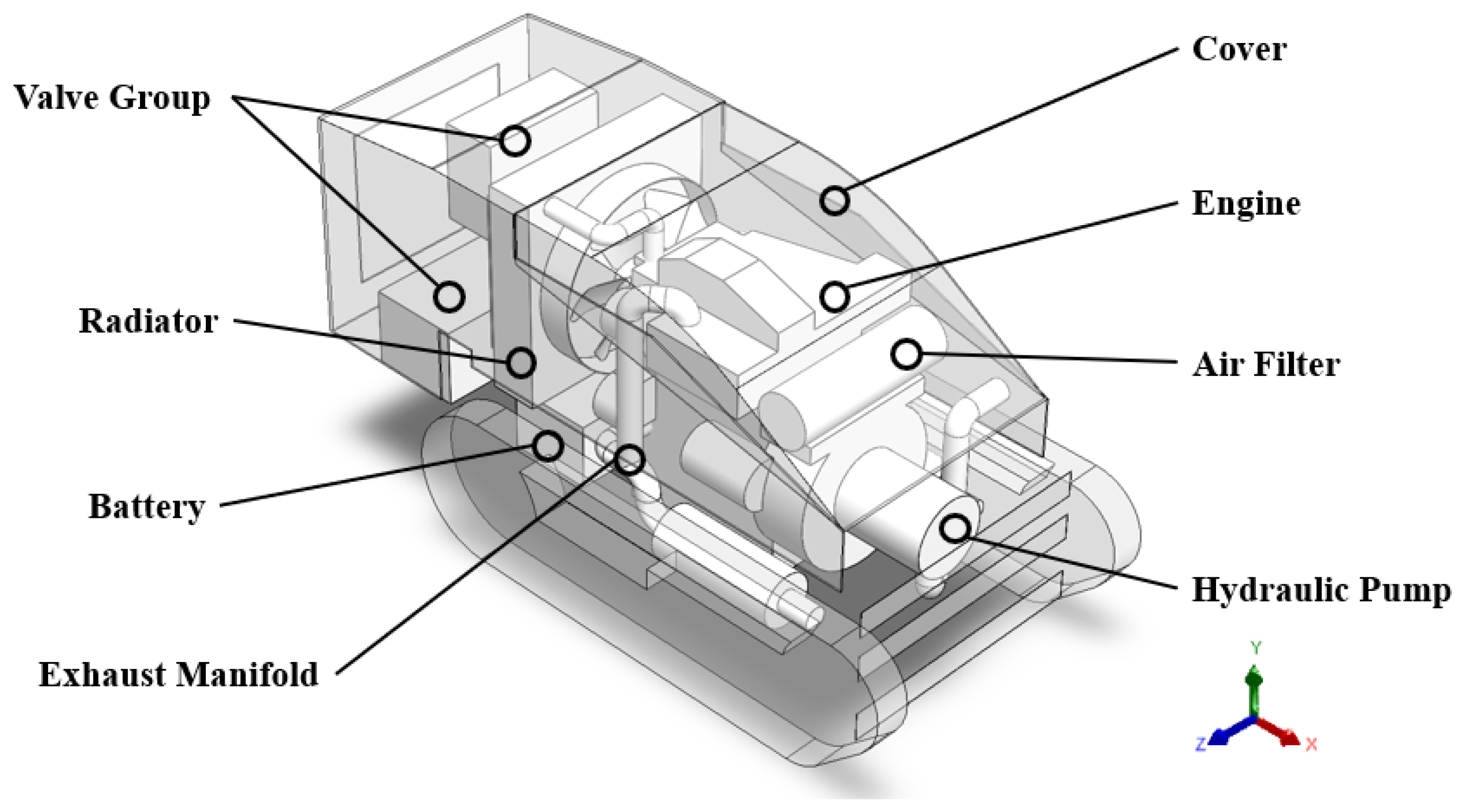
Model simplification plays a crucial role in computational fluid dynamics (CFD) analysis. As illustrated in
Figure 4, the harvester model was developed using SolidWorks2022 software with appropriate simplifications. The computational model comprises primary components and their auxiliary parts located within the engine compartment. To optimize computational efficiency, all external components (including harvesting mechanisms and fuel tanks) were excluded from the simulation, while retaining only the essential features enclosed by the compartment walls.
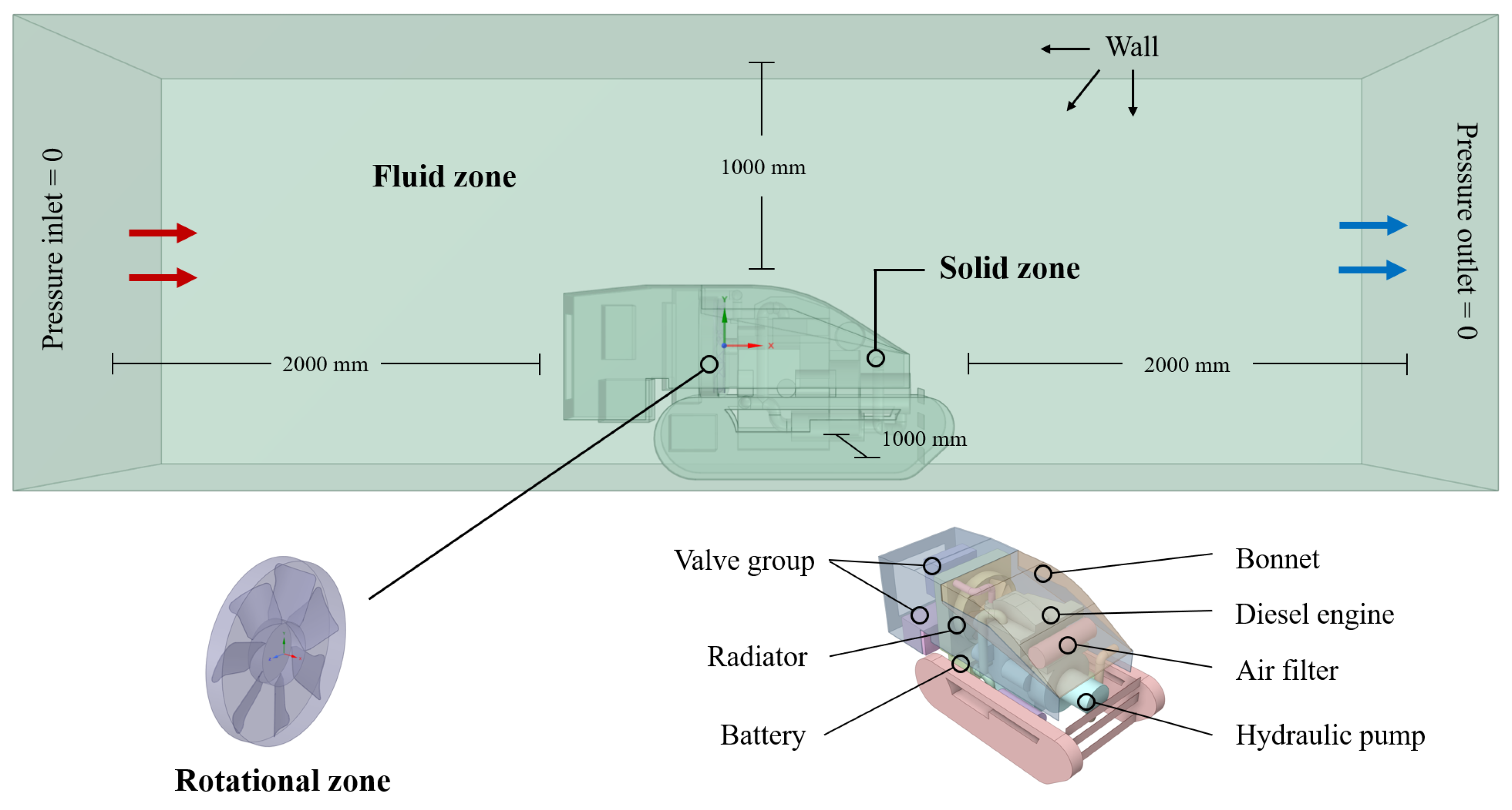
The rationality of the boundary condition settings determines the convergence and calculation accuracy of the results [
30,
31]. As shown in
Figure 5, the simplified 3D model was processed using SpaceClaim 2022R1 software to create both solid and fluid domains. A confined space was established where all entities enclosed within the space boundaries were defined as the solid domain. The fluid domain was subsequently obtained through Boolean subtraction of the solid domain components. To facilitate simulation visualization, the fan was specifically designated as a rotating domain. Given the negligible influence of natural convection, both the pressure inlet and outlet were set to zero pressure values.
The quality of the mesh significantly impacts both computational accuracy and efficiency [
32]. In the Meshing module of Fluent 2022R1 software, an unstructured tetrahedral patch conforming method was used to generate the mesh, which consists of approximately 242,000 nodes and 2.27 million volume elements. The fluid domain mesh element size is no larger than 0.05 m, and the rotating domain element size is no larger than 0.02 m, with automatic curvature capture of the model. The mesh does not contain negative volume elements, and its quality meets the computational requirements. To correctly define the computational domain in the Solution module, a set of pressure inlet and outlet boundaries were set, with the pressure value set to 0, not affecting the forced convection effect. In the Solution module, energy units were enabled, assuming a uniform surface temperature distribution, with the engine, radiator, hydraulic pump, and exhaust manifold treated as heat sources. The rotating direction, speed, and axis of the fan were controlled using the Moving Reference Frame (MRF) method [
33]. The influence of natural convection was neglected within the engine compartment, maintaining a constant air density. The fluid–structure coupling method was set to “Coupled”.
The turbulence model serves as an essential requirement for achieving closure of the flow control equations. The Reynolds-Averaged Navier–Stokes (RANS)-based turbulence models have gained widespread recognition for their demonstrated advantages in engineering flow simulations [
34]. However, the adaptive advantages of turbulence models are typically limited to specific operating conditions. Through extensive testing, it has been determined that the realizable k–ε model can effectively simulate the thermal environment within the
C. oleifera harvester’s engine compartment. Therefore, in this study, the realizable k–ε model has been selected as the turbulence model of choice.
In the Fluent 2022R1 software computational setup, the energy equation was activated. To enhance computational visualization, only the engine, radiator, and hydraulic pump were considered as heat sources in this study. Although this simplification introduces significant deviations from actual conditions, it effectively demonstrates the temperature variations in both the cooling system and hydraulic system, thereby improving feedback efficiency.
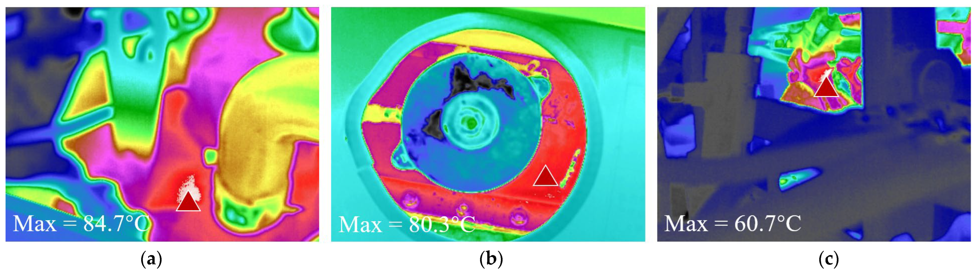
Surface temperatures of these three components for the computational setup were preliminarily obtained through infrared thermography. The study employed a “Fortic236” thermal imager produced by Fortic Smart Technology (Shanghai) Co., Ltd. (Shanghai, China) to measure surface temperatures of these components during harvester overheating shutdown incidents (
Figure 6).
Based on surface temperature measurements, the highest temperature points from each component were incorporated into the computational setup. Assuming uniform temperature distribution, the solid domain parameters in Fluent 2022R1 were configured as follows: engine at 84.7 °C, radiator at 80.3 °C, and hydraulic pump at 60.7 °C.
3.3. Construction of the Mathematical Model of Adaptive Particle Swarm Optimization
The engine compartment cover serves multiple critical functions in the integrated system, including waterproofing and noise reduction, while its aerodynamic characteristics particularly influence the compartment’s thermal management performance [
35,
36]. Consequently, structural optimization of the engine compartment cover is essential. Given its advantages of low manufacturing cost, lightweight properties, and adjustable three-dimensional configuration, this study employs the Adaptive Particle Swarm Optimization (APSO) algorithm to identify the optimal solution for the objective function—determining the structural parameter combination that minimizes engine compartment temperature while ensuring effective cooling performance.
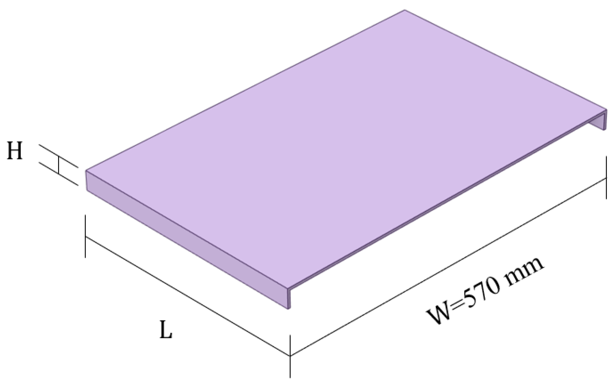
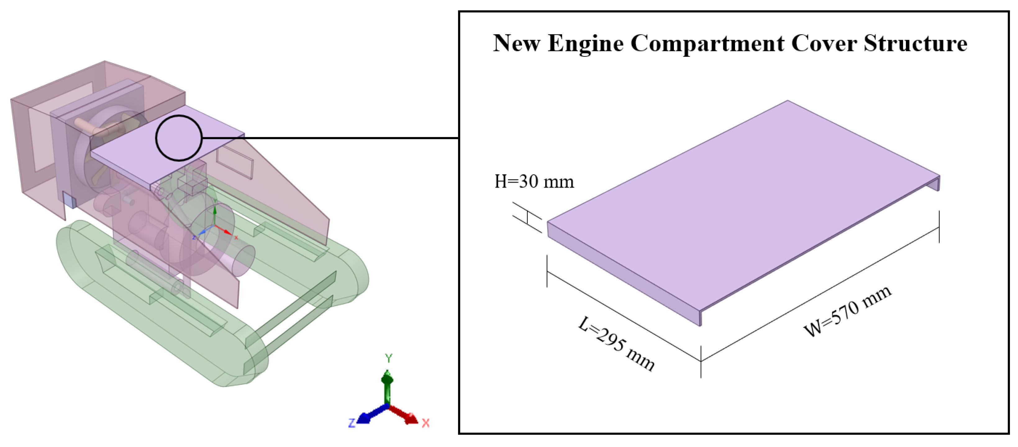
Due to the control of the structural optimization cost of the harvester, the width of the engine hood remains unchanged. As illustrated in
Figure 7, with the engine compartment cover width (W) fixed at 570 mm, the optimization focuses on two key variables: the cover length (L) and height (H). Systematic adjustment of these parameters enables further enhancement of the compartment’s thermal dissipation capability.
For the length (L) and height (H) of the engine hood, the given constraints are:
The dependent variables are the surface temperature of the hydraulic oil pipeline T
1 and the hydraulic pump T
2 in the hydraulic system. The objective is to achieve T
min, and the optimization objective function is:
In the formula, both T1 and T2 are the results of CFD simulations.
This study employs polynomial regression to construct a surrogate model for optimizing experimental data and establishing mapping relationships between parameters. This method is particularly suitable for low-dimensional datasets and can effectively characterize simple nonlinear relationships, offering advantages in computational efficiency and strong model interpretability. The surrogate model development process involves the following key steps: first, data preprocessing is performed on independent variables (L, H) and the dependent variable T (where T = (T1 + T2)/2). Subsequently, the dataset is partitioned into training (80%) and testing (20%) subsets. Polynomial feature generation and linear regression training are conducted, with regularization techniques applied to prevent overfitting. Model performance is evaluated using RMSE and R2 metrics, while optimal polynomial degree determination incorporates cross-validation. Finally, model validation is performed through “actual vs. predicted” plots and residual analysis, with the optimized model serving as the fitness function for the APSO algorithm.
4. Optimization of Heat Dissipation Performance
4.1. Analysis of Engine Compartment Heat Dissipation Environment
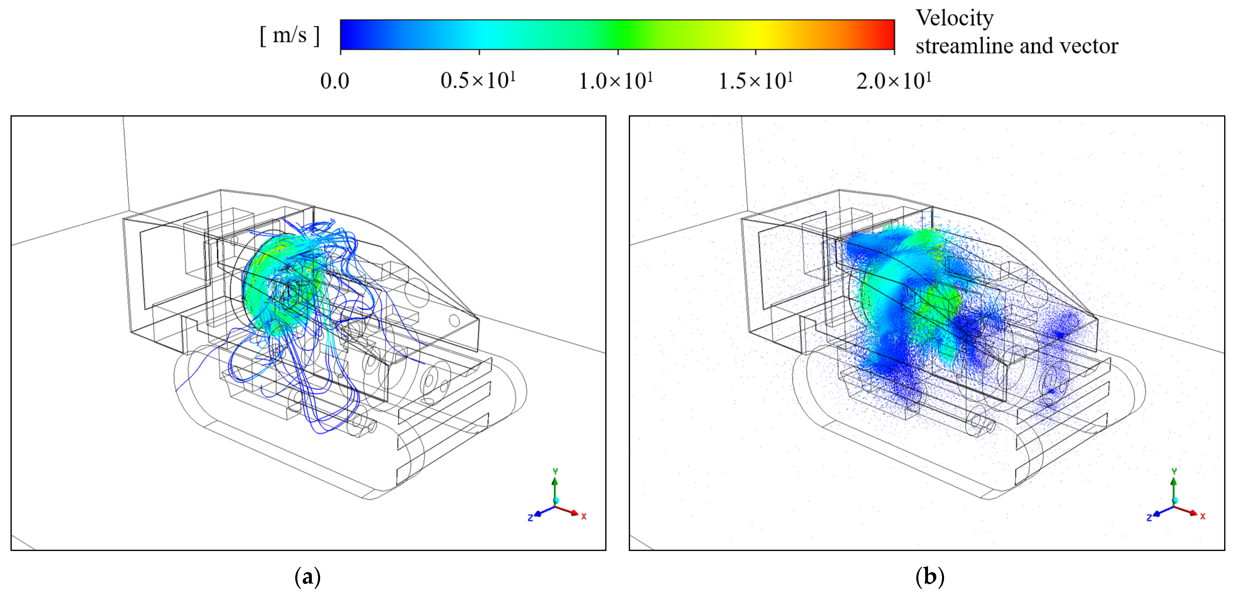
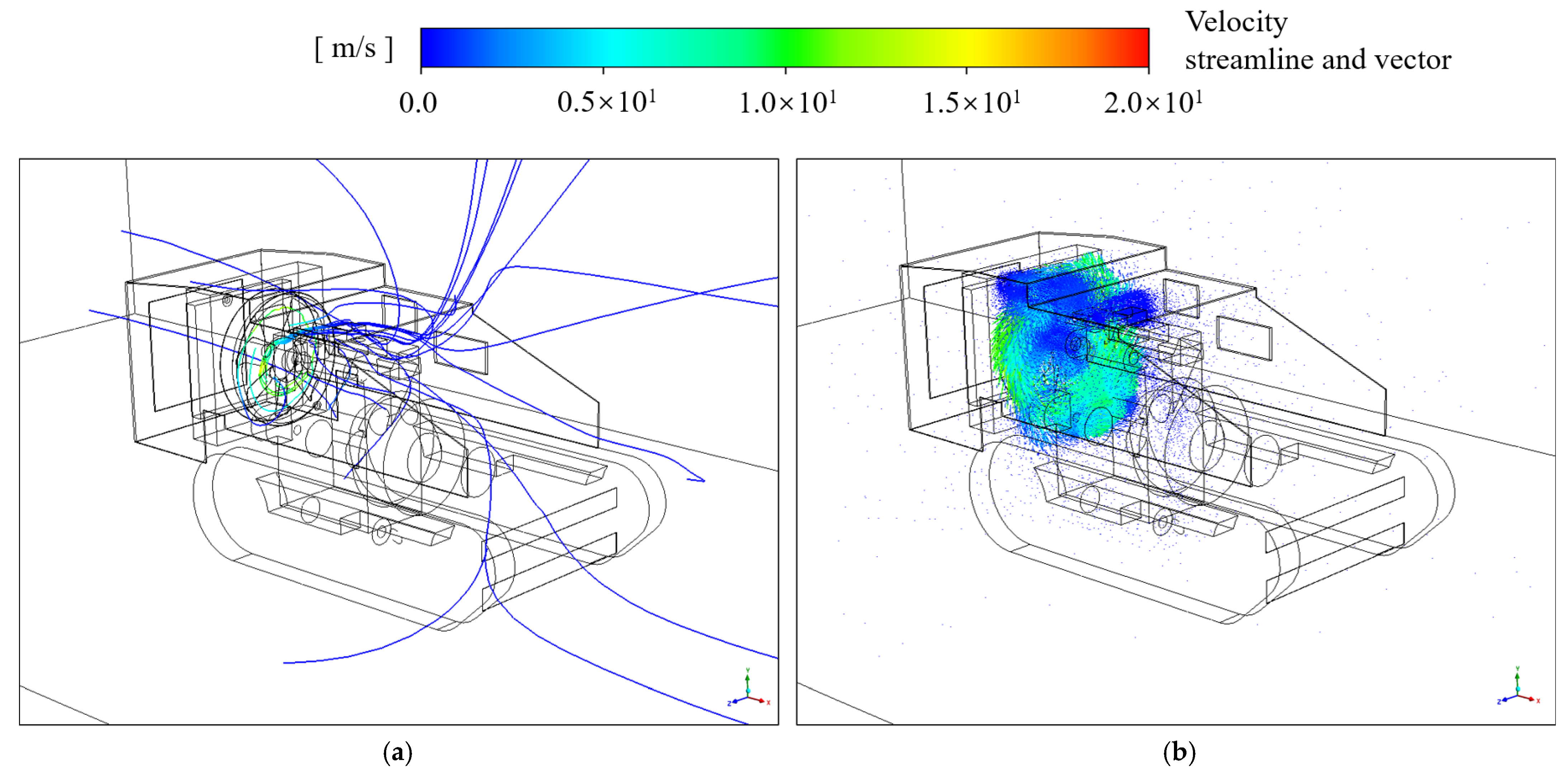
The simulation results of the airflow field within the harvester engine compartment are presented in
Figure 8. Analysis of both velocity trajectory lines and vector fields reveals significant flow obstruction phenomena in the engine compartment’s internal airflow distribution. The engine’s top and side regions exhibit sparse trajectory lines with minimal unidirectional flow, indicating poor airflow organization in these areas. When high-velocity airflow passes complex component surfaces, its speed decreases substantially while generating extensive recirculation zones, resulting in hot gas re-entrainment.
Velocity vector field analysis further demonstrates numerous low-speed vortex regions concentrated primarily around heat-generating components and the hydraulic system. The simulation results confirm severe obstruction of internal flow channels in the current engine compartment configuration, coupled with ineffective airflow guidance from the engine compartment cover structure. These factors collectively produce widespread low-velocity zones that critically impair cooling efficiency.
This flow characteristic analysis identifies two fundamental issues in engine compartment airflow organization: dispersed and constricted flow channels caused by geometric layout, and degraded thermal performance due to inadequate airflow guidance structures. Their synergistic effects create unfavorable airflow patterns for heat dissipation, necessitating urgent optimization of component arrangement and improved flow guidance design to enhance overall flow performance.
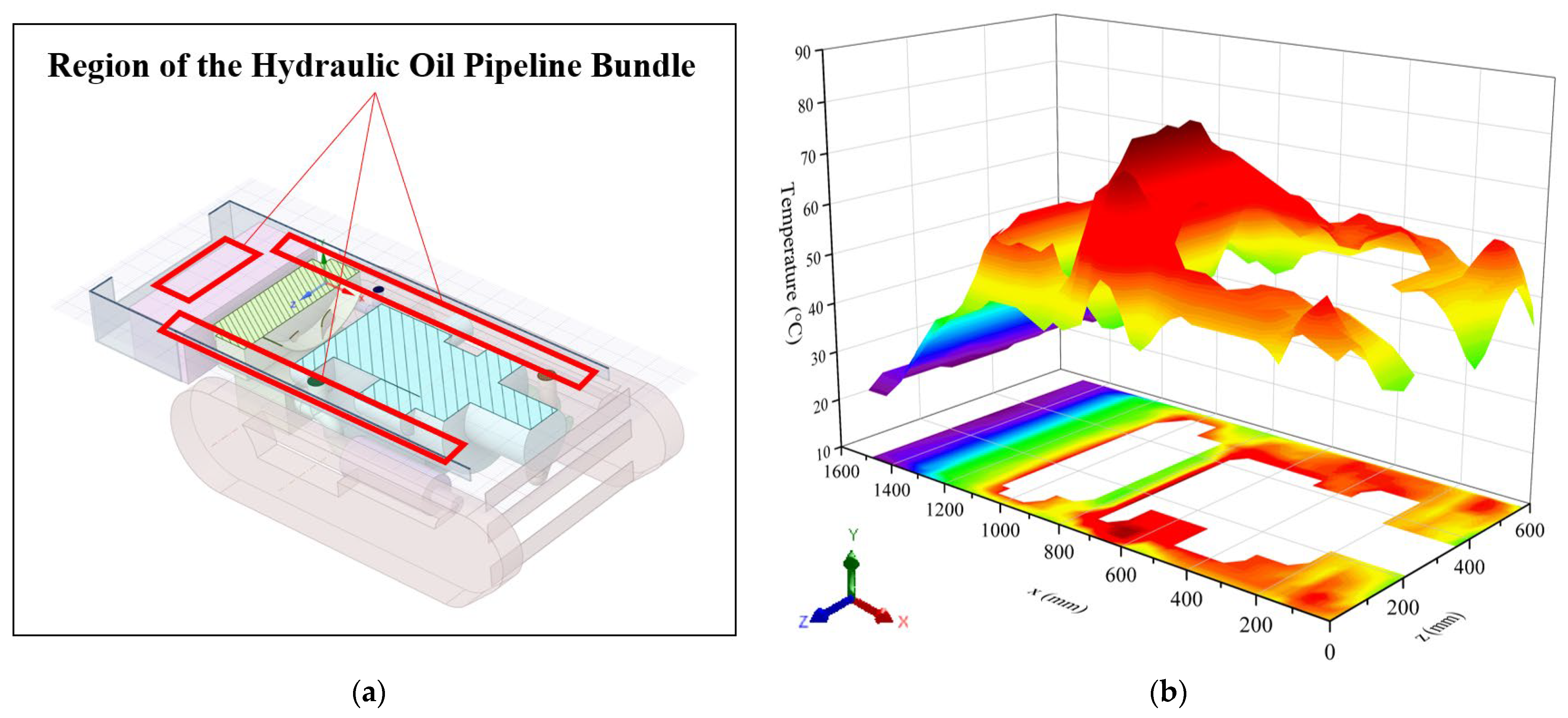
In Fluent 2022R1 software, 3D computational results often suffer from component occlusion and localized detail blurring during visualization. To clearly demonstrate the temperature distribution characteristics of the hydraulic system, this study employed SpaceClaim 2022R1 software to perform section cutting on the densely arranged hydraulic tubing area described in
Section 3.1.2. A cross-section parallel to the x–z coordinate plane was generated at this location, and the corresponding temperature contour map was plotted using Origin 2024 software (
Figure 9).
The simulation results reveal significant temperature non-uniformity within the engine compartment, particularly in the following regions: the gap between the engine and fan, both sides of the engine, and areas adjacent to the exhaust manifold, where temperatures are consistently elevated. Analysis of the hydraulic tubing layout indicates that the current pipeline system originates from the front-mounted hydraulic pump, extends through multiple bends, and terminates at the rear valve assembly. This configuration exhibits two notable characteristics: the circuitous routing of the tubing, and its traversal through multiple high-temperature zones. Such a design implies that during continuous harvester operation, the surrounding thermal environment will persistently exchange heat with the hydraulic oil, inevitably leading to temperature rise.
This phenomenon highlights two critical issues in the current hydraulic system design: the excessive length of tubing increases the contact area between hydraulic oil and high-temperature surroundings, and the routing through multiple heat-intensive zones exacerbates thermal conduction effects. These combined factors substantially compromise the operational stability of the hydraulic system, necessitating optimization of the tubing layout for improved performance.
4.2. Optimization of Spatial Layout of Key Components in the Compartment
Under the cost optimization objective and within the constraints of maintaining overall dimensions and key component specifications, an optimized engine compartment layout design was developed.
Figure 10 presents the simplified optimized engine compartment model, which achieves two primary improvements compared to the original layout (
Figure 4). First, by minimizing obstructions around the radiator to ensure an unobstructed air intake side while preserving adequate airflow paths on the exhaust side, favorable conditions for efficient cooling are created. Second, by rerouting hydraulic lines away from heat sources and concentrating them in well-ventilated areas, abnormal hydraulic oil temperature rise is effectively prevented. The specific optimization measures include:
(1) Cooling System Optimization: To enhance forced convection effectiveness, the valve assembly originally positioned behind the radiator (negative x-direction) was relocated to the side panel using a flush-mounted design integrated into the engine compartment wall. (Note: The simplified model only shows main structures; some components like the valve assembly are actually installed at the engine compartment shoulder area, represented by thin-wall features.) This modification completely eliminates intake-side obstructions for the radiator.
(2) Battery Relocation: The battery was moved from beneath the radiator to a position parallel with the valve assembly in the x–y plane. This change both removes airflow blockage below the radiator (increasing effective airflow cross-section) and prevents battery overheating risks from proximity to heat sources. The new layout significantly reduces battery-induced airflow interference while improving space utilization near the engine.
(3) Air Filter Externalization: The originally internal air filter was repositioned outside the engine compartment. This adjustment substantially increases available airflow space above the hydraulic pump (positive y-direction), providing better routing conditions for hydraulic lines and electrical wiring.
(4) Hydraulic System Rerouting: Hydraulic pipes and electrical circuits were redesigned from their original positions along the engine compartment sides and behind the radiator to a consolidated area above the hydraulic pump. This new arrangement keeps lines distant from major heat sources while placing them in well-ventilated zones, enhancing thermal stability.
(5) Exhaust System Modification: The original dual-outlet exhaust was simplified to a single-outlet configuration, with the exhaust manifold reoriented from downward-vertical to forward-downward positioning. This improvement not only streamlines the exhaust system (reducing backpressure) but also achieves complete airflow continuity along both engine sides, minimizing localized vortex generation.
4.3. Optimization of Engine Compartment Cover Structure
4.3.1. Preprocessing of Simulation Data
The engine compartment cover, as a critical functional component, integrates multiple functions including waterproof sealing, airflow guidance, and noise suppression, with its structural design significantly influencing the engine compartment’s thermal performance. Building upon the parametric 3D model of the engine compartment cover established in
Section 3.2 and the optimized layout of key internal components, this study employs a combined approach of numerical simulation and intelligent algorithms to optimize the engine compartment cover structure.
Initially, a controlled variable methodology was applied for CFD simulations of the engine compartment cover’s structural parameters. Maintaining identical boundary conditions, meshing strategies, and computational parameter settings as described in
Section 3.3, linear adjustments were performed on two critical design parameters (L and H) within their respective value ranges:
A total of 420 independent simulation cases (α_max × β_max) were completed. Each simulation recorded two key performance indicators: hydraulic pump surface temperature (T1) and temperature in the densely packed hydraulic tubing area (T2), serving as evaluation metrics for cooling performance under different parameter combinations.
Figure 11 presents simulated temperature field results across different structural parameter combinations, with the temperature metric being the sum of temperature rises at the hydraulic pump (T
1) and hydraulic tubing cluster (T
2). The results indicate that the lowest temperature zone (dark blue region in the figure) corresponds to the optimal dimensional combination. However, due to limited CFD sampling points, precise determination of optimal parameters requires establishing an objective optimization function based on existing simulation data, followed by precise optimization using the APSO algorithm.
4.3.2. Construction of Proxy Model
The computational parameters for the surrogate model are detailed in
Table 2. The modeling process begins with standardized preprocessing (Z-score method) of the height, length, and temperature data, followed by cross-validation to select the optimal polynomial degree (1st–3rd order) while outputting the corresponding root mean square error (RMSE) for each candidate. Upon model training completion, predictive performance is evaluated on the test set using quantitative metrics including RMSE and coefficient of determination (R
2). Reliability verification includes parallel generation of actual vs. predicted comparison plots and residual distribution plots. The finalized surrogate model is saved as the fitness evaluation function for subsequent APSO optimization.
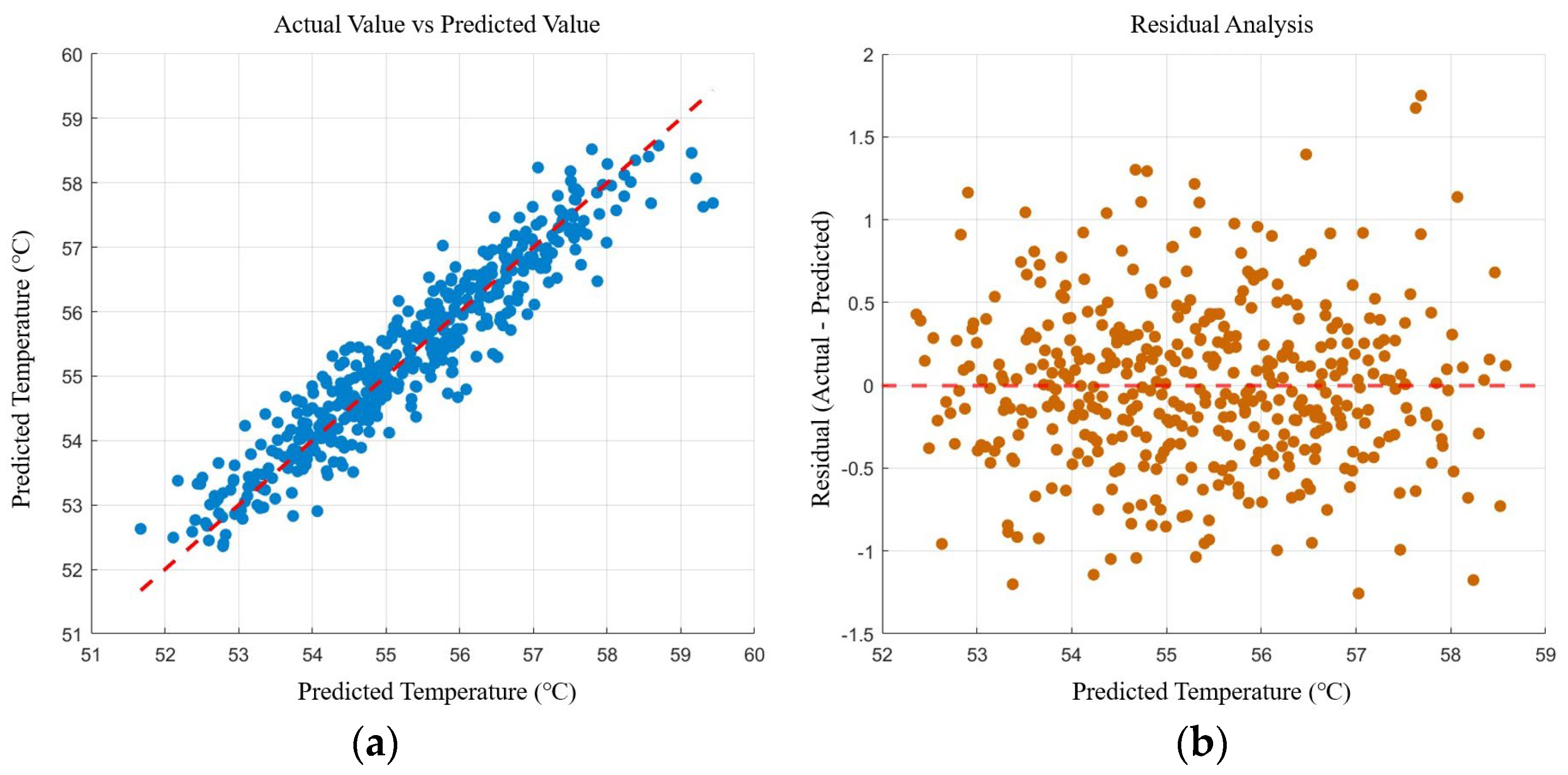
A polynomial regression-based temperature prediction model was developed and systematically evaluated through visualization methods. As shown in
Figure 12a, actual and predicted values demonstrate strong alignment, with data points closely distributed along the reference line (y = x). The model achieves R
2 > 0.95 and RMSE ≈ 0.12 °C, indicating that this second-order polynomial regression explains over 95% of temperature variation while meeting engineering accuracy requirements.
Residual analysis in
Figure 12b reveals randomly distributed prediction errors with near-zero mean and standard deviation
≈ 0.12 °C. This confirms the absence of systematic bias and demonstrates limited error fluctuation. Combined visualization analyses verify the surrogate model’s excellent predictive capability and stability for engine compartment structural parameter optimization.
4.3.3. Implementation of Algorithm-Based Optimization Search
Based on the established surrogate model, this study implemented the computational workflow of the APSO optimization algorithm on the MATLAB R2024b platform. As detailed in
Table 3, all critical parameters required for algorithm execution were rigorously configured, adhering to fundamental principles of intelligent optimization algorithms while specifically accommodating the unique requirements of this research problem.
The parameter optimization results using the Adaptive Particle Swarm Optimization (APSO) algorithm demonstrate that the system achieves the minimum temperature of 49.2 °C under the parameter combination of length = 295.3 mm and height = 30.2 mm within the defined design space. This optimized solution outperforms the lowest temperature record in the original dataset, validating the algorithm’s effective search capability in continuous parameter space. The APSO computational results are presented in
Figure 13. The position where the optimal solution occurs is marked by a five-pointed star in
Figure 13a.
Analysis of the particle distribution thermodynamic diagram (
Figure 13a) and fitness convergence curve (
Figure 13b) reveals that the APSO algorithm maintains an effective balance between global exploration and local exploitation during optimization. The results exhibit two key characteristics. First, the final optimal solution resides in a low-temperature concentration region of the parameter space, showing strong consistency with the temperature variation trend in the original data. Second, the fitness value stabilizes after approximately 60 iterations, confirming the rationality of both the algorithm parameter settings and surrogate model construction. The proposed optimization methodology provides reliable theoretical guidance for structural parameter design, and the optimal parameter combination is recommended for further simulation and experimental validation in practical engineering applications.
Considering manufacturing requirements and cost control, the optimized dimensions were rounded to length = 295 mm and height = 30 mm. As shown in
Figure 14, the refined engine compartment cover model was integrated with the improved compartment assembly in SpaceClaim 2022R1 3D modeling software. Subsequent CFD simulations were conducted to verify thermal performance, and the design will be finalized for experimental validation if simulation results meet predefined optimization targets.
4.4. Simulation Verification
Figure 15 presents the optimized airflow field simulation results. Compared with the initial design (
Figure 8), the optimized solution demonstrates the following significant improvements. First, the increased density of airflow trajectory lines exiting the compartment indicates enhanced airflow organization. Second, internal recirculation phenomena have been effectively suppressed, with substantial mitigation of flow separation issues. Notably, no significant local vortex zones are observed around the hydraulic system, while the engine compartment cover’s airflow guidance function has been fully utilized, ensuring all densely arranged hydraulic tubes remain within effective airflow coverage.
The simulation results confirm that the optimized design has fundamentally resolved the internal airflow obstruction issues, achieving significant improvement in the forced convection system’s cooling efficiency.
The simulation results further reveal that the optimized routing of hydraulic tubing bundles directly influences temperature field characteristics. As shown in
Figure 16, the temperature contour plot at the optimized cross-section demonstrates substantially reduced temperature gradients around the hydraulic system, with heat source distribution exhibiting more regular linear patterns. Compared with the pre-optimization condition (
Figure 9), the total length of hydraulic tubing has been noticeably shortened with fewer bends, significantly reducing thermal impact from high-temperature sources in densely packed areas.
The temperature field improvements corroborate the airflow simulation results, jointly verifying enhanced performance of the compartment’s forced convection system. The optimized thermal patterns further validate the positive effects of layout optimization on heat dissipation performance.
5. Experimental Verification
5.1. Experimental Preparation and Scheme Design
This study employs a comparative experimental approach to validate the effectiveness of the optimized engine compartment design, evaluating surface temperature variations of key components under typical operating conditions before and after optimization, combined with empirical observations. The experiment was conducted at a
Camellia oleifera plantation in the Shanxia Experimental Forest Farm, Fenyi, Jiangxi Province, China (
Figure 17), which features representative operational environments that accurately reflect the harvester’s actual working conditions. The testing period coincided with the
C. oleifera fruit ripening season, with the experimental protocol strictly adhering to engineering validation standards. The experiment was conducted in October 2024.
Environmental parameters during testing are detailed in
Table 4, with meteorological and topographic data provided by professional technicians from the forest farm’s monitoring station. Field investigations confirmed that the selected site fully meets experimental requirements, ensuring data validity and reliability. The site’s climatic characteristics demonstrate strong consistency with the harvester’s typical operating environment, providing representative conditions for optimization validation.
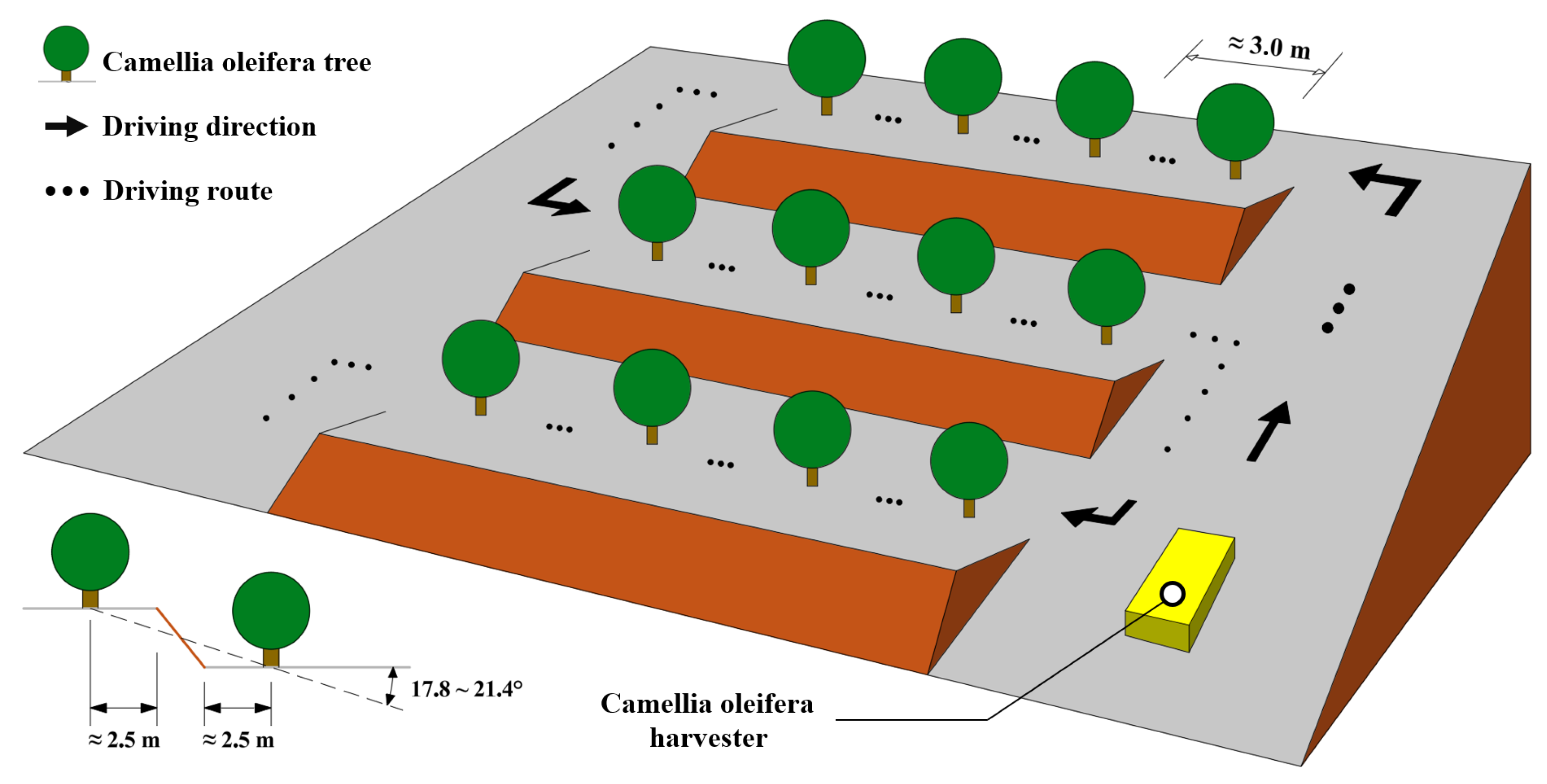
The experimental site is located in terraced red soil hilly terrain, incorporating both slope and flat land conditions. As shown in
Figure 18, the harvester followed a predetermined trajectory: initial uphill linear movement from the base of the right open area to the summit, followed by downhill harvesting along an “S”-shaped path before returning to the starting position. The experiment involved continuous harvesting of 12
C. oleifera trees without interruption. Temperature data were acquired using a signal analyzer at 1 Hz sampling frequency, with operators maintaining synchronous movement while monitoring equipment status. The harvesting procedure follows the detailed description in
Section 3.1.1.
Temperature measurement points were established on the surfaces of both hydraulic system and cooling system components. The experimental procedure involved: (1) attaching magnetic thermocouples to each measurement point, (2) connecting the thermocouple probes to the input ports of the dynamic signal test analyzer, and (3) transmitting temperature signals through the thermocouples to the analyzer for graphical representation of temperature variations. Prior to data collection, the harvester underwent sufficient warm-up at idle until stable engine compartment temperatures were achieved. The experimental apparatus included a dynamic signal test analyzer (manufactured by HOPE Technology Co., Ltd., Nanjing, China) and magnetic thermocouples (produced by NUOWEI Electromechanical Equipment Co., Ltd., Taizhou, China), with detailed instrument specifications provided in
Table 5.
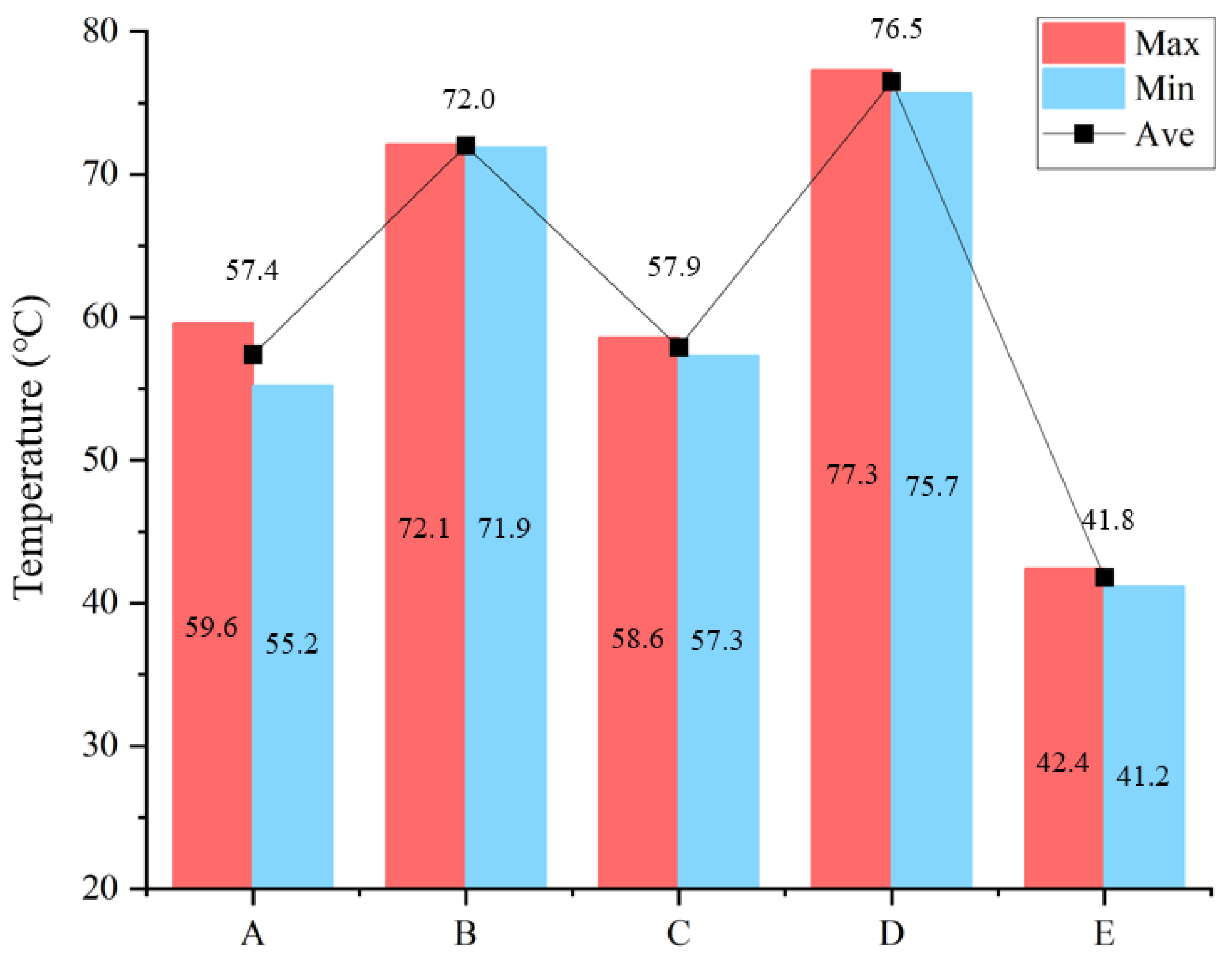
Figure 19 presents the detailed distribution of temperature measurement points within the engine compartment of the harvester before optimization. The sensor locations include: the top surface of the hydraulic pump (A), the surface of the densely arranged hydraulic tubing near the exhaust manifold (B), the hydraulic tubing between the radiator and compartment wall (C), the area adjacent to the radiator inlet (D), and the center surface of the valve assembly (E).
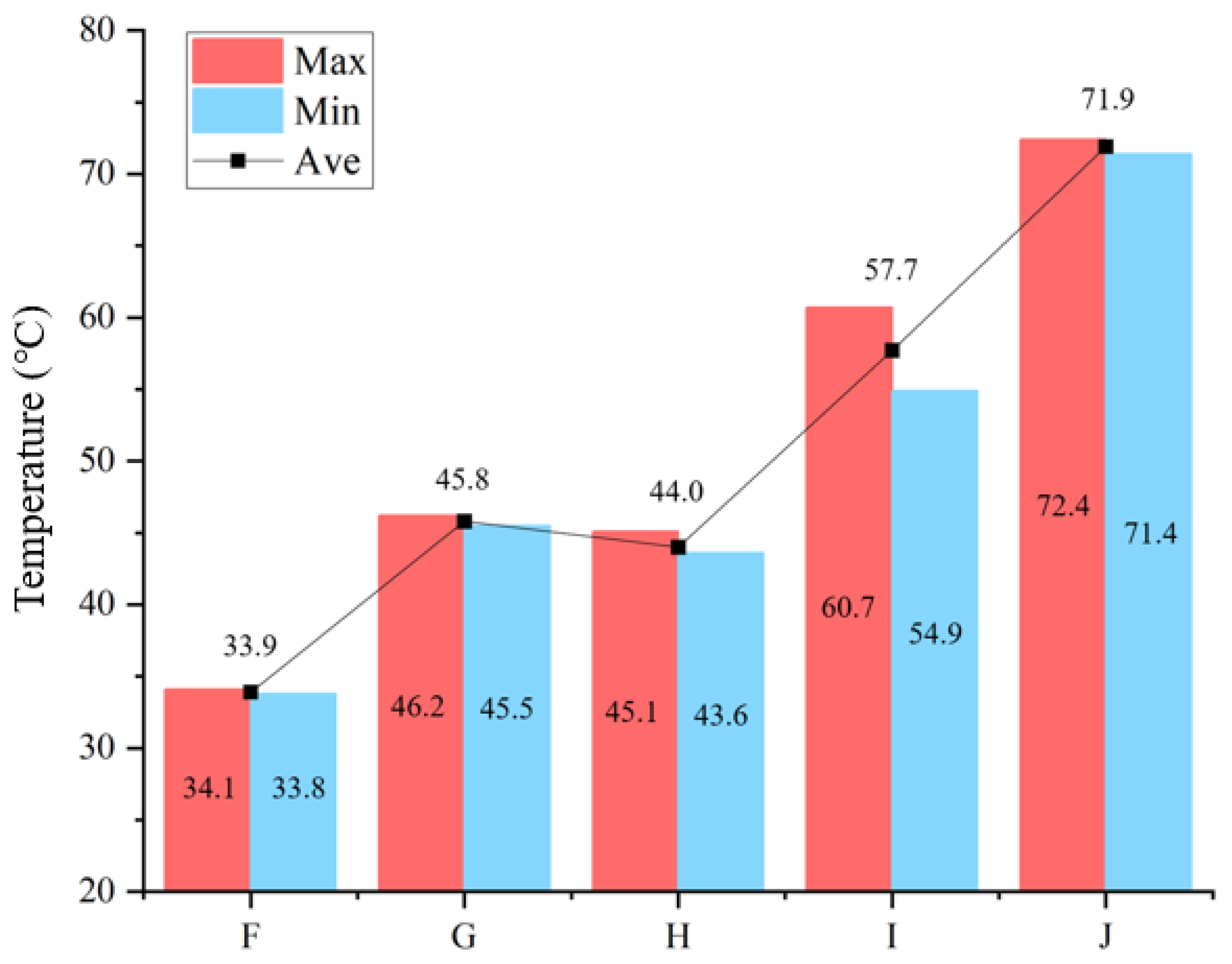
Figure 20 illustrates the optimized configuration of temperature measurement points in the harvester’s engine compartment. The sensor positions comprise: the center surface of the valve assembly (F), the densely arranged hydraulic tubing above the hydraulic pump (G), the top surface of the hydraulic pump (H), the hydraulic tubing adjacent to the exhaust manifold (I), and the area near the radiator inlet (J). This optimized sensor arrangement reflects the structural modifications implemented in the compartment redesign.
5.2. Analysis of Experimental Results
Due to interference from vibration and turbulence, the dynamic signal analyzer was unable to present the experimental data variations with sufficient clarity and accuracy. Therefore, Origin software was employed for signal data optimization.
Figure 21 displays the maximum, minimum, and average temperatures recorded at various sensor points in the pre-optimization harvester compartment. Experimental results indicate that Point A exhibited the most significant temperature variation (7.3% amplitude), while other points showed variations below 2.8%.
During testing, temperatures at Point A demonstrated strong correlation with engine speed variations and operational state transitions. Point B maintained consistently high temperatures with minimal fluctuation. Point C showed minor temperature increases during vibration mechanism operation, returning to baseline after deactivation. Points D and E exhibited minimal variations. All measurement points reached peak temperatures during vibration mechanism operation and minimum temperatures during trunk clamping.
At the 23 min mark (post vibration mechanism deactivation), the electronic system triggered an automatic engine shutdown due to detected abnormalities. Extended operation revealed progressively noticeable control response delays and increased turning radius, accompanied by declining vibration frequency that reduced harvesting efficiency and completeness.
Figure 22 presents the temperature characteristics at each sensor point for the optimized harvester. Point I showed the most pronounced variation (9.5% amplitude), followed by Point H, with other points below 1.5%.
In contrast to the pre-optimized harvester, the optimized version demonstrated no power loss or vibration frequency degradation during testing, with all experiments successfully completed. Post-test inspections confirmed that all components within the engine compartment remained in optimal operating condition.
5.3. Evaluation of Optimization Schemes
Comparative analysis of average surface temperatures for key components in both the cooling and hydraulic systems under operational conditions (
Figure 23) reveals consistent temperature reductions across all critical areas in the optimized harvester: approximately 18.9% at the valve assembly center surface (E/F), 23.3% at the hydraulic pump top surface (A/H), 6.0% near the radiator inlet (D/J), 21.0% in densely arranged hydraulic tubing areas (C/G), and 19.9% for hydraulic tubing adjacent to the exhaust manifold (B/I). This corresponds to an overall temperature reduction of 17.82%.
The experimental data analysis demonstrates significant performance enhancement of the optimized cooling and hydraulic systems under high-temperature conditions. Tripartite verification through numerical simulation results, empirical temperature measurements, and experimental observations confirms the effectiveness of the proposed optimization scheme in improving the internal thermal environment. The improvements manifest in three primary aspects: (1) notable reduction in operating temperatures of critical components, (2) improved temperature distribution uniformity, and (3) markedly enhanced system stability during sustained high-temperature operation. These results comprehensively validate both the efficacy of the optimization solution in achieving targeted thermal performance improvements and the scientific rigor of the methodological approach.
To evaluate long-term reliability, researchers conducted a 15-day field validation test at the C. oleifera plantation in Fenyi County, Jiangxi Province. Professional operators performed continuous 8 h daily harvesting operations with the optimized harvester, which successfully completed all assigned tasks. Throughout the testing period, all compartment systems maintained stable operation without performance degradation or operational anomalies. These practical application results further substantiate the solution’s effectiveness and reliability, demonstrating that the optimized cooling system meets engineering requirements for prolonged continuous operation.
6. Conclusions
This study conducted systematic and in-depth research focused on improving the thermal management performance of Camellia oleifera harvester compartments through structural optimization, yielding a series of theoretically valuable and practically significant results. By employing an interdisciplinary research methodology spanning problem diagnosis, optimized design, and experimental validation, a comprehensive technical framework for compartment cooling optimization was established, with the following key achievements:
(1) Based on fundamental principles of computational fluid dynamics and heat transfer, this study developed a three-dimensional simulation model of the harvester compartment. Through detailed flow field and temperature field analysis, the intrinsic mechanisms underlying the thermal issues were systematically revealed for the first time. The investigation identified three critical design flaws in the original configuration: (i) suboptimal spatial arrangement of key components causing airflow obstruction and impaired forced convection, (ii) excessive length and tortuous routing of hydraulic tubing traversing multiple high-temperature zones leading to abnormal oil temperature rise, and (iii) ineffective airflow guidance in the compartment cover design resulting in localized turbulence. These findings provided crucial theoretical foundations for subsequent optimization.
(2) The study proposed an integrated “numerical simulation + intelligent optimization” approach. Specifically: (i) systematic adjustment of compartment cover parameters via controlled variable methodology generated a comprehensive 420-case CFD database, (ii) high-accuracy surrogate modeling (R2 = 0.9587) using polynomial regression significantly reduced computational load, and (iii) APSO algorithm implementation identified optimal cover parameters (L = 295 mm, H = 30 mm, W = 570 mm; among them, W is a fixed value). This methodology not only enhanced optimization efficiency but also established a novel paradigm for thermal design optimization of complex mechanical systems.
(3) A comprehensive experimental verification was conducted through a professional testing platform integrated with a temperature acquisition system. Comparative tests demonstrated that the temperature reduction rates were approximately 18.9% at the central surface of the valve assembly, 23.3% at the top surface of the hydraulic pump, 6.0% near the radiator inlet, 21.0% in the densely arranged hydraulic pipeline region, and 19.9% in the hydraulic pipelines near the exhaust manifold. Compared with traditional models, the average temperature of key components in the harvester’s cooling system and hydraulic system decreased by 17.82%, indicating improved heat dissipation efficiency. Notably, during 15 consecutive days of field operation with a cumulative duration of 150 h, the optimized harvester exhibited no overheating-related failures. Furthermore, under daily 10 h operation in ambient temperatures ranging from 22 to 29 °C, the system consistently maintained the engine compartment temperature within a safe threshold, fully meeting the demands of high-intensity operations during the concentrated harvesting period of C. oleifera. These experimental results ultimately validate the effectiveness and engineering applicability of the proposed solution. The data conclusively demonstrate that the optimized solution significantly enhances equipment reliability and operational performance, exhibiting strong potential for engineering applications and widespread adoption.


 ,
, 


