Article

Design and Experimental Results Obtained with an Astragalus Digger Prototype

1
College of Mechanical and Electrical Engineering, Gansu Agricultural University, Lanzhou 730070, China
2
Dingxi Sanniu Agricultural Machinery Manufacturing Co., Ltd., Dingxi 743000, China
3
Shanxi Academy of Agricultural Sciences, Shanxi Agricultural University, Taiyuan 030031, China
4
Texas A&M University Corpus Christi, Corpus Christi, TX 78412, USA
*
Author to whom correspondence should be addressed.
Agriculture 2024, 14(5), 701; https://doi.org/10.3390/agriculture14050701
Submission received: 17 March 2024 / Revised: 18 April 2024 / Accepted: 26 April 2024 / Published: 29 April 2024
(This article belongs to the Section Agricultural Technology)

Abstract

:
Traditional methods for harvesting medicinal materials with long roots, like Astragalus membranaceus, require extensive soil excavation, leading to problems like inefficient soil separation, low stemming rates, and blockages in conveyor chains. To address these challenges, this study introduces a prototype machine capable of digging, separating soil, crushing soil, and collecting the medicinal materials in one continuous process. The paper focuses on the machine’s design and working principle, with theoretical analysis and calculations for key components like the digging shovel, multi-stage conveyor, and soil-crushing device. Specific structural parameters were determined, and the screening efficiency of the roller screen was analyzed using EDEM 2020 software, comparing scenarios with and without rollers. A motion model for the medicinal materials during conveyance was established, allowing for the determination of optimal linear velocity and mounting angle for the conveyor. Additionally, a motion model for the second-stage conveyor chain and rear soil-crushing device was used to optimize their placement, ensuring efficient soil crushing without affecting the thrown Astragalus. Compared to traditional Chinese medicine diggers, this machine boasts superior resistance reduction and soil-crushing capabilities. Compared with traditional harvesters, the drag-reducing and soil-crushing device of this machine is more efficient, reducing the damage to Astragalus during the harvesting process, reducing the labor intensity of farmers, and improving the quality and efficiency of Astragalus harvesting. Field experiments have shown that when the operating speed of the prototype is 1.0 m/s and the roller-screen speed is 130~150 rpm, the operating performance is optimal, and comparative experiments can be conducted under the optimal parameters. From the experimental results, it can be seen that the improved equipment has increased the bright-stem rate by about 4%, the digging and loosening rate by 97.42%, and the damage rate by 2.44%. The equipment design meets the overall design requirements, and all experimental indicators meet national and industry standards. This provides a reference for the optimization and improvement of the soil-crushing device and the structure of the Astragalus membranaceus harvester.

1. Introduction

Astragalus, a staple in traditional Chinese medicine (TCM), boasts a long history of cultivation in China, dating back to 1812. Over time, key production areas for authentic Astragalus have emerged in Gansu, Ningxia, Inner Mongolia, and Shandong provinces. In 2020, China’s national Astragalus planting area exceeded 2.47 × 10⁵ acres, with an annual output exceeding 1.1 × 10⁸ kg. Gansu has the largest planting area of Astragalus membranaceus, boasting 1.15 × 10⁵ acres. Longxi County, Gansu, even holds the prestigious title of “China’s Hometown of Astragalus” [1,2].
Mature Astragalus plants typically grow roots reaching 20–60 cm deep [3]; due to the deep penetration of roots and stems into the ground, there is less specialized machinery for harvesting Astragalus, and the mechanization rate of harvest remains low, at only 22%. Taking Gansu Province as an example, the planting areas of Astragalus membranaceus are concentrated at high altitude, in hilly and mountainous areas, characterized by small plots, numerous soil blocks, and large soil volume. This leads to low mechanization and high labor costs, seriously restricting the sustainable development of the industry.
In recent years, other countries have developed more comprehensive technical equipment systems, particularly for harvesting shallow root crops like potatoes and peanuts [4]. The VENTOR 4150 self-propelled potato harvester from Greemo AB in Sweden has a working width of up to 3 m. During the operation, it can complete flexible turns at any angle [5]. The CH-201C carrot combine harvester produced by Kubota Corporation in Japan has a maximum excavation depth of 300 mm, stable mechanical performance, fast operation speed, the capacity for neat and accurate removal of carrots, and a low harvest loss rate [6]. Notably, Shahgoli’s deep pine machine utilizes vibration damping principles to optimize energy consumption while maintaining effectiveness [7]. In the 1960s, China began importing foreign harvesting machinery [8]. These machines were adapted to local needs, with improvements in working methods and mechanisms for handling tasks like digging, separating soil, and collecting roots and stems of medicinal plants. Examples include the easy-to-operate underground fruit harvester described in Zhang Xuzhong et al. [9], and the automatic row-alignment system for root and tuber crop harvesters described in Li Tao et al. [10]. Chen et al. [11] discuss how a separation device addresses the challenge of harvesting rhizome-type medicinal materials such as Astragalus and licorice. She et al. [12] developed a two-stage conveyor hard-suspended licorice digger utilizing a two-stage lift chain conveyor, improving the conveyor belt’s lifespan. Yang et al. [13] developed a suspended yam harvester with optimized digging parameters intended to achieve efficient soil and yam separation. By carefully tuning the frequency, amplitude, and other parameters of the digging components, the rapid separation of soil and yam has been achieved. The licorice digger designed by Lipengcheng Wang et al. [14] explored the interaction between licorice and soil, which helps to develop harvesting techniques for deep-growing rhizome crops.
The above-listed developments significantly improved the level of mechanization of harvesting root crops. However, the existing medicinal-herb diggers have some limitations as well. Most of them rely on a single lifting and transporting chain to convey and lay strips of medicinal materials, requiring manual cleaning afterwards [15]. In addition, there is no Astragalus harvester specifically designed for hilly and mountainous areas, where harvesting continues to be done manually, leading to longer harvesting periods, and thus hindering a comprehensive land use [16].
In this paper, an Astragalus membranaceus harvester for hilly and mountainous areas is presented. A specialized soil-crushing digger has been designed, and field experiments were conducted on the entire machine. It is believed that this study will provide new references for theoretical and experimental research, as well as for the innovative design of automated machinery for harvesting rhizomes of medicinal plants.

2. Structure and Working Principle of the Machine

2.1. Structure and Main Technical Parameters of the Machine

As depicted in Figure 1, the apparatus primarily comprises a digging shovel, a suspension frame, a transmission system, a first lifting chain, a second lifting chain, a traveling ground wheel, a tensioning wheel, and various other components.
The Astragalus membranaceus harvester is designed for optimal performance in working conditions involving small and multiple soil blocks in northern land parcels. The primary components of this harvester include the digger shovel, roller screen, and conveyor chain, and the effectiveness of their design significantly impacts the quality of the harvesting process. Additionally, this machine features a soil-crushing roller device, enhancing its suitability for multi-soil block operations and thereby improving both the efficiency and quality of Astragalus harvesting. Detailed technical parameters of the digger can be found in Table 1.

2.2. Working Principle

When in operation, the digger is linked to the tractor via a suspension mechanism. The digging shovel is operated by the tractor’s hydraulic system to penetrate the soil, while adjustments to the relative height between the trapping wheel and the implement are made by altering the trapping wheel’s height. This allows for the customization of the digging shovel’s depth and angle, catering to various soil conditions. The Astragalus–soil mixture is conveyed to a roller screen through the digging shovel. Some soil clods fall back to the ground through the shaking action of the roller screen, while the remainder proceeds to the primary separation device. After passing through the primary separation device, smaller soil clods and gravel are sifted out, completing the initial separation process. For larger soil blocks that manage to pass through, a crushing roller positioned between the primary and secondary separation devices can break them down. The Chinese medicinal materials are directed onto the secondary separation device, where they undergo further separation and transport, ultimately ending up in the medicine collection box. At the rear of the two-stage lifting chain, a crushing roller is utilized to break up soil clods within the Astragalus mixed portion ejected from the end of the lifting chain, consequently enhancing soil permeability.

3. Design and Analysis of the Main Working Parts

3.1. Design of the Digging Shovel

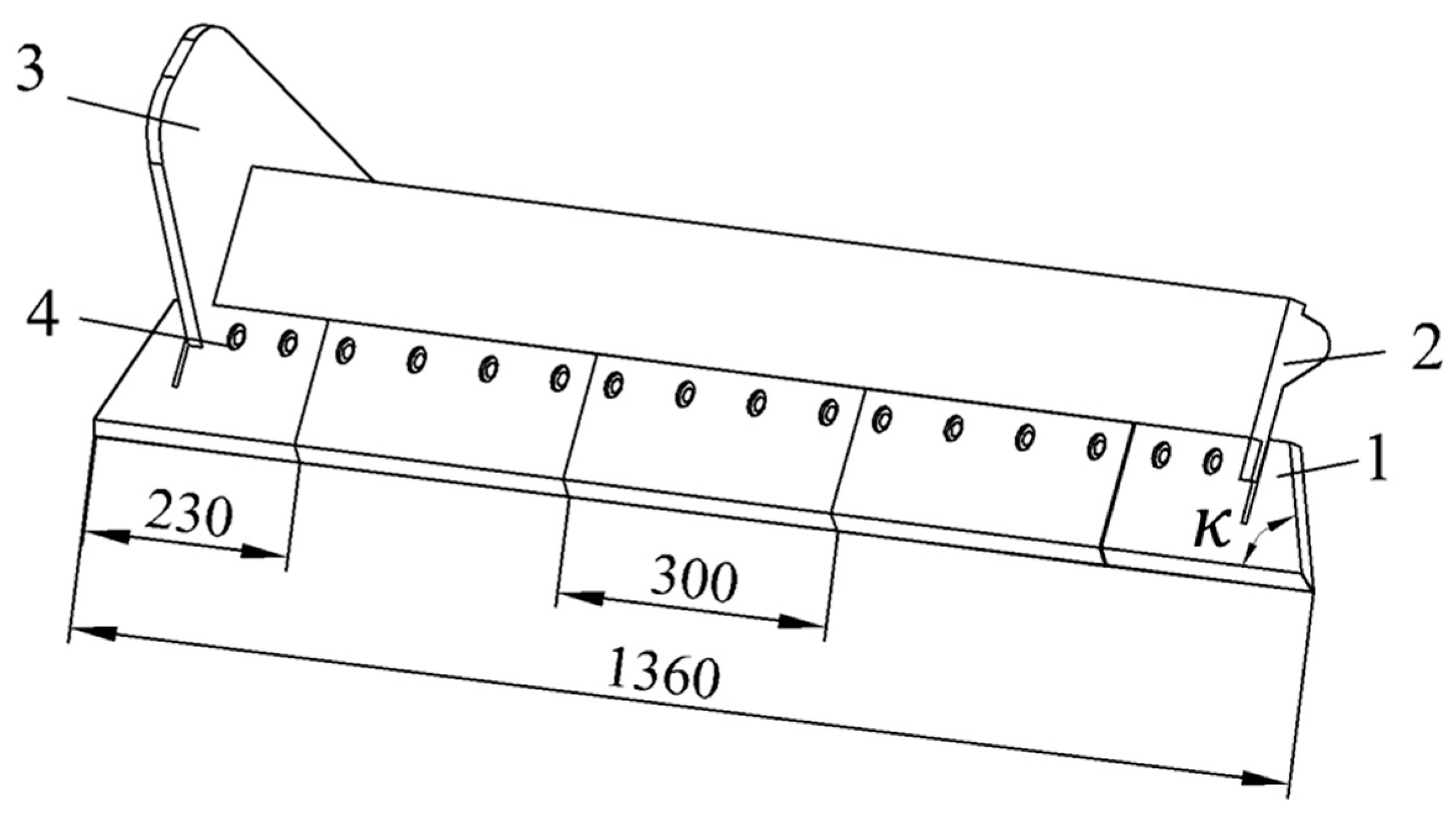
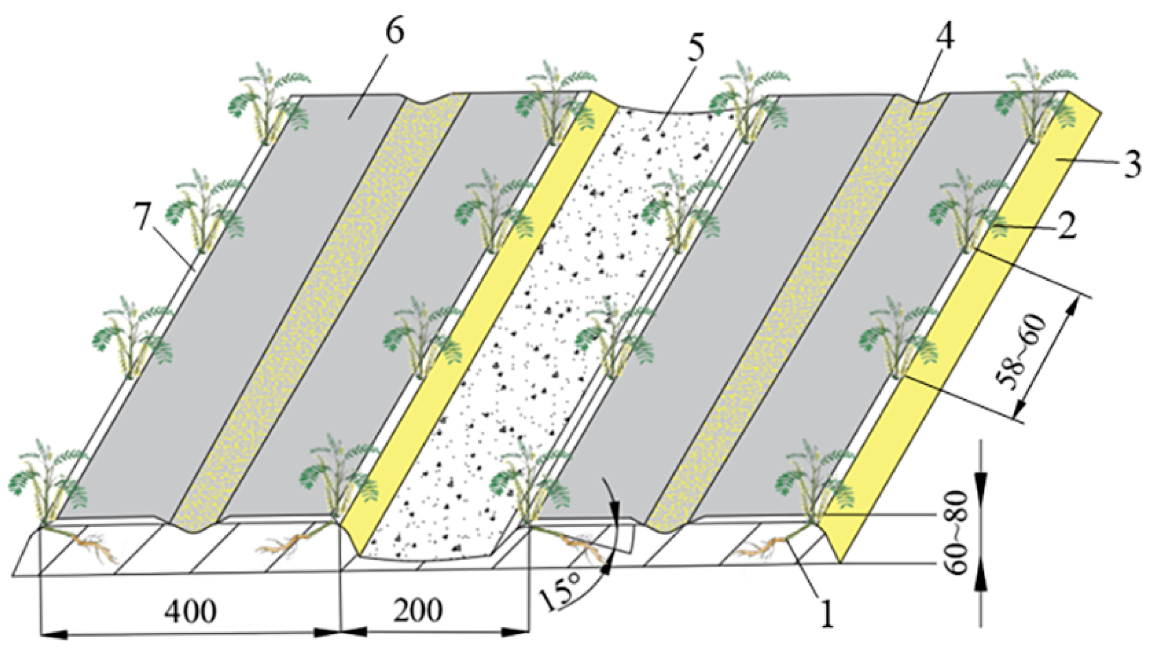
The primary production area of Astragalus is located in the northwest Loess Plateau region in China, where the plant demonstrates lower soil-fertility requirements. In order to adapt to the planting mode and meet the agronomic requirements, the designed Astragalus digger can harvest two plant rows at once; the ridge width is 400 mm, the row spacing is 200 mm. The root system of Astragalus is distributed in a branching pattern, with lengths between 50 and 150 mm. Considering the driving error of the equipment, the width of the excavator was set to 1360 mm (see Figure 2). It consists of multiple shovel blades, and the shovel head is fixed onto a positioning plate, which is then fixed onto the side plate of the machine body. In comparison to a single shovel, this multiple-shovel arrangement offers the advantages of reducing digging resistance and being a simple structure that is easy to manufacture. However, if there are too many shovels, they are prone to deformation during operation. Conversely, if there are too few shovels, material will be wasted during replacement. As a good compromise, five separate single shovels have been adopted. For convenient servicing, the entire digging shovel is designed with two types of shovel blades. Because the two end shovel blades have blade inclination angles, to ensure soil penetration performance their length was set to 230 mm, while the length of the middle shovel was 300 mm.
The determination of the inclination angle of the shovel blade is related to the mixture of medicine and soil and the friction angle of the shovel surface, which satisfies the following relationship, according to the following equation [17]:
ϖ + κ 90 °
  • ϖ —friction angle between the mixture of medicine and soil and the shovel surface.
  • κ —the inclination angle of the digging-shovel blade.
The rolling friction coefficient between soil and steel ranges from 0.5 to 0.7 [18]. Suppose the friction coefficient is 0.7 [19], then the friction angle ϖ is about 35°. In order to improve the ability to break the soil and reduce the resistance of digging, the inclination angle κ of the digging-shovel blade was set to between 20° and 40°.
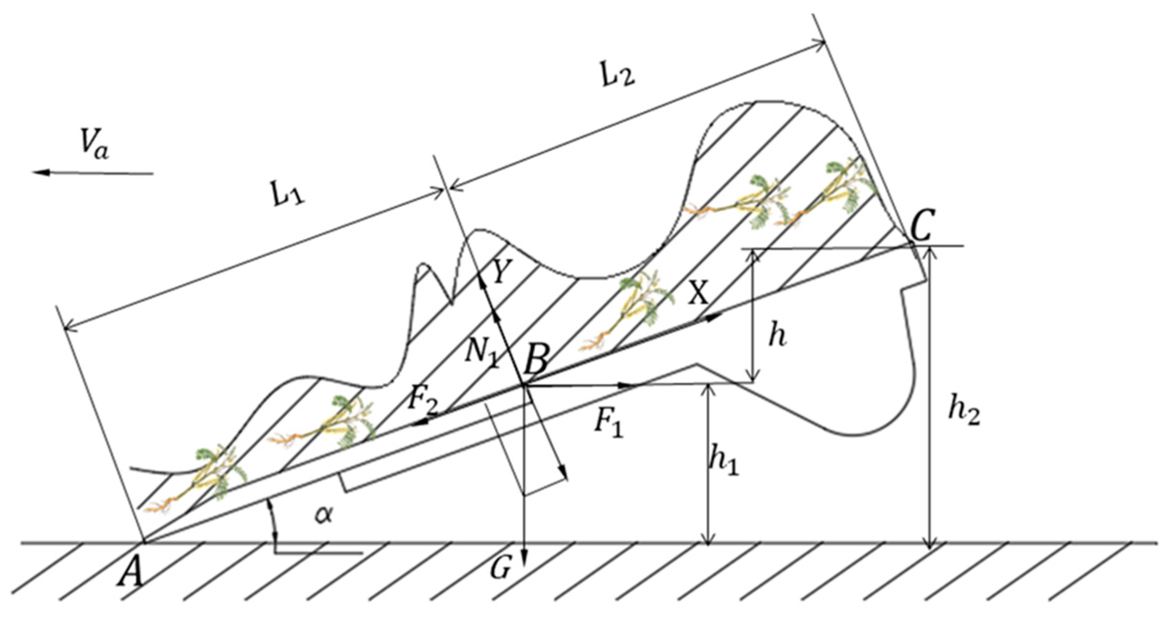
The design of the digger shovel is based on shape parameters, primarily involving the shovel length (L1 + L2) and the inclination angle of the digger shovel. The force distribution on the digging shovel is shown in Figure 3. According to this figure, the equilibrium equations on each direction are as follows:
F 1 cos α F 2 G sin α 0 N 1 F 1 sin α G cos α = 0 F 2 = μ N 1
where F 1 is the force on the digger when pushing soil forward (N); N 1 is the vertical force of the digging shovel on the soil (N); G is the gravity on the soil (N); F 2 is the friction force acting on the shovel surface (N); μ is the friction coefficient between the soil and digging shovel, μ = tan φ ; and α is the angle between the digging shovel and the ground.
From Equation (1) we further obtain:
α = arctan F 1 μ G μ F 1 + G
The length L 1 of the front end of the digging shovel can be expressed using the following relationship:
L 1 = h 1 sin α
To ensure that the digger can cut the soil block and have good sliding–cutting performance, while also ensuring that the rear end of the digger has sufficient height from the ground and that it does not touch the ground, the designed digging depth h1 is set to 200 mm. In turn, the length L 2 of the rear section of the shovel can be calculated using energy conservation, assuming that the Astragalus–soil mixture moves along the shovel surface at the forward speed V a of the unit to point B (see Figure 3):
E = 1 2 m V a 2
where m is the mass of the Astragalus rhizome–soil mixture (kg);
Assuming that the velocity V of the soil–Astragalus mixture, as it moves along the shovel surface from point B to point C, becomes zero, the soil starts accumulating at point C. The energy at point B is utilized to overcome the work W1 required for lifting the soil–Astragalus mixture to a height h and the work W2 needed to overcome friction along the digging-shovel surface L2. According to the conservation of energy, the equation can be formulated as follows:
  W 1 = G h = G L 2 sin α W 2 = G L 2 tan φ cos α 1 2 m V 2 = W 1 + W 2 = G L 2 sin α + G L 2 tan φ cos α
The total length L of the digging shovel can be expressed as:
L = L 1 + L 2 = h 1 sin α + V 2 cos φ 2 g sin ( α + φ )
where φ is the friction angle between soil and steel, (30°~36°) [20]; g is gravitational acceleration; (m/s2) and the forward speed V of the unit is 1.0 m/s.
To ensure optimal soil-penetration performance and seamless backward transportation of the soil–Astragalus mixture, the angle of the digging shovel can be adjusted using the ground wheel. The recommended adjustable angle for the flat digging shovel, denoted as α, is within the range of 30° to 40°, and the speed of gravitational acceleration g was determined as 9.8 m s−2.
Based on the calculation and analysis of the above parameters, the total length of the designed digging shovel L was determined to be 320 mm, for which it satisfies best the soil–Astragalus excavation needs.

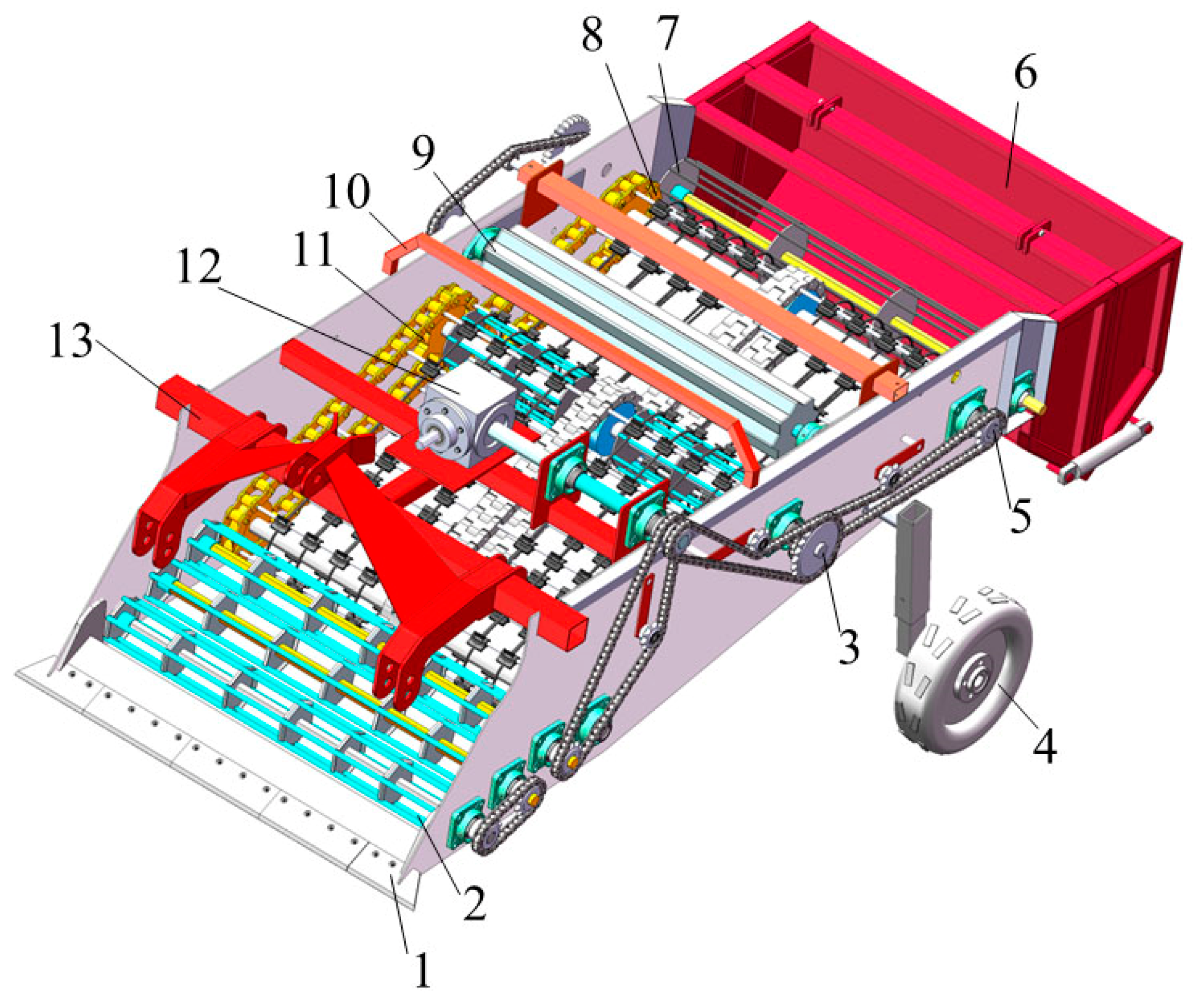
3.2. Roller-Screen Device

3.2.1. Design and Working Principle of the Roller Screen

In the actual work process, when the size of the soil block exceeds the clearance interval on the conveyor belt, it becomes challenging for the soil block to dislodge during the transmission process. Consequently, it ends up progressing through the subsequent conveying stages alongside the Astragalus, leading to a higher likelihood of soil blocks becoming mixed with the Astragalus. This mixing adversely affects the quality of the harvest. To address the above-mentioned issues, a roller screen, as illustrated in 
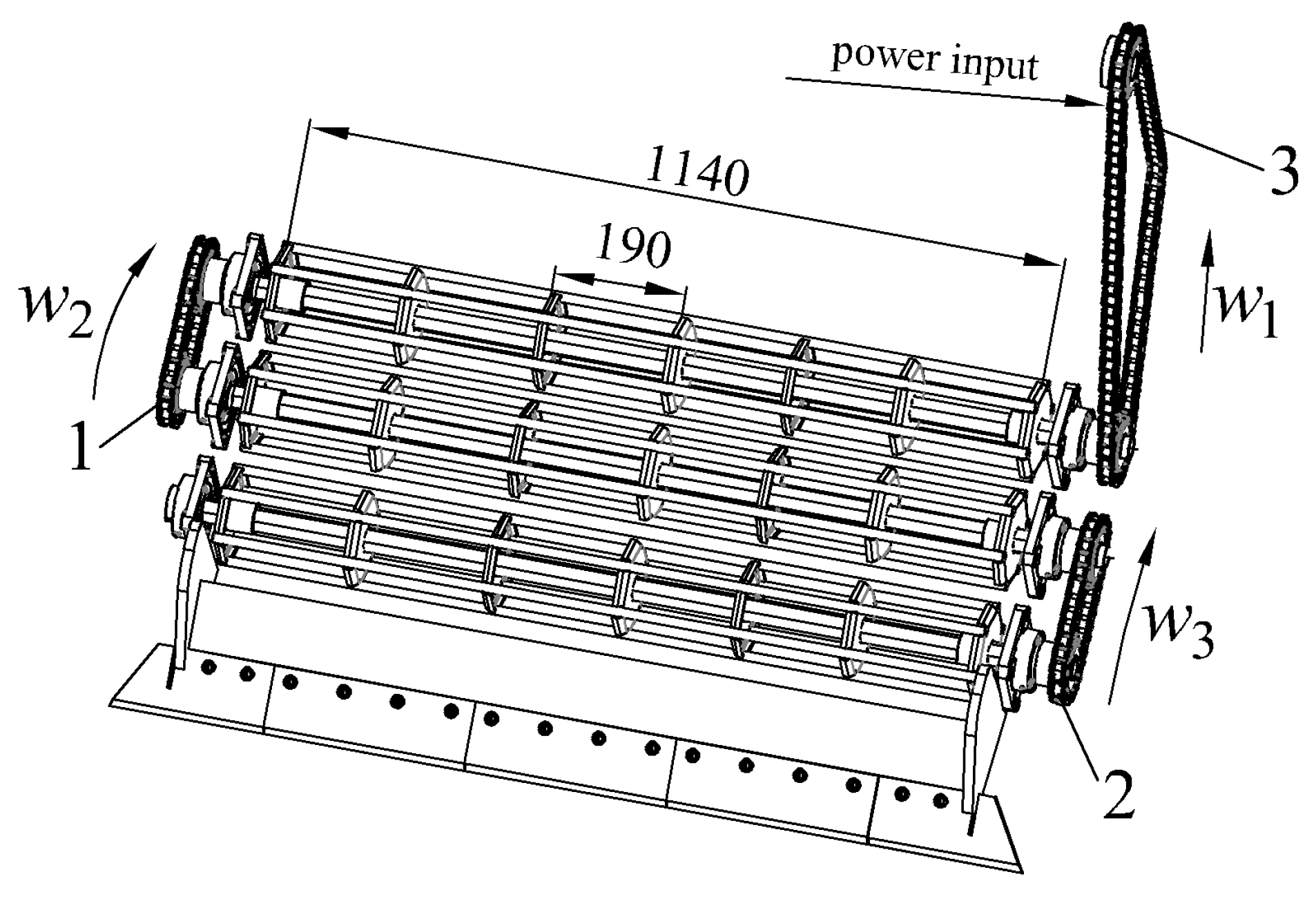
Figure 4, has been incorporated at the rear end of the digger. It primarily consists of a driving sprocket, rollers and link chains. Three sets of roller devices are evenly installed on the frame, with transmission sprockets located at both ends of each conveyor roller, facilitating a step-by-step power transmission. Additionally, these rollers are equipped with protective shells for the sprockets, safeguarding them against soil blockage.
The material of the rod is 65 Mn steel with a diameter of 10 mm. The fixed plate is made of 5 mm-thick 65 Mn steel plate, bent at 90°. Its hexagonal shape can fully disperse the pressure on each side, and thus increase the stability of the structure. The angle between adjacent sides is 120°, and a semi-circular structure with a diameter of 10 mm is cut at the angle. The rod is welded to the semi-circular structure on the fixed plate. The cross-sectional design of the drive shaft is a hexagonal shape with a side length of 20 mm, and the roller-screen device is fixed on the frame through the drive shaft.
Power from the tractor’s Power Take Off (PTO) is transmitted to input chain 2 through the gearbox (Figure 4). This chain drives the third roller, causing it to rotate, and simultaneously transferring power to chain 1. Chain 1, in turn, drives the second roller while transferring power to chain 3. Finally, chain 3 drives the first roller to complete the cycle. This sequence creates a “right-left-right” rotation pattern for the rollers. This roller screen device effectively increases the movement of the separation device on the soil, sifting out soil and stones. This reduces work resistance and improves the overall work efficiency.
Based on the intended working width of the equipment, the final drum-screen length is set at 1140 mm. To reinforce the steel bars and prevent soil from adhering to them, thereby reducing crushing efficiency and harvesting output, hexagonal reinforcement plates are welded to the vertical shaft at regular intervals. These plates are spaced 190 mm apart and connected to the connecting rods by welding. The rollers are arranged consecutively, with each pair angled slightly upwards. During operation, the sprocket drives the rollers to rotate in a clockwise direction, effectively crushing the soil.

3.2.2. Roller-Screen Force Analysis

To guarantee the smooth movement of excavated Astragalus onto the conveyor belt chain, it is crucial to determine the optimal speed of the roller screen. This can be achieved by analyzing the forces acting on the mixture on the roller screen, treating the combined soil and Astragalus scooped up per unit time as individual particles. 
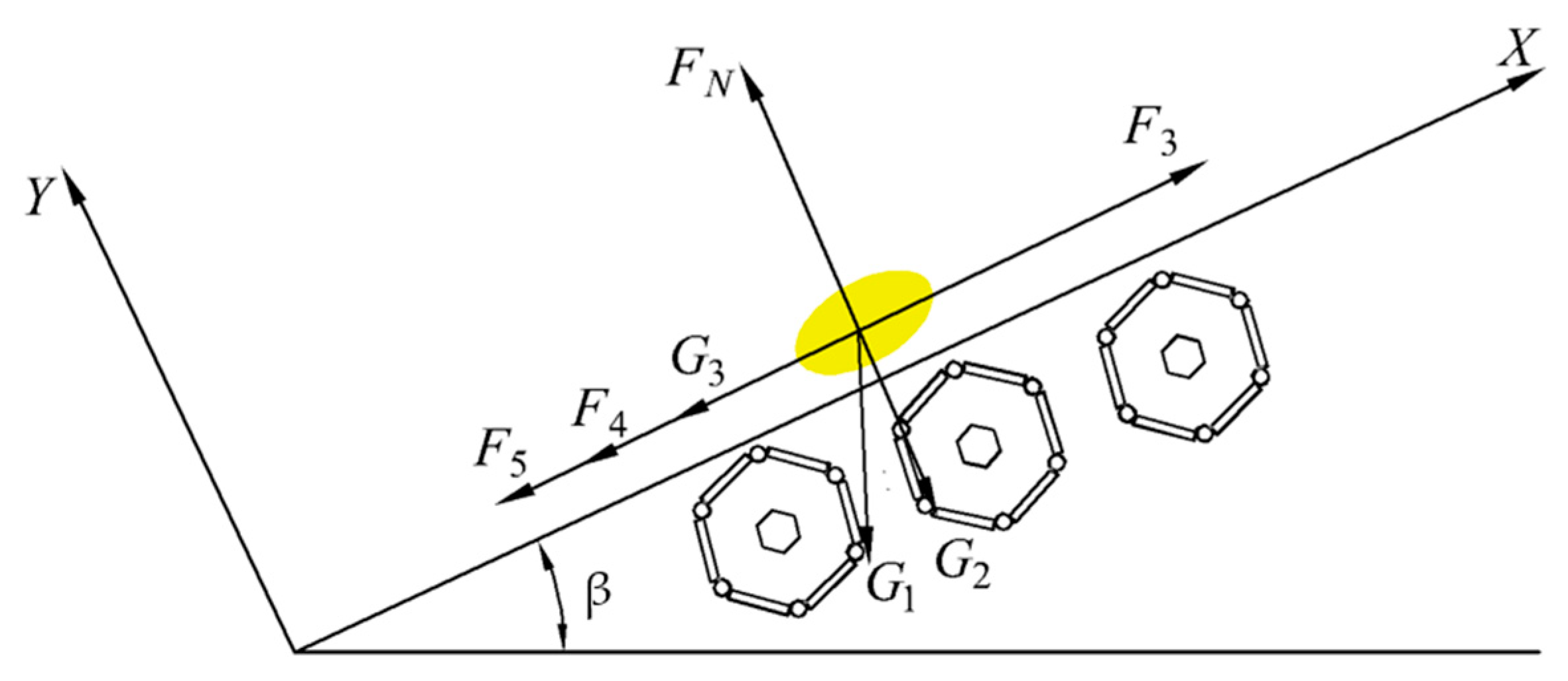
Figure 5 depicts the force analysis for the roller screen’s transport process. Figure 5 shows the following: β: angle between the roller screen and the ground (degrees); FN: force exerted by the roller screen on a particle (N); F3: conveying force received by Astragalus (N); F4: frictional force due to rolling during Astragalus movement (N); F5: frictional force generated at the neck of the roller screen on Astragalus (N); G1: gravitational force acting on a particle (N); and G3 and G2: components of gravity in the X and Y axes, respectively (N).
With these notations, the following equations can be written:
G 3 = G 1 sin β G 2 = G 1 cos β F 5 = ( Z q + G 1 cos β ) / cos γ ) ρ d D
where Z is the number of roller sieves in contact with Astragalus ( Z = 3); q is the mass of a single roller screen ( q = 4.9 kg); γ is the sliding friction between particles and roller screens ( γ = 26.5°); ρ is the equivalent friction coefficient of the roller bearing ( ρ = 0.15); d is the diameter of the roller journal (mm); and D is the diameter of the roller (mm).
Based on the same Figure 5, we can further write:
F 4 = k G 1 D / 2 + μ 1 F N
F 3 = m v 2 R = m w 2 R
where k is the rolling friction coefficient ( k = 0.05), and μ 1 is the friction coefficient between the soil and the roller screen ( μ 1 = 0.6) [21].
According to Equations (8)–(10), the condition to ensure smooth upward transportation of particles is:
F 3 G 3 + F 5 + F 4
The formula for meeting the critical speed for smooth transportation of particles is:
w 2 D G 1 sin β + ( Z q + G 1 cos β / cos γ ) ρ d + 2 k G 1 m D R
n = 60 w 2 π 30 π · D G 1 sin β + ( Z q + G 1 cos β cos γ ) ρ d + 2 k G 1 + D μ 1 G 1 cos β m D R
For the roller diameter D = 150 mm, journal diameter d = 32 mm, angle between the roller screen and the ground β = 20°, and mass of Astragalus and soil blocks per unit time 500 kg, the calculated critical speed of the roller screen is 137.2 rpm. However, to accommodate operational needs in various plots, the operating speed was set to 150 rpm.
If we treat the mixture of Astragalus and soil (which needs to be continuously separated and transported upwards) as a single particle, the analysis shows that to achieve stable upward transport, at least three roller supports must be employed. The root and stem growth length (L₃) of Astragalus is between 200 mm and 600 mm, and for the upper limit L₃ = 600 mm, the approximate spacing between the rollers should be:
b = 1 3 L 3 = 200   mm
To ensure timely separation of the roller spacing, it is necessary to match the assembly pitch of the drive sprocket. Therefore, the roller-shaft spacing was taken as b = 170 mm.

3.2.3. Simulation Parameter Setting for Roller-Screen Operation Stroke

To assess the effectiveness of installing a roller screen in improving separation efficiency, a comparative analysis was conducted using the discrete element method (DEM) in a simulated experiment. Two models were created: one equipped with a roller screen and another without. The material composition of the models should be 65 Mn steel. Experiments were then run with both models to compare their separation performance. For the contact model between soil particles and each other, as well as between soil particles and the separation device, the Hertz-Mindlin (no-slip) model [22] was chosen. The relevant simulation parameters were set as specified in Table 2 [23].
Two plot model diagrams, each measuring 8000 mm (length) × 1400 mm (width) × 600 mm (height), were created in SolidWorks 2020 based on the characteristics of harvest plots in the northwest region. These models were then imported into EDEM 2020 software. A particle factory, aligned with the plot height, was set up within EDEM. A total of 1.5 million soil particles were generated and allowed to fall freely under the influence of gravity within the plots. The entire simulation ran for 9 s.

3.2.4. Simulation Process and Result Interpretation

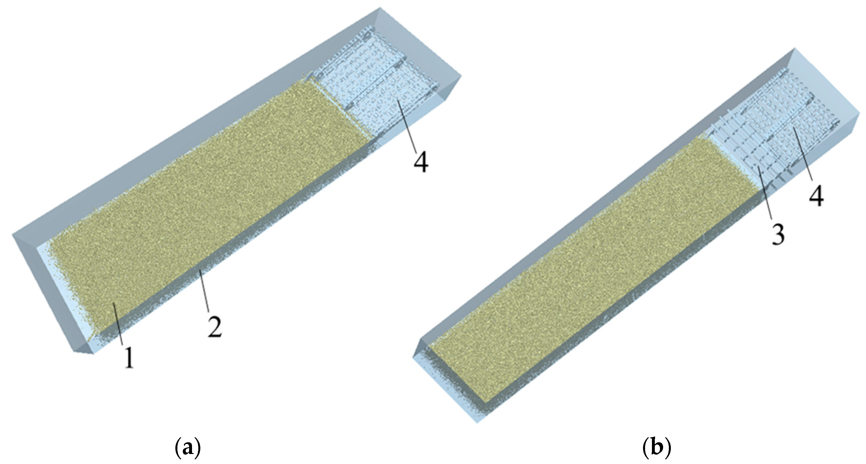
Prior to initiating the simulation, two filtering models had to be established within SolidWorks and saved in the .stp format. Subsequently, these models were imported into EDEM software, as depicted in Figure 6. Additionally, the roller-screen speed was set to 150 rpm. For both the roller screen and the conveyor chain, the forward speed was set to 1.0 m/s, and the conveyor-chain speed was set to 2.2 m/s. In the simulation of the roller-screen operation, the effects of material wear and frictional heat transfer were neglected.
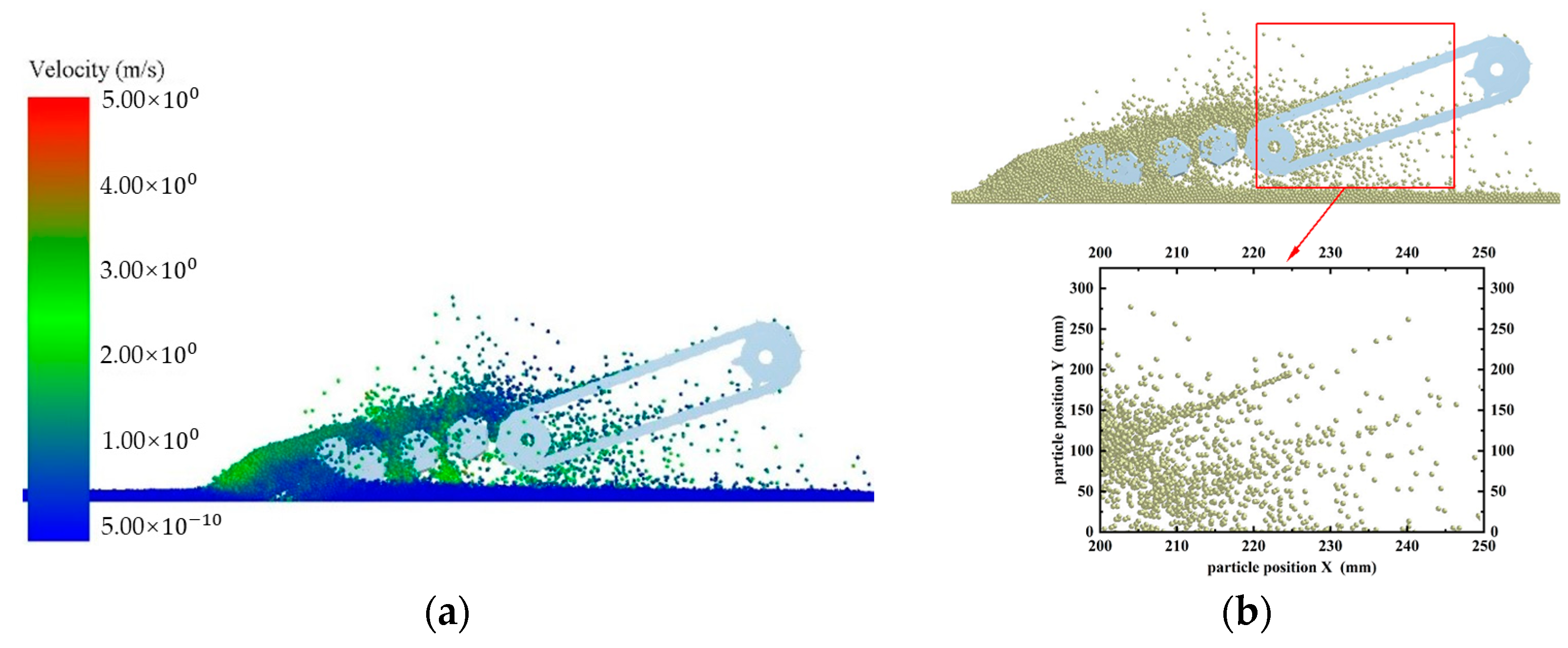
The effect of soil particles entering the conveyor chain when different simulation devices operate stably is shown in Figure 7 and Figure 8. From these simulation diagrams it can be seen that the particle density entering the conveyor chain when the roller screen is installed is smaller than that when the roller screen is not installed. To determine the screening efficiency of the roller screen, data collection and processing during the experimental process were carried out through the post-processing module of the discrete element simulation software EDEM 2020. Due to the inability to directly calculate the number of particles screened by the roller-screen device, the screening efficiency of the roller screen can be indirectly calculated by measuring the number of particles falling into the conveyor chain. Data collection was conducted at the initial positions of two different models of conveyor chains. Using the Grid Bin Group option of the Setup Selections module, a measuring box with a width and length of 700 mm and 540 mm was set every 1 s along the direction of motion of the roller-screen device from the initial stage position. The total time was set to 9 s. The number of particles passing through each box was measured, and a data table was output to calculate the screening efficiency. The results are shown in
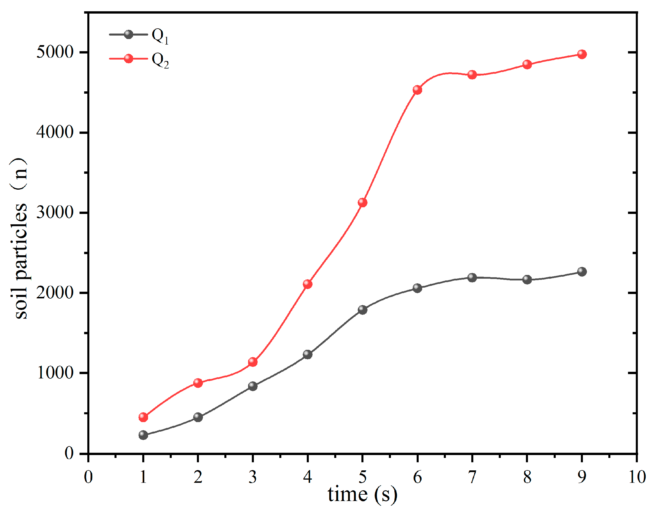
 Figure 9.
The Q1 line represents the number of soil particles measured without the installation of the roller screen, while the Q2 line represents the number of soil particles measured with the installation of the roller screen. In both cases, the particle numbers tend to stabilize after about 6 s. Without a roller-screen device, the number of particles measured during the stable period is between 4500 and 5000. With a roller-screen device, the number of particles measured is between 2000 and 2500. The actual number of particles has been gathered in Table 3.
After the number of particles entering the conveyor chain from two different devices had stabilized, the screening efficiency of the roller screen was calculated for the simulation time between 6 and 9 s. The formula used was:
η = ( 1 Q 1 Q 2 ) × 100 %
where η is the screening efficiency of the roller screen, (%); Q 1 is the number of soil particles measured by installing a roller-screen device; and Q 2 is the number of soil particles measured without the installation of a roller-screen device.
According to Equation (15), the screening efficiency of the roller screen is approximately 56.3%. Figure 7b shows that that soil particles directly enter the conveyor-chain device through the digger shovel, resulting in low particle dispersion and high density, which increases the operational resistance of the conveyor-chain device and affects the permeability of the soil. As can be seen in Figure 8b, the soil particles entering the conveyor chain after screening have a high degree of dispersion. The main reason for this situation is that the roller screen exerts a greater force on soil particles during high-speed rotation, and the soil particles are subjected to greater centrifugal and shear forces, increasing the interaction between particles and resulting in dispersion and separation effects. Meanwhile, the high-speed rotation of the roller screen also increases the impact force on soil particles, resulting in a higher horizontal particle velocity and greater dispersion of soil particles. The pore structure of the soil will also become looser, increasing the soil permeability and thus providing a good growth environment for the next crop of Astragalus membranaceus.

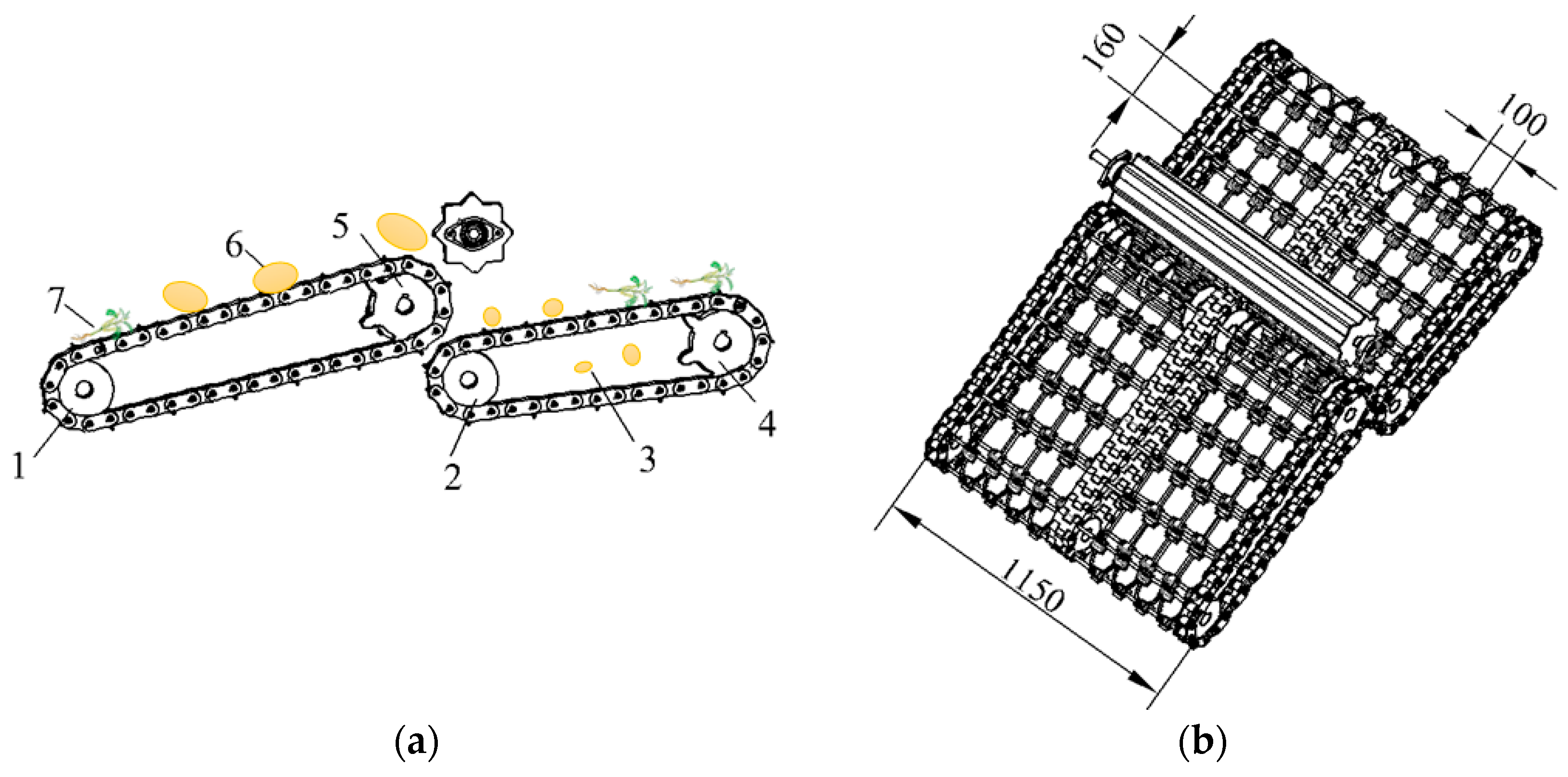
3.3. Flexible Separation-Conveyor Device

As shown in Figure 10, the Astragalus digger implements a two-stage conveyor-chain separation operation. Digging out the mixture of Astragalus–soil with a shovel, it enters the conveyor chain through a roller screen. The installation angle of the conveyor chain directly determines the yield of Astragalus. This structure mainly consists of a first-stage conveyor chain, a second-stage conveyor chain and a flexible screen.
The length of the rhizomes of Astragalus is mostly above 200 mm, so the separation gap is designed to be 160 mm × 100 mm, and the total length of the separation rod is 1050 mm. To ensure fixed spacing during the separation process, the separation rods are fixed through the holes in the conveyor chain and can rotate. This ensures that the distance between the separation rods does not change during the normal operation of the conveyor chain.
The first stage of the conveyor chain mainly separates the mixture screened by the roller screen, and transports Astragalus rhizomes mixed with larger soil blocks backwards. A soil-crushing device installed behind the first-level conveyor chain will break the larger soil blocks. The broken soil then falls onto the second-level separation device, along with Astragalus. The soil blocks are separated in the gaps of the second-level separation device, and Astragalus is collected into the collection box as the conveyor operates.

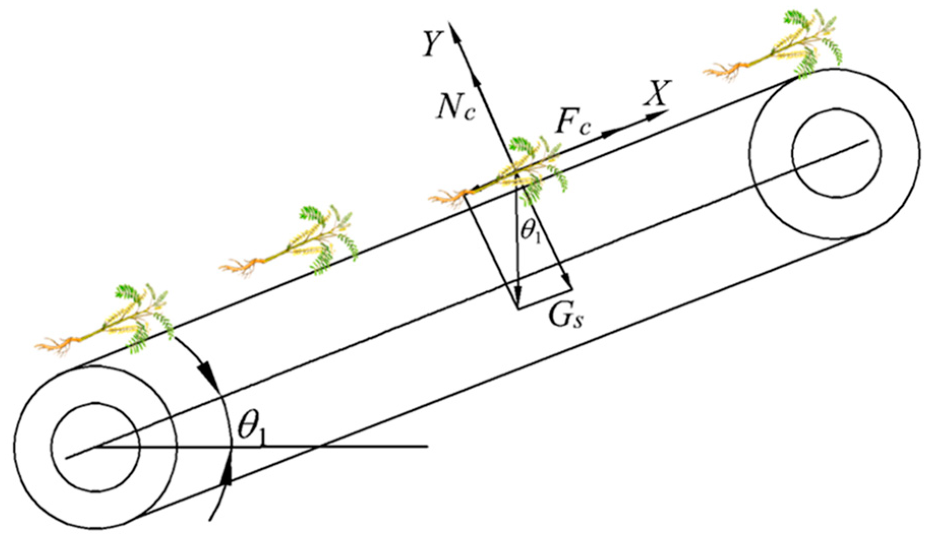
3.3.1. Calculation of Installation Angle of the Conveyor Chain

When the mixture is transported along the separation device, a suitable installation angle is required to ensure that medicinal materials do not slide down in the opposite direction of the conveyor chain. The installation angle is determined through the force analysis of Astragalus on the conveyor chain. When the inclination angle of the conveyor chain is at the critical value θ 1 , the Astragalus is slipping backwards, corresponding to the force configuration as shown in Figure 11.
The equilibrium equations are the following:
F c G x sin θ 1 = 0 N c G x cos θ 1 = 0 μ c N c = F c
where θ 1 is the critical inclination angle of medicinal materials sliding on the conveyor belt (°); G x is the weight of medicinal materials (N); F c is the frictional force between the medicinal materials and the conveyor belt (N); N c is the support force of the conveyor chain upon the medicinal materials (N); and μ c is the static friction coefficient between medicinal materials and the conveyor chain.
The static coefficient of friction μ c between the medicinal plants and the conveyor chain is 0.45 [24], and the critical inclination angle for medicinal materials to slip on the conveyor chain is 24.9°. If the installation angle is too big, the harvest is prone to rolling, while if the angle is too small, the overall size of the machine will be too long and power consumption will increase. Therefore, the installation angle in working condition was set to 30°, which exceeds the critical inclination angle, causing the medicinal material to slide downwards.
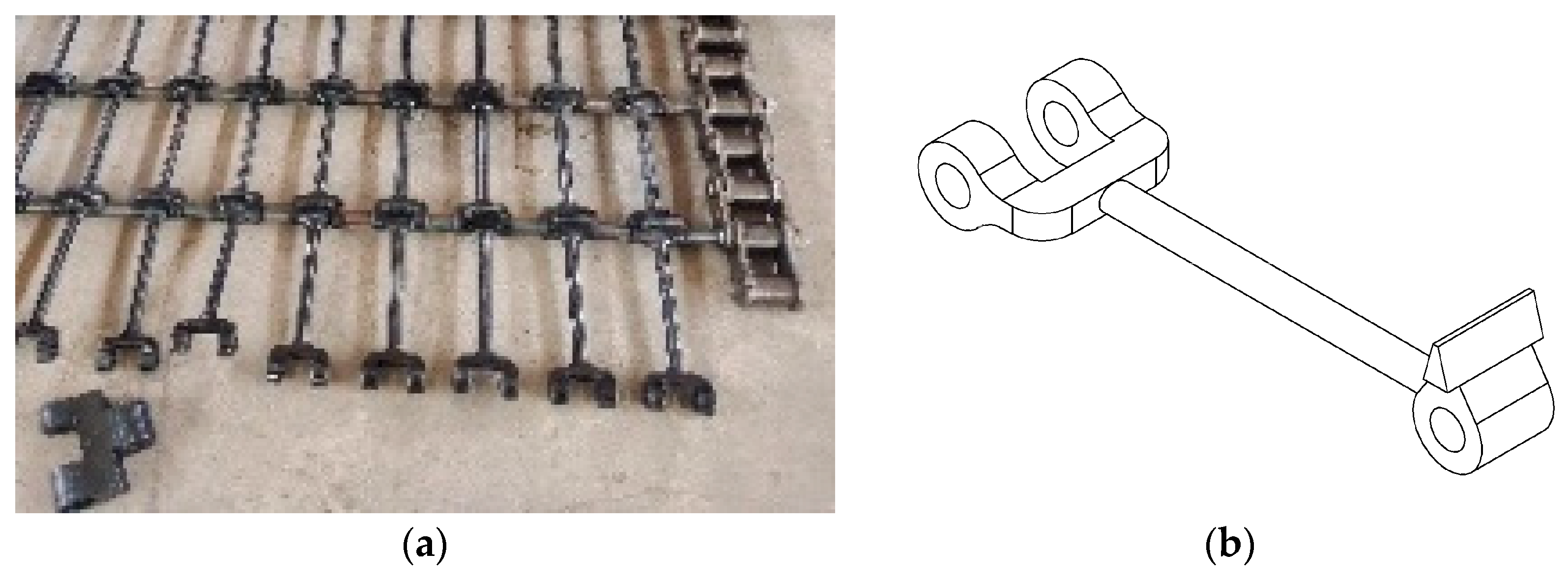
To solve this problem, a flexible screen was installed on the conveyor chain to facilitate the smooth transportation of Astragalus along the lifting direction. The flexible screen can additionally reduce the vibration damage and the deformation and fracture of the Astragalus during the separation process, thus maintaining its structural integrity and improving the efficiency of separation.
The screen strips between the conveying rods are shown in Figure 12. There are 12 mm through holes at both ends of the sieve chain, which are connected by rubber rods with a length of 124 mm and a diameter of 8 mm. The sieve chains are embedded and connected, and the rods pass through the through holes of the rubber mesh and connect to the chain. The diameter of Astragalus is generally between 0.5 and 3 cm. Considering factors such as shaking during operation, to achieve the conveying process the designed height of the end of the sieve is 30 mm. Therefore, even if the angle of the conveyor chain exceeds the critical inclination angle during operation, the medicinal materials will not slide downwards during the conveying process. Compared with the more common straight-rod installation, this arrangement allows the medicinal materials to be better maintained in a fixed position during the separation and transportation process, reducing its damage rate.

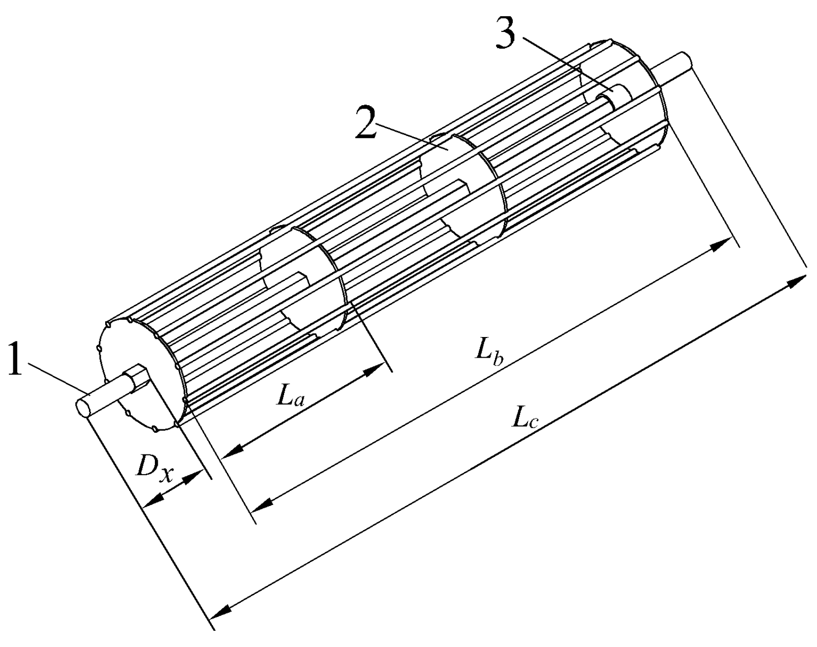
3.3.2. Rear Soil-Crushing Roller Device

In order to achieve better separation between medicinal materials and soil, a soil-crushing roller was installed at the rear end of the second-stage conveyor chain. Considering that there are fewer remaining soil blocks at the end of the conveyor, combined with the overall size and weight of the machine, the designed soil-crushing roller is a rod type. These rods not only save materials but also reduce the weight of the soil-crushing device.
As shown in Figure 13, the soil-crushing roller consists of a driving shaft, a fastening ring, a disc, and a rod. The soil-crushing roller is driven by the active shaft of the second-stage conveyor chain. When the digger operates, the soil-crushing roller begins to rotate and breaks down larger soil blocks into smaller particles. According to the width of the machine operation, the length L c of the soil-crushing roller shaft is designed to be 1400 mm. Compared to traditional circular shafts, this device uses a hexagonal shaft, which provide more bearing area where the reinforced disks are assembled, and to resist better torsional loads. The shaft is also lighter weight, thereby reducing manufacturing costs and the required actuating power.
The distance D x between the disc and the side frame is 137 mm, and the actual working width L b is 1120 mm, choosing an appropriate size based on specific land conditions and soil conditions, and selecting a diameter of 200 mm. The soil-crushing roller is evenly divided into three sections horizontally, and each section is welded with a disc that plays a reinforcing role on the soil-crushing rod. The length D of each section is 372 mm, and 10 soil-crushing rods with a diameter of 12 mm are evenly distributed around them, which are attached by welding.
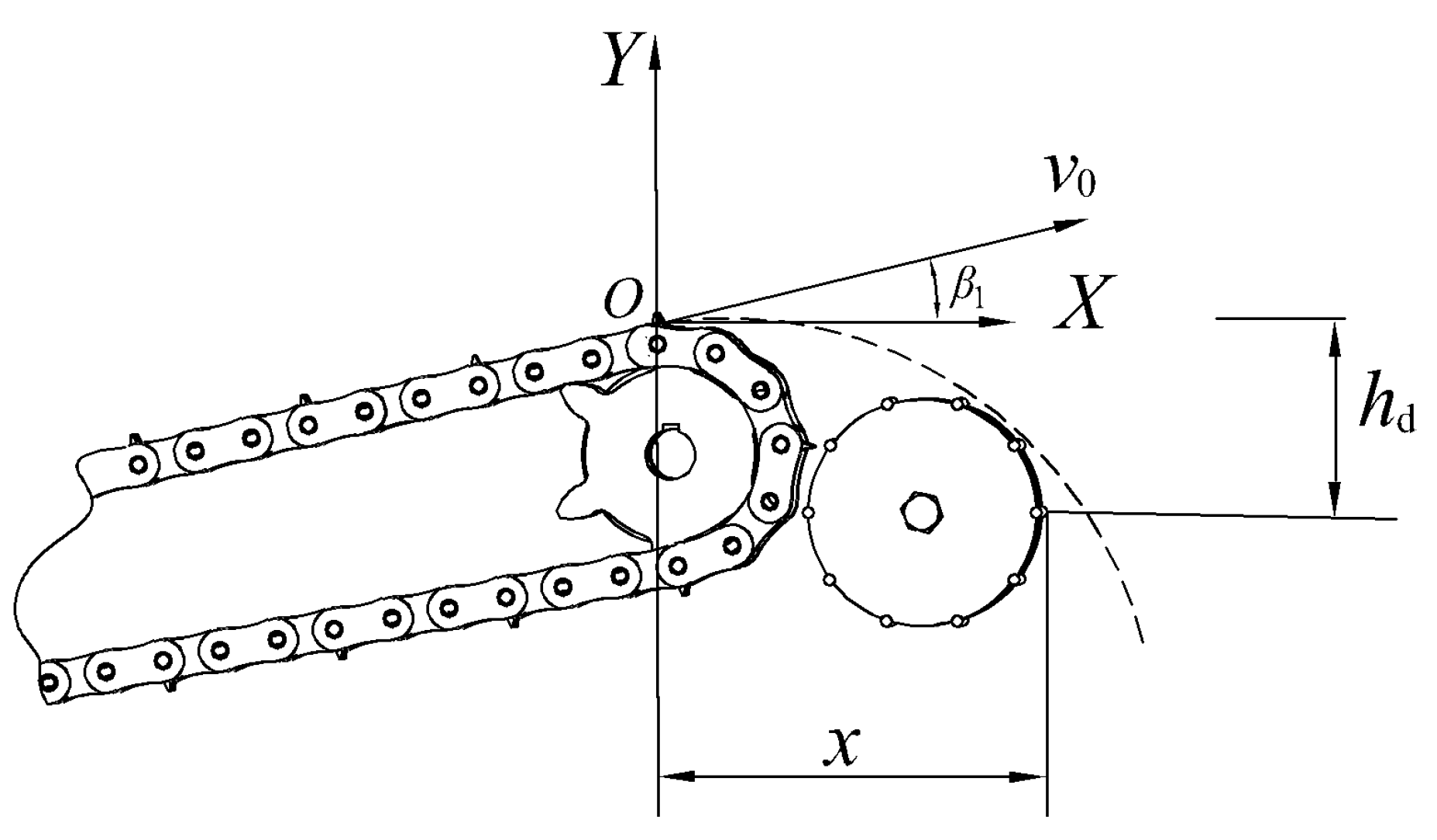
Astragalus is transported to the end of the second-stage conveyor chain and thrown backwards at a certain speed. To ensure that the installation of the rear soil-crushing device does not affect the thrown material, the horizontal displacement of Astragalus during throwing needs to be considered. Therefore, a motion analysis was conducted, as shown in Figure 14.
Due to the angle between the conveyor chain and the ground, when Astragalus is transported to point O and thrown out of the second-stage conveyor chain, its velocity is the same as the velocity of the conveyor chain. Ignoring the impact of collisions and air resistance between Astragalus, the soil blocks and the conveyor chains, the Astragalus is thrown out and undergoes uniform linear motion in the horizontal direction. In the vertical direction, it first reaches the highest point and then undergoes uniform acceleration with a linear motion downwards. The equation of motion for reaching the highest point in the vertical direction is as follows:
1 2 m 1 v 0 2 sin β 1 = m 1 g h d 1
where m 1 is the mass of Astragalus (kg); h d 1 is the vertical rise height (mm); β 1 is the angle between the second-stage conveyor chain and the ground level (°); and g is gravitational acceleration (m/ s 2 ).
According to the installation angle of the first-level conveyor chain, the installation angle of the second-level conveyor device is taken as 30° and the speed of the second-level conveyor chain is taken as 2 m/s. By substituting it into the above formula, the maximum height of rise is calculated to be 50 mm.
According to the installation position of the rear soil-crushing roller device, taking x as 300 mm and h d as 200 mm, then there is the following formula:
h d 1 + h d = 1 2 g t 2 x 1 = t v 0 cos β 1
where x 1 is the actual horizontal distance, (mm).
Substituting this into Equation (18), the calculated value is x = 391 mm, which is greater than the farthest distance x for installing the soil-crushing device, thus satisfying the operating conditions.

3.4. Crushed-Soil Roller

Given the large amount of soil and numerous soil blocks, combined with the actual harvesting situation of Astragalus in northern arid areas of China, a soil-crushing roller was installed at the end of the first-stage conveyor chain. This can crush the compacted soil blocks, achieving the effect of crushing the soil and reducing the working resistance of the machinery.
Figure 15 shows the structural diagram of the soil-crushing roller device of the Astragalus digger, which consists mainly of a soil-crushing roller, driving shaft, support rod and fixed plate. The structural dimensions and spatial position of the soil-crushing roller directly affect the quality of the soil crushing. Cylindrical soil-crushing rollers have limited soil-crushing capacity, and are not ideal for treating randomly-shaped-soil treatment, resulting in low soil-crushing efficiency. Therefore, this device is welded with Q235B angle iron with a thickness of 3 mm and a side length of 40 × 40 mm. The advantage is its sturdy structure, which is suitable for handling large and hard soil blocks. It can also be customized according to actual needs. The drive shaft passes through the covers at both ends of the roller and is connected to one side of the gear. The two ends of the roller are connected to a fixed plate at a distance of 40 mm from the frame. The two ends of the support rod are fixed to the frames on both sides with 10 mm bolts and welded to the fixed plate to fix the soil-crushing roller. The roller-screen device is driven by the active shaft of the secondary conveyor chain. In non-sticky heavy soil, the device can be disassembled through bolts [25], thus reducing the power consumption of the unit.

3.4.1. Calculation of Diameter of Soil-Crushing Roller

As shown in Figure 15, the soil block can be approximated as a circle with a diameter of d. To press the soil block into the soil-crushing roller, the following condition needs to be met:
F Q   cos γ 1 N   sin γ 1
where F Q is the friction, F Q = N ε , (N).
ε is the friction coefficient between the soil-crushing roller and the material in contact.
Then, the following inequality (20) can be derived:
ε sin γ 1 cos γ 1
According to the geometric diagram, it can be inferred that
cos γ 1 = d x + Z d x + d z
sin γ 1 = 1 ( d x + Z d x + d z ) 2
Combining Formulas (21) and (22) into inequality (20) we obtain the following:
ε ( d x + d z ) 2 ( d x + Z ) 2 ( d x + Z ) 2
d x = d z Z d z 1 + ε 2 1 + ε 2 1
According to Equation (24), the minimum diameter d x of the soil-crushing roller is related to the friction coefficient ε , soil block diameter d z , and the vertical distance Z between the soil-crushing roller and the sieve. Based on actual measurements of soil mixtures, the friction coefficient ε was taken between 0.5 and 0.7 [18]. The minimum diameter of the soil block that can be sieved by the conveyor chain is 100 mm. In order to achieve the function of crushing soil, it is required that the vertical distance between the roller and the screen is less than 100 mm. Therefore, the distance Z between the roller and the sieve was 80 mm, the diameter of the soil block was 100 mm, and the diameter of the soil-crushing roller was 40–180 mm. The larger the diameter of the soil-crushing roller, the better the soil-crushing effect. However, if the diameter is too large, the power consumption increases. A good compromise that satisfies the harvesting conditions was a 160 mm diameter of the soil-crushing roller.

3.4.2. Calculation of the Width of the Soil-Crushing Roller

The length of the soil-crushing roller can be determined according to the actual agricultural requirements of planting. The Astragalus digger can achieve two rows of digging and the working width can be calculated according to formula (25):
A = D a + 2 l + 3 e + 2 c
where D a is the average line spacing (mm); l is the average width of ridge surface (mm); e is the standard deviation (mm); and c is the tractor driving deviation (mm).
Under the real-time control of the operator, the driving deviation of the tractor can be controlled within 30 mm. The comprehensive standard deviation formula is
e = e D 2 + e l 2
where e D a is the standard deviation of line spacing (mm) and e l is the standard deviation of the average width of the ridge surface (mm).
Based on actual measurement data, the calculated standard deviation is 6.23 mm, which can be taken as 6 mm, the average line spacing D a is 200 mm, and the average width of the ridge surface is 400 mm. Combining the agronomic requirements of two rows of ridges with a bottom width of 1000 mm, the actual working width of the soil-crushing roller calculated is A, which is 1078 mm. The effective working width of the soil-crushing roller should be slightly larger than the width of the ridges at both ends [26], and the effective working width A should be taken as 1150 mm.

3.5. The Transmission System

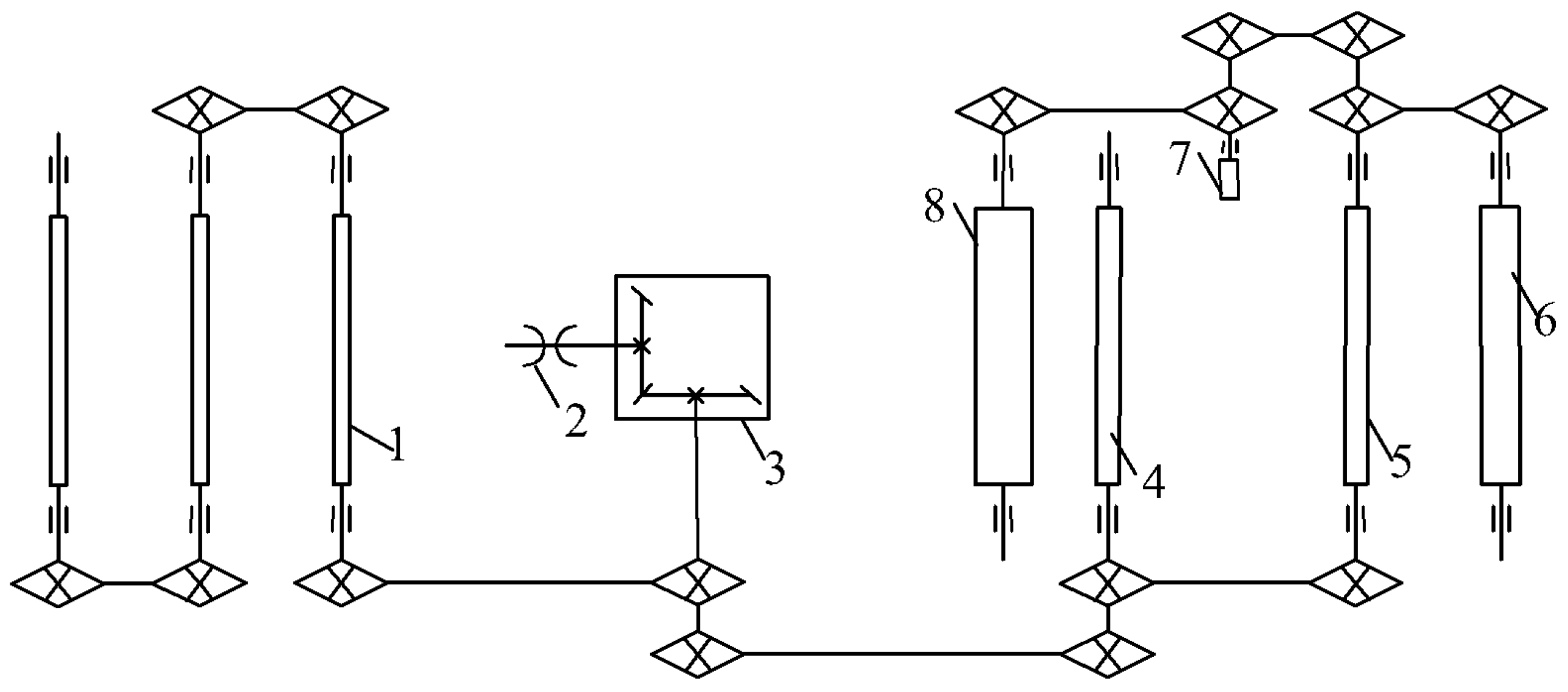
The transmission system of the Astragalus digger employs predominantly chain transmission, and is illustrated in Figure 16. The tractor conveys power to the digger’s gearbox, which changes the transmission direction. Power is sequentially transmitted to the front roller screen and the rear conveyor chain, facilitating the functions of digging, transportation, and cleaning.
The rated speed of the tractor engine power-output shaft is 540 rpm, and the speed of each sprocket in the chain drive is calculated with
n τ n σ = Z σ Z τ
where n τ is the speed of driving wheel (r/min); n σ is the speed of driven wheel (r/min); Z σ is the teeth number of the driving sprocket; and Z τ is the teeth number of the driven sprocket.
Among them, the gear on the output shaft of the gearbox which is matched with the first-stage conveying device has 10 teeth. The number of teeth on the sprocket of the first-stage conveying drive shaft is 27. The number of teeth on the gear of the second-stage conveying device is 9, and the number of teeth on the gear of the second-stage conveying drive shaft is 10. Based on the number of teeth in the sprocket and the speed of the power-conveying shaft, the speed of the driving shaft of the first-stage conveying device is calculated as 193 rpm, while the speed of the driving shaft of the second-stage conveying device is 174 rpm. Given the speed of the driving shaft, the linear speed of the conveyor chain can be calculated with the following:
v d = n τ × 2 π r τ
where v d is the linear speed of the conveyor chain (mm/min), and r z is the radius of the driving wheel (mm).
Among them, the radius of the driving wheel of the first- and second-stage conveying devices is 110 mm. The calculated linear speed of the first-stage conveying device is 2.2 m/s, and the linear speed of the second-stage conveying device is 2 m/s. To ensure the normal operation of the conveying process, it is necessary to meet the requirement that the linear velocity of the soil–Astragalus mixture on the screen is greater than the horizontal-separation velocity on the screen when the unit moves forward [27], that is:
v d > v T cos θ 1
According to Formula (28), the linear speed of the first-stage conveyor chain is 2.2 m/s, and the linear speed of the second-stage conveyor chain is 2 m/s. The horizontal angle between the first- and second-stage conveyor chains and the ground is 30°, and the speed at which the tractor drives the digger forward is 0.5 to 1.5 m/s. Both levels of conveyor screens meet the conveying requirements.

4. Field Experiment

4.1. Test Conditions

Figure 17 is a schematic diagram of the cultivation mode of Astragalus membranaceus according to agronomic requirements. The width of the ridge is 200 mm, the ridge body is 400 mm, and its height is 60~80 mm. The oblique planting angle of the seedlings is 15°, and the plant spacing is 58~60 mm. Black-plastic mulch film with a width of 400 mm and a thickness of 0.01 mm is used to cover the ridge.
To verify the feasibility of the machine’s operation, a prototype performance test was conducted at the Astragalus membranaceus Experimental Base of the Sanniu Agricultural Machinery Company in Dingxi City, Gansu Province. The experimental variety was Longxi Astragalus membranaceus and the experimental field area was 1.24 acres. The terrain was flat, and the soil was fertile and loose. The experimental field was tested, and had a moisture content of about 19% and a surface temperature of 15 °C. The main equipment included an Astragalus digger and Dongfanghong LX904 tractor—see Figure 18.

4.2. Experimental Methods

The main purpose of this experiment was to test the performance of the digger, by measuring the bright-stem rate, loosening rate, and damage rate. Also tested were the working performance of components such as the digger shovel, roller screen and conveyor chain.
A harvest area of 50 m in length and 10 m in width was randomly select at the experimental site. During the experiment, two round-trips were measured, with three randomly selected areas for each trip. Each area had a length of 4 m and a width equal to the width of the machinery operation. After five repeated experiments, different experimental data were obtained and averaged. The performance of the Astragalus digger was tested in accordance with the industry standard NY/T 3481-2019 “Rhizome Chinese medicinal materials harvesters technical specification of quality evaluation” of the People’s Republic of China” [28].
According to the agronomic requirements for harvesting Astragalus, when the bright-stem rate exceeds 90%, it can be regarded as qualified. When the digging and loosening rate exceeds 95%, it can be regarded as qualified. When the damage rate is less than 5%, it can be regarded as qualified.
The calculation formulas for the bright-stem rate (T1), digging and loosening rate (T2), and damage rate (T3) were as follows:
T 1 = M 1 M × 100 %
T 2 = M 2 M × 100 %
T 3 = M 3 M × 100 %
where M 1 is the mass of bright stem (kg); M 2 is the mass of loose roots and stems for digging (kg); M 3 is the mass of damaged roots and stems (kg); and M is the total rhizome mass collected by the digger, i.e., M = M 1 + M 2 + M 3 (kg).
The test results obtained from the above formula are summarized in Table 4.

4.3. Discussion of Test Results

During the field experiment, the prototype was able to complete the experimental indicators in one passage at forward speeds of 0.7, 1.0, and 1.3 m/s. The roller-screen speed was set to 130, 150, and 170 rpm. For a constant forward speed of the implement, the higher the speed of the roller screen, the higher the bright-stem rate and damage rate. After the rotational speed of the roller screen increased, its contact frequency with the mixture increased, and the soil blocks were broken and separated. However, it also increased the contact frequency of Astragalus on the roller screen, leading to an increase in damage rate. When the rotational speed of the roller screen remained constant, the stem rate gradually decreased with the forward speed of the machine, and the damage rate increased with the forward speed of the machine. This indicates that when the forward speed of the machine increased within a certain range, the impulse received by Astragalus increased, leading to an increase in the damage rate. The quality of the soil and medicine mixture excavated per unit time increased, causing the roller screen to enter the conveyor chain directly without enough time for soil and medicine separation, resulting in a reduced rate of bright stems. When the forward speed and the rotational speed of the roller screen changed, the change in the digging and loosening rate was not significant, indicating that the impact on the digging and loosening rate was not significant.
When the forward speed of the machine remained constant and the rotation speed of the roller screen was between 130 and 150 rpm, there was not much difference in the damage rate of Astragalus. However, when the rotation speed of the roller screen was increased to 170 rpm, there was a significant change in the damage rate. When the speed of the roller screen remained constant and the forward speed of the machine was 1.0 m/s, the bright-stem rate was significantly higher than the forward speed of 0.7 m/s, but the difference was not significant compared to 1.3 m/s. It can also be concluded from the field test results that when the forward speed of the prototype was 1.0 m/s and the rotational speed of the roller screen was between 130 and 150 rpm, the operational performance of the equipment was optimal.
A comparative experiment was conducted on the Astragalus digger with a roller screen and soil-crushing device installed, and an improvement has been recorded. The forward speed of the equipment was 1 m/s, while the roller-screen speed was 140 rpm. The data on the bright-stem rate, digging and loosening rate, and damage rate were recorded, and are given in Table 5.
According to the data in this table, it can be seen that the improved model meets the design requirements for the indicators of bright-stem rate, digging and loosening rate, and damage rate. The bright-stem rate increased from 94.06% to 96.26%, and the digging and loosening rate increased from 96.9% to 97.42%. The change in damage rate was not significant, as the roller screen can cause damage to Astragalus during operation. Due to the installation of soil-crushing rollers, the impact of soil blocks on Astragalus during landing is reduced, so the change in injury rate was not significant. In summary, the harvesting quality of the Astragalus digger equipped with roller screens and soil-crushing rollers has been noticeably improved compared to the original model.

5. Conclusions

(1)
According to the agronomic requirements of Astragalus membranaceus harvesting, an Astragalus digger was designed, with a production efficiency of 0.28~0.45 hm2/h for the entire machine. For an equal number of workers, its productivity was 5–6 times higher than the productivity of manual operations. The operational process of the entire machine was simple, reducing labor intensity and improving production. During the harvesting process of Astragalus membranaceus, the soil blocks were crushed, which solved the current problem of crushing the soil after the Astragalus harvest is completed.
(2)
Using EDEM 2020 software, the motion of the roller screen of the equipment was simulated, and it was found that when equipped with a roller screen, the equipment can effectively separate the soil and reduce the conveying resistance. The best installation angle of the conveyor chain has been determined to be 30°. In addition, flexible screens have been installed to reduce vibration damage to Astragalus and to maintain structural integrity. The diameter of the soil-crushing roller was determined to be 160 mm, and the operating width was 1100 mm.
(3)
The field-test results show that the prototype can complete the test indicators in one go when the forward speed of the equipment is 0.7, 1.0, and 1.3 m/s, with the roller screen speed set to 130, 150, and 170 rpm. When the forward speed of the implement remains unchanged and the speed of the roller screen is increased to 170 rpm, the damage rate exceeds 3%. When the speed of the roller screen remains constant and the forward speed of the prototype is 1.0 m/s, the bright-stem rate is better than the forward speed of 1.3 m/s, but the difference is not significant compared to 0.7 m/s. Therefore, when the forward speed of the prototype is 1.0 m/s and the roller-screen speed is between 130 and 150 rpm, the operational performance is optimal.
(4)
Comparative field experiments were conducted between the improved Astragalus digger equipped with roller screen and soil-crushing roller, and the equipment without the roller screen and soil-crushing roller. Test results indicate that the improved equipment has increased the bright-stem rate by about 4%, the digging and loosening rate by 97.42%, and the damage rate by 2.44%. Overall, the equipment meets the design requirements, and provides a significant improvement in performance.

Author Contributions

Conceptualization, W.S. and M.Z.; software, J.D. and P.A.S.; investigation, J.D., W.S., M.Z. and J.W.; resources, W.S. and P.A.S.; writing—original draft preparation, J.D.; writing—review and editing, W.S., P.A.S., M.Z., J.W. and J.D.; supervision, M.Z., J.W. and P.A.S.; project administration, W.S.; funding acquisition, W.S. All authors have read and agreed to the published version of the manuscript.

Funding

This research was funded by the Key Scientific and Technological Program of Gansu Province (22ZD6NA046), the Modern Silk Road Cold and Drought Agricultural Technology Support Project (GSLK-2022-12), Gansu Province Agricultural Machinery Equipment Shortcomings Action Project (njyf2023-13-1) and the Gansu Provincial University Industry Support Plan (2022CYZC-42).

Institutional Review Board Statement

Not applicable.

Informed Consent Statement

Not applicable.

Data Availability Statement

Data are reported within the article.

Conflicts of Interest

The authors declare no conflicts of interest.

References

  1. Zhou, S.; Wu, W.; Guo, L.; Yang, S.; Zhao, L.; Zhi, H.; Liu, Z.; Yang, X. Changes in China’s Astragalus membranaceus production areas and the development process of cultivation industry. Mod. Chin. Med. 2023, 25, 2428–2433. [Google Scholar]
  2. Wang, X.; Shi, L.; Wei, Q.; Liu, X.; Shang, H.; Leng, Y. Production Technology Model of Reducing Application and Increasing Efficiency of Astragalus membranaceus Chemical Fertilizer and Pesticide in Dingxi City, Gansu Province. China Agric. Technol. Promot. 2021, 37, 38–40. [Google Scholar]
  3. Xu, Y.; Wang, F.; Zhang, F.; Yang, Y.; Song, X.; Dai, F.; Zhang, F. Design and simulation analysis of the separation screen of Astragalus digger. Agric. Equip. Veh. Eng. 2020, 58, 1–4. [Google Scholar]
  4. Yang, H.; Cao, M.; Wang, B.; Hu, Z.; Xu, H.; Wang, S.; Yu, Z. Design and Test of a Tangential-Axial Flow Picking Device for Peanut Combine Harvesting. Agriculture 2022, 12, 179. [Google Scholar] [CrossRef]
  5. Liu, X.; Li, L.; Qi, J.; Meng, H.; Li, Y.; Sun, X.; Lin, Y. Design and Experiment of Potato Harvester. Jiangsu Agric. Sci. 2019, 47, 242–247. [Google Scholar]
  6. Li, K. Research on Key Technologies of Self-Propelled Carrot Combine Harvester; China Academy of Agricultural Mechanization Sciences: Beijing, China, 2015. [Google Scholar]
  7. Shahgoli, G.; Fielke, J.; Desbiolles, J.; Chris, S. Optimising Oscillation Frequency in Oscillatory Tillage. Soil Tillage Res. 2010, 106, 202–210. [Google Scholar] [CrossRef]
  8. Fan, K. Design and Key Mechanism Simulation Analysis of Licorice Harvester; Gansu Agricultural University, Gansu, China, 2018.
  9. Zhang, X.; Zhang, X.; Qiao, F. Crop Rhizome or Underground Fruit Harvester. CN2686291, 23 March 2005. [Google Scholar]
  10. Li, T.; Zhou, J.; Xu, W.; Zhang, H.; Liu, C.; Jiang, W. Design and Experiment of Automatic Rowing System for Rootstock Crop Harvesters. Trans. Chin. Soc. Agric. Mach. 2019, 50, 102–110. [Google Scholar]
  11. Chen, X.; Ma, X.; Chen, G.; Qi, L.; Wu, T.; Zeng, L. Research on the Root Soil Separation Device for Deep Rooted and Stem Chinese Medicinal Materials. Mach. Des. 2015, 32, 65–70. [Google Scholar]
  12. She, Z.; Bai, X. Two-Stage Conveying Hard Suspended Licorice Digger. CN201781773U, 6 April 2011. [Google Scholar]
  13. Yang, F.; Yang, Y.; Li, W.; Zhao, G.; Jiang, F.; Li, J. Design and experiment of vibration digging and soil crushing device for suspended yam harvester. Trans. Chin. Soc. Agric. Mach. 2020, 51, 104–111. [Google Scholar]
  14. Wan, L.; Li, Y.; Zhang, C.; Ma, X.; Song, J.; Dong, X.; Wang, J. Performance Evaluation of Liquorice Harvester with Novel Oscillating Shovel-Rod Components Using the Discrete Element Method. Agriculture 2022, 12, 2015. [Google Scholar] [CrossRef]
  15. Yang, X.; Wei, H.; Zhao, W.; Jiang, Y.; Dai, L.; Huang, X. Design and Test of 4U1600 Stacking Potato Digger. Trans. Chin. Soc. Agric. Mach. 2020, 51, 83–92. [Google Scholar]
  16. Zhen, D.; Zhao, M.; Chen, G.; Zhang, X. Design of the 4SB-800 Pinellia Harvester. Trans. Chin. Soc. Agric. Eng. 2007, 10, 141–144. [Google Scholar]
  17. Zhang, D.; Zhang, J.; Liu, X.; Qin, X.; Li, Q.; Min, L.; Ren, D.; Zhang, C. Design of 4CZ-1 type caterpillar self propelled integrative machine for scallion harvesting. J. Agric. Mech. Res. 2022, 44, 71–79. [Google Scholar]
  18. Zhang, D.; Zhang, Z.; Gao, Y.; Wang, F. Design and experiment on combined digging shovel of Panax notoginseng harvester. J. Jiangsu Univ. Nat. Sci. Ed. 2018, 39, 38–44. [Google Scholar]
  19. Bentine, M.; Caprarac, C.; Martelli, R. Harvesting damage to potato tubers by analysis of impacts recorded with an instrumented sphere. Biosyst. Eng. 2006, 94, 75–85. [Google Scholar] [CrossRef]
  20. Lv, J.; Tian, Z.; Yang, Y.; Shang, Q.; Wu, J. Design and Experiment of 4U2A Double row Potato Digger. Trans. Chin. Soc. Agric. Eng. 2015, 31, 17–24. [Google Scholar]
  21. Xie, X. Design and Experimental Research of Licorice Harvester; Xinjiang Agricultural University: Xinjiang, China, 2014. [Google Scholar]
  22. Feng, X.; Wang, L.; Yu, K.; Gao, Y.; Bi, C.; Wang, B. Design and Experiment of Wave Screen Mechanism for Cleaning Corn Grains. Trans. Chin. Soc. Agric. Mach. 2023, 54, 142–154. [Google Scholar]
  23. Shi, B.; Sun, W.; Zhao, Z.; Wang, H.; Zhang, L.; Zhang, H.; Li, H.; Liu, X.; Liu, P. Design and Experiment of the Combined Machine for Transplanting Outcrop of Codonopsis with Micro Ridge Covered with Film. Appl. Sci. 2023, 13, 9149. [Google Scholar] [CrossRef]
  24. Zhang, Z.; Xue, H.; Wang, Y.; Xie, K.; Deng, Y. Design and Experiment of Sanqi Biomimetic Excavator Based on Discrete Element Method. Trans. Chin. Soc. Agric. Mach. 2022, 53, 100–111. [Google Scholar]
  25. Ren, S. Design and Experiment of Soil Crushing Digging Device for Potato Harvesters in Hilly and Mountainous Areas; Sichuan Agricultural University: Sichuan, China, 2021. [Google Scholar]
  26. Zhang, Z.; Wang, H.; Li, Y.; Yang, X.; Ibrahim, I.; Zhang, Z. Design and Experiment of Multistage Separation Buffer Potato Harvester. Trans. Chin. Soc. Agric. Mach. 2021, 52, 96–109. [Google Scholar]
  27. Sun, W.; Wang, H.; Zhao, W.; Zhang, H.; Liu, X.; Wu, J. Design and experiment of potato digger with waste film recollection for complete film mulching, soil covering and ridge sowing pattern. Trans. Chin. Soc. Agric. Mach. 2018, 49, 105–114. [Google Scholar]
  28. NY/T 3481-2019; Rhizome Chinese Medicinal Materials Harvesters Traditional Specification of Quality Evaluation. Ministry of Agriculture and Rural Affairs of the People’s Republic of China: Beijing, China, 2019.
Figure 1. Main components of the machine: 1. Digger blade. 2. Roller screen. 3. First-stage conveyor-chain drive shaft. 4. Travelling wheel. 5. Second-stage conveyor-chain drive shaft. 6. Medicine collection boxes. 7. Soil-crushing roller. 8. Second-stage conveyor chain. 9. Crushed-soil roller. 10. Lifting bracket. 11. First-stage conveyor chain. 12. Gearbox. 13. Suspension device.
Agriculture 14 00701 g001
Figure 2. Digging-shovel components. 1. Digging shovel. 2. Support frame. 3. Shovel-frame connection plate. 4. Adjusting nut.
Agriculture 14 00701 g002
Figure 3. Diagram of force acting on the digger shovel.
Agriculture 14 00701 g003
Figure 4. Schematic diagram of roller screen. 1. Left-drive chain. 2. Power-input chain. 3. Right-drive chain.
Agriculture 14 00701 g004
Figure 5. Force-analysis diagram of the roller screen.
Agriculture 14 00701 g005
Figure 6. DEM simulation (a) without and (b) with the roller screen installed: 1. Soil particles. 2. Soil-particle bed. 3. Roller screen. 4. Conveyor chain.
Agriculture 14 00701 g006
Figure 7. Steady-state DEM simulation without a screen (a) and detail of conveyor-chain particle effect (b).
Agriculture 14 00701 g007
Figure 8. Steady-state DEM simulation with a roller screen (a) and detail of conveyor chain particle effect (b).
Agriculture 14 00701 g008
Figure 9. Particle-number measurement at different stages.
Agriculture 14 00701 g009
Figure 10. Structure diagram of two-stage separation conveyor chain: (a) side view and (b) axonometric view. 1 and 2 are the front wheels of the first- and second-stage conveyor chains, 3 is the small soil blocks, 4 and 5 are the rear wheels of the first- and second-stage conveyor chains, 6 is the large clod, and 7 is the Astragalus plants.
Agriculture 14 00701 g010
Figure 11. Force analysis of Astragalus as it moves on the conveyor.
Agriculture 14 00701 g011
Figure 12. Pictures of the physical prototype (a) and rod detail (b).
Agriculture 14 00701 g012
Figure 13. Diagram of the soil-crushing roller. 1. Drive shaft. 2. Reinforced disc. 3. Fastening ring.
Agriculture 14 00701 g013
Figure 14. Diagram of Astragalus movement at the end of the conveyor chain.
Agriculture 14 00701 g014
Figure 15. Diagram of soil crushing roller. 1. Conveyor device. 2. Large clod. 3. Crushed-soil roller. 4. Connection board. 5. Support frame. 6. Small soil blocks.
Agriculture 14 00701 g015
Figure 16. Digger transmission diagram. 1. Roller-screen shaft. 2. Power-input shaft. 3. Gearbox. 4. First-stage conveyor-chain drive shaft. 5. Second-stage conveyor-chain drive shaft. 6. Crushed-soil roller shaft. 7. Fixed-gear shaft. 8. Crushed-soil roller shaft.
Agriculture 14 00701 g016
Figure 17. Diagram of Astragalus membranaceus agronomic cultivation mode. 1. Root of Astragalus. 2. Head of Astragalus. 3. Ridge body. 4. Membrane-covered soil zone. 5. Furrow. 6. Black plastic film. 7. Outcrop area on membrane side.
Agriculture 14 00701 g017
Figure 18. Field-test photographs.
Agriculture 14 00701 g018
Table 1. Main technical parameters of operating machine.
ParametersNumerical Values
Machine dimensions
(length × width × height)
3146 × 1953 × 1570 (mm)
Auxiliary power44.1 kw
Working width1360 mm
Suspension modeThree-point suspension
Digging depth (adjustable) 200~400 mm
Table 2. Parameters of simulation model.
ProjectParametersNumerical Value
Soil particlesPoisson’s
Ratio shear modulus/Pa
Density/(kg.m−3)
0.4
1.0 × 10⁶
1364
Roller screenPoisson’s
Ratio shear modulus/Pa
Density/(kg.m−3)
0.28
3.5 × 10¹⁰
7850
Soil particles–soil particlesCoefficient of recovery
Coefficient of static friction
Coefficient of dynamic friction
0.21
0.68
0.27
Soil particles–roller screenCoefficient of recovery
Coefficient of static friction
Coefficient of dynamic friction
0.54
0.68
0.13
Table 3. Particle-count statistics for two different devices at different time periods.
ProjectTimes (s)The Number of Soil Particles (n)Total Number of Soil Particles (n)
Q 1 620188201
72205
82192
92386
Q 2 6452918,753
74603
84746
94875
Table 4. Results of field test.
NumberForward Speed (m/s)Roller-Screen Speed (r/min)Bright-Stem Rate (%)Digging and Loosening Rate (%)Damage Rate (%)
10.713095.596.92.3
20.715095.296.52.6
30.717097.897.13.1
41.013095.397.82.0
51.015096.498.32.1
61.017097.797.53.2
71.313093.298.02.3
81.315095.198.92.4
91.317096.798.23.6
Table 5. Statistical table of relevant data of the harvest quality of the models before and after improvement.
NumberMachinery before ImprovementMachinery after Improvement
Bright-Stem Rate (%)Digging and Loosening Rate (%)Damage Rate (%)Bright-Stem Rate (%)Digging and Loosening Rate (%)Damage Rate (%)
194.696.32.596.597.12.4
293.897.52.395.396.82.1
394.098.01.997.398.22.6
493.596.52.896.897.93.1
593.996.22.496.497.12.0
Average value (%)93.9696.92.3896.4697.422.44
Disclaimer/Publisher’s Note: The statements, opinions and data contained in all publications are solely those of the individual author(s) and contributor(s) and not of MDPI and/or the editor(s). MDPI and/or the editor(s) disclaim responsibility for any injury to people or property resulting from any ideas, methods, instructions or products referred to in the content.

