Article

Study on Agricultural Machinery-Load-Testing Technology and Equipment Based on Six-Dimensional Force Sensor

Nanjing Institute of Agricultural Mechanization, Ministry of Agriculture and Rural Affairs, Nanjing 210014, China
*
Author to whom correspondence should be addressed.
Agriculture 2023, 13(9), 1649; https://doi.org/10.3390/agriculture13091649
Submission received: 28 July 2023 / Revised: 18 August 2023 / Accepted: 19 August 2023 / Published: 22 August 2023
(This article belongs to the Special Issue Sensor-Based Precision Agriculture)

Abstract

:
Tractor traction power consumption is one of the main causes of energy consumption in agricultural production. Scientific and accurate control of tractor traction power consumption can obviously save energy and reduce consumption. In view of the backward load-testing technology and low measurement accuracy in field work, this study designed an array test equipment, which formed a measurement matrix based on a six-dimensional force sensor to accurately measure tractor hauled load, which could provide a reference signal for intelligent operation. In this paper, the static calibration test was carried out on the six-dimension force sensor, and the linearity, sensitivity, and zero drift were analyzed. The static characteristics of the test unit meet the measurement requirements. A static decoupling model was established. The decoupling errors of each channel were stable at 0.02%FS, 0.02%FS, 0.8%FS, 0.36%FS, 0.018%FS, and 0.06%FS, respectively. Finally, the whole hanging test of the measuring equipment was carried out—the error was 1.24%, −1.2% respectively—to verify the accuracy of the measurement of the sensor device under different working conditions.

1. Introduction

The tractor is one of the important pieces of agricultural equipment, as it plays an important role in the construction of agricultural modernization. With the continuous advancement of agricultural modernization, scale, and intelligence, high-power tractors have become the main direction of development [1,2,3,4]. Tractor traction power consumption is one of the main reasons for energy consumption in agricultural production; thus, scientific and accurate control of tractor traction power consumption can obviously play a role in energy saving and consumption reduction [3,5,6,7]. To carry out high-power tractor operation load tests, accurate and real-time acquisition of traction signals is the premise of accurate control of tractor traction power consumption [4].
On the one hand, due to different soil conditions and operation needs, when the tractor is suspended with different agricultural equipment, the unit operation and transmission parts will continue to be subjected to soil reaction [8,9,10]. On the other hand, many farmers, in order to reduce the operating cost of machinery and the damage of agricultural machinery to farmland, often choose compound multifunction machinery, which leads to a huge increase in the entire operating unit shape, increase in weight, structural asymmetry, and a greater imbalance of inertia force. Therefore, the tractor working load has the characteristics of continuity and uncertainty, which increases the difficulty of testing it [11,12,13].
Tractor operating-load-testing methods mainly consist of car-pulling, octagonal ring, in-place method, force pin method, and so on. These methods have obvious measurement limitations. If the operating parameters of the machine are increased greatly, the interference that is originally ignored will be amplified infinitely [14,15,16,17]. The key to improve the measurement accuracy of space load from agricultural power unit is to keep the original suspension structure unchanged and the load transfer characteristics without changing the original structure. In view of the above situation, a dynamic load transfer structure based on suspension structure was developed abroad to measure the operating load without changing the original structure [18,19,20]. In 2015, Jordi Pijuan et al. designed a “two-layer” measuring mechanism to measure traction and vertical force. This measuring mechanism could also be configured with a six-dimensional force sensor for measurement, but because of the lack of relevant theoretical research basis, only a bidirectional force sensor was configured [21,22,23,24]. In 2020, Yeon-Soo Kim et al. also designed a “two-layer” type measurement rack configured with six unidirectional force-sensing units in the middle to, respectively, measure traction force, vertical force, and lateral force, and the authors also designed a tillage-depth-measuring mechanism at the same time so that the two kinds of data could be mutually verified [25,26,27]. The measuring mechanism did not change the original load transfer characteristics; the measured data were more accurate, but there were still obvious defects: (1) the structure of the measuring mechanism was complicated, which increased the tractor suspension load; and (2) torque interference could not be excluded, that is, the sensor coupling caused by torque could not be eliminated, so it could not adapt to the operation process with eccentric force.
In this paper, aiming at problems such as heavy load, measurement difficulty in the process of agricultural machinery operation, and poor linear difference between input and output, the dimensional coupling of existing six-dimensional force sensors for heavy loads as an array of measuring equipment with six-dimensional force sensors as measuring units was designed, which can be directly connected to tractors and agricultural machinery, ensuring constant load transfer to improve measurement accuracy. Our team completed the design of a six-dimensional force sensor suitable for heavy load measurement that was mounted on the device but did not complete the analysis of the static performance, so the reliability of the test results cannot be guaranteed. This paper mainly studies the working principle of the measuring equipment and the static characteristics of the six-dimensional force sensor by the method of indoor hanging and static calibration test [28,29]. The research results provide a technical basis for testing equipment systems and agricultural machinery intelligent equipment, greatly improve the independent innovation ability of agricultural equipment research and development in China, and have great significance in accelerating the development of intelligent agricultural machinery equipment technology, narrowing the gap with foreign mainstream products and promoting the development of modern agriculture [30,31].

2. Materials and Methods

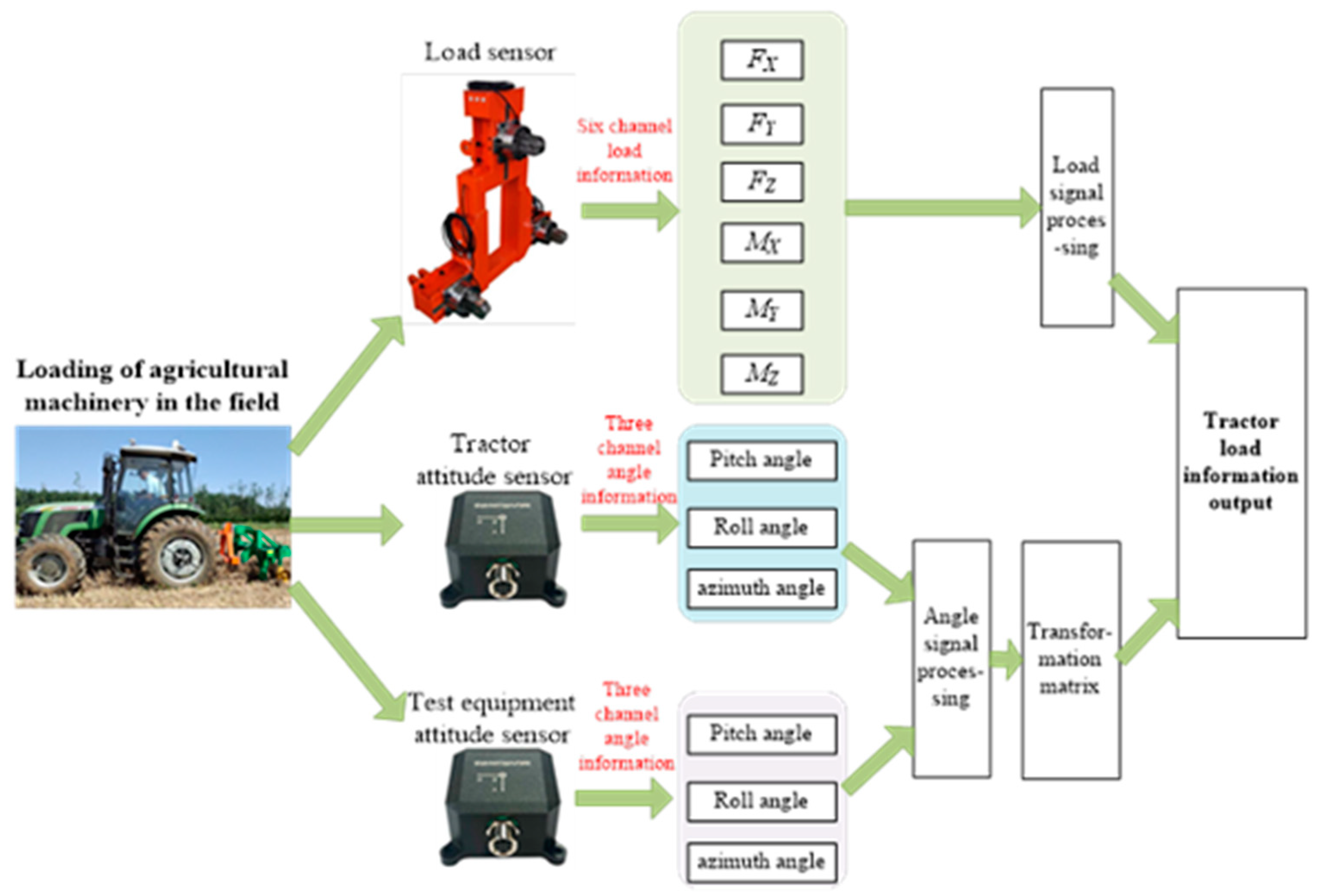
2.1. Design of Load Test Scheme for Whole Machine Operation

2.1.1. Test Procedure Introduction

The array test equipment was installed in the middle of the tractor and agricultural equipment, and two angle sensors were installed on the tractor and test equipment to, respectively, measure their pitch angle, roll angle, and azimuth angle. When the working unit started working, the working load of the machine tool was measured by the array device. The angle information of the tractor and the test equipment was measured by the angle sensor, and the spatial transformation matrix for the working load of the tractor and the test equipment was established by the angle information. Finally, the load measured by the equipment and the space transformation matrix were used to obtain the resistance of the tractor during operation as shown in Figure 1.
Software (iDAS R&D), as shown in Figure 2, for the sensors support two kinds of communication buses, namely RS232 and Ethernet TCP, with command input window. They support the above WIN7 system, do not support the Linus system, and cannot be installed; after decompression, they must be directly run.

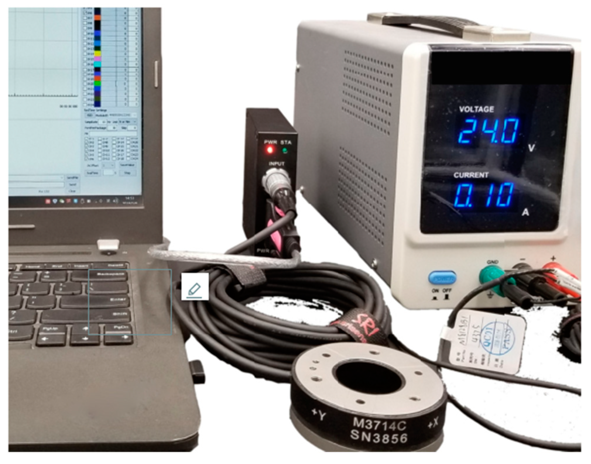
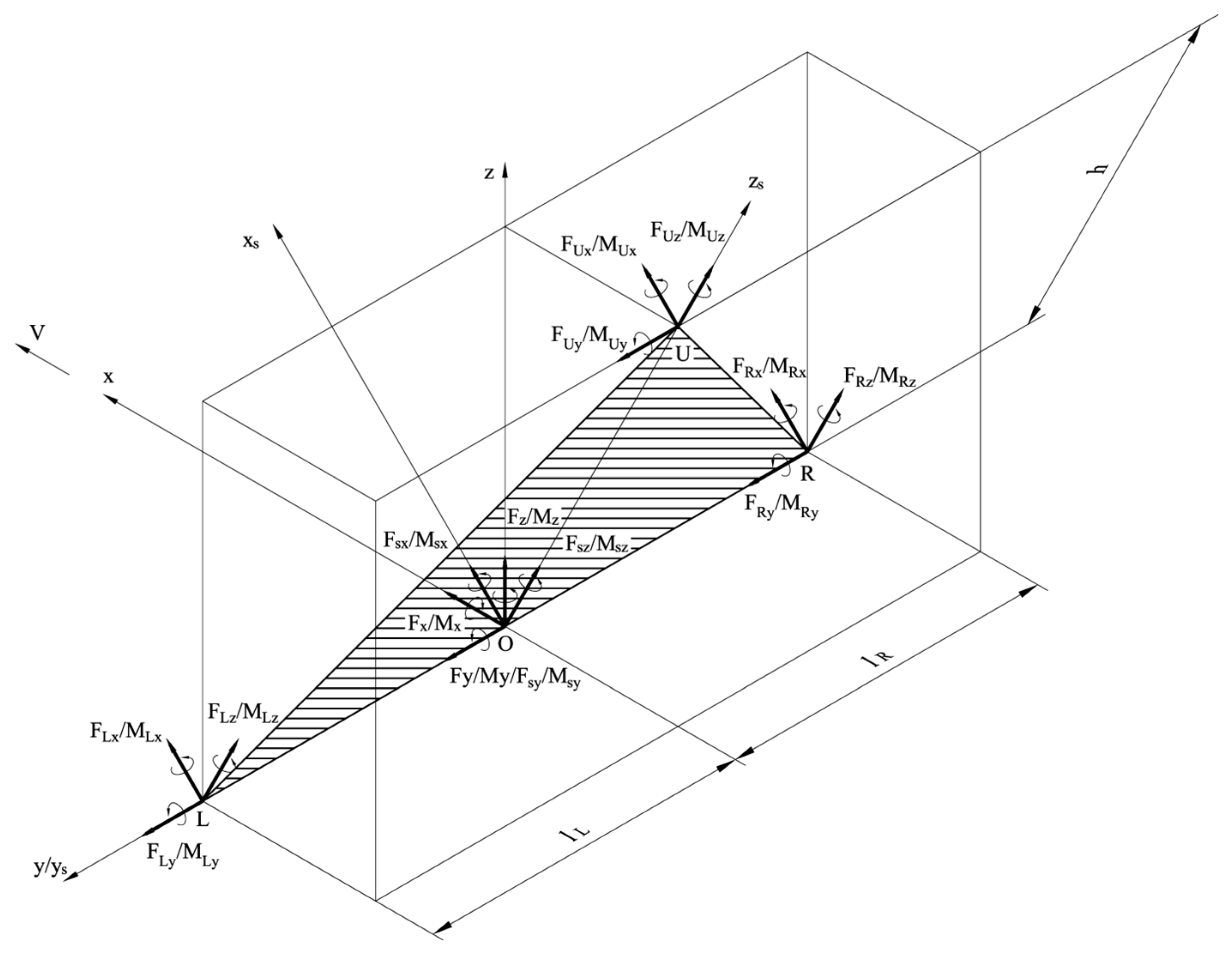
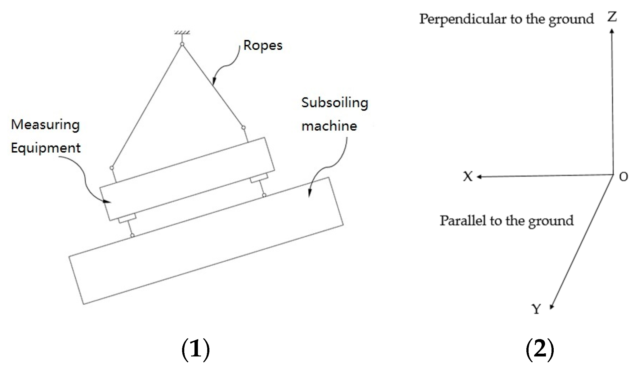
2.1.2. Test Device Connection and Spatial Matrix Derivation

The test equipment was mainly composed of a frame, three six-dimensional force sensors, tilt sensor, signal conditioning module, and connecting parts. The front end of the equipment was hinged with the tractor upper and lower suspension rods, and the back end was hinged with the agricultural machinery at three points, so the whole series was connected between the tractor and the agricultural machinery without changing the original connecting mechanism of the tractor and the agricultural machinery, thereby reducing the risk of increasing the measurement error caused by changing the structure. A strip groove was opened on the frame matrix, which could change the left and right positions of the force sensors to adapt to the suspension size of non-standard agricultural machinery. Three connecting points were arranged on the frame to replace the original suspension points configured with a six-dimensional force sensor, respectively, to form the measurement array, which can simultaneously measure the force ( F x , F y , F z ) and torque ( M x , M y , M z ) in the three directions of the connection. The array-based test scheme is shown in Figure 3.
During the test, the force value acting on the test equipment was directly obtained, which needed to be converted into the actual force on the tractor. The actual load of the tractor was synthesized by the middle point O of the lower suspension point line through the principle of spatial force system change. The mechanical relationship between the measuring equipment and the tractor is shown in Figure 4.
In Figure 4, O x y z is the coordinate system of tractor, with the center point O of the left and right connecting contacts as the coordinate origin; the x -axis points to the forward direction, the y-axis refers to the left, and the z-axis is vertically upward. Oxsyszs is the coordinate system of the sensing device; O is the origin of the coordinates; L, R, and U are, respectively, the lower left contact, lower right contact, and upper contact of the machine. In the Oxsyszs coordinate system, the force on point S is as follows:
F s x = F L x + F R x + F U x F s y = F L y + F R y + F U y F s z = F L z + F R z + F U z M s x = M L x + M R x + M U x F U y h F R z l R + F L z l L M s y = M L y + M R y + M U y + F U x h M s z = M L z + M R z + M U z + F R x l R F L x l L
In Formula (1), F s x , F s y , F s z are the component force of point S in the direction of the x s -axis, y s -axis, and z s -axis; M s x , M s y , M s z are the torque. F L x ,   F R x , F U x , F L y , F R y , F U y , F L z , F R z , F U z are the forces in the direction of the x s -axis, y s -axis, and z s -axis subjected to points L, R, and U. M L x , M R x , M U x , M L y , M R y , M U y , M L z , M R z , M U z are the torque. l R is the distance from R to O, l L is the distance from L to O, and h is the distance from U to O.
Assuming that the angles of the three sensors relative to the tractor are α, β, and γ, respectively, representing pitch angle roll angle and azimuth angle, respectively, the relation matrix of the coordinate system O x y z and Oxsyszs can be obtained according to the principle of space mechanical transformation:
R x α = 1 0 0 0 cos α sin α 0 sin α cos α
R y β = cos β 0 sin β 0 1 0 sin β 0 cos β
R z γ = cos γ sin γ 0 sin γ cos γ 0 0 0 1
F x F y F z M x M y M z = R z γ R y β R x α F s x F s y F s z M s x M s y M s z
F x , F y , F z , M x , M y , M z are the actual load information of the tractor.

2.2. Static Data Acquisition of the Six-Component Force Sensor

The static calibration test of the sensor was carried out on the indoor test bench, and the load was enacted by the loading equipment, which was provided by Guangzhou Guangdian Metrology and Testing Co., Ltd. (Guangzhou, China). All the instruments and equipment used passed the metrology certification and provided accurate load signals. In order to obtain an accurate decoupling model and reduce the difficulty of data processing, each measurement channel was loaded separately, and the data of all channels were collected at the same time. The load was acted from zero, and data were recorded every 50 pounds (220 N) until reaching the full-scale load. The loading process was repeated three times for each channel, while the return data were also recorded to study the hysteresis of the sensor.
Torque loading was adopted according to the mode of eccentric force. The eccentric force on the loading platform could be converted into a force and equivalent torque through mechanical laws. The obtained data were processed to remove the influence of the force generated by transformation. The loading of force and moment is shown in Figure 5.

2.3. Static Data of the Six-Component Force Sensor Acquisition

2.3.1. Method of Linearity Analysis

The linearity of the sensor (nonlinear error) is referred to the linearity relationship between the output and input of the sensor. The ideal output–input relationship should be linear. Most of the sensor characteristics encountered in practice are nonlinear. In order to obtain a better linear relationship, nonlinear compensation is often introduced.
γ L = ± L m a x Y F S × 100 %
In Formula (6), γ L is linearity, and Δ L max is the maximum nonlinear absolute error; Y F S = y max y min is the full-scale output.

2.3.2. Method of Hysteresis Analysis

During the positive (increasing input) and negative (decreasing input) working process of the sensor, the phenomenon that the output–input characteristic curves did not coincide is called hysteresis. The main reason for this phenomenon was the physical properties of the sensor-sensitive element material and the defects of the mechanical parts, such as the elastic hysteresis of the elastic sensitive element, the friction of the moving parts, the clearance of the transmission mechanism, and the loosening of fasteners. Hysteresis γ H is expressed as a percentage of the maximum forward and backward stroke output difference or half of it to the full-scale output.
γ H = ± H m a x Y F S × 100 %   or   γ H = ± H m a x 2 Y F S × 100 %
In Formula (7), Δ H max is the maximum difference of positive and negative working process.

2.3.3. Method of Sensitivity and Zero-Drift Analysis

Sensitivity refers to the ratio of the output change of the sensor under steady state to the input change, which is expressed by k = Δ y Δ x . It characterizes the sensor’s ability to respond to changes to input. To linear sensors, the sensitivity is the static slope, which is a constant, while the sensitivity of nonlinear sensors is a variable, which is expressed by k = d y d x . When the sensor has no input, its output is the zero drift, and its value is as follows: Y 0 Y F S × 100 % ; Δ Y 0 is the maximum zero deviation.

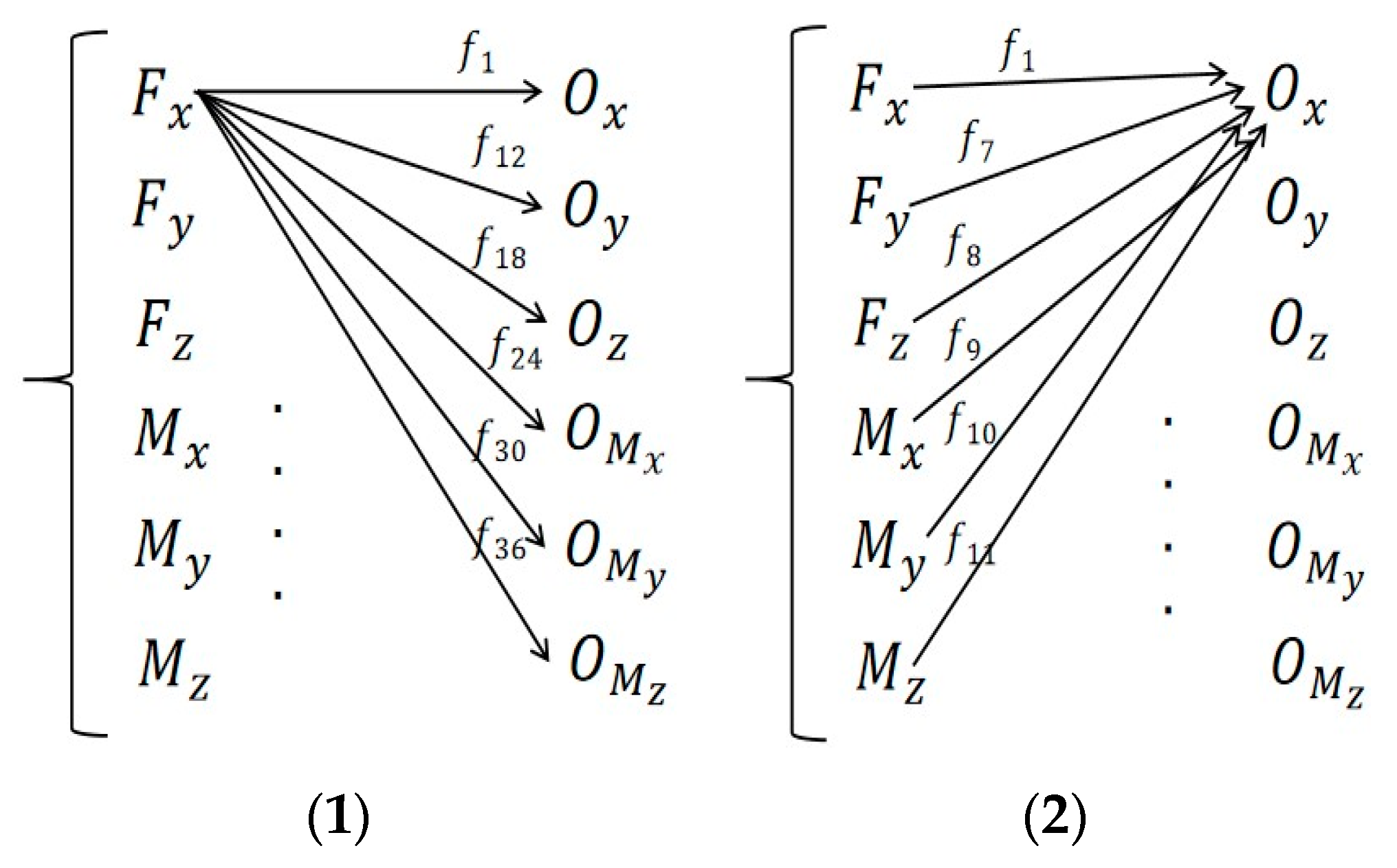
2.3.4. Method of Static Decoupling Analysis

In the field of agricultural machinery, due to the complexity of the working environment, such as sloping land, wet and rotten land, straw, soil imbalance congestion, etc., that would lead the tractor suspension mechanism to be influenced by unbalanced force or torque, real-time adjustment of operation parameters can improve the whole unit operation effect. On the one hand, due to the large operating load, the compact internal structure of the sensor, the processing technology, the patch, the working environment, and the sensor structure itself, the signal of the main measurement channel always interferes with the coupled channel. As shown in Figure 5, the force in one direction causes interference with all measurement channels; that is to say, one measurement channel in each direction always contained the force in all directions. This section uses the original data obtained from the calibration test, establishes a decoupling model, and inputs the electrical signal measured by the sensing device into the decoupling model to obtain the force or moment to reduce coupling interference.
There are many methods for establishing the decoupling model, such as inverse matrix method and least-square method. In this paper, inverse matrix method is used to establish the decoupling model. The relationship in Figure 6 can be written as Formula (8).
O x O y O z O M x O M y O M z = f 1 f 7 f 8 f 9 f 10 f 11 f 12 f 2 f 13 f 14 f 15 f 16 f 17 f 18 f 3 f 19 f 20 f 21 f 22 f 23 f 24 f 4 f 25 f 26 f 27 f 28 f 29 f 30 f 5 f 31 f 32 f 33 f 34 f 35 f 36 f 6 F x F y F z M x M y M z
Formula (9) can be written as Formula (10):
O = KF
In Formula (9), F is the load matrix, K is the coefficient matrix, and O is the output matrix. The Formula (11) can thus be obtained.
F = K 1 O

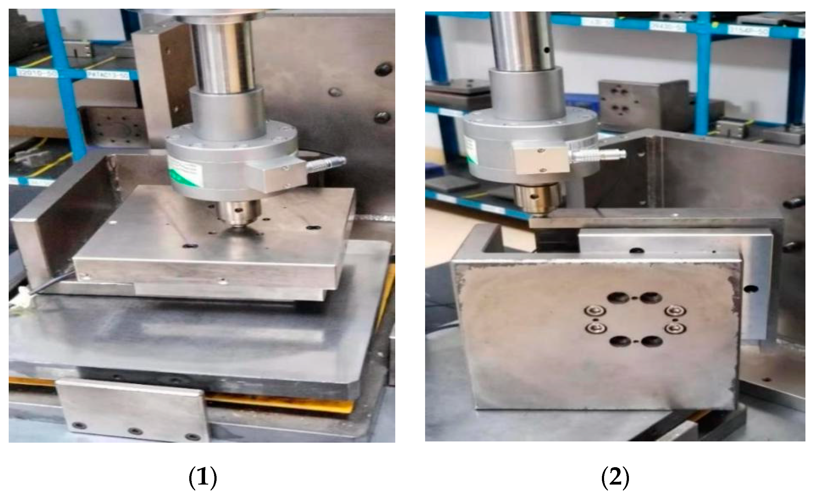
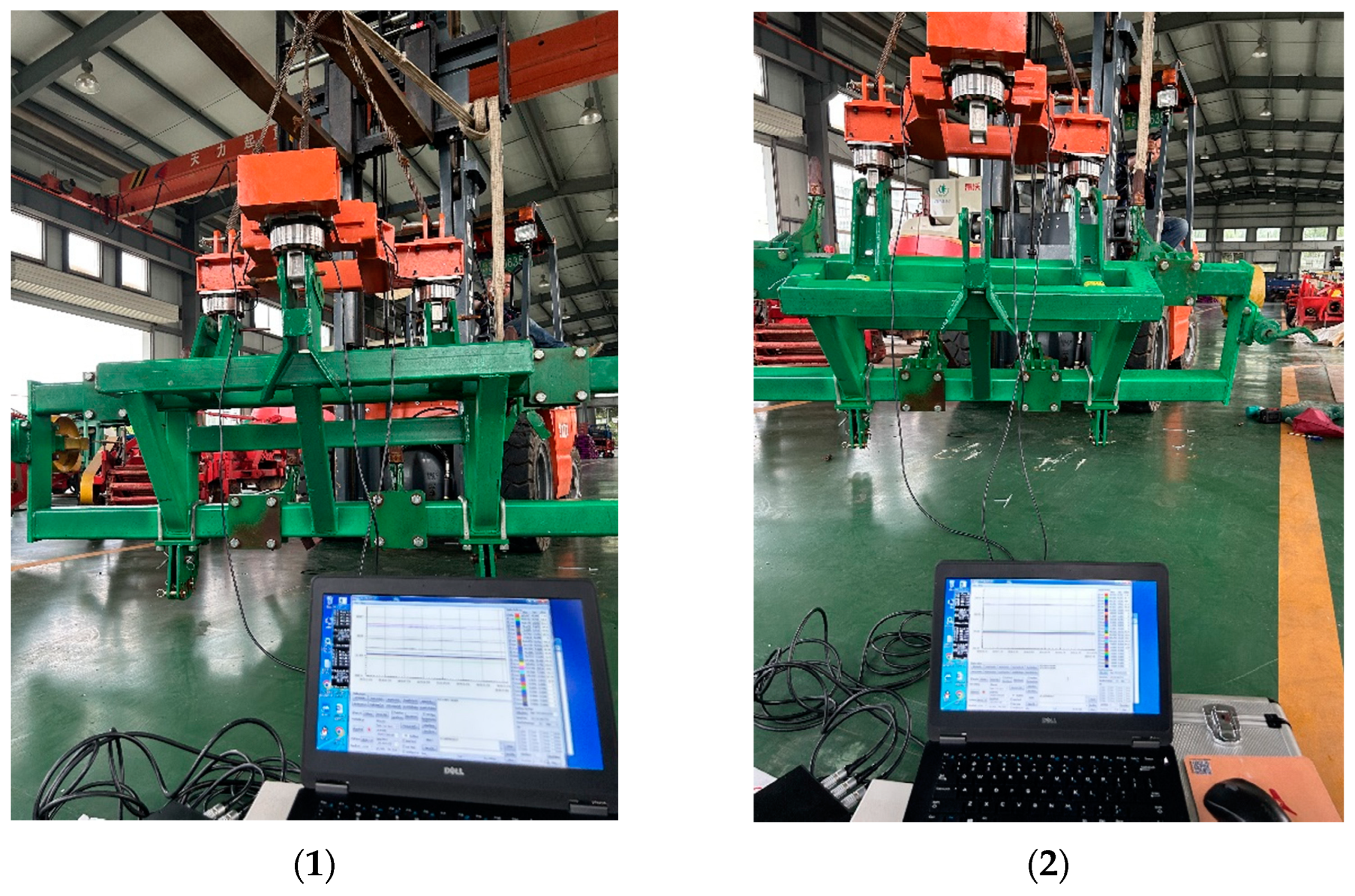
2.4. Integrated Test Research of Array Test Equipment

In order to verify the overall performance of the test equipment, the verification test of “accuracy of measurement of sensing device under different tilt angles” was carried out.
In this test, the weight of the sub-soiling machine was measured to verify that the equipment could work at different tilt angles. It was not necessary to set a fixed angle value; we only needed to use different lengths of rope to place the test device in a non-vertical state as shown in Figure 7.
The main steps were as follows:
(1)
Use electronic hanging scale to weigh out the mass of the sub-soiling machine;
(2)
Set the direction of gravity acceleration of the angle sensor as reset in the software;
(3)
Connect the measuring equipment to the sub-soiling machine and complete the connection work of signal acquisition system;
(4)
Lift equipment and signal acquisition.

3. Results and Discussion

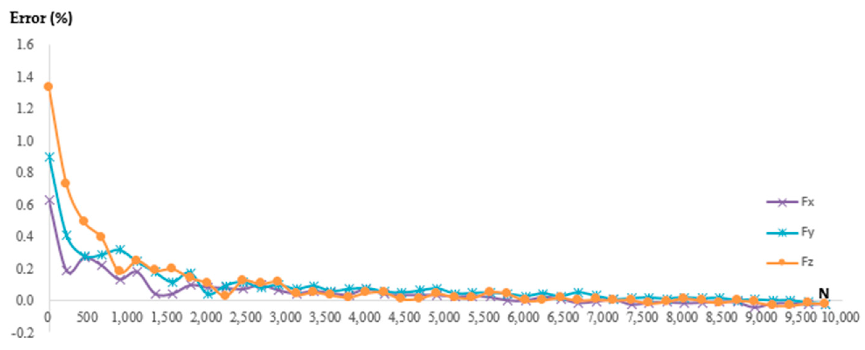
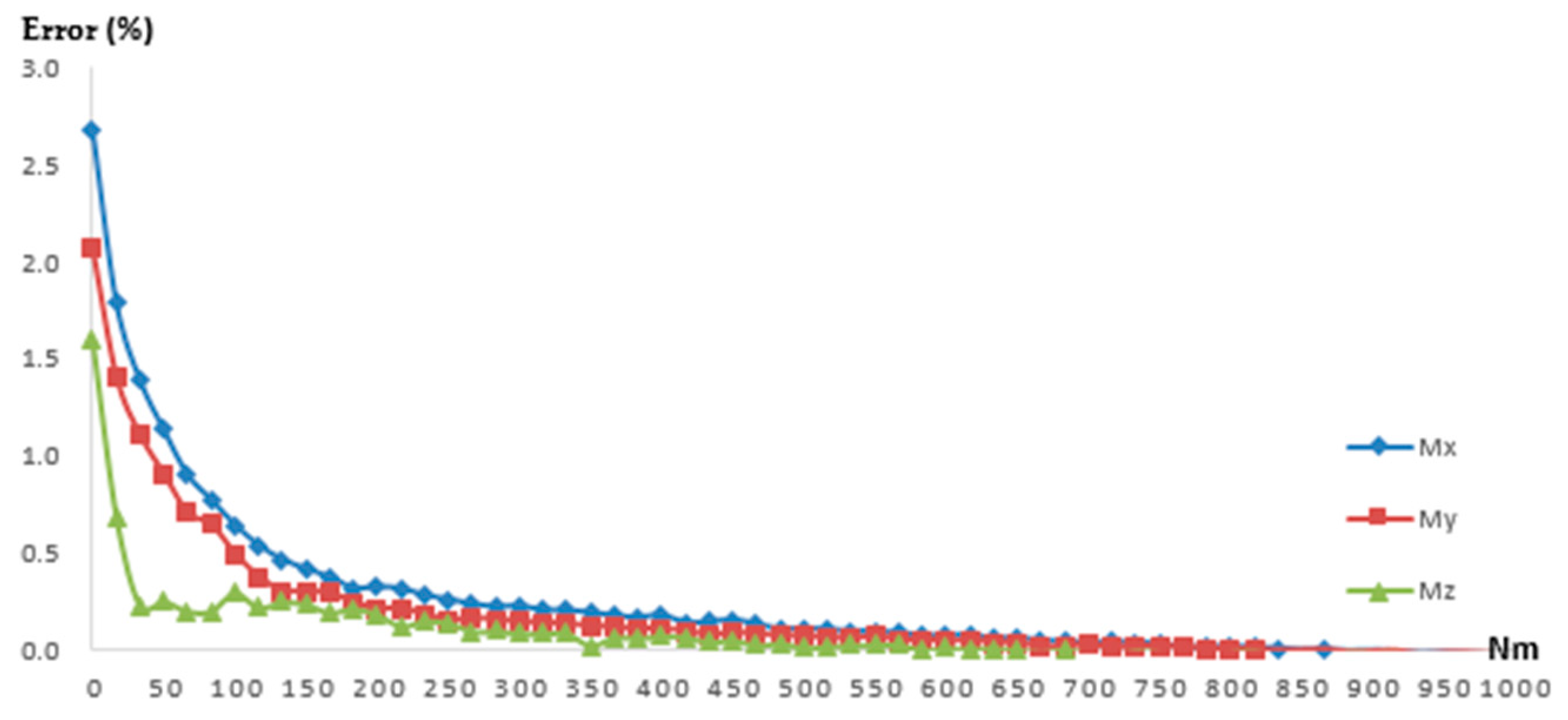
3.1. Results of Input–Output Linear Relationship

In Formula (6), the numerator is the maximum nonlinear error, the denominator is the difference between the maximum and minimum output, and the smaller the value, the better the linearity of the line. It can be seen from the data in Table 1 that when F x , F y , F z , M x , M y , M z are added separately, which capacity is 10,000 N, 1000 N∙m as shown in Table 2, the linearity of the main channel is 0.28, 0.31, 0.38, 0.25, 0.35, and 0.11 as shown in Table 3, respectively, and it can be concluded that the input–output of each measuring main channel had a good linear relationship, ensuring the accuracy of the measurement results.
The coupling output data of the main channel to other channels showed some nonlinearity for the following reasons: (1) The internal structure of the sensor was relatively compact, the spatial distribution distance of the respective strain gauges was small, but the load was large, so it caused greater interference. (2) The structural design and test loading of the sensor mainly served the analysis of the main pass performance, and there was a large randomness in the coupling channel. The input–output linearity of the F x M x channel was 66.56, and the input–output linearity of the F z F y channel was 25.94. The linear relationship between the two channels was weak, and nonlinear compensation or nonlinear decoupling is proposed in the later stage.
To summarize, the sensor structure was designed in accordance with the symmetrical layout in order to minimize the interference between each other, so the input–output relationship of most coupling channels still followed the linear distribution law. The influence of the torque channel on the torque channel showed a good linear relationship, and it only showed a slightly weak linear relationship on the force value channel in a certain direction, and the influence value on the other two force value channels still had good regularity.

3.2. Results of Hysteresis

As can be seen from Table 4, under full-scale loading, the maximum absolute value of hysteresis error of the six channels of the sensor was 0.14%, and the average value was 0.11%. The hysteresis error of the main channel was very small relative to the full scale, which satisfied the measurement requirements.

3.3. Results of Sensitivity and Zero Drift

Since the input–output relationship of most channels was relatively linear, the sensitivity and zero-point drift can be obtained directly by the linear formula of input–output fitting. The sensitivity and zero-point drift of F x M x and F z F y channels can be obtained by solving the actual data, and the obtained sensitivity and zero-point drift can also be used as a reference for the decoupling research in the following section.
As can be seen from Table 5 (data from Figure 8), the sensitivity of the main channel was much higher than the coupled channel, with an average of more than 100 times, which effectively reduced the direct crosstalk influence of the channel and indirectly verified the rationality of the internal structure design and patch of the strain gauge. The sensitivity of the force measurement channel was much lower than the torque, reaching a hundredfold relationship. When the torque channel was the coupling channel of the force channel, the sensitivity was much smaller than the main channel. Therefore, it can be inferred that the internal structure of the sensor and the design of the patch are more suitable for measuring the torque signal.
Due to circuit temperature, aging of electronic components, and fluctuation of power supply voltage, the phenomenon of zero drift occurred in the measuring equipment, and the real signal measured in the main channel was covered by too much offset value, so measures were taken to suppress it. Therefore, the collected zero offset value and the minimum load signal value were compared and analyzed in this research.
It can be seen from Table 6 that the maximum relative offset of the zero point of the sensing equipment was 1.8%, less than 2%, which satisfied the measurement requirements. If the zero offset was too large, it could be automatically or manually zeroed by software.

3.4. Result of Static Decoupling

Combined with Figure 9 and Figure 10 and Table 7, it can be seen that the error decreased rapidly with the increase of load, gradually became smaller, and finally stabilized around a small constant value, with a good decoupling effect. The initial value of the error was caused by the conditions of the sensing equipment, such as zero drift, initial load impact, etc. From the rapid downward trend of the curve and the final result, the decoupling effect of the model meets the requirements. However, there were some shortcomings in the decoupling process, and the force signal showed a large fluctuation in the decoupling process at the initial stage. The difference was that the torque decoupling process appeared to be fast and had no fluctuation, and the overall decoupling requirements satisfy the requirements.

3.5. Result of Integrated Test

Figure 11 was the field test photo. As shown in Table 8, the actual weight of the sub-soiling machine measured by the electronic balance was 6.2171kN. In Condition 1, the three six-dimensional force sensors in the test equipment were all connected with the sub-soiling machine. The Angle sensor built into the test equipment measured that the equipment deviates from the Y-axis by 0.55 degrees and the Z-axis by 89.75 degrees, and the measured result is 6.2942, which was 1.24% different from the actual value. In Condition 2, only two of the six-dimensional force sensors in the test equipment were connected with the sub-soiling machine. And the Angle sensor built into the test equipment measured that the equipment deviates 0.2 degrees from the X-axis, 5.05 degrees from the Y-axis, and 5.2 degrees from the z-axis, and the measured result was 6.1422kN, which differed from the actual value by −1.2%. In both condition, the measure-ment error is less than 2%, much lower than the test error of other devices [32].

4. Conclusions

The tractor load measuring equipment designed in this paper took the six-dimension force sensor as the measuring unit, which made up the blank of the application of the six-dimension force sensor in the field of agricultural machinery measurement in China. The main work contents were as follows:
(1) This study analyzed the deficiencies of common measurement methods, designed an array test mode, introduced the six-dimensional force sensor into the field of agricultural machinery load measurement, analyzed the measurement principle, established the analysis diagram of force system changes, and verified the feasibility of the test scheme, and the specific results were shown in Table 9.
(2) The static calibration test was carried out to study the static characteristics of the six-dimensional force sensor, including linearity, sensitivity, hysteresis, and zero drift, etc.
The inverse matrix method was used to establish the decoupling model, and a good decoupling effect was obtained. The stable decoupling errors were, respectively, 0.02%FS, 0.02%FS, 0.8%FS, 0.36%FS, 0.018%FS, and 0.06%FS;
(3) The verification test of “Accuracy of measurement of sensing device under different tilt angles” was carried out to prove the overall performance of the measuring equipment, and the measurement error was 1.24% and −1.2%, respectively.
Sensor quality was the basis of ensuring test accuracy, and the six-dimensional force sensor was the advanced result of scientific and technological development, but the multi-dimensional force sensor is less-applied in the field of agricultural machinery, and in the face of complex farming environment and increasing intelligent operation needs, a one-way sensor cannot meet the requirements. It is necessary to carry out application research of the multi-dimension force sensor in load testing of high-power tractors. Most of the conventional mechanical sensors have the characteristics of compact size and large load, followed by low sensitivity, serious coupling between dimensions, etc., so the application of six-dimensional force sensors in the field of agricultural machinery still needs to overcome more problems.

Author Contributions

Conceptualization, W.C. and G.C.; methodology, W.C., G.C. and D.Y.; software, W.C. and D.Y.; validation, Y.D. and W.C.; resources, W.C., J.Z. and X.C.; writing—original draft preparation, W.C.; writing—review and editing, Y.D., W.C. and J.Z.; funding acquisition, X.C. All authors have read and agreed to the published version of the manuscript.

Funding

This work was funded by the National Key R&D Program of China (Grant No. 2016YFD0700100), Chen Xiaobing. Development of tractor dynamic load sensor and on-board test system. Chinese Academy of Agricultural Sciences Innovation project—Western cold and arid regions mechanization group.

Institutional Review Board Statement

Not applicable.

Data Availability Statement

The experiment has not been completed, so the data are not public.

Conflicts of Interest

No conflict of interest exit in the submission of this manuscript, and the manuscript is approved by all authors for publication.

References

  1. Beigi, M.; Ghazavi, M.A.; Ahmadi, I. Design and Construction of Load Cell of a Three Point Hitch Dynamometer for Tractor John Deere 3140. J. Mod. Process. Manuf. Prod. 2014, 3, 2. [Google Scholar]
  2. Mishra, T.; Rooij, D.M.; Shisode, M.; Hazrati, J.; Schipper, D.J. Analytical, numerical and experimental studies on ploughing behaviour in soft metallic coatings. Wear 2020, 448–449, 203219. [Google Scholar] [CrossRef]
  3. Shafaei, S.M.; Loghavi, M.; Kamgar, S. On the Reliability of Intelligent Fuzzy System for Multivariate Pattern Scrutinization of Power Consumption Efficiency of Mechanical Front Wheel Drive Tractor. J. Biosyst. Eng. 2021, 46, 1–15. [Google Scholar] [CrossRef]
  4. Ning, Y.; Li, T.; Du, W.; Yao, C.; Zhang, Y.; Shao, J. Inverse kinematics and planning/control co-design method of redundant manipulator for precision operation: Design and experiments. Robot. Comput.-Integr. Manuf. 2023, 80, 102457. [Google Scholar] [CrossRef]
  5. Griffel, L.M.; Griffel, D.; Edwards, J. Using Support Vector Machines classification to differentiate spectral signatures of potato plants infected with Potato Virus Y. Comput. Electron. Agric. 2018, 153, 318–324. [Google Scholar] [CrossRef]
  6. Titus, S.S.K.; Jain, S.K. Establishment and development of torque metrology in CSIR-NPL for providing the traceability in torque measurements to user industries. MAPAN-J. Metrol. Soc. India 2013, 28, 11–16. [Google Scholar] [CrossRef]
  7. Marine, L.; Gawain, J.; Romain, F. Unsupervised classification algorifhm for early weed detection in row-crops by combining spatial and spectral information. Remote Sens. 2018, 10, 761. [Google Scholar]
  8. Rajabi, V.; Abbaspour, F.; Rohani, A. Development of a prediction model for estimating tractor engine torque based on soft computing and low cost sensors. Measurement 2018, 121, 83–95. [Google Scholar] [CrossRef]
  9. Malavazi, F.; Guyonneau, R.; Fasquel, B. LiDAR-only based navigation algorithm for an autonomous agricultural robot. Comput. Electron. Agric. 2018, 154, 71–79. [Google Scholar] [CrossRef]
  10. Upadhyay, G.; Raheman, H. Specific draft estimation model for offset disc harrows. Soil Tillage Res. 2019, 191, 75–84. [Google Scholar] [CrossRef]
  11. Wang, S.; Wang, C.; Lin, Q.; Zhang, Y.; Zhang, Y.; Liu, Z.; Luo, Y.; Xu, X.; Han, F.; Jiang, Z. Flexible three-dimensional force sensor of high sensing stability with bonding and supporting composite structure for smart devices. Smart Mater. Struct. 2021, 30, 10. [Google Scholar] [CrossRef]
  12. Li, X.; Lin, J.; Pang, Y.; Yang, D.; Zhong, L.; Li, Z. Three-Dimensional Force Sensor Based on Fiber Bragg Grating for Medical Puncture Robot. Photonics 2022, 9, 630. [Google Scholar] [CrossRef]
  13. Kim, Y.; Lee, S.; Baek, S.; Baek, S. Development of DEM-MBD coupling model for draft force prediction of agricultural tractor with plowing depth. Comput. Electron. Agric. 2022, 202, 107405. [Google Scholar] [CrossRef]
  14. Sadek, A.; Ying, C.; Zhiwei, Z. Draft force prediction for a high-speed disc implement using discrete element modelling. Biosyst. Eng. 2021, 202, 133–141. [Google Scholar] [CrossRef]
  15. Barzegar, M.; Hashemi, S.; Nazokdast, H.; Karimi, R. Evaluating the draft force and soil-tool adhesion of a UHMW-PE coated furrower. Soil Tillage Res. 2016, 163, 160–167. [Google Scholar] [CrossRef]
  16. Ziqing, L.; Shenglei, P.; Guiliang, F. The Model Design of Medical Data Life Cycle Based on Big Data Platform. J. Phys. Conf. Ser. 2021, 1865, 4. [Google Scholar]
  17. Zhou, S.; Sun, J.; Chen, W.; Li, W.; Gao, F. Method of designing a six-axis force sensor for stiffness decoupling based on Stewart platform. Measurement 2019, 148, 106966. [Google Scholar] [CrossRef]
  18. You, Z.; Yulong, Z. Research of a Cross-Interference Suppression Method for Piezoresistive Three-Dimensional Force Sensor. Sensors 2023, 23, 4573. [Google Scholar]
  19. Kim, E.K.; Moon, S.G.; Oh, C.M.; Han, J.W. Working Load Measurement using 6-Component Load Cell and Fatigue Damage Analysis of Composite Working Implement. J. Agric. Life Environ. Sci. 2017, 29, 225–236. [Google Scholar]
  20. Ucgul, M.; Saunders, C.; Fielke, J.M. Discrete element modelling of tillage forces and soil movement of a one-third scale mouldboard plough. Biosyst. Eng. 2017, 155, 44–45. [Google Scholar] [CrossRef]
  21. Čupera, J.; Bauer, F.; Severa, L.; Tatíček, M. Analysis of force effects measured in the tractor three-point linkage. Res. Agric. Eng. 2011, 57, 79–87. [Google Scholar] [CrossRef]
  22. Zhao, J.; Wang, L.; Jiang, B.; Pei, Y.; Lu, H. Surface Quality Improvement for Ultrasonic-Assisted Inner Diameter Sawing with Six-Axis Force Sensors. Sensors 2023, 23, 6444. [Google Scholar] [CrossRef] [PubMed]
  23. Pijuan, J.; Berga, J.; Comellas, M.; Potau, X.; Roca, J. A three-point hitch dynamometer for load measurements between tillage implements and agricultural tractors during operation. Res. Gate 2015. [Google Scholar]
  24. Mahlein, A.K. Plant disease detection by imaging sensors–parallels and specific demands for precision agriculture and plant phenotyping. Plant Dis. 2016, 100, 241–251. [Google Scholar] [CrossRef]
  25. Askari, M.; Komarizade, M.H.; Nikbakht, A.M.; Nobakht, N.; Teimourlou, R.F. A novel three-point hitch dynamometer to measure the draft requirement of mounted implements. Res. Agric. Eng. 2011, 57, 128–136. [Google Scholar] [CrossRef]
  26. Kim, Y.S.; Kim, T.J.; Kim, Y.J.; Lee, S.D.; Park, S.U.; Kim, W.S. Development of a Real-Time Tillage Depth Measurement System for Agricultural Tractors: Application to the Effect Analysis of Tillage Depth on Draft Force during Plow Tillage. Sensors 2020, 20, 912. [Google Scholar] [CrossRef]
  27. Sahu, R.K.; Raheman, H. An approach for draft prediction of combination tillage implements in sandy clay loam soil. Soil Tillage Res. 2005, 90, 145–155. [Google Scholar] [CrossRef]
  28. Jonathan, C.; Michael, L.; Youmin, Z. Three-Point Hitch Dynamometer Design and Calibration. Appl. Eng. Agric. 1987, 3, 10–13. [Google Scholar] [CrossRef]
  29. Tewari, V.K.; Ravi, N.; Jha, K.R.; Ashok, A. Design and Development of a Three-Point-Linkage Dynamometer for Tillage Research. Agric. Eng. Today 2012, 36, 33–38. [Google Scholar]
  30. Niu, Z.; Zhao, Y.; Zhang, H.; Zhou, J.; Du, R. Performance analysis of over-constrained orthogonal parallel six-axis force sensor. Measurement 2022, 202, 111863. [Google Scholar] [CrossRef]
  31. Yao, L.; Gao, Q.; Zhang, D.; Zhang, W.; Chen, Y. An Integrated Compensation Method for the Force Disturbance of a Six-Axis Force Sensor in Complex Manufacturing Scenarios. Sensors 2021, 21, 4706. [Google Scholar] [CrossRef] [PubMed]
  32. Bentaher, H.; Hamza, E.; Kantchev, G.; Maalej, A.; Arnold, W. Three-point hitch-mechanism instrumentation for tillage power optimization. Biosyst. Eng. 2008, 100, 24–30. [Google Scholar] [CrossRef]
Figure 1. Array test scheme.
Agriculture 13 01649 g001
Figure 2. Signal processing software.
Agriculture 13 01649 g002
Figure 3. Test device connection. 1, six-component force sensor; 2, connecting the structure to the agricultural machinery; 3, test equipment framework; 4, connecting the mechanism to the tractor; 5, tractor suspension; 6, connecting the mechanism of agricultural machinery.
Agriculture 13 01649 g003
Figure 4. Force analysis diagram of tractor and test equipment.
Agriculture 13 01649 g004
Figure 5. Force and moment loading process. (1) Force loading. (2) Moment loading.
Agriculture 13 01649 g005
Figure 6. Schematic diagram of coupling interference. (1) Unidirectional force signal output; (2) unidirectional channel signal source.
Agriculture 13 01649 g006
Figure 7. Test scheme diagram. (1) Integrated test diagram; (2) coordinate system of the test.
Agriculture 13 01649 g007
Figure 8. Output of each channel.
Agriculture 13 01649 g008
Figure 9. Error curve of force value.
Agriculture 13 01649 g009
Figure 10. Error curve of torque.
Agriculture 13 01649 g010
Figure 11. Hanging test. (1) Condition 1: Three-sensor action. (2) Condition 2: Two-sensor action.
Agriculture 13 01649 g011
Table 1. Information of six-component force sensor.
Specifications
Excitation (V)5
Sampling frequency (HZ)4000
Crosstalk (%FS) 2
Linearity (%FS)0.5
Hysteresis (%FS)0.5
Operating temp (°C)−40–100
Mass (kg)5.8
Table 2. Capacity of six-component force sensor.
F x F y F z M x M y M z
Capacity (N/N∙m)10,00010,00010,000100010001000
Table 3. The input–output linearity of each channel.
Linearity (FS%)Loading Separately
F x F y F z M x M y M z
F x 0.283.342.431.400.7913.43
F y 0.020.3125.940.050.812.91
F z 2.249.200.3814.9815.082.05
M x 66.5611.560.030.253.991.77
M y 8.547.351.023.880.353.16
M z 4.7011.948.156.050.290.11
Table 4. Main channel hysteresis of unidirectional loading.
Channel F x F y F z M x M y M z
Hysteresis (%FS)−0.100.100.12−0.13−0.14−0.12
Table 5. Sensitivity of each channel.
Sensitivity (10−3)Loaded Separately
F x F y F z M x M y M z
F x −0.080.00040.00010.0060.0060.009
F y −0.00010.08−0.00003−0.0050.006−0.004
F z −0.0005−0.00010.06−0.0090.002−0.006
M x 0.00060.00030.0006−2.20.010.02
M y −0.001−0.0002−0.0003−0.01−2.2−0.02
M z 0.00006−0.00030.000050.0030.003−0.9
Table 6. Comparison between the minimum load signal and the zero offset of the main channel.
Signal Value (mV/V)Loaded Separately
F x F y F z M x M y M z
The minimum load signal−0.01780.01810.0146−0.0382−0.0388−0.0153
The zero offset−0.00020.00020.0002−0.0007−0.0004−0.0002
The zero offset/minimum load signal1.1%1.1%1.4%1.8%1%1.3%
Table 7. Error between decoupled and actual values of force and moment.
Error (%) F x F y F z M x M y M z
Maximum 0.620.91.322.62.081.55
Minimum −0.0001−0.000010.810.10.0010.0002
Stable value0.020.020.80.360.0180.06
Table 8. Measurement results under different working conditions.
Angle of Deflection (°)Condition 1Condition 2
X00.2
Y0.555.05
Z89.755.2
Measured mass (kN)6.29426.1422
Actual mass (kN)6.2171
Error (%)1.24−1.2
Table 9. Static performance index of the six-dimensional force sensor.
Performance Index F x F y F z M x M y M z
Linearity (%FS)0.280.310.380.250.350.11
Sensitivity (10−3)−0.080.080.06−2.2−2.2−0.9
Hysteresis (%FS)−0.1−0.10.12−0.13−0.14−0.12
Zero drift (10−3)−0.20.20.2−0.7−0.4−0.2
Disclaimer/Publisher’s Note: The statements, opinions and data contained in all publications are solely those of the individual author(s) and contributor(s) and not of MDPI and/or the editor(s). MDPI and/or the editor(s) disclaim responsibility for any injury to people or property resulting from any ideas, methods, instructions or products referred to in the content.

