Abstract
A direct-injection straw deep-burial method was proposed to address the issues of insufficient depth and compaction during the process of straw deep burial. Based on the working principle of oblique cutting, an in situ soil-lifting shovel is designed for oblique cutting of soil and in situ lifting of soil, forming a deep burial space for straw. Elaborating on the working principle of the in situ soil-lifting shovel, we analyzed the stress situation of each stage during the operation process and determined the structural parameter values of the in situ soil-lifting shovel. Using the DEM simulation analysis method, the regression orthogonal simulation test is carried out with the soil-opening angle, the soil-lifting angle, and the camber angle of the in situ soil-lifting shovel as the test indicators, and the number of straws deeply buried and the operational resistance as the evaluation indicators. The regression equation and the response surface mathematical model were established to analyze the influence of the interaction of various factors on the operational performance of the in situ soil-lifting shovel. The simulation results showed that the significant order of effect on the number of straws buried deeply and the operational resistance was camber angle > soil-opening angle > soil-lifting angle. After optimization, the structural parameters were soil-opening angle of 17°, soil-lifting angle of 37°, camber angle of 30°, the corresponding number of straw buried was 228.29, and the operating resistance was 2840.45 N. The average value of operational resistance obtained from the field validation test was 3145.95 N, and the error with the simulation results was only 11%. The quantity of straw buried deeply was 90.21%. The straw deep burial experiment further indicates that the operation effect meets the agronomic requirements of straw deep burial.
1. Introduction
Crop straw is the most economical and practical organic nutrient resource in agricultural production, and returning crop straw to the field is a critical way to make full use of straw resources [1,2]. At the same time, returning straw to the area can effectively optimize the farmland’s ecological environment, improve the soil’s physical and chemical properties, and increase crop yield [3,4,5].
Maize straw returning to the field mainly includes straw crushing returning to the field and stubble crushing returning to the field [6,7]. According to the location of straw distribution after an operation, there is straw mulching returning to the field, straw mixed burying returning to the field, and straw ditch burying returning to the field [8,9,10]. Straw deep burial is a kind of straw ditch burial. Appropriate straw-returning methods increase soil porosity, improve soil physical properties of the plow layer, and improve sowing process passability. In recent years, researchers have conducted extensive research on the way of straw burying and returning to the field. Given the insufficient depth of straw returning to the field, Wang et al. proposed the use of the reverse rotary tillage device to complete the functions of cutting soil, crushing soil, burying straw, pressing straw, and covering soil to realize deep burying and returning of straw to the field [11]. To improve the soil plow layer structure and realize mixed burying and returning of straw, Lin et al. developed a strip-combined burying and returning machine for maize straw, which uses a mixing device to realize mixed burying of straw [12]. Tian et al. designed a pneumatic straw deep-burying returning machine. The field machine-conveying device realizes the functions of straw breaking, picking and crushing, ditching and crushing soil, and deep straw burial, and the straw is deeply buried below 20 cm in the soil depth between rows [13]. However, it has some shortcomings: the machining process of the variable helix trenching device is complex, and the wear resistance needs to be improved; the width of the trench is 400 mm. When the amount of buried straw is small, an excessive width of the trench can cause higher power consumption. Aiming at the problems of large amounts of straw in Northeast China, easy blocking of sowing, and the slow rise of ground temperature after sowing, Chen et al. proposed a method of picking up and crushing straw strips for deep burial using ditch shovels: convey deep burial [14]. At the same time, there are also some problems, such as insufficient trench depth, which causes the soil not to cover the straw well, which affects subsequent sowing operations. Based on the working principle of the rotary shovel, Song et al. designed a straw deep-burying and returning operation machine suitable for two rows of prominent ridges to realize straw collection, ditching, and burial [15].
In summary, the existing methods of deep burrowing straw are mostly a mixed burial of rotary tiller blades and deep burial of ditching knives. However, the cutters suitable for deep burial of straw, constant plow layer, and reduced soil disturbance need further research [16].
To solve the problems of insufficient burial depth of surface straw, unreal suppression, and influence on subsequent sowing operations, this paper designs a direct-injection straw deep-burial machine in situ digging shovel. It analyzes its force by establishing a mathematical model of critical parameters. The orthogonal test determined the optimal structural combination parameters of the in situ soil-lifting shovel through three-factor three-level quadratic regression [17,18]. It verified the operating performance of the in situ soil-lifting shovel through field experiments, providing a reference for the research and development of straw deep burial and returning to the field.
2. Materials and Methods
2.1. The Structure and Working Mechanism
2.1.1. The Overall Structure
The direct-injection straw deep-burial machine is shown in Figure 1. It is mainly composed of a frame, a picking device, a crushing device, a conveying device, a ridging device, an in situ soil-lifting device, a shaping and pressing device, a depth-limiting device, and a transmission system. Mechanical–pneumatic-conveying devices include mechanical- conveying devices and pneumatic-conveying devices. The depth-limit height of the depth-limiting device, the depth of the ridging device, and the in situ soil-lifting device can be adjusted by coordinating different bolt holes.
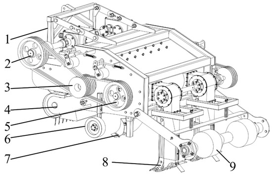
Figure 1.
Structural diagram of the direct-injection straw deep-burying machine. 1. Frame; 2. Transmission system; 3. Crushing device; 4. Picking device; 5. Mechanical–pneumatic-conveying device; 6. Depth-limiting device; 7. Ridging device; 8. In situ soil-lifting device; 9. Shaping and pressing device.
2.1.2. Working Mechanism
The working principle of the in situ soil-lifting shovel for direct-injection straw deep- burial machine is shown in Figure 2. The direct-injection straw deep-burying machine is a rear three-point suspension traction system. The tractor PTO output provides the driving force for the entire machine through the gearbox, and the pulley drive drives the crushing and conveying devices, while the sprocket drive drives the picking device. When the machine moves forward, the ridging device performs the ridging operation, and the in situ soil-lifting device completes the in situ soil-lifting operation in the ridge. The picking device picks up the straw and then transports it to the crushing machine. The crushed straw thrown back is sent to the mechanical-conveying device under the airflow action and transported to the pneumatic-conveying device under the movement of the spiral auger and straw-conveying blades. The straw is transported to the space behind the in situ soil-lifting device under the direction of the high-speed fan throwing blades, and the soil falls back to complete the deep burial operation of the straw. The shaping and pressing device compresses and reshapes the ridge shape forming a clean seed bed.
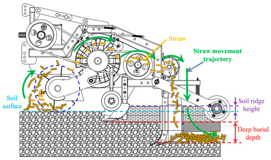
Figure 2.
Operating principle of the direct-injection straw deep-burying machine.
During the operation, the tip of the in situ soil-lifting shovel breaks the soil, and the lifting plate lifts the soil without flipping. After the in situ soil-lifting shovel, a particular space is formed, and the mechanical–pneumatic-conveying device guides the straw into this space through the straw-conveying duct. The in situ soil-lifting shovel lifts the soil and naturally falls back, completing the deep burying of straw, reducing the amount of soil movement, and ensuring the structure of the plow layer.
2.2. Design of Key Components
2.2.1. Structural Design of In Situ Soil-Lifting Shovel
When designing the structure of the in situ soil-lifting shovel, it is necessary to consider both the penetration capacity of the shovel tip and the soil-lifting plate and to reduce the operational resistance.
The in situ soil-lifting device is shown in Figure 3, mainly composed of a fixed plate, U-shaped bolts, and an in situ soil-lifting shovel. The in situ soil-lifting shovel mainly includes a shovel handle, shovel tip, and soil-lifting plate.
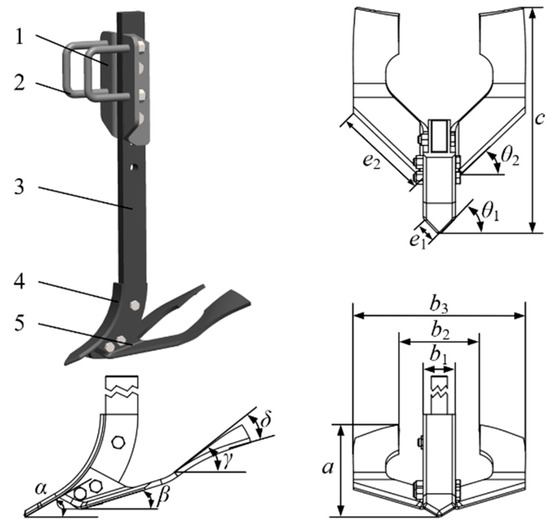
Figure 3.
Structural diagram of the in situ soil-lifting device. 1. Fixed plate; 2. U-shaped bolts; 3. Shovel handle; 4. Shovel tip; 5. Soil-lifting plate; α. The angle of penetration; β. Soil-opening angle; γ. Soil-lifting angle; δ. Camber angle.
The angle between the tip of the in situ soil-lifting shovel and the horizontal plane is the angle of penetration α; the size ranges from 20° to 30°. The angle between the front section of the in situ soil-lifting shovel and the horizontal plane is the soil-opening angle β, which ranges from 10° to 20°. The angle between the rear end of the in situ soil scraper and the horizontal plane is the angle of soil-lifting angle γ; the size ranges from 30° to 50°. The outward bending angle of the rear end plane of the original lifting shovel is camber angle δ, and the size ranges from 20° to 40°.
According to the camber angle δ, three types of soil-lifting plates were designed: outward inclined, non-inclined, and inward inclined, as shown in Figure 4. Three different in situ soil-lifting shovels were designed based on the different soil-lifting plates.
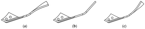
Figure 4.
Three different inclination angles of soil-lifting plates. (a) Outward inclined; (b) Non-inclined; (c) Inward inclined.
2.2.2. Force Analysis of In Situ Soil-Lifting Shovel
The force analysis of the in situ soil-lifting shovel is mainly subjected to the force of the shovel tip and the soil-lifting plate during soil lifting and straw deep-burying operations. The following is an analysis of the force exerted by the inclination of the in situ soil-lifting shovel when the soil plate is tilted outward.
- Analysis of the force on the tip of the in situ soil-lifting shovel
During the operation process of the in situ soil-lifting shovel, the shovel tip is mainly subjected to the horizontal traction force of the in situ soil-lifting shovel, the pressure of the soil at the bottom of the ditch on the shovel tip, and its gravity [19,20,21]. The stress situation is shown in Figure 5.
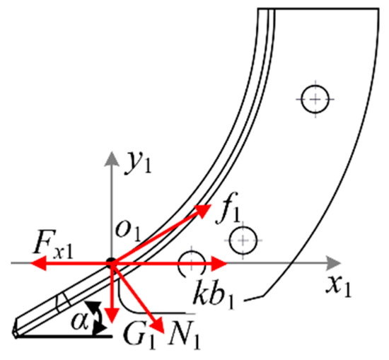
Figure 5.
Analysis diagram of the force on the tip of the in situ soil-lifting shovel.
Through force analysis, the force balance equation in the horizontal direction of the shovel tip of the in situ soil-lifting shovel is:
where Fx1 is the horizontal traction force exerted on the tip of the in situ soil-lifting shovel (N); N1 is the positive pressure applied to the normal direction of the shovel tip of the in situ soil-lifting shovel (N); F1 is the frictional force acting on the tip of the in situ soil-lifting shovel (N); b1 is the width of the shovel tip of the in situ soil-lifting shovel (mm); α is the angle at which the tip of the in situ soil-lifting shovel enters the soil (°); k is the pure cutting resistance of soil per unit width (N/mm);
The force balance equation for the tip of the in situ soil-lifting shovel in the vertical direction is:
where μ1 is the friction coefficient between the soil and the tip of the in situ soil-lifting shovel; G1 is the self-gravity of the tip of the in situ soil-lifting shovel (N).
The pure cutting resistance of soil is relatively small and can be ignored. Substituting Formulas (2) and (3) into Formula (1) yields:
From Equation (4), it can be seen that the angle of penetration α there significantly impacts the resistance of the in situ soil-lifting shovel, mainly affecting its penetration performance and forward resistance. As the angle of penetration α increases, the penetration ability deteriorates, and the resistance increases. The angle of penetration α decreases, and the effect of loose soil lifting is poor. Based on the physical characteristics of the soil when returning straw to the field, and in combination with the design of the deep loosening shovel angle in the agricultural machinery design manual, determines the in situ soil-lifting shovel tip angle into the soil α 25° [22].
- 2.
- Analysis of the force on the lifting plate of the in situ soil-lifting shovel
The lifting plate of the in situ soil-lifting shovel is an essential factor affecting the deep burial effect of straw and the operation resistance. To explore the optimal parameters of the lifting plate structure of the in situ soil-lifting shovel, a mechanical contact model between the lifting plate and the soil is established, and the stress analysis of the lifting plate is carried out. As shown in Figure 6, the process of the soil-lifting shovel’s lifting plate is mainly divided into three stages, namely the (I) stage of oblique cutting of soil in the front section of the soil plate and lifting of soil; in the (II) stage, the middle section of the soil-lifting plate further lifts the soil and separates the soil; in the (III) stage, the soil is lifted and separated from the soil after the soil plate is lifted, completing the natural fall of the soil.
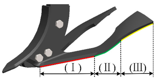
Figure 6.
Schematic diagram of the three operation stages of the in situ soil-lifting shovel’s lifting plate.
Establish a Cartesian coordinate system o2x2y2 at any point on the surface of the front and middle sections of the lifting plate, with the x2 axis indicating the forward direction of the lifting plate during operation and the y2 axis indicating the vertical direction. Analyze the stress situation of the lifting plate when it comes into contact with soil particles in the (I) stage, including the soil support force N2, soil friction force f2, and its gravity G2. The combined force acting on the lifting plate is the forward resistance Fx2 of the lifting plate [23]. As shown in Figure 7, the force balance equation for the (I) stage is:
where Fx2 is the horizontal traction force applied to the lifting plate in the (I) stage (N); N2 is the positive pressure applied to the normal direction of the lifting plate (N); f2 is the frictional force acting on the lifting plate (N); β is the lifting angle of the soil plate (°); μ2 is the friction coefficient between the soil and the lifting plate; G2 is the gravity of the lifting plate itself (N).

Figure 7.
Stress analysis diagram of the lifting plate in the (I) stage.
Substituting Equations (6) and (7) into Equation (5) yields:
The force acting on the soil plate in the (II) stage is similar to that in the (I) stage. Similarly, it can be concluded that the force equation in the (II) stage is:
where Fx3 is the horizontal traction force applied to the lifting plate in the (II) stage (N); γ is the soil-lifting angle of the soil plate (°).
From Equations (8) and (9), it can be seen that the forward resistance Fx2 and Fx3 of the soil-lifting plate in stages (I) and (II) are related to the soil-opening angle β, soil-lifting angle γ. When increasing, the traction force increases regarding soil-opening angle β and soil-lifting angle γ. After too little, the effect of raising the soil cannot be achieved. Based on the relevant knowledge of the Agricultural Machinery Design Manual, determine the soil-opening angle β where the range of values is 10° to 20°, determining the soil-lifting angle γ where the value range is 30° to 50°. The following text will explore its optimal parameter combination through EDEM simulation experiments.
The force on the lifting plate of the in situ soil-lifting shovel in the (III) stage is shown in Figure 8. At any point on the surface of the lifting plate in the (III) stage, a spatial Cartesian coordinate system o4x4y4z4 is established, with the direction perpendicular to the forward direction as the x4 axis, the direction tangential to the (II) stage working surface as the y4 axis, and the direction perpendicular to the (II) stage working surface as the z4 axis. Analyze the stress situation of the soil-lifting plate when it comes into contact with soil particles in the third stage, including the positive pressure N4 on the lifting plate, which is perpendicular to the inclined plane. The horizontal traction force F4 in the forward direction is along the direction of the implement’s forward movement. The direction of friction force f4 at o4 is the flow direction of soil particles at o4. The self-gravity G2 is perpendicular to the forward direction and downward. According to the analysis, the equilibrium equations for the x4, y4, and z4 axes are:
where F4 is the horizontal traction force on the soil-lifting plate in the (III) stage (N); N4 is the positive pressure applied to the normal direction of the lifting plate (N); f4 is the frictional force acting on the lifting plate (N); δ is the camber angle of the soil-lifting plate (°); θ1 is the angle between the projection of frictional force f4 in the o4x4y4 plane and the y4 axis (°); θ2 is the angle between the projection of positive pressure N4 in the o4x4y4 plane and the y4 axis (°).
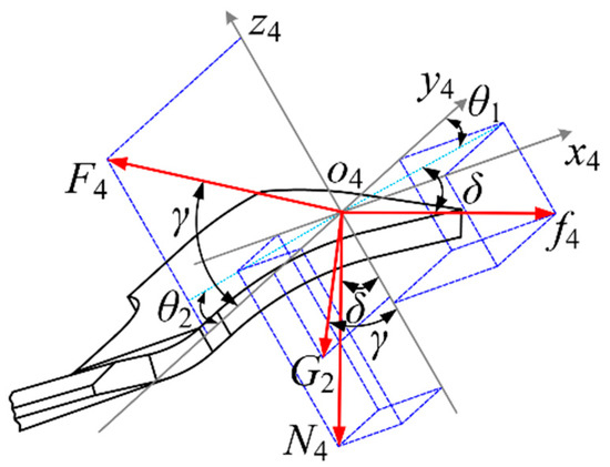
Figure 8.
Stress analysis diagram of the lifting plate in the (III) stage.
Angle θ1 is related to the direction of soil flow at point o4. The direction of positive pressure N4 is fixed, so θ2 the angle is fixed and constant. By combining Formulas (10)–(13), it can be concluded that the forward direction traction force F4 is:
According to Formulas (14) and (15), it can be seen that the horizontal traction force in the forward direction is related to the soil-lifting angle of the in situ soil-lifting shovel’s lifting plate γ, regarding camber angle δ.
To determine the camber angle δ value range for different camber angle angles δ, three types of in situ soil-lifting shovels were designed for single-factor simulation pre-testing, as shown in Figure 9.
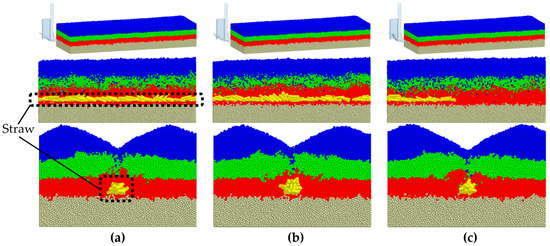
Figure 9.
Simulation analysis diagram of three types of in situ soil-lifting shovels under shovel-type conditions. (a) Outward inclined; (b) Non-inclined; (c) Inward inclined.
Figure 9 shows that under the three types of in situ soil-lifting shovels, the soil plow layer did not change. Regarding the depth of straw burial, the outward and normal conditions were better than the inward inclination conditions. Statistical analysis of the amount of deeply buried straw and operational resistance data under different shovel types are shown in Figure 10 and Figure 11.
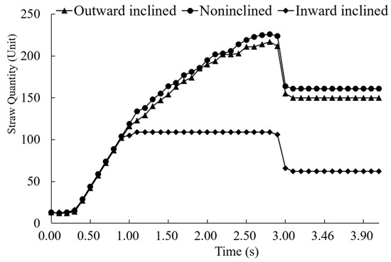
Figure 10.
Diagram of the quantity of deeply buried straw with in situ soil-lifting shovels under different shovel types.
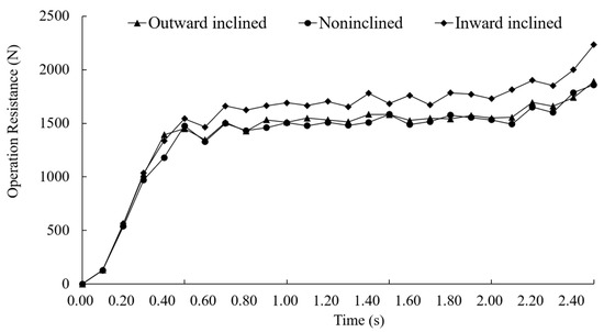
Figure 11.
Diagram of the variation in operational resistance of in situ soil-lifting shovels under different shovel types.
The analysis shows that the depth of straw burial under outward inclination and the non-inclined shovel type is stable over time. After 1.1 s, the straw cannot be deeply buried under the inward inclined shovel type. Under the three shovel conditions, the pressure exerted by the in situ soil-lifting shovel is not significantly different. In contrast, the operating resistance is more significant under inward-inclined conditions than that under outward-inclined and non-inclined conditions. Analysis shows that under inward-inclined conditions, the soil aggregation effect is better, which hinders the transportation of straw and affects the downward transport of straw in the straw-conveying duct. The inward incline of the soil plate is compressed by the soil, resulting in more excellent resistance. Based on the above analysis, under the condition of inward inclination, the effect of straw deep burial is not good. Under non-inclined conditions, the effect of straw burial is not much different from that of outward inclination, so the camber angle δ is set and the range is 0° to 40°.
2.3. EDEM Simulation
2.3.1. Purpose and Method of Simulation Test
To determine the optimal combination parameters of each angle of the soil-lifting plate of the in situ soil-lifting shovel and to obtain trenches that meet the requirements of deep straw burial and small operating resistance, combined with the above analysis, the simulation regression orthogonal test was conducted, with the soil-opening angle, soil-lifting angle, and camber angle as the main factors affecting the straw deep-burial effect, and the amount of deeply buried straw and operating resistance as the evaluation indicators to determine the optimal parameter combination [24,25,26].
2.3.2. Construction of a Soil Model and a Geometric Simulation Model for an In Situ Soil-Lifting Shovel
- Model parameters of in situ soil-lifting shovel
To simplify the computational complexity of the computer, the in situ soil-lifting shovel is simplified by hiding and removing other components except for the shovel handle, shovel tip, soil-lifting plate, and straw-conveying duct. Use the 3D drawing software SolidWorks to model the implementation and import it into the EDEM software in .step file format. According to the characteristics of the physical prototype trial production, the material properties of the shovel handle and straw transport conduit were set to 45 steel, and the material properties of the shovel tip and lifting plate were set to 16Mn steel. The simulation model parameters are shown in Table 1. The gravitational acceleration was set to 9.81 m/s2.

Table 1.
Simulation model parameters.
- 2.
- Soil and straw model parameters;
The physical properties of soil were closely related to the operation effect of the in situ shovel, and the soil moisture content, solidity, and soil type have an essential impact on the simulation. To ensure that the simulation results are similar to the actual work, the physical parameters of the soil in the experimental field in Xiawo Town, Shangjie District, Zhengzhou City, Henan Province were measured, and the stacking angle was calibrated in the discrete element simulation software EDEM. According to the test and combined with the simulation efficiency, the soil particle radius of 5 mm was selected as the particle model radius. The Poisson’s ratio of the soil measured in the test was 0.35, and the Shear modulus was 1.0 × 10⁶ Pa, with a soil bulk density of 2560 kg/m3. Hertz–Mindlin with bonding contact model was selected as soil particles’ indirect contact mechanics model [27]. Due to differences in soil firmness at different depths, different layer soil models were set up. In combination with the actual situation, after the straw was crushed in the field, the multi-ball model was selected, and the extended linear model with a diameter of 16 mm and a length of 80 mm was set as the straw particle model. The Hertz–Mindlin non-sliding contact model was selected as the straw model, and the straw density was 240 kg/m3, the Poisson’s ratio’s ratio was 0.4, and Shear modulus was 1 0 × 106 Pa. According to previous publications [28,29,30,31], the dynamic friction coefficient, static friction coefficient, and recovery factor between 45 steel–soil particles, 16Mn steel–soil particles, soil particles–soil particles, and 45 steel–straw particles were set up. The relevant parameters are shown in Table 2.
Table 2.
Material contact parameters of the simulation.
Set up four layers of polygon virtual planes in EDEM to generate soil particles. The filled soil model has a length L of 2200 mm and a width B of 700 mm. The first layer has a height h1 of 110 mm, the second layer has a height h2 of 100 mm, the third layer has a height h3 of 100 mm, and the fourth layer has a height h4 of 100 mm. The simulation model is shown in Figure 12.
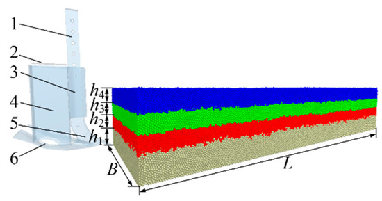
Figure 12.
Virtual soil bin model. 1. Shovel handle; 2. Straw generation plane; 3. Drag reduction fixing plate; 4. Straw transport conduit; 5. Shovel tip; 6. Soil-lifting plate.
2.4. Orthogonal Test
2.4.1. Experimental Design
According to the theoretical analysis and single-factor pre-test verification results, the soil-opening angle, soil-lifting angle, and camber angle were selected as the test factors to optimize the parameters better and determine the interaction between the test factors. The amount of deeply buried straw and operating resistance were used as the three-factor three-level quadratic regression orthogonal test indicators. The test factors and coding are shown in Table 3.
Table 3.
Test factors and coding.
2.4.2. Measurement of the Quantity of Deeply Buried Straw
Extract changes in the amount of straw in the soil tank before and after the stable operation period. Use the analysis option in the EDEM software to export the quantity of deeply buried straw, as shown in Figure 13.
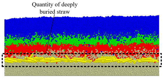
Figure 13.
Schematic diagram for measuring the quantity of deeply buried straw.
2.4.3. Measurement of Operation Resistance
By using EDEM software, extract the resistance of the in situ soil-lifting shovel operation during the stable operation period during the simulation process. At the same time, export the operation resistance at each time node in the software analyst option, and calculate the average value of the operation resistance throughout the entire process, as shown in Figure 14.
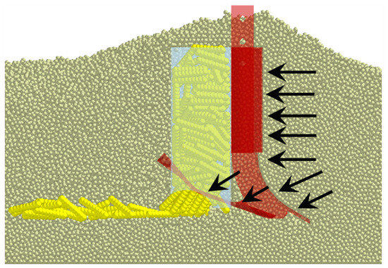
Figure 14.
Schematic diagram for measuring operation resistance.
2.5. Field Experiment
To further verify the operation effect of the designed in situ soil-lifting shovel, field tests of the whole machine were conducted in the experimental field of Xiawo Town, Shangjie District, Zhengzhou City, Henan Province. The average annual temperature there was 14.5 °C and the annual precipitation was 638 mm. The average soil moisture content of the experimental field was 14.63%, the soil density was 2560 kg/m3, the average soil compaction at a depth of 10 cm was 365 kPa, and at 30 mm was 496 kPa. The diameter range of the maize straw was 11.31~19.47 mm and the average water content was 16.9% ± 5%. The coverage of maize straw was 1 kg/m2 and the on-site test is shown in Figure 15.
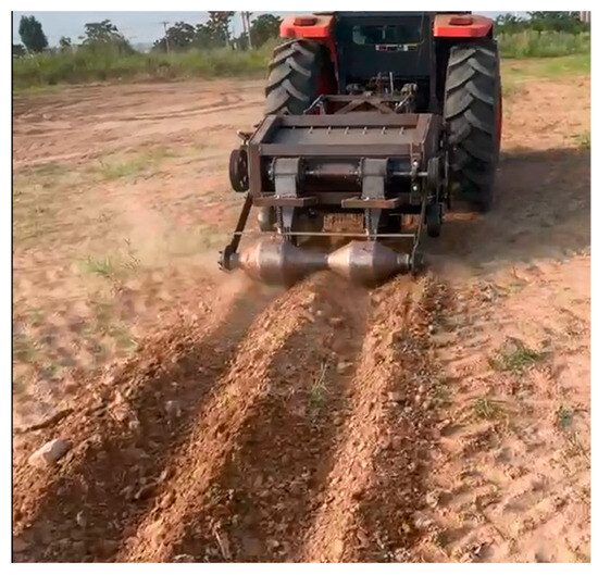
Figure 15.
Field experiment.
3. Results and Discussion
3.1. Simulation Operation Process
During the simulation process of the in situ soil-lifting shovel, the in situ soil-lifting shovel model was set to be located at one end of the soil groove for initial operation, as shown in Figure 16. Referring to the forward speed of the straw-returning machine during the process, the initial set of the machine’s forward speed vm is 0.83 m/s, and the depth of the in situ soil-lifting shovel entering the soil is 30 mm. To ensure simulation stability, set its fixed time step to 5.10 × 10⁻⁵ s (i.e., 10% of the Rayleigh time step), with a total simulation time of 3.4 s and an adequate operation time of 3.0 s, of which 3.0–3.4 s were when the machine leaves the soil tank and waits for the particles to stabilize.
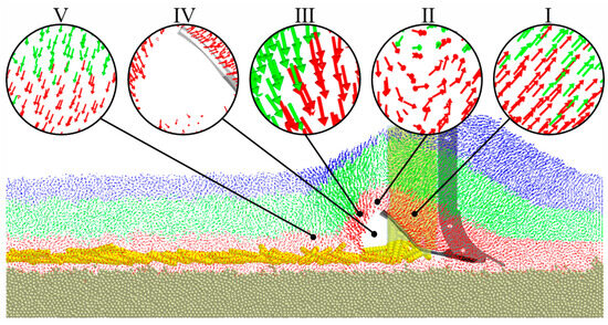
Figure 16.
Simulated operation process of in situ soil-lifting shovel.
The simulation analysis shows that during the in situ soil-lifting shovel operation, the movement undergoes four processes: I: soil being lifted → II: soil twisting → III: for-ward falling → V: backward falling. Through the soil particle movement of processes I, II, and III, a particular space is formed at IV. The straw conveyed downwards by the straw transport pipe fills the space behind the in situ soil-lifting shovel, completing the straw burial.
3.2. Analysis of Simulation Results
The simulation test results of the in situ soil-lifting shovel are shown in Table 4, and data processing and statistical analysis were conducted using Design Expert software. A, B, and C are the factor coding values in the table.
Table 4.
Experimental design and results.
3.2.1. Regression Analysis and Significance Testing
Perform secondary regression analysis on the experimental results and perform multiple regression fitting to obtain the regression equation between the experimental indicator of deep buried straw quantity Y1 and the operational resistance Y2, as shown in Formula (16), and test its significance.
Table 5 shows the results of analysis of variance. The quadratic regression model for the quantity of deeply buried straw (Y1) had a p < 0.01, indicating that the regression model was extremely significant; C and B2 had a significant impact; A2 and C2 had a significant impact. The misfit term p > 0.1, and the misfit was not significant, indicating that the quadratic regression equation fitted by the model was consistent with the reality, and can correctly reflect the relationship between the quantity of deeply buried straw (Y1) and the soil-opening angle A, soil-lifting angle B, and camber angle C. The regression model can better predict different test results in the optimization test. The analysis of variance showed that the significance of each factor on the quantity of deeply buried straw (Y1) was in the order of camber angle C, soil-opening angle A, and soil-lifting angle B.
Table 5.
Variance analysis of experimental results.
The quadratic regression model of operation resistance (Y2) (p < 0.05) indicates that the regression model was significant. The impact of B was extremely significant; A had a significant effect. With the misfit term p > 0.1, the misfit was not significant, which indicates that the quadratic regression equation fitted by the model was consistent with the reality. The variance analysis showed that the significance of each factor on the operation resistance (Y2) is in the order of significance to small: soil-lifting angle B, soil-opening angle A, and camber angle C.
where A, B, and C are the factor coding values.
3.2.2. Response Surface Analysis
Within the range of experimental parameters, there were differences in the significant order of the experimental factors that affected the two major performance evaluation indicators of straw deep burial and operational resistance. To more clearly and intuitively describe the impact of each experimental factor and its interaction on the experimental evaluation indicators, a response surface diagram of the interaction effect of each factor was drawn based on the regression model analysis results. The impact of experimental factors on straw deep burial is shown in Figure 17; the influence of experimental factors on job resistance is shown in Figure 18.
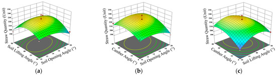
Figure 17.
Response surface of experimental factors to straw quantity. (a) C = 20°; (b) B = 40°; (c) A = 15°.
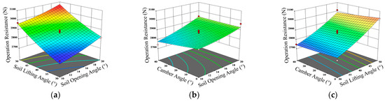
Figure 18.
Response surface of experimental factors to operation resistance. (a) C = 20°; (b) B = 40°; (c) A = 15°.
When the camber angle was at the central level (20°), and the soil-opening angle was fixed, the quantity of deeply buried straw increases first and then decreases with the rise of the soil-lifting angle. When the soil-lifting angle was constant, the amount of deeply buried straw first increases and then decreases with the increase of the soil-opening angle. When the soil-lifting angle changes, the variation range of the quantity of deeply buried straw was relatively large, and the soil-lifting angle has a more significant impact on the amount of deeply buried straw index (Figure 17a). When the soil-lifting angle was at the central level (40°) and the soil-opening angle was constant, the quantity of deeply buried straw increases first and then decreases with the rise of the camber angle. When the camber angle was constant, the amount of deeply buried straw increases first and then decreases with the rise of the soil-opening angle. When the camber angle changes, the change range of the quantity of deeply buried straw is extensive and the camber angle has a more significant impact on the amount of deeply buried straw indicators (Figure 17b). When the soil-opening angle was at the central level (15°) and the soil-lifting angle was constant, the quantity of deeply buried straw increases first and then decreases with the rise of the camber angle. When the camber angle was constant, the amount of deeply buried straw increases first and then decreases with the rise of the soil-lifting angle. When the camber angle changes, the change range of quantity of deeply buried straw was extensive, and the camber angle had a more significant impact on the amount of deeply buried straw indicators (Figure 17c).
When the camber angle was at the center level (20°) and the opening angle was fixed, the operating resistance increases with the increase of the soil-lifting angle. When the soil-lifting angle was constant, the working resistance increases with the rise of the soil-opening angle. When the soil-lifting angle changes, the range of variation in operational resistance was relatively large and the soil-lifting angle had a more significant impact on operational resistance indicators (Figure 18a). When the soil-lifting angle was at the center level (40°) and the soil-opening angle was fixed, the operating resistance decreases with the increase of the camber angle. When the camber angle was constant, the working resistance increases with the rise of the soil-opening angle. When the soil-opening angle changes, the range of variation in working resistance is relatively large and the soil-opening angle had a more significant impact on the working resistance index (Figure 18b). When the soil-opening angle was at the central level (15°) and the soil-lifting angle was constant, the operating resistance has little change with the increase of the camber angle. When the camber angle was constant, the working resistance increases with the rise of the soil-lifting angle. When the soil-lifting angle changes, the range of variation in operational resistance was relatively large and the soil-lifting angle had a more significant impact on operational resistance indicators (Figure 18c).
The operational resistance of the in situ soil-lifting shovel increases with the increase of the soil-opening angle and soil-lifting angle, and the soil-lifting effect increases with the increase of the soil-opening angle and soil-lifting angle [32]. When the soil-opening angle was 10° and the soil-lifting angle was 20°, the operational resistance of the in situ soil-lifting shovel is minor, but it is not easy to form an ample space, reducing the effect of straw deep burial. When the opening angle was 20° and the soil-lifting angle was 50°, the lifting effect of the in situ soil-lifting shovel is more substantial. Although it enhances the lifting effect of the in situ soil-lifting shovel on the soil, it is easy to cause the soil to accumulate in front of the shovel tip, forming a soil compaction area. The camber angle mainly affects the soil’s falling effect. Suitable soil-opening, soil-lifting, and camber angles can reduce soil accumulation and compression, reduce operational resistance, and achieve better straw burial.
3.2.3. Optimization and Verification
The regression model for the quantity of deeply buried straw burial and operational resistance was optimized and solved to obtain the optimal combination of structural parameters for various angles of the in situ soil-lifting shovel. Using the optimization module, the optimization objective was to maximize the quantity of deeply buried straw and minimize operational resistance. The objective function was established as follows:
The optimal solution can be obtained according to formula (17), and the optimal operation parameters were as follows: the soil-opening angle was 16.84°, the soil-lifting angle was 36.74°, the camber angle was 29.60°, the quantity of deeply buried straw was 228.29, and the operation resistance was 2840.45 N. Considering the operability of manufacturing, the optimized adjustment were as follows: the soil-opening angle was 17°, the soil-lifting angle was 37°, and the camber angle was 30°. The optimal structure of the in situ soil-lifting shovel optimized by simulation experiments provides a basis for subsequent field experiments.
Based on the principles of low soil disturbance and low operational resistance, as well as agronomic design requirements, the height a of the in situ soil-lifting shovel was designed to be 140 mm, the length c was 350 mm, b1 was 50 mm, b2 was 130 mm, b3 was 260 mm, e1 was 30 mm, and e2 was 150 mm.
3.3. Field Experiment Analysis
According to the theoretical analysis and simulation results, when the soil-opening angle is 17°, the soil-lifting angle is 37°, and the camber angle is 30°. The field experiment was conducted. The effect of straw deep burial is shown in Figure 19 and the field test results are shown in Table 6.
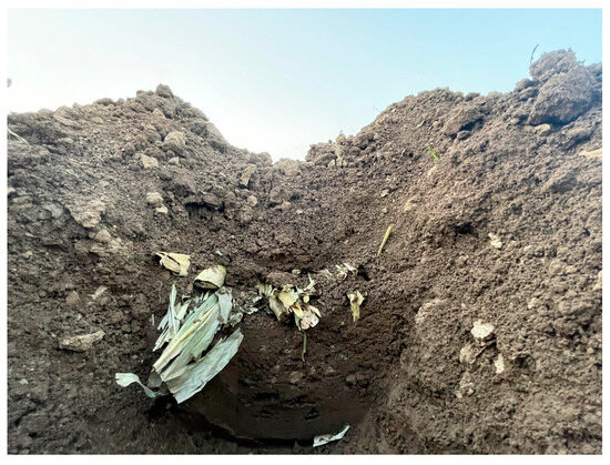
Figure 19.
Effect diagram of straw deep burial.
Table 6.
Field test results of operational resistance.
Figure 19 and Table 6 showed that the quantity of deeply buried straw was 90.21%, and the average operating resistance value was 3145.95 N. In the study by Tian Yang et al., the deep burial rate of straw was 94%, slightly higher than the study in this article. However, there were problems such as poor compaction of straw covering the soil [33]. The error between the operational resistance value and the simulation experiment was only 11%. Our analysis suggests that during field experiments, soil characteristics such as different moisture content and external factors such as wind power and machine vibration significantly impact the actual operation results, leading to deviations in simulation test values. At the same time, the maximum and average depth of straw burial were measured. The maximum depth was 33.58 cm, and the average was 29.73 cm.
4. Conclusions
- (1)
- A direct-injection method for the deep burial of straw was proposed, and an in situ soil-lifting shovel was designed based on the principle of oblique cutting. While obliquely cutting the soil, the soil was lifted in situ to form a deep burial space for straw and complete the deep burial of straw.
- (2)
- Theoretical analysis was conducted on the force acting on the tip of the in situ soil-lifting shovel, and the angle of penetration of the shovel tip into the soil was determined. Based on the analysis of the three stages of the operation of the soil-lifting plate part, three soil-lifting plates were designed according to the different camber angles, and then three in situ soil-lifting shovel structures were designed. The value range of the camber angle was determined by analyzing three kinds of in situ soil-lifting shovels.
- (3)
- The DEM method was used to analyze the operational resistance and the amount of deeply buried straw. The results showed that as the soil-opening angle increased, the amount of deeply buried straw first increased and then decreased, increasing operational resistance. As the soil-lifting angle increased, the amount of deeply buried straw first increased and then reduced, leading to an increase in operational resistance. With the rise of camber angle, the amount of deeply buried straw first increases and then decreases, and the operational resistance decreases. Aiming at the maximum amount of deeply buried straw and the minimum operational resistance, the soil-opening angle of the in situ soil-lifting shovel was 17°, the soil-lifting angle was 37°, and the camber angle was 30°.
- (4)
- The field test results showed that when the angle of penetration was 25°, the soil-opening angle was 17°, and the soil-lifting angle was 37°. The camber angle was 30°, the amount of deeply buried straw was 90.21%, the operating resistance was 3145.95 N, and the error with the simulation experiment was only 11%.
The designed direct-injection straw deep-burying machine has the potential to make an essential contribution to improving the straw deep burial quality of maize straw in China. However, further research is needed on several aspects, including long-term experiments, energy consumption research, and device vibration research. Furthermore, in the future, the operating parameters of straw deep-burying machines should be researched to improve the deep burial rate of maize straw.
Author Contributions
Conceptualization, Z.T.; writing—original draft preparation, Z.T. and H.L.; writing—review and editing, J.H., Q.W., C.L., C.W., G.Z., D.C. and D.L. All authors have read and agreed to the published version of the manuscript.
Funding
This research was funded by the China Agriculture Research System of MOF and MARA (Grant No. CARS-03) and the 2115 Talent Development Program of China Agricultural University and Chinese Universities Scientific Fund (Grant No. 2021TC105).
Institutional Review Board Statement
Not applicable.
Data Availability Statement
Not applicable.
Acknowledgments
We would like to express our gratitude to all the members of the Conservation Tillage Research Centre. Additionally, we sincerely appreciate the work of the editor and the reviewers of this paper.
Conflicts of Interest
The authors declare no conflict of interest.
References
- He, J.; Li, H.; Chen, H.; Lu, C.; Wang, Q. Research progress of conservation tillage technology and machine. Trans. Chin. Soc. Agric. Mach. 2018, 49, 1–19. [Google Scholar]
- Nyakudya, I.W.; Stroosnijder, L. Conservation tillage of rainfed maize in semi-arid Zimbabwe: A review. Soil Tillage Res. 2015, 145, 184–197. [Google Scholar] [CrossRef]
- Shao, J.; Gao, C.; Afi Seglah, P.; Xie, J.; Zhao, L.; Bi, Y.; Wang, Y. Analysis of the Available Straw Nutrient Resources and Substitution of Chemical Fertilizers with Straw Returned Directly to the Field in China. Agriculture 2023, 13, 1187. [Google Scholar] [CrossRef]
- Berhane, M.; Xu, M.; Liang, Z.; Shi, J.; Wei, G.; Tian, X. Effects of long-term straw return on soil organic carbon storage and sequestration rate in North China upland crops: A meta-analysis. Glob. Chang. Biol. 2020, 26, 2686–2701. [Google Scholar] [CrossRef]
- Hiloidhari, M.; Das, D.; Baruah, D.C. Bioenergy potential from crop residue biomass in India. Renew. Sustain. Energy Rev. 2014, 32, 504–512. [Google Scholar] [CrossRef]
- Liu, J.; Li, J.; Zhou, Y.; Fu, Q.; Zhang, L.; Liu, L. Effects of straw mulching and tillage on soil water characteristics. Trans. Chin. Soc. Agric. Mach. 2019, 50, 333–339. [Google Scholar]
- Shi, Z.; Wang, F.; Wang, J.; Li, X.; Sun, R.; Song, C. Utilization Characteristics, Technical Model and Development Suggestion on Crop Straw in China. J. Agric. Sci. Technol. 2019, 21, 8–16. [Google Scholar]
- Wang, Y.; Yang, S.; Sun, J.; Liu, Z.; He, X.; Qiao, J. Effects of Tillage and Sowing Methods on Soil Physical Properties and Corn Plant Characters. Agriculture 2023, 13, 600. [Google Scholar] [CrossRef]
- Song, J.; Zeng, X.; Wang, Y.; Bai, L. A review on crop straw returning to field:Effects, problems and countermeasures. Chin. J. Ecol. 2020, 39, 1715–1722. [Google Scholar]
- Zhuang, Q.; Huang, Y.; Jiang, X.; Zi, Y.; Lei, Y. Straw Returning and Its Effective Returning Method: Research Progress. Chin. Agric. Sci. Bull. 2019, 35, 38–41. [Google Scholar]
- Wang, J.; Zhang, X.; Tang, H.; Wang, J.; Weng, W.; Yang, D. Optimal Design and Experiment of Deep-buried Reverse Rotating Sliding Cutting Straw Returning Blade. Trans. Chin. Soc. Agric. Mach. 2021, 52, 28–39. [Google Scholar]
- Lin, J.; Qi, L.; Li, B.; Bo, H.; Wu, N.; Gao, W.; Zhang, T.; Meng, F. Design and Experimental Study of Maize Straw Ridge-furrow-strip Mixed Burying Machine. J. Shenyang Agric. Univ. 2018, 49, 697–708. [Google Scholar]
- Tian, Y.; Lin, J.; Li, B. Design and Test of Conveying Device of Pneumatic Straw Deep Burying and Returning Machine. Trans. Chin. Soc. Agric. Mach. 2018, 49, 36–44. [Google Scholar]
- Chen, G.; Lu, C.; He, J.; Wang, C.; Wang, X.; Wang, Q. Design and Experiment of Straw Pickup-Crushed and Deep Buried Device under Strip-tillage. Trans. Chin. Soc. Agric. Mach. 2021, 52, 16–27. [Google Scholar]
- Song, J.; Lin, J.; Ma, T.; Lv, Q.; Tian, Y. Design and Test of Rotating Spade Type Maize Straw Returning Root Deep Machine. J. Agric. Mach. 2018, 40, 95–99. [Google Scholar]
- Aikins, K.A.; Ucgul, M.; Barr, J.B.; Awuah, E.; Antille, D.L.; Jensen, T.A.; Desbiolles, J.M.A. Review of Discrete Element Method Simulations of Soil Tillage and Furrow Opening. Agriculture 2023, 13, 541. [Google Scholar] [CrossRef]
- Yuan, Y.; Wang, J.; Zhang, X.; Zhao, S. Effect of Rotary Speed on Soil and Straw Throwing Process by Stubble-Crushing Blade for Strip Tillage Using DEM-CFD. Agriculture 2023, 13, 877. [Google Scholar] [CrossRef]
- Zhang, J.; Xia, M.; Chen, W.; Yuan, D.; Wu, C.; Zhu, J. Simulation Analysis and Experiments for Blade-Soil-Straw Interaction under Deep Ploughing Based on the Discrete Element Method. Agriculture 2023, 13, 136. [Google Scholar] [CrossRef]
- Zhang, X.; Zhang, R.; Ru, S.; Zhang, X.; Li, Y.; Liang, D. Design and experiment of pre-soil-breaking chisel-type subsoilers for banana field in hot areas of Hainan Province, China. Trans. Chin. Soc. Agric. Eng. 2020, 36, 49–55. [Google Scholar]
- Li, Y.; Cao, Z.; Zhan, X.; Yang, Q.; Cui, J.; Li, Y. Optimal Design and Test of Orchard Chisel-Type Shovel Subsoiler. Trans. Chin. Soc. Agric. Mach. 2021, 52, 19–25. [Google Scholar]
- Liu, R.; Li, Y.; Liu, C.; Liu, L. Design and Experiment of Shovel Type Wide Seedling Belt Oat Seeding Furrow Opener. Trans. Chin. Soc. Agric. Mach. 2021, 52, 89–96. [Google Scholar]
- Hang, C.; Zhang, P.; Li, W.; Huang, Y.; Zhu, R. Experiment research on influence of rake angle on soil hardness variation under sub-soiling. J. Chin. Agric. Mech. 2016, 37, 36–40. [Google Scholar]
- Wang, J.; Li, X.; Gao, P.; Na, M.; Wang, Q.; Hou, W. Design and Experiment of High Efficiency Drag Reducing Shovel for Carrot Combine Harvester. Trans. Chin. Soc. Agric. Mach. 2020, 51, 93–103. [Google Scholar]
- Zeng, Z.W.; Ma, X.; Cao, X.L.; Li, Z.H.; Wang, X.C. Critical Review of Applications of Discrete Element Method in Agricultural Engineering. Trans. Chin. Soc. Agric. Mach. 2021, 52, 1–20. [Google Scholar]
- Fang, H.M.; Ji, C.Y.; Farman, A.C.; Guo, J.; Zhang, Q.Y.; Chaudhry, A. Analysis of Soil Dynamic Behavior during Rotary Tillage Based on Distinct Element Method. Trans. Chin. Soc. Agric. Mach. 2016, 47, 22–28. [Google Scholar]
- Mustafa, U.; John, M.F.; Chris, S. 3D DEM tillage simulation: Validation of a hysteretic spring (plastic) contact model for a sweep tool operating in a cohesionless soil. Soil Tillage Res. 2014, 144, 220–227. [Google Scholar]
- Tekeste, M.Z.; Balvanz, L.R.; Hatfield, J.L.; Ghorbani, S. Discrete element modeling of cultivator sweep-to-soil interaction: Worn and hardened edges effects on soil-tool forces and soil flow. J. Terramechanics 2019, 82, 1–11. [Google Scholar] [CrossRef]
- Wang, J.; Tang, H.; Wang, J.; Huang, H.; Lin, N.; Zhao, Y. Numerical Analysis and Performance Optimization Experiment on Hanging Unilateral Ridger for Paddy Field. Trans. Chin. Soc. Agric. Mach. 2017, 48, 72–80. [Google Scholar]
- Ma, Y.; Wang, A.; Zhao, J.; Hao, J.; Li, J.; Ma, L.; Zhao, W.; Wu, Y. Simulation analysis and experiment of drag reduction effect of convex blade subsoiler based on discrete element method. Trans. Chin. Soc. Agric. Eng. 2019, 35, 16–23. [Google Scholar]
- Ma, S.; Xu, L.; Xing, J.; Yuan, Q.; Yu, C.; Duan, Z.; Chen, C.; Zeng, J. Development of unilateral cleaning machine for grapevine buried by soil with rotary impeller. Trans. Chin. Soc. Agric. Eng. 2018, 34, 1–10. [Google Scholar]
- Yu, C.; Wang, Q.; Li, H.; He, J.; Lu, C.; Liu, H. Design and Experiment of Spiral-Split Sowing Strip Cleaning Device. Trans. Chin. Soc. Agric. Mach. 2020, 51, 212–219. [Google Scholar]
- Yang, Y.; Zhang, H.; Feng, T.; Lin, Q.; Xue, M.; Li, Z.; He, W.; Mi, X. Topsoil and subsoil combined cultivator and top-soiling experiment. J. Mech. Eng. 2012, 48, 163–168. [Google Scholar] [CrossRef]
- Tian, Y.; Lin, J.; Li, B.; Zhang, T.; Qi, L.; Wang, J. Design and test of pneumatic 1JH-2 style straw deep burying and returning machine. Trans. Chin. Soc. Agric. Eng. 2018, 34, 10–18. [Google Scholar]
Disclaimer/Publisher’s Note: The statements, opinions and data contained in all publications are solely those of the individual author(s) and contributor(s) and not of MDPI and/or the editor(s). MDPI and/or the editor(s) disclaim responsibility for any injury to people or property resulting from any ideas, methods, instructions or products referred to in the content. |
© 2023 by the authors. Licensee MDPI, Basel, Switzerland. This article is an open access article distributed under the terms and conditions of the Creative Commons Attribution (CC BY) license (https://creativecommons.org/licenses/by/4.0/).