Article

Design and Analysis of a Pneumatic Automatic Compensation System for Miss-Seeding Based on Speed Synchronization

1
College of Engineering, Huazhong Agricultural University, Wuhan 430070, China
2
Key Laboratory of Agricultural Equipment in Mid-Lower Yangtze River, Ministry of Agriculture and Rural Affairs, Wuhan 430070, China
*
Author to whom correspondence should be addressed.
Agriculture 2023, 13(6), 1232; https://doi.org/10.3390/agriculture13061232
Submission received: 22 May 2023 / Revised: 8 June 2023 / Accepted: 9 June 2023 / Published: 12 June 2023

Abstract

:
In order to solve the problems of poor seed filling performance and the low compensation accuracy of large- and medium-sized missed seeding compensation devices under medium- to high-speed conditions, a pneumatic missed seeding automatic compensation system based on speed synchronization was designed. The key structure and parameters in terms of the seed metering plate and seed feeding arm were determined by theoretical analysis. A universal compensation control system for single-seed missed seeding and continuous missed seeding was designed. With regards to exploring the working performance, some relevant bench tests were carried out, with Zhengdan-958 corn seeds and Zhonghuang-37 soybean seeds serving as the test objects. First of all, a single-factor test was conducted to determine the optimal level ranges of the factors that influence seed filling performance, such as suction hole diameter, seed stirring bar thickness, and negative pressure. The test indicators were qualified seed filling rate, multiple seed filling rate, and missed seed filling rate. Next, the Box–Behnken design test was executed to explore to the influence law of each test indicator on corn seed filling performance. Then, the parameter optimization module was applied to achieve the best combination of operating parameters for the test factors. The optimal combination of parameters was a suction hole diameter of 5.3 mm, seed stirring bar thickness of 2.9 mm, and negative pressure of 4.1 kPa. Based on the optimal combination, a verification test of corn seed filling performance was performed, and the corresponding evaluation indexes were a qualified seed filling rate of 95.46%, multiple seed filling rate of 2.47%, and missed seed filling rate of 2.07%. Lastly, a seed feeding performance verification test was employed with the seeding speed as the impact factor to verify the compensation accuracy of single-seed missed seeding and continuous missed seeding compensation. The results of the verification test indicate that, for corn seeds, when the seeding speed falls within the range of 8 to 12 km/h, the effective single-seed feeding rate exceeds 88%, the average single-seed feeding time is less than 0.18 s, the qualified seed feeding rate is higher than 90%, the multiple seed feeding rate is lower than 3%, and the missed seed feeding rate is below 7%. For soybean seeds, the effective single-seed feeding rate is higher than 85%, the average single-seed feeding time is less than 0.17 s, the qualified seed feeding rate exceeds 86%, the multiple seed feeding rate is less than 4%, and the missed seed feeding rate is below 10%. This system meets the agronomic requirements for the automatic compensation of missed seeding with respect to large- and medium-sized precision seeders, which could help to improve the operational performance of seeding machines.

1. Introduction

Seeding is a very important process of agricultural production [1]. Pneumatic precision seed metering devices have been used more and more in the process of seeding operations [2]. The device is driven by ground wheel or motor, and the seed metering plate is connected to the driving mechanism through a shaft. Therefore, it has the advantages of a compact structure, less seed damage, and high universality. However, due to the comprehensive effect of diverse seed shapes and poor fluidity, unstable negative pressure, and some uncertain vibration, it is sometimes hard to take seeds in a seed metering plate, and the chief reason for missed seeding is due to seed absence on the suction hole after passing through the seed filling area [3,4]. Missed seeding will lead to congenital yield reduction, and the simplest way to reduce this kind of loss is artificial compensation. However, artificial replanting is not only labor intensive but also inefficient [5,6]. Even if the structure of the machine has been deeply optimized, the actual miss-seeding rate is still beyond 7% [7,8]. For giant economies with large planting areas for large- and medium-sized grain crops such as corn and soybean, the amount of this kind of congenital loss in yield is amazing.
An effective way to solve this problem is to add detection and automatic compensation devices to the planter [9,10]. This is actually part of the booming field of precision agriculture, which is precisely relevant to the category of precision seeding [11,12,13,14]. Precision sowing of traditional bulk crops (such as corn, soybean, and so on) in Europe and America began after Word War II, and these crops have been able to be sown for a long time [15,16,17,18,19]. In the planting of large- and medium-sized crops such as corn and soybean, due to the fact that Europe and United States is dominated by planting regionalization and large-scale machinery, the missed seeding rate is relatively low and its impact can be neglected. However, for some countries with large populations and less arable land per capita, such as China, the impact of missed seeding is significantly different. In these countries, increasing grain production is crucial, and all methods used to achieve this goal are more important than in other parts of the world. Although research on precision seeding in China began in the late 1980s, significant progress has been made. For example, monitoring and compensation systems have been developed to improve the wheat and rapeseed seeding processes [20,21]. There are also a few studies on the position-unbiased replenishment system for large-grain crops seeds [22,23]. These missed seeding monitoring and compensating schemes can be used for reference, but it is difficult to apply them directly to large- and medium-sized grain crop planters (such as corn and soybean planters).
Research on seeding monitoring and compensation control systems for large- and medium-sized grain crops has only been carried out in recent years. The main function of seed monitoring is to perform statistical analyses on seeding parameters, assess missed seeding and compensation events, generate relevant corrective measures, and potentially predict grain output. These activities facilitate the preparation of necessary conditions for subsequent operations. Zhu et al. proposed a scheme for missed seeding detection using a photoelectric sensor in combination with a spoon-wheel-type seed metering device driven by a step motor [24]. However, the operation speed of no more than 5 km/h and the fact that it only supports up to three consecutive missed seeds means it only has theoretical significance. Building on this work, Zhao et al. subsequently designed a replant shift speed system for corn scoop-type metering devices [25]. The system utilizes infrared missed seeding detection and is driven by a step motor to compensate for any missed seeds. The system focused on the universality of different corn varieties. However, the shape of corn had a great influence on the accuracy of compensation. When the rotational speed reached 27.7 r/min, a sudden change in seeding speed would vigorously shake the seeds. Zhu et al. and Zhao et al. put forward detailed schemes for the automatic compensation of seed metering devices [24,25]. Problems such as missed seeding in spoon-type seed metering devices were effectively solved. Unfortunately, their proposed approach is limited to low-speed seeding, and their technical solution necessitates modification of the compensation system using the pre-existing seed metering device. This modification, in turn, requires a high level of performance from the seed metering device itself. Therefore, all known automatic compensation schemes seemingly have strong restrictions, meaning that they are difficult to popularize and apply to actual working processes.
Over the past several years, the auxiliary compensation method of large- and medium-sized grain crop seeders has also attracted attention. Compared with automatic compensation methods, the auxiliary compensation method has the advantages of flexible installation, strong plasticity, and easy development and configuration; therefore, this method has gradually become the focus of research. Wu et al. developed an adaptive missed seeding compensation device of no-tillage planters [26]. Their results indicated that the compensation success rate declined with the increasing advancing speed of the planter. Although the researchers specifically established the mathematical model of the replant device driver to ensure that the system responded quickly and operated stably, the average success rate of compensation was only 88.51% at a speed of 3~6 km/h. Chen et al. designed a missed seeding auxiliary compensation system based on solenoid control to improve the seeding quality of a 2BYFZ-4 corn no-tillage precision seeding and fertilizing machine [27]. The obtained results demonstrated that the success rate of compensation was only 88.04% when the machine’s forward speed reached 7 km/h. While this study focused on optimizing the design of the independent compensation device to enhance the overall seeding accuracy of the device, it did not address the continuous missed seeding of multiple seeds and did not mention the response time of the compensation system. According to previous studies, although the compensation success rate of the auxiliary compensation method has been improved, the compensation accuracy and robustness remain unacceptable. This is might be due to the low accuracy of missed seeding detection, excessive machine vibration, poor motor acceleration performance and slow system response speed, etc. Moreover, for both automatic compensation and auxiliary compensation methods, there are no studies in the literature that discuss a universal pneumatic compensation system for large- and medium-sized grain crop seeds (such as corn and soybean seeds) to realize precise compensation under medium- and high-speed conditions (seeding speed is 8–12 km/h).
It can be found from the previous studies that the current seeding monitoring system is relatively mature. In 2021, our group developed a performance monitoring system for a seed metering device for large- and medium-sized grain crops. The test results showed that the system had an accuracy of 98.92% for missed seeding quantity monitoring at a seeding speed of 10 km/h [28]. The missed seeding detection system is not the main focus of this study as the system primarily serves to support the compensation system in generating the compensation decision. For the missed seeding compensation executive part, the method we present in this study differs from those reported in previous works. This study proposes an automatic compensation system based on a controllable seeding method using an auxiliary compensation approach. This system is specifically designed for large- and medium-sized grain crop seeds, such as corn and soybean seeds. This study not only retains many advantages of the auxiliary compensation method and pneumatic seed metering device but can also accurately compensate large- and medium-sized grain crop seeds under medium- and high-speed conditions, filling a gap in the literature. The key contributions of this study are as follows:
i.
Key components of the compensation system were designed and implemented in hardware.
ii.
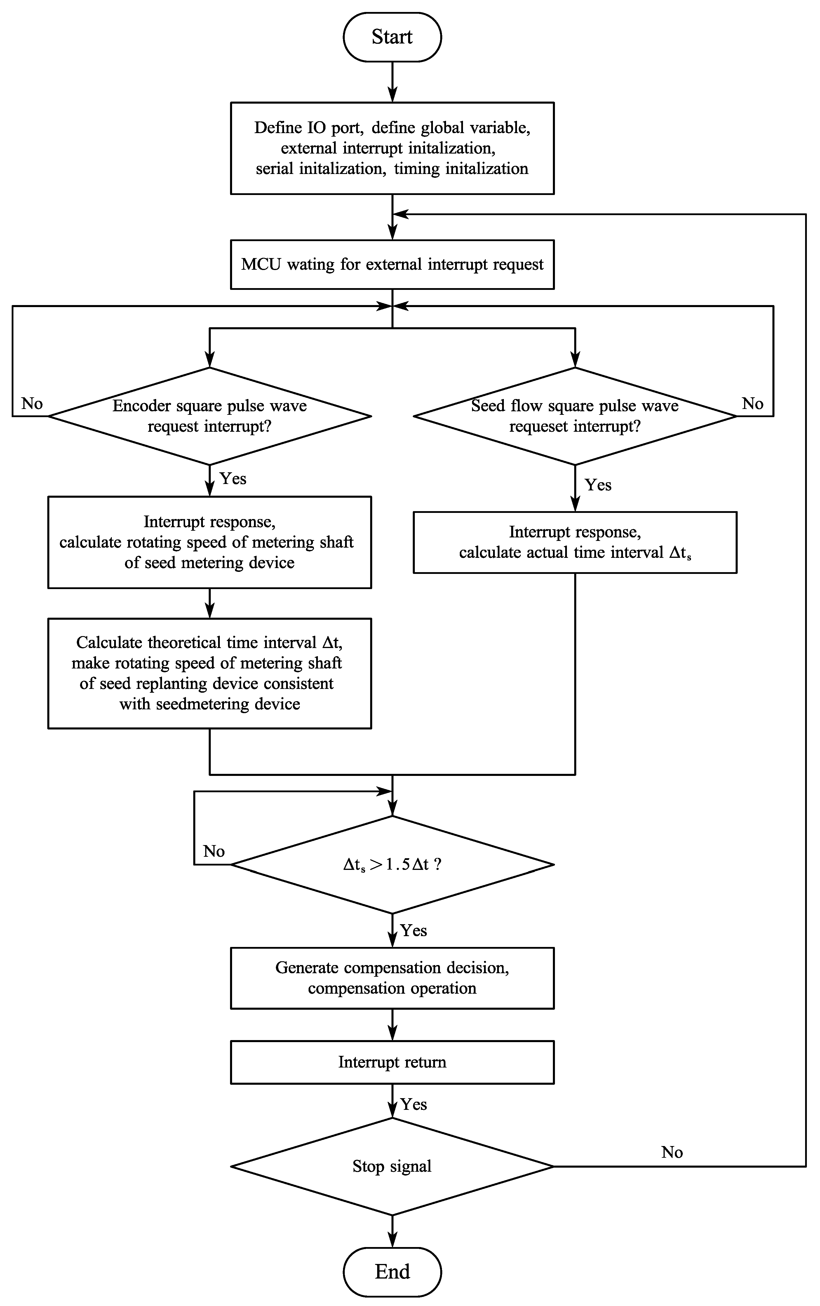
A compensation methodology utilizing rotational speed synchronization has been proposed, and a corresponding compensation control system has been designed. The approach has been implemented through the construction of a hardware system and the development of a microcontroller program.
iii.
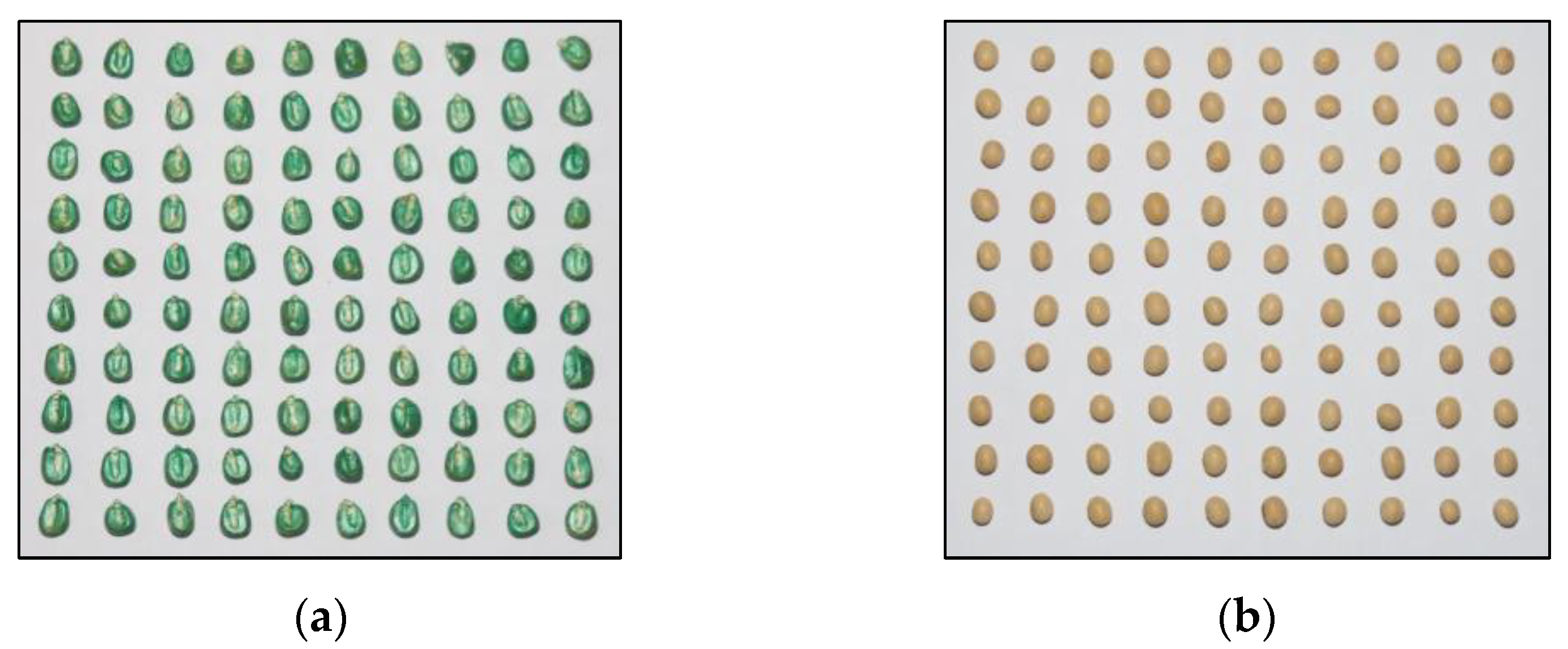
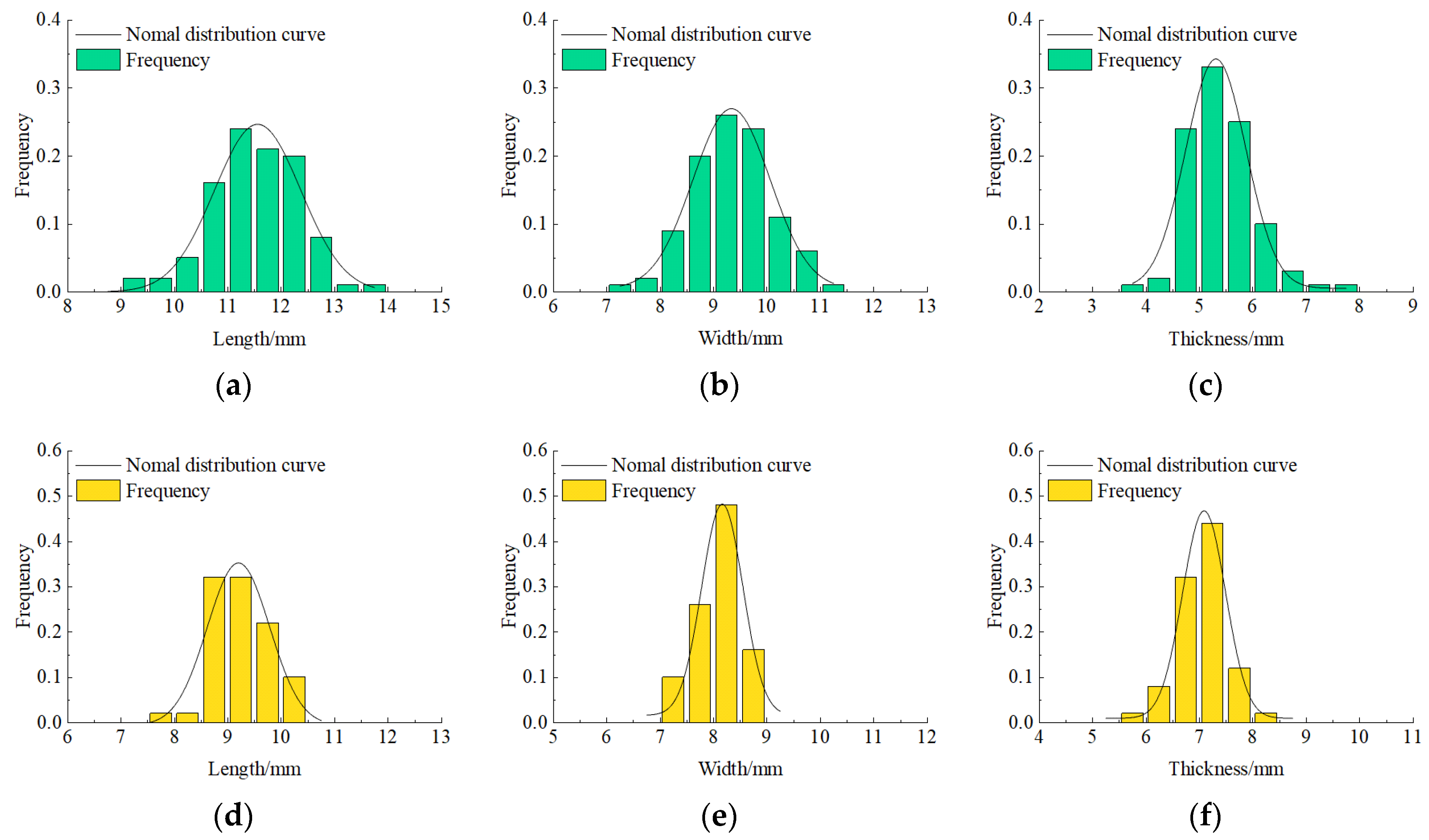
A single-factor test of seed filling performance was performed on the selected corn and soybean seed. The influence of various factors on seed filling performance was analyzed.
iv.
A Box–Behnken test of corn seed filling performance was conducted to further analyze the impact of various factors and their influence on corn seed filling performance. The comprehensive optimization of experimental factors was conducted to obtain the optimal combination of factors for corn seed filling performance.
v.
A verification test of seed feeding performance was performed on selected corn and soybean seeds. The seed feeding performance indexes for this system were compared to that described in previous articles to validate the effectiveness of this system.

2. Materials and Methods

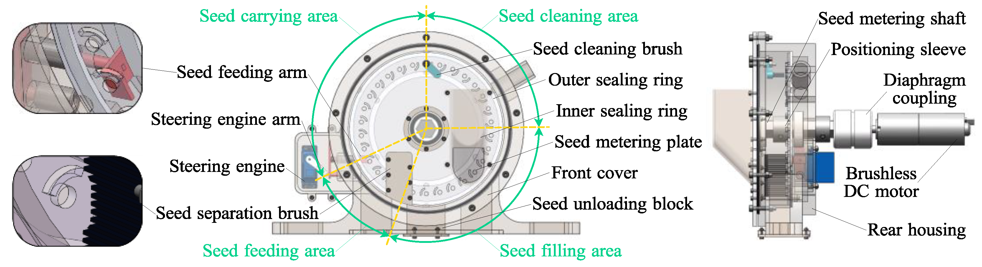
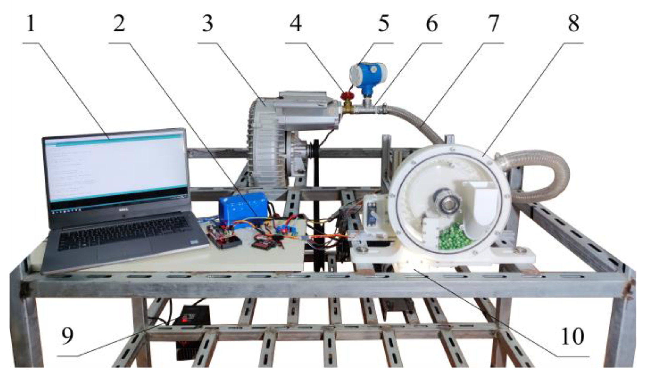
2.1. Overall Structure and Working Principle

A conventional compensation device is mainly transformed from the existing mechanical seed metering device. The conventional compensation device is driven by step motor, so it needs to be accelerated or started urgently during compensating operation, resulting in a reduction in working performance when the seeds shake off. In addition, the structural configuration cannot meet operation requirements under medium- and high-speed conditions (seeding speed is 8–12 km/h). In this study, the step motor was replaced by the brushless DC motor, which reduced the device vibration. At the same time, an independent seed feeding mechanism was designed to achieve controllable seed feeding. A pneumatic missed seeding automatic compensation device was designed. It is mainly composed of a seed unloading block, front cover, seed metering plate, inner sealing ring, outer sealing ring, seed cleaning brush, seed feeding arm, seed separation brush, steering engine, steering engine arm, positioning sleeve, seed metering shaft, rear housing, diaphragm coupling, and brushless DC motor. The overall structure is shown in Figure 1.
The working area of the compensation device can be divided into four stages: the seed filling area, the seed cleaning area, the seed carrying area, and the seed feeding area. During operation, the seed filling room is filled with the seeds from the seed box. The brushless DC motor transmits the power to the seed metering shaft through diaphragm coupling and drives the seed metering plate to rotate, keeping the rotating speed of the metering shaft of the seed compensation device synchronized with that of the seed metering device (corresponding to the same seeding speed). The seeds in the seed filling area are disturbed by the seed stirring bar on the seed metering plate, and the stable stack state of the seeds is broken. When the seeds are filled into the groove between the seed stirring bars, the seed enters the seed suction hole area. Under the effect of the air pressure difference between both sides of the seed suction hole, one or more seeds are sucked on the seed suction hole to complete the seed filling process. When the seed is moved to the seed cleaning area, the seed cleaning brush removes the excess seeds and completes the seed cleaning process. In the seed carrying area, the seeds stably sucked into the seed suction hole rotate with the seed metering plate to complete the seed carrying process. When the seed is moved to the seed feeding area, if there is miss-seeding, the seed feeding arm is driven by the steering engine to block the air flow. The seed is separated from the seed metering plate to complete the seed feeding process, and precision compensation is achieved. If there is no miss-seeding, the seed is still sucked onto the seed metering plate and returns to the seed filling area through the profiling gap on the seed separation brush.

2.2. Design of the Key Components

Among all components, the seed metering plate and the seed feeding arm are two of the key working components in the seed compensation device, and the rationality of the structure configuration directly affects the working quality of the compensation device.

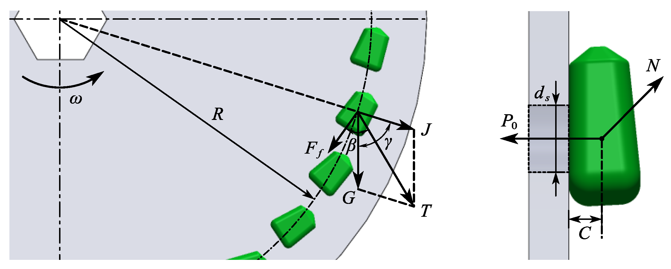
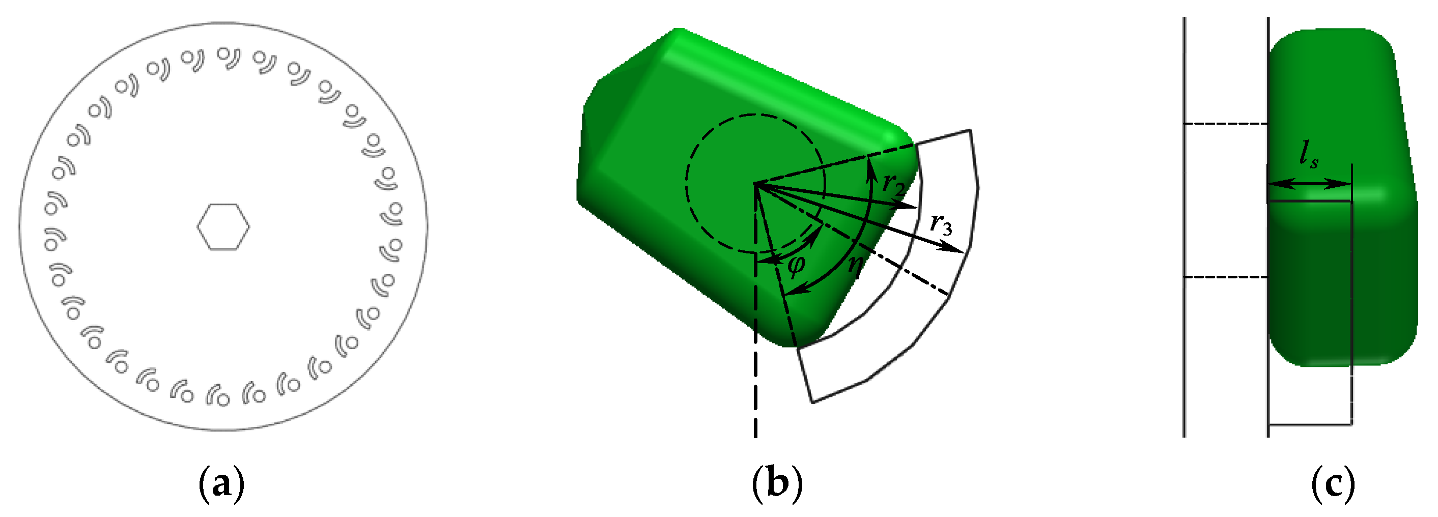
2.2.1. Seed Metering Plate

The seed’s physical properties are important factors for determining the design and working parameters of seed metering plate. The present study utilized Zhengdan-958 corn seeds and Zhonghuang-37 soybean seeds (which are prevalent in the corn–soybean rotation model in Northeast China) as the experimental materials. The Zhengdan-958 cultivar exhibits a late maturation pattern and has a growth period of approximately 120 days. The seeds are yellow in color and turn green upon chemical coating. Additionally, they possess a semi-horseshoe shape and are considered a superior feedstock due to their consistently high yields. The Zhonghuang-37 variety exhibits an early maturation period, with an average growth cycle of approximately 110 days. Its seeds are nearly elliptical and possess a yellow seed coat. In comparison to other early maturing varieties, Zhonghuang-37 showcases a higher average yield per unit area. One hundred samples were randomly selected to measure dimensions using an absolute origin digital caliper (Deli Group Co., Ltd., Ningbo, China, Deli DL91150 type) with a sensitivity of 0.01 mm (Figure 2). The thousand-seed mass was measured using an analytical balance (Changzhou Lucky Electronic Equipment Co., Ltd., Changzhou, China, Xingyun JA503 type) with an accuracy of 0.001 g.
The three-axis dimensions of corn and soybean seeds follow a normal distribution, as shown in Figure 3.
The main dimensions and thousand-seed mass of corn and soybean seeds are listed in Table 1.
It can be seen from Figure 2 that the corn seed is semi-horsetooth-shaped, and the soybean seed is oval. Table 1 reveals that the three-axis dimension parameters of corn samples were measured as follows: the average length was 11.51 mm, the average width was 9.31 mm, and the average thickness was 5.51 mm. The thousand seed mass of corn seed was 307.94 g. The three-axis dimension parameters of soybean samples were measured as follows: the average length was 9.21 mm, the average width was 8.05 mm, and the average thickness was 7.03 mm. The thousand seed mass of soybean seed was 273.20 g.
As the core component of the compensation device, the diameter of the seed metering plate is an essential factor affecting the overall structure of the compensation device and the pressure of the air chamber [29]. According to the relationship between the rotation speed of the seed metering plate and the seed filling time, the following can be obtained:
t f = l f v l f = α d 2 r 1 v = π n 30 d 2 r 1
where tf is the seed filling time, s; lf is the arc length of seed filling area, m; v is the linear velocity of suction hole center, m/s; α is the seed filling angle, rad; d is the diameter of seed metering plate, m; n is the rotation speed of seed metering plate, r/min; r1 is the radial distance between the suction hole center and the edge of seed metering plate, m.
According to Equation (1),
t f = 30 α π n
Equation (2) shows that the factors affecting the seed filling time t are related to the filling angle α and the rotation speed of the seed metering plate n. Moreover, the diameter of the seed metering plate has nothing to do with the retention time of the suction hole in the seed filling area. Considering the three-axis dimensions of corn and soybean and the seeding speed of 8–12 km/h, the diameter and thickness of the seed metering plate was set to 0.2 m and 3 mm, respectively.
The number of suction holes is an important factor to determine the rotation speed of seed metering plate. The planting density of corn is 6–8 plants/m2, and that of soybean is 16–20 plants/m2. According to the requirements of agronomic planting, the reasonable plant spacing range for precision seeding of corn is 0.18–0.22 m, while that for precision seeding of soybean is 0.08–0.1 m. In this study, the plant spacing for corn is set at 0.2 m, while that for soybean is set at 0.1m. When the diameter of seed metering plate is known to be 0.2 m, the calculation formula of the number of suction holes k is as follows:
k = 2 π v s v l p d 2 r 1 v = π n 30 d 2 r 1
where Vs is the advancing speed of the precision seeder, m/s; lp is the plant spacing, m.
According to Equation (3),
k = 60 v s n l p
It can be seen from Equation (4) that the number of suction holes is inversely proportional to the rotation speed of seed metering plate and is proportional to the advancing speed of the precision seeder. Considering factors such as seeding efficiency and dual-use of compensation device, and after ensuring that the linear velocity at the suction hole center of seed metering plate will not be too high, the number of suction holes k is determined to be 30. Figure 3 and Table 1 show that the length of corn seed is generally larger than that of soybean seed, so the circumferential arrangement radius of a suction hole is 85 mm, according to the maximum length of corn seed.
The diameter of a suction hole and the negative pressure intensity in the air chamber are important factors affecting the seed suction performance of the seed metering plate. A single corn seed sucked into suction holes was taken as the research object and subjected to force analysis, as shown in Figure 4.
If a suction hole can stably suck a single corn seed, the following equation holds:
H c = P 0 S S = π d s 2 4 P 0 = 2 C Q d Q = T 2 + F f 2 + 2 T F f c o s β T = G 2 + J 2 + 2 G J c o s γ J = m ω 2 R G = m g
where Hc is the vacuum degree of air chamber, Pa; P0 is the suction force of single suction hole, N; S is the cross-sectional area of suction hole, m2; ds is the diameter of suction hole, mm; Q is the resultant force of G, J and F, N; T is the resultant force of G and J, N; Ff is the friction between seeds, N; G is the gravity of a single seed, N; J is the centrifugal force on seeds, N; m is the mass of single seed, kg; ω is the angular velocity of seed metering plate, rad/s; R is the circumferential arrangement radius of suction hole, m; γ is the angle between G and J, °; β is the angle between T and Ff, °; g is the gravity acceleration, m/s2.
In the working process of the compensation device, the seeds collide with other seeds, and the seeds are also affected by machine vibration. Therefore, it is necessary to introduce seed suction reliability coefficient K1 (1.8–2.0) and external reliability coefficient K2 (1.6–2.0), and the following equation can be obtained:
H c = 8 K 1 K 2 C π d k 2 G 2 + J 2 + 2 G J c o s γ + F f 2 + 2 G 2 + J 2 + 2 G J c o s α F f c o s α F f c o s β
At maximum limit conditions, cos γ = cos β = 1; therefore, according to Equation (6),
H c m a x = 8 K 1 K 2 C G π d k 2 1 + 1 g v 2 R + λ
In this equation, Hcmax is the maximum critical vacuum degree of air chamber, Pa; λ is the comprehensive coefficient of seed friction resistance; K1 is the seed suction reliability coefficient; K2 is the external reliability coefficient.
Equation (7) shows that the factors affecting the vacuum degree of air chamber Hcmax are related to the seed’s physical properties, the diameter of suction holes, the rotation speed of seed metering plate, and the circumferential arrangement radius of suction holes. If the suction hole is too small, a higher vacuum degree of the suction chamber is required to ensure that the seeds are stably sucked into the suction hole. On the contrary, if the suction hole is too large, the suction hole cannot be fully covered by a single seed, increasing the probability of multiple seeds being adsorbed on the suction hole. Therefore, based on the average width of corn seeds and soybean seeds and previous studies, the diameter range of suction holes was determined to be 4.5–6.5 mm. The shape of corn seeds is irregular, and the fluidity of corn seeds in seed filling area was poor; therefore, the comprehensive coefficient of seed friction resistance was large. In order to keep the corn seed stable on the suction hole, the actual internal vacuum should be greater than Hcmax. If the vacuum degree cannot meet the suction requirements for seed filling, the missing filling quantity will increase dramatically. Considering the collision of seeds and the vibration of the machine, combined with the previous research, it was determined that the vacuum degree of the gas chamber was higher than 3 kPa. The vacuum degree is an important factor affecting the working performance of the compensation device. The greater the vacuum degree, the stronger the suction of the suction hole, thus reducing the probability of miss-filling. However, too much suction will increase the probability of a single suction hole sucking multiple seeds. In addition, the vacuum degree is not only affected by various resistance factors in the process of seed suction but also affected by airflow fluctuation and machine vibration in the actual operation process. Therefore, the vacuum degree of the air chamber during actual operation should be slightly greater than the calculated theoretical value. For corn seeds, the vacuum degree was determined to be 3–5 kPa. According to the “Agricultural Machinery Design Manual” [30], the vacuum degree range for soybean seeds is basically the same as that for corn seeds, so the vacuum degree range for corn seeds in this study is also applicable to soybean seeds.
Single-seed filling is an important part of precision seeding of large- and medium-sized grain crops. The shape of corn seeds is irregular, and the size variation coefficient is large; thus, the seeds in the seed filling area can easily form a stable accumulation area. The seed fluidity in the stable accumulation area was poor, which is not conducive to single-seed filling. Therefore, a seed stirring bar was designed, which can make the stacked seeds produce a boiling movement, improving the fluidity of the seeds in the seed filling area. It should be noted that the posture of seeds on suction holes is also an important factor affecting the stability of seed filling. According to the existing literature, effective seed filling is obtained when the contact area between the seed and the suction hole is the largest, and the seed position is relatively stable [31]. The contact area between the lying posture of corn seeds and the suction hole is the largest, as shown in Figure 4; therefore, the seed stirring bar should help to increase the proportion of seed lying position of the seeds during filling. The image collected along the corn seed thickness direction (Figure 2a) was binarized and the seed contour was extracted, as shown in Figure 5.
As can be seen in Figure 5, the parabola has the highest fit with the bottom of corn seed contour. However, it is clear to see that the arc has better compatibility with the bottom contour of corn seeds. Due to the large coefficient of variation of corn seed size, the compatibility between the seed stirring bar and corn seed is more important. Therefore, the inner contour of the seed stirring bar is determined to be the concentric arc of the suction hole, as shown in Figure 6.
The radius of the inner contour arc of the seed stirring bar is determined by the average length of the corn seed, which is about half of the average length of the corn seed, and r2 was set to 6 mm. Considering the processing accuracy and material strength, the radius of the outer contour arc of the seed stirring bar was set to 8mm. The central angle of the arc of the seed stirring bar was determined by the average width of the corn seed. In order to ensure that the seed stirring bar has better compatibility, η was set to 90°. The included angle between the center line of the arc of the seed stirring bar and the connecting line between the suction hole center and the seed metering plate center is the critical parameter in determining the position of the seed stirring bar. It should make the seed stirring bar have a better disturbing effect in the seed filling area and not affect the seed falling track during seed feeding; thus, φ was set to 60°. The parameters of η and φ were determined based on the suction hole in the vertical direction of the rotation plane of the seed metering plate. The thickness of seed stirring bar is determined by the thickness of corn seed, which is a critical factor affecting the working performance of seed stirring bar. If the seed stirring bar is too thin, the ability to disturb the seeds in the filling area will be limited. On the contrary, if the seed stirring bar is too thick, the probability of seed jamming and seed damage will increase. According to the distribution of corn seed thickness, the thickness range of seed stirring bar was determined to be 2–4 mm. Although the shape of soybean seeds was relatively regular, and considering the fact that they do not need to be sucked on the suction hole in a specific position, the fluidity of soybean seeds in the seed filling area needed to be improved. Consequently, the seed stirring bar is also very important to soybean seeds.
In summary, the range of suction hole diameter was determined to be 4.5–6.5 mm, the range of agitator strip thickness was determined to be 2–4 mm, and the range of negative pressure was determined to be 3–5 kPa. These ranges of important parameter values provided the basis for parameter range selection in single-factor tests.

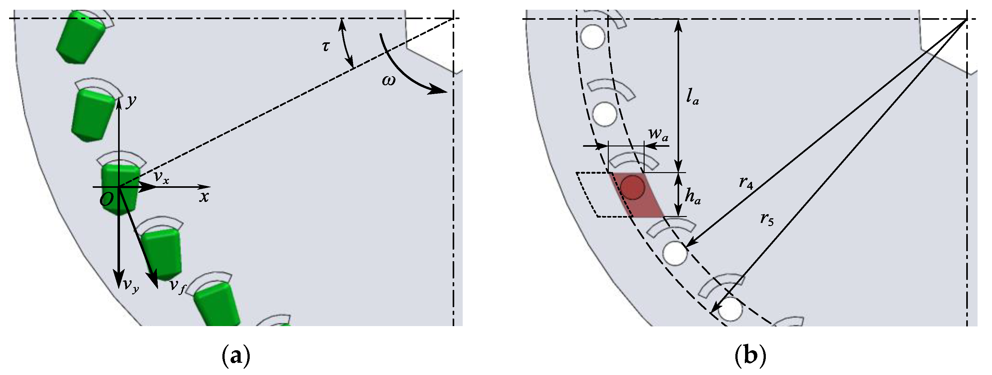
2.2.2. Seed Feeding Arm

As another core component of the compensation device, the seed feeding arm is a key component that ensures controllable seed feeding. A reasonable seed feeding position can effectively improve seed feeding quality. The seed feeding position of the compensation device is determined by the structure of the seed feeding arm. Therefore, it is necessary to carry out kinematic analysis of seed feeding process, as shown in Figure 7a.
With the seed centroid O as the origin, the xOy rectangular coordinate system is established on the rotation plane of the seed metering plate, and the equation of the seed motion trajectory can be obtained as follows:
X = v x t Y = v y t + g t 2 2 v x = v sin τ v y = v cos τ v f = n π R 30
where X is the horizontal displacement of the seed, mm; Y is the vertical displacement of the seed, mm; vx is the horizontal component of the seed feeding velocity, m/s; vy is the vertical component of the seed feeding velocity, m/s; τ is the seed feeding angle, °; t is the seed feeding time, s; vf is the seed feeding velocity, m/s.
According to Equation (8),
X = n π R s i n τ 30 t Y = n π R c o s τ 30 t + g t 2 2
In order to ensure the seed feeding quality, the seed cannot collide with adjacent seed stirring bars in the process of separating from suction hole, and the following conditions should be met:
n π R c o s τ 30 t s + g t s 2 2 > R 1 c o s ρ ρ = n π t s 30
where ρ is the corner of the seed metering plate during the seed separation from the suction hole, °; ts is the time required for the seed to separate from the suction hole, s.
The analysis of seed feeding motion shows the seed motion track related to the rotation speed of seed metering plate when the structural parameters of seed metering plate are determined. The seed feeding angle τ was set to 25°, and the maximum rotation speed of the seed metering plate was 66.67 r/min (corresponding to a soybean seeding speed of 12 km/h). According to Equation (10), it can be concluded that the time required for the seed to separate from the suction hole is less than 1 × 10⁻⁴ s, which meets the requirements of seed feeding quality.
When the seed feeding operation is carried out, the seed feeding arm completely blocks the airflow of the suction hole and can only affect a single suction hole. When seed feeding is not required, the seed feeding arm does not block all suction holes and does not interfere with the air chamber shell. Therefore, the structural parameters of the seed feeding arm meet Equation (11).
l a R sin τ d s 2 d s w a < r 6 R c o s τ d s 2 d s h a < R s i n τ + 360 ° k 3 d s 2 R s i n τ d s 2 R d s 2 r 4 r 5 r 6
where wa is the width of the seed feeding arm, mm; la is the vertical distance from the upper edge of the seed feeding arm to the center of the seed metering plate, mm; ha is the vertical height of the feeding arm, mm; r4 is the radius of the arc of the inner contour of the seed feeding arm, mm; r5 is the radius of the arc of the outer contour of the seed feeding arm, mm; r6 is the radius of the arc of the outer contour of the air chamber, mm.
The radius of the arc of the outer contour of the air chamber is 95mm. The values of related parameters are substituted into Equation (11) so that the following structural parameters of seed feeding arm can be determined: la ≤ 32.67 mm, 6.50 mm ≤ wa ≤ 7.78 mm, 6.50 mm ≤ ha ≤ 8.73 mm, r4 ≥ 81.75 mm, r5 ≤ 95 mm. Therefore, the vertical distance from the upper edge of the seed feeding arm to the center of the seed metering plate was set to 32.5 mm, the width of the seed feeding arm was set to 7.5 mm, the vertical height was set to 8.5 mm, the arc radius of the inner and outer contour of the seed feeding arm was set to 90 mm.

2.3. Design of the Compensation Control System

The hardware and software systems of the compensation control system were designed to accurately compensate the single-seed missed seeding or continuous seed missed seeding in the metering process of the corn and soybean precision seed metering device.

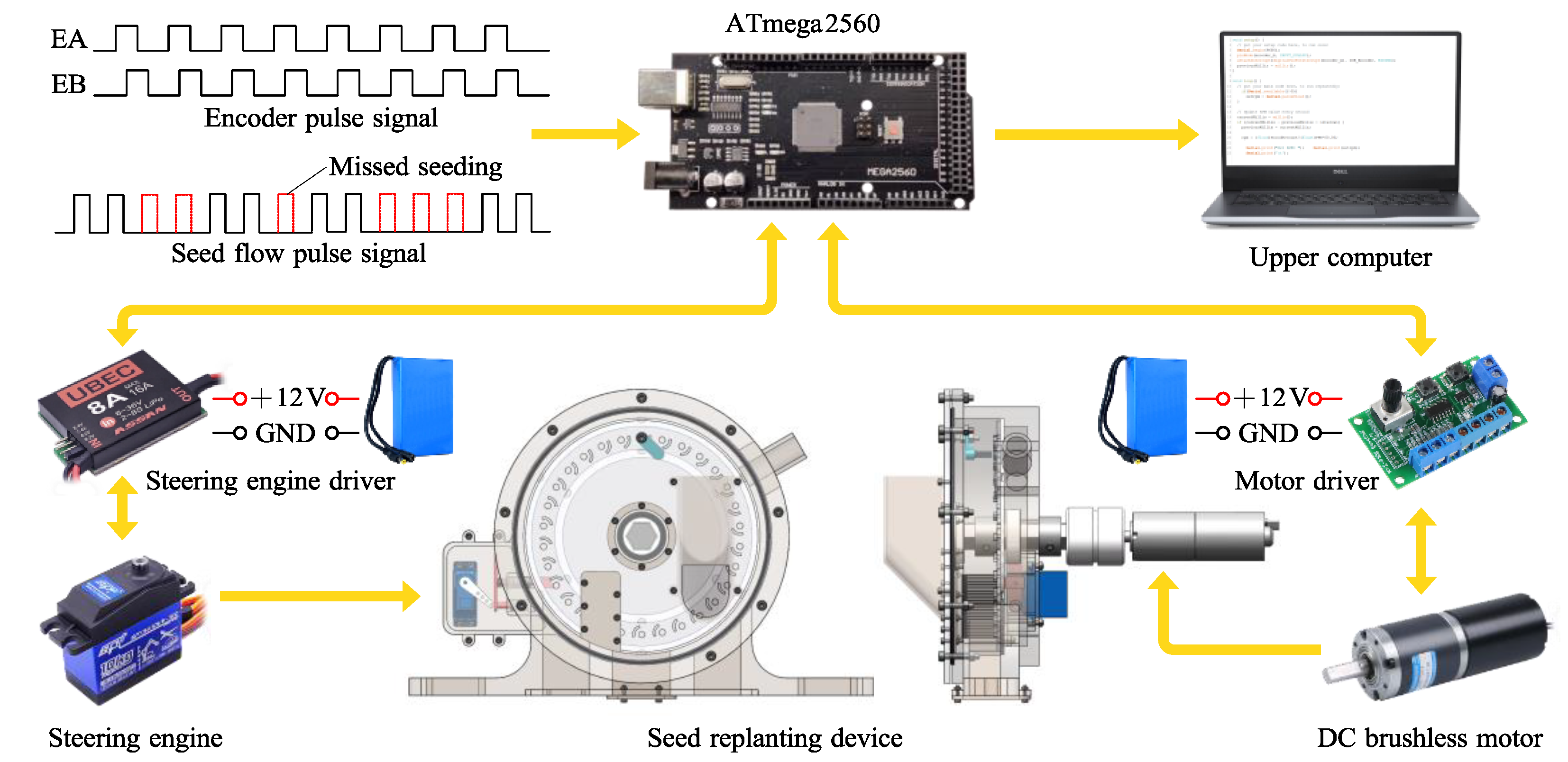
2.3.1. Hardware Design

The hardware system was mainly composed of a circuit board integrating ATmega2560 master chip, universal serial bus (USB) to transistor-transistor logic (TTL) chip, upper computer, steering engine driver, steering engine, motor driver, and DC brushless motor, as shown in Figure 8. Each part was electrically connected through communication lines (the signal lines and the power lines) to complete the information exchange. Among these components, the power lines are used for power supply and form connections between each piece of equipment, where the power supply is the direct current (DC) 12 V lithium battery. The seed flow signal of the seed metering device was processed into pulse signal by the photoelectric sensing system. The single-chip external interrupt (interrupt 0) was configured to falling edge trigger mode, and the corresponding input/output (IO) port was set as the input pullup mode. Thus, the pulse signal was obtained, and the seeding parameters were calculated. At the same time, this system cooperated with the incremental photoelectric encoder installed on the seed metering shaft of seed metering device, and the rotating speed of the metering shaft of the metering device was monitored. Based on the rotating speed of the metering shaft of the metering device monitored by the incremental photoelectric encoder, the single-chip drives the DC brushless motor through the motor driver to make the rotating speed of the metering shaft of the compensation device synchronized with that of the seed metering device, and the theoretical time interval between two adjacent seeds is calculated. Missed seeds occur with system monitoring when the actual time interval between adjacent seeds is greater than 1.5 times the theoretical time interval. At this time, the single-chip microcomputer drives the steering engine through the steering engine driver to make the feeding arm block the air flow, and compensation is achieved. The data detected by the photoelectric sensing system and incremental photoelectric encoder were transmitted to the ATmega2560 single- chip microcomputer (Microchip Technology Incorporated, State of Arizona, America, ATmega2560-16CU type) through the signal line for control and calculation, and the serial port signal was collected by the upper computer through the USB to TTL chip to obtain the seeding information.

2.3.2. Software Design

In this study, a single-chip microcomputer program was developed and designed using the C/C++ language (Arduino IDE 1.8.19) to control the compensation control system. This program receives square pulse wave signals from the photoelectric sensing system and incremental photoelectric encoder, evaluates the time interval between adjacent pulses, generates compensation decisions, and ultimately drives the relevant hardware to execute the compensation operation. A program flow chart of the single-chip microcomputer is shown in Figure 9. After the single-chip microcomputer was activated, the program was initialized, and relevant IO ports and variables were defined, including initializing the external interrupt port, serial port, and timing port.
After initialization, the single-chip microcomputer entered the external interrupt request state. When the encoder square pulse wave was applied as the interrupt source to request external interruption, the single-chip microcomputer responded to this interruption and calculated the rotating speed of the metering shaft of the seed metering device. The single-chip microcomputer calculated the theoretical time interval between adjacent seeds and made the rotating speed of the metering shaft of the compensation device synchronized with that of the seed metering device. In order to determine the sequence of receiving signals, the priority of receiving interrupt was set. The priority of seed flow signal receiving interrupt is higher than that of encoder signal receiving interrupt. Therefore, the seed flow signal was received preferentially by the single-chip microcomputer. When the seed flow square pulse wave was applied as the interrupt source to request external interruption, the single-chip microcomputer responded to this interruption. First, the actual time interval between adjacent pulses was calculated and compared to the theoretical time interval. Then, the program judged whether the actual seed spacing was missing. If so, the compensation decision was generated and the compensating operation was completed. Finally, the single-chip microcomputer determined whether the stop signal was received. If the stop signal was received, the program stopped; otherwise, it entered the next cycle.

2.4. Experiment

To investigate the effect of influencing factors on working performance of the compensation system, a bench test was built according to GB/T6973-2005 “Experiment method of single seed (Precision) seeder.” For the tests, a self-built compensation system performance test bench was utilized, as depicted in Figure 10. The fan was powered by a three-phase asynchronous motor and its speed could be infinitely adjusted using a frequency transformer. A pipe equipped with regulating valves and tee joints was connected between the fan and the compensation device. The detection end of the digital pressure gauge was threaded with the tee joint, which enabled the real-time detection and display of the pipe pressure. The air pressure in the compensation device could be regulated by adjusting the regulating valves. Additionally, the OnePlus camera (Shenzhen Oneplus Technology Co., Ltd., Shenzhen, China, 9R type, 480 fps) was positioned towards the seed carrying area to record the real-time adsorption state of seeds on the suction hole’s end surfaces, enabling the evaluation of the seed filling performance of the compensation device. The performance monitoring system of the large and medium-sized grain crop metering device improved for the compensation device is installed at the seed drop port corresponding to the seed feeding area to evaluate the seed feeding performance of compensation device.
The preliminary analysis and pre-tests revealed that the key factors affecting the seed filling effect were the suction hole diameter, seed stirring bar thickness, and negative pressure. Therefore, the single factor test of seed filling performance tests were carried out with the above three factors as the impact factors. In order to verify the seed filling performance of the compensation device under medium- and high-speed conditions, the seeding speed was adjusted to 10 km/h. Under stable operating conditions, the camera was utilized to capture the stable adsorption state of seeds in the seed carrying area. One video was recorded for each experimental group. A total of 251 consecutive suction holes were randomly selected from the video, and the number of seeds adsorbed on their end surfaces was recorded separately. Multiple filling was considered to occur when more seeds were adsorbed on the end surface of the suction hole, while missed filling was recorded when no seed was adsorbed. Taking the seed filling qualified rate, Q0; multiple rate, M0; and missed rate, E0 as evaluation indexes, the calculation formula is as follows:
Q 0 = n 1 N × 100 % M 0 = n 2 N × 100 % E 0 = n 3 N × 100 %
where n1 is the suction holes number of one seed adsorbed on the end surface; n2 is the suction holes number of 2 or more seeds adsorbed on the end surface; n3 is the suction holes number without seed adsorbed on the end surface; and N is suction holes total number.
The diameter of suction holes was set to 4.5–6.5 mm, with an interval of 0.5 mm, and the single-factor test of the diameter of suction holes was performed at a thickness of 3 mm seed stirring bar and a 4 kPa negative pressure. To perform the single-factor test of the thickness of seed stirring bar, the diameter of suction hole was set as 5.5 mm, the negative pressure was set as 4 kPa, and the thickness of seed stirring bar was set as 2.0–4.0 mm, with an interval of 0.5 mm. In order to improve the filling effect, a fan is required to provide appropriate negative pressure for seed filling. Therefore, the single factor test was performed at the negative pressure of 3.0–5.0 kPa, with an interval of 0.5 kPa, a diameter of 5.5 mm suction hole, and a thickness of 3 mm seed stirring bar. Each set of tests was replicated 3 times, and the mean values were recorded as the evaluation indicators.
To deeply analyze the effects of various factors and their interaction terms on the corn seed filling performance index and obtain the optimal working parameter combination, the Box–Behnken central composite design principle was used. The factors and working range were selected according to the single factor test results. A total of 17 groups were tested, with each group being replicated 3 times. The mean values were recorded as evaluation indices.
A seed feeding performance verification test was carried out at different seeding speeds, and the simulated encoder square pulse wave signal corresponding to each speed was sent to the compensation control system to ensure the stable operation of the compensation device. The simulated seed flow square pulse wave containing 125 discontinuous missed seeding signals was sent to the compensation control system to verify the single seed feeding performance of the compensation device. When the compensation control system responded to the missed seeding signal and the photoelectric sensor system detected a single seed, we considered it an effective single seed feeding. The time from the response of the compensation control system to the missed seeding signal to the detection of a single seed by the photoelectric sensor system was defined as the single seed feeding time, which was recorded as an important evaluation index. The simulated seed flow square pulse wave containing 251 continuous missed seeding signals was sent to the compensation control system to verify the continuous seed feeding performance of the compensation device. When the compensation control system responds to the missed seeding signal and the photoelectric sensing system detected that the actual time interval between adjacent seeds was 0.5–1.5 times of the theoretical time interval, we considered that to be qualified feeding. If the actual time interval was smaller than or equal to 0.5 times the theoretical time interval, multiple feeding occurred. If the actual time interval was larger than 1.5 times the theoretical time interval, missed feeding ensued. For Zhengdan-958 corn seeds, the parameters of the compensation device were based on the optimal parameter combination obtained from the previous orthogonal test. For Zhonghuang-37 soybean seeds, the parameters of the compensation device were based on the optimal parameter combination obtained from the previous single-factor test. The seeding speed was set as 8–12 km/h, with an interval of 1 km/h. Each group was replicated 3 times, and the mean values were recorded as evaluation indices. Taking the effective single feeding rate, S1; average single feeding time, T1; seed feeding qualified rate, Q1; multiple feeding rate, M1; and missed feeding rate, E1; as evaluation indexes, the calculation formula is as follows:
S 1 = n 0 N 1 × 100 % T 1 = t 0 n 0 Q 1 = n 4 N 2 × 100 % M 1 = n 5 N 2 × 100 % E 1 = n 6 N 2 × 100 %
where n0 is the number of effective single seed filling; t0 is the single seed feeding time, s; n4 is the number of qualified seed feeding; n5 is the number of multiple seed feeding; n6 is the number of missed seed feeding; N1 is the total number of discontinuous missed seeding signals; N2 is the total number of continuous missed seeding signals.

3. Results and Discussion

3.1. Single Factor Test on Seed Filling Performance

The test results of the effects of different factor levels on the seed filling performance of compensation device are shown in Figure 11. The horizontal coordinate in the figure is the level of each factor, and the vertical coordinate is the test evaluation index.
As can be seen from Figure 11a, for both corn seed and soybean seed, an increase in suction hole diameter resulted in an initial increase followed by a decrease in the qualified filling rate, while the multiple filling rate gradually increased and the missed filling rate gradually decreased. This indicates that a smaller suction hole diameter requires a larger vacuum in the air chamber, which can adversely affect the normal adsorption of seeds. The suction hole diameter was larger, leading two or more smaller corn seeds being adsorbed on one suction hole. The seed cleaning brush found it difficult to clean these seeds, resulting in multiple seed filling.
As can be seen from Figure 11b, for corn seed, an increase in seed stirring bar thickness resulted in an initial increase followed by a decrease in the qualified filling rate, while the multiple filling rate gradually increased and the missed filling rate gradually decreased. This indicates that the corn seed filling performance was improved, with there being an increase in seed stirring bar thickness. However, the larger thickness of the seed stirring bar caused two or more seeds to be stuck between the two seed stirring bars, resulting in an increase in the multiple filling rate. For soybean seed, the qualified filling rate and multiple filling rate both initially increased and then stabilized with the increase in seed stirring bar thickness, and the missed filling rate initially stabilized and then increased. This showed that the soybean seed filling performance improved when the seed stirring bar thickness was increased. When the seed stirring bar thickness was larger than 3mm, the three indexes of soybean seed filling performance had little overall change, indicated that an excessively thick seed stirring bar had no significant effect on soybean seed filling performance.
For both corn seed and soybean seed, an increase in negative pressure resulted in an initial increase followed by a decrease in the qualified filling rate, while the multiple filling rate gradually increased and the missed filling rate gradually decreased. This showed that, when the negative pressure was 3 kPa, the wind pressure was smaller and the seeds could not be stably adsorbed on the suction hole, resulting in a higher missed filling rate. When the negative pressure increased to 5 kPa, the negative pressure was larger, two or more seeds were adsorbed on the suction hole, and the seed cleaning performance was affected, resulting in a higher multiple filling rate.

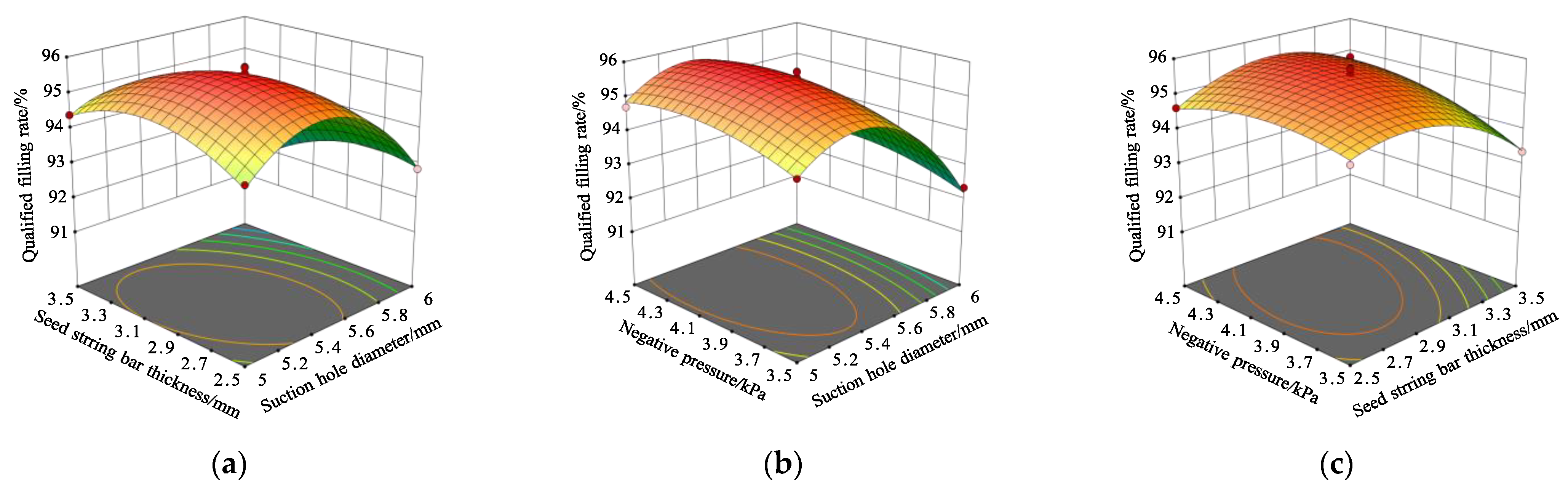
3.2. Box–Behnken Test on Corn Seed Filling Performance

Box–Behnken response method was used to design the orthogonal test. The test program included 17 test points, including 12 analysis factor points and 5 zero-point estimation errors. The coding of test factors and levels are shown in Table 2.
The protocol and results of the Box–Behnken test are shown in Table 3.
The Design-Expert 10.0.4 software was employed to conduct further significance analysis, and the results are presented in Table 4. From the table, it can be seen that the terms of the regression models were all highly significant and the terms of lack of fit were all insignificant, thus indicating that the regression equations fitted well with the actual situation. Regarding the regression equations of qualified filling rate, the interaction term X1×3 was found to be insignificant, while the remaining terms were highly significant. The order of each test factor affecting the qualified filling rate was as follows: suction hole diameter > seed stirring bar thickness > negative pressure. Regarding the regression equations of multiple filling rate, the interaction term X1X2, the quadratic terms X32, and all the linear terms X1, X2, and X3 were highly significant, while the remaining terms were insignificant. The order of each test factor affecting multiple filling rate was as follows: suction hole diameter > seed stirring bar thickness > negative pressure. Regarding the regression equations of missed filling rate, the interaction term X2X3, the quadratic terms X12 and X22, and the linear terms X1 and X3 were highly significant, while the remaining terms were insignificant. The order of each test factor affecting missed filling rate was as follows: negative pressure > suction hole diameter > seed stirring bar thickness. The insignificant terms were eliminated, and the three models were optimized on the basis of ensuring that the models were significant. The quadratic regression equations of evaluation indexes with test factors are as follows:
Q 0 = 95 . 55 1 . 05 X 1 0 . 31 X 2 + 0 . 28 X 3 0 . 48 X 1 X 2 + 0 . 37 X 2 X 3 1.62 X 1 2 0 . 79 X 2 2 0 . 39 X 3 2
M 0 = 2 . 84 + 0 . 69 X 1 + 0 . 35 X 2 + 0 . 27 X 3 + 0 . 53 X 1 X 2 + 0 . 13 X 3 2
E 0 = 1 . 61 + 0 . 36 X 1 0 . 54 X 3 0 . 52 X 2 X 3 + 1 . 74 X 1 2 + 0 . 66 X 2 2
In order to visually analyze the effect of interaction factors on corn seed filling performance, a descending dimension method was employed to set the coding of any one of the three impact factors to zero. The corresponding response surface diagrams depicting the interaction of the remaining two impact factors on the qualified filling rate were then plotted. Please refer to Figure 12 for a visual representation of the results.
As can be seen from Figure 12a, under the condition that the negative pressure was 4.0 kPa and the suction hole diameter was constant, the qualified seed filling rate was the first to increase and then decrease with increasing seed stirring bar thickness. Under the condition that the negative pressure was 4.0 kPa and the seed stirring bar thickness was constant, the qualified seed filling rate was the first to increase and then decrease with increasing suction hole diameter. According to the contour curve, when the diameter of suction hole was 5.2~5.6 mm and the thickness of stirring bar was 2.7~3.1 mm, the qualified seed filling rate had a maximum value.
As can be seen from Figure 12b, under the condition that the seed stirring bar thickness was 3.0 mm and the suction hole diameter was constant, the qualified seed filling rate was the first to increase and then decrease with increasing negative pressure. Under the condition that the seed stirring bar thickness was 3.0 mm and the negative pressure was constant, the qualified seed filling rate was the first to increase and then decrease with increasing suction hole diameter. According to the contour curve, when the diameter of suction hole was 5.2~5.6 mm and the negative pressure was 3.9~4.3 kPa, the qualified seed filling rate had a maximum value.
As can be seen from Figure 12c, under the condition that the suction hole diameter was 5.0 mm and the seed stirring bar thickness was constant, the qualified seed filling rate was the first to increase and then decrease with increasing negative pressure. Under the condition that the suction hole diameter was 5.0 mm and the negative pressure was constant, the qualified seed filling rate was the first to increase and then decrease with increasing seed stirring bar thickness. According to the contour curve, when the seed stirring bar thickness was 2.7~3.1 mm and the negative pressure was 3.9~4.3 kPa, the qualified seed filling rate had a maximum value. Meanwhile, the variation magnitude of response surface in Figure 12 indicates that the influence of the suction hole diameter on the qualified seed filling rate was significantly greater than that of the seed stirring bar thickness and negative pressure—consistent with the previous variance analysis.
In order to determine the optimal combination of operating parameters for the aforementioned test factors, the optimization objectives were set as the maximization of qualified seed filling rate and minimization of multiple and missed seed filling rates. The range of test factors were established as boundary conditions, and the regression models were optimized for the optimal solution. The objective functions and boundary conditions can be expressed as follows:
max Q 0 X 1 , X 2 , X 3 min M 0 X 1 , X 2 , X 3 min E 0 X 1 , X 2 , X 3 s . t 5.0   mm X 1 6.0   mm 2.5   mm X 2 3.5   mm 3.5   kPa X 3 4.5   kPa
The optimal solution yielded the following parameter values: 5.3 mm for suction hole diameter, 2.9 mm for seed stirring bar thickness, and 4.1 kPa for negative pressure. The corresponding seed filling performance metrics were as follows: 95.73% for qualified seed filling rate, 2.54% for multiple seed filling rate, and 1.73% for missed seed filling rate. Validation tests were conducted based on the optimized parameter values to assess reliability. The tests were repeated three times, and the mean values of the evaluation indexes were 95.46% for qualified seed filling rate, 2.47% for multiple seed filling rate, and 2.07% for missed seed filling rate. These results are consistent with the predicted results.

3.3. Verification Test on Seed Feeding Performance

For corn seeds, based on the optimal parameters obtained through orthogonal experiments, the suction hole diameter was set to 5.3 mm, the seed stirring bar was set to 2.9 mm, and the negative pressure was set to 4.1 kpa to verify the seed feeding performance of the compensation system. For soybean seeds, based on the optimal parameters obtained from a single factor experiment, the suction hole diameter was set to 5.0 mm, the seed stirring bar was set to 3.0 mm, and the negative pressure was set to 3.5 kPa to verify the seed feeding performance of the compensation system. The results of the verification test are shown in Table 5.
As can be seen from Table 5, for both corn and soybean seeds, the effective single feed rate and the qualified feed rate gradually decreased, and the missed feed rate gradually increased with increasing seeding speed at the optimal combination of parameters. For corn seeds, when the seed speed is within the range of 8 to 12 km/h, the effective single feeding rate is greater than 88%, the average single feeding time is less than 0.18 s, the qualified feeding rate is greater than 90%, the multiple feeding rate is less than 3%, and the missed feeding rate is less than 7%. For soybean seeds, when the seeding speed is within the range of 8 to 12 km/h, the effective single feeding rate is greater than 85%, the average single feeding time is less than 0.17 s, the qualified feeding rate is greater than 86%, the multiple feeding rate is less than 4%, and the missed feeding rate is less than 10%. The above performance indicators can meet the agronomic requirements for precision seeding of corn and soybean.

3.4. Discussion

As the most widely used pneumatic seed metering device, the automatic compensation method for missed seeding of large- and medium-sized grain crop metering devices is of great value to promote the development of the sowing aspect of precision agriculture. The conventional mechanical automatic compensation device for missed seeding has poor motor acceleration performance and slow system response, thus reducing seed feeding performance. In addition, the structural configuration cannot meet the operational requirements under medium- to high-speed working conditions. The feeding performance of the pneumatic automatic compensation device for missing seeds of large- and medium-sized grain crops based on rotational speed synchronization can be compared with those found in previous studies. Several researchers have developed compensation systems to improve the qualified seeding rate of corn no-till planters [27] and those systems can be considered for comparison with the proposed system. The average effective single feeding rate of the compensation system in [27] was 91.0% at a speed of 5 to 7 km/h; however, the results of this study at a working speed of 8 to 12 km/h was 92.65%. In [27], the effective single feeding rate of the missed seeding compensation system gradually decreased as the seeding speed increased, and when the seeding speed was 7 km/h, the effective single feeding rate was only 89.32%; nevertheless, when the compensation system in this study operates at a speed of 11 km/h, the effective single feeding rate is higher than 90%. The proposed system outperforms the system reported in a previous study in terms of single seed feeding performance. In particular, the greatest improvement can be seen in the medium- and high-speed adaptability. The results of this study regarding the previously unmentioned seed feeding response time and continuous seed feeding performance are satisfactory, as they meet the performance requirements for seeding corn and soybeans under medium- to high-speed operating conditions.
This study demonstrates the feasibility of using a compensation method based on rotational speed synchronization and pneumatic seed filling to improve the performance of the large- and medium-sized grain crop missed seeding compensation system under medium- and high-speed conditions. The hardware and software design of the compensation system and the influence of the relevant test factors on the working performance obtained in the paper can act as a reference for the design and parameter optimization of the automatic compensation system for missed seeding of large- and medium-sized grain crop seeding devices. Despite the promising results reported in the present study, this study has certain limitations that should be taken into account. For instance, only corn and soybean seeds were considered in the optimization process, and further investigation is required to determine the optimal operating parameters for large- and medium-sized grain crop seeds of different varieties.

4. Conclusions

  • This study aims to address the issue of poor performance in automatic compensation systems for missing seeds of large- and medium-sized grain crops under medium- and high-speed conditions. To achieve this, a pneumatic automatic compensation system was designed based on rotational speed synchronization. The system’s key structure and parameters were determined through theoretical analysis and operational requirements. Furthermore, the hardware and software systems of the compensation control system were designed according to the compensation requirements.
  • The optimal parameters for corn seed filling were determined through single-factor tests and the Box–Behnken Design test. The recommended parameter values are a suction hole diameter of 5.3 mm, a seed stirring bar thickness of 2.9 mm, and a negative pressure of 4.1 kPa. Validation tests were conducted using these parameters, and the resulting evaluation indices were 95.46% for qualified seed filling rate, 2.47% for multiple seed filling rate, and 2.07% for missed seed filling rate.
  • The seed feeding performance verification test yielded results that indicate that, for corn seeds, an effective single feeding rate exceeding 88%, an average single feeding time under 0.18 s, a qualified feeding rate exceeding 90%, a multiple feeding rate under 3%, and a missed feeding rate under 7% were achieved when seeding speeds ranged from 8 to 12 km/h. For soybean seeds, an effective single feeding rate greater than 85%, an average single feeding time under 0.17 s, a qualified feeding rate exceeding 86%, a multiple feeding rate under 4%, and a missed feeding rate under 10% were attained under similar conditions. These performance indices satisfy the agronomic requirements for the precise seeding of corn and soybean. Additionally, the pneumatic automatic compensation system for missing seeds of large- and medium-sized grain crops based on speed synchronization exhibited superior performance compared to traditional compensation systems when operating at medium to high speeds. This system can provide equipment-related support for the automatic compensation of missing seeds in precision seeders for large- and medium-sized grain crops.

Author Contributions

Conceptualization, Z.L. and J.X.; methodology, Z.L.; software, Z.L., G.L., J.C. and Y.W.; validation, Z.L., J.X., G.L., J.C. and D.X.; formal analysis, Z.L.; investigation, Z.L., G.L., J.C. and Y.W.; resources, Z.L.; data curation, Z.L.; writing—original draft preparation, Z.L.; writing—review and editing, Z.L. and J.X.; visualization, Z.L.; supervision, J.X.; project administration, J.X.; funding acquisition, J.X. All authors have read and agreed to the published version of the manuscript.

Funding

This research was funded by The National Natural Science Foundation of China (Grant No. 32271994) and National Key Research and Development Program (Grant No. 2017YFD0301303).

Institutional Review Board Statement

Not applicable.

Data Availability Statement

The data presented in this study are available upon request from the first author at ([email protected]).

Acknowledgments

The authors would like to thank their schools and colleges, as well as the funding of the project. All supports and assistance are sincerely appreciated.

Conflicts of Interest

The authors declare no conflict of interest.

References

  1. Badua, S.; Sharda, A.; Flippo, D. Sensing system for real-time measurement of seed spacing, depth, and geo-location of corn: A proof-of-concept study. Trans. ASAE 2019, 62, 1779–1788. [Google Scholar] [CrossRef]
  2. Abdolahzare, Z.; Abdanan Mehdizadeh, S. Real time laboratory and field monitoring of the effect of the operational parameters on seed falling speed and trajectory of pneumatic planter. Comput. Electron. Agric. 2018, 145, 187–198. [Google Scholar] [CrossRef]
  3. Shafii, S.; Holmes, R.G. Air jet seed metering a theoretical and experimental study. Trans. ASAE 1990, 33, 1432–1438. [Google Scholar] [CrossRef]
  4. Guarella, P.; Pellerano, A.; Pascuzzi, S. Experimental and theoretical performance of a vacuum seed nozzle for vegetable seeds. J. Agric. Eng. Res. 1996, 64, 29–36. [Google Scholar] [CrossRef]
  5. Yazgi, A.; Degirmencioglu, A. Optimisation of the seed spacing uniformity performance of a vacuum-type precision seeder using response surface methodology. Biosyst. Eng. 2007, 97, 347–356. [Google Scholar] [CrossRef]
  6. Kostić, M.; Rakić, D.; Radomirović, D.; Savin, L.; Dedović, N.; Crnojević, V.; Ljubičić, N. Corn seeding process fault cause analysis based on a theoretical and experimental approach. Comput. Electron. Agric. 2018, 151, 207–218. [Google Scholar] [CrossRef]
  7. Liu, R.; Liu, Z.J.; Liu, L.J.; Li, Y.H. Design and Experiment of Corn High Speed Air Suction Seed Metering Device with Disturbance Assisted Seed-filling. Trans. Chin. Soc. Agric. Mach. 2022, 53, 50–59. [Google Scholar]
  8. Wang, Y.C.; Sun, H.; Li, B.Q.; Han, X.; Chen, H.T. Design and Experiment of Centralized Belt Type Soybean Seed-metering Device. Trans. Chin. Soc. Agric. Mach. 2019, 50, 74–83. [Google Scholar]
  9. Singh, C.D.; Singh, R.C. Computerized instrumentation system for monitoring the tractor performance in the field. J. Terramechanics 2011, 48, 333–338. [Google Scholar] [CrossRef]
  10. Nikolay, Z.; Nikolay, K.; Gao, X.; Li, W.Q.; Mi, P.G.; Huang, X.Y. Design and testing of novel seed miss prevention system for single seed precision metering devices. Comput. Electron. Agric. 2022, 198, 107048. [Google Scholar] [CrossRef]
  11. Xu, J.; Hou, J.W.; Wu, W.B.; Han, C.Y.; Wang, X.M.; Tang, T.; Sun, S.L. Key Structure Design and Experiment of Air-Suction Vegetable Seed-Metering Device. Agronomy 2022, 12, 675. [Google Scholar] [CrossRef]
  12. Li, B.H.; Ahmad, R.; Qi, X.D.; Li, H.; Nyambura, S.M.; Wang, J.F.; Chen, X.; Li, S.B. Design Evaluation and Performance Analysis of a Double-Row Pneumatic Precision Metering Device for Brassica chinensis. Sustainability 2021, 13, 1374. [Google Scholar] [CrossRef]
  13. Leemans, V.; Destain, M.F. A computer-vision based precision seed drill guidance assistance. Comput. Electron. Agric. 2007, 59, 1–12. [Google Scholar] [CrossRef] [Green Version]
  14. Hörbe, T.A.N.; Amado, T.J.C.; Ferreira, A.O.; Alba, P.J. Optimization of corn plant population according to management zones in Southern Brazil. Precis. Agric. 2013, 14, 450–465. [Google Scholar] [CrossRef]
  15. Alphen, B.J.V.; Stoorvogel, J.J. A Methodology for precision nitrogen fertilization in high-input farming systems. Precis. Agric. 2000, 2, 319–332. [Google Scholar] [CrossRef]
  16. Samseemoung, G.; Soni, P.; Jayasuriya, H.P.W.; Salokhe, V.M. Application of low altitude remote sensing (LARS) platform for monitoring crop growth and weed infestation in a soybean plantation. Precis. Agric. 2012, 13, 611–627. [Google Scholar] [CrossRef]
  17. Alberto, T.; Xavier, P.B.; Gonzalo, P.; Angela, R.; César, F.Q. A new vision-based approach to differential spraying in precision agriculture. Comput. Electron. Agric. 2008, 60, 144–155. [Google Scholar]
  18. Basso, B. Variable rate nitrogen fertilizer response in wheat using remote sensing. Precis. Agric. 2016, 17, 168–182. [Google Scholar] [CrossRef]
  19. Besharati, B.; Navid, H.; Karimi, H.; Behfar, H.; Eskandari, I. Development of an infrared seed-sensing system to estimate flow rates based on physical properties of seeds. Comput. Electron. Agric. 2019, 162, 874–881. [Google Scholar] [CrossRef]
  20. Ding, Y.C.; Wang, X.L.; Liao, Q.X. Method of real-time loss sowing detection for rapeseed precision metering device based on time changed window. Trans. CSAE 2014, 30, 11–21. [Google Scholar]
  21. Li, M.; Liao, Q.X.; Liao, Y.T.; Shu, C.X.; Li, L. Analysis on seeding process of pneumatic cylinder-type centralized rapeseed precision metering device. Trans. CSAE 2014, 30, 17–27. [Google Scholar]
  22. Liu, Q.W.; Wu, J.M.; Wang, D.; Sun, W.; Wang, G.P.; Shi, L.R.; Wu, J. Design and test of a microcomputer-controlled loss sowing compensation system for 2CM-2 potato seeder. Agric. Res. Arid Areas 2013, 31, 260–266. [Google Scholar]
  23. Sun, W.; Wang, G.P.; Wu, J.M. Design and experiment on loss sowing testing and compensation system of spoon-chain potato metering device. Trans. CSAE 2016, 32, 8–15. [Google Scholar]
  24. Zhu, R.X.; Ge, S.Q.; Zhai, C.Y.; Yan, X.L.; Shi, Y.P.; Li, C.X.; Huang, S.S. Design and experiment of automatic reseeding device for miss-seeding of crops with large grain. Trans. CSAE 2014, 30, 1–8. [Google Scholar]
  25. Zhao, S.H.; Zhou, Y.; Liu, H.J.; Tan, H.W.; Zhang, X.M.; Yang, Y.Q. Design of Reseed Shift Speed System of Scoop-type Metering Device of Corn. Trans. Chin. Soc. Agric. Mach. 2016, 47, 38–44. [Google Scholar]
  26. Wu, N.; Lin, J.; Li, B.F.; Zhang, B.H.; Gu, S.Y. Design and Test on No-tillage Planter Reseeding System for Miss-seeding. Trans. Chin. Soc. Agric. Mach. 2017, 48, 69–77. [Google Scholar]
  27. Chen, G.; Sun, Y.T.; Sun, Y.J.; Shen, J.X.; He, Q.H.; Li, Q.L. Study on the Miss Seeding Compensation System of Maize No-tillage Precision Seeder. J. Agric. Mech. Res. 2019, 41, 95–99. [Google Scholar]
  28. Liu, Z.Y.; Xia, J.F.; Hu, M.J.; Du, J.; Luo, C.M.; Zheng, K. Design and analysis of a performance monitoring system for a seed metering device based on pulse width recognition. PLoS ONE 2021, 16, e0261593. [Google Scholar] [CrossRef]
  29. Karayel, D.; Barut, Z.B.; Ozmerzi, A. Mathematical modeling of vacuum pressure on a precision seeder. Biosyst. Eng. 2004, 87, 437–444. [Google Scholar] [CrossRef]
  30. China Academy of Agricultural Mechanization Science. Agricultural Machinery Design Manual, 1st ed.; China Agricultural Science and Technology Press: Beijing, China, 2007; pp. 357–358. [Google Scholar]
  31. Ding, L.; Yang, L.; Zhang, D.X.; Cui, T.; Zhang, K.L.; Zhong, X.J. Effect of seed adsorption posture of corn air-suction metering device on seed feeding performance. Trans. Chin. Soc. Agric. Mach. 2021, 52, 40–50. [Google Scholar]
Figure 1. Overall structure of large- and medium-sized grain crop compensation device.
Agriculture 13 01232 g001
Figure 2. Measured Zhengdan-958 corn seeds and Zhonghuang-37 soybean seeds: (a) Zhengdan-958 corn seeds, (b) Zhonghuang-37 soybean seeds.
Agriculture 13 01232 g002
Figure 3. Normal distribution diagram of the three-axis dimensions of corn and soybean seeds: (a) corn length distribution, (b) corn width distribution, (c) corn thickness distribution, (d) soybean length distribution, (e) soybean width distribution, (f) soybean thickness distribution.
Agriculture 13 01232 g003
Figure 4. Force analysis diagram of the seed filling state.
Agriculture 13 01232 g004
Figure 5. Binary extraction of corn seed contour. Note: the yellow curve represents a parabolic curve; the green curve represents a circular arc.
Agriculture 13 01232 g005
Figure 6. Schematic diagram of seed stirring bar structure (a), seed metering plate equipped with stirring bars (b), (c) schematic diagram of the structure of the seed stirring bar. Note: r2 is the radius of the inner contour arc of the seed stirring bar, mm; r3 is the radius of the outer contour arc of the seed stirring bar, mm; φ is the included angle between the center line of the arc of the seed stirring bar and the connecting line between the suction hole center and the seed metering plate center, °; η is the center angle of the arc of the seed stirring bar, °; ls is the thickness of the seed stirring bar, mm.
Agriculture 13 01232 g006
Figure 7. Motion analysis of seed feeding process and structural parameters of seed feeding arm: (a) motion analysis of seed seeding process, (b) structural parameters of seed feeding arm.
Agriculture 13 01232 g007
Figure 8. Hardware system.
Agriculture 13 01232 g008
Figure 9. Program flow chart.
Agriculture 13 01232 g009
Figure 10. Platform of compensation device performance test. (1) Upper computer, (2) compensation control system, (3) fan, (4) regulating valve, (5) digital pressure gauge, (6) tee joint, (7) pipe, (8) large- and medium-sized grain crops compensation device, (9) frequency transformer, (10) performance monitoring system.
Agriculture 13 01232 g010
Figure 11. Effects of different factors on the seed filling performance of the compensation device: (a) effect of suction hole diameter on corn seed filling performance, (b) effect of suction hole diameter on soybean seed filling performance, (c) effect of seed stirring bar thickness on corn seed filling performance, (d) effect of seed stirring bar thickness on soybean seed filling performance, (e) effect of negative pressure on corn seed filling performance, (f) effect of negative pressure on soybean seed filling performance.
Agriculture 13 01232 g011
Figure 12. Response surface of interaction factors effects on qualified seed filling rate: (a) Q0(X1, X2, 0), (b) Q0(X1, 0, X3), (c) Q0(0, X2, X3).
Agriculture 13 01232 g012
Table 1. Three-axis dimensions of Zhengdan-958 corn and Zhonghuang-37 soybean seeds.
Seed TypeThree-Axis DimensionsMaximum Value/(mm)Minimum Value/(mm)Average Value/(mm)Standard DeviationThousand Seed Mass/(g)
Zhengdan-958 cornLength13.529.0011.510.93307.94
Width11.307.409.310.72
Thickness7.743.805.510.94
Zhonghuang-37 soybeanLength10.267.809.210.52273.20
Width8.967.108.050.43
Thickness8.185.967.030.45
Table 2. Box–Behnken test factors and levels.
LevelsTest Factors
Suction Hole
Diameter X1/(mm)
Seed Stirring Bar
Thickness X2/(mm)
Negative Pressure
X3/(kPa)
−15.02.53.5
05.53.04.0
16.03.54.5
Table 3. Box–Behnken test protocol and results.
Test Serial NumberTest FactorsEvaluation Indexes
X1X2X3Qualified
Filling Rate Q0/(%)
Multiple
Filling Rate M0/(%)
Missed
Filling Rate E0/(%)
1−1−1094.142.403.46
2−10−194.332.183.49
3−10194.712.412.88
4−11094.392.073.54
50−1−194.662.92.44
600095.362.671.97
701194.814.031.16
800095.552.981.47
900095.712.651.64
1001−193.373.263.37
110−1194.623.062.32
1200095.732.841.43
1300095.393.061.55
1411091.194.354.46
1510192.774.312.92
1610−192.343.344.32
171−1092.852.574.58
Table 4. Variance analysis of Box–Behnken test results.
Source of VariationQualified Filling RateMultiple Filling RateMissed Filling Rate
Sum of SquaresF-Valuep-ValueSum of SquaresF-Valuep-ValueSum of SquaresF-Valuep-Value
Model27.1398.41<0.0001 **7.329.8<0.0001 **19.9441.4<0.0001 **
X18.86289.33<0.0001 **3.8139.5<0.0001 **1.0619.790.0030 **
X20.787525.710.0014 **0.966135.510.0006 **0.00910.17030.6922
X30.610519.930.0029 **0.567120.850.0026 **2.3544.010.0003 **
X1X20.91229.780.0009 **1.1140.910.0004 **0.010.18690.6785
X1X30.00060.02040.89040.13695.030.05980.1562.920.1314
X2X30.547617.880.0039 **0.0933.420.10691.0920.410.0027 **
X1211359.21<0.0001 **0.06322.320.171312.73238<0.0001 **
X222.6285.58<0.0001 **0.07122.620.14981.8334.180.0006 **
X320.653621.340.0024 **0.493918.160.0037 **0.01120.20870.6616
Residual0.2144 0.1904 0.3745
Lack of Fit0.09471.060.46050.05740.57570.66090.18841.350.3771
Pure Error0.1197 0.133 0.1861
Cor Total27.34 7.49 20.31
Note: ** denotes highly significant (p ≤ 0.01).
Table 5. Verification test results.
Seed TypeSeeding Speed/(km/h)Single Seed Feeding PerformanceContinuous Seed Feeding Performance
Effective Single Feeding Rate S1/(%)Average Single Feeding Time T1/(s)Qualified Feeding Rate Q1/(%)Multiple Feeding Rate M1/(%)Missed Feeding Rate E1/(%)
Zhengdan-958895.230.17695.622.711.67
994.790.17595.172.602.23
1093.190.17294.882.063.06
1191.510.17192.242.784.98
1288.500.16890.432.896.68
Zhonghuang-37894.340.16194.723.811.47
993.400.15693.613.472.92
1092.080.15492.982.564.46
1188.710.15089.042.838.13
1285.150.14786.433.849.73
Disclaimer/Publisher’s Note: The statements, opinions and data contained in all publications are solely those of the individual author(s) and contributor(s) and not of MDPI and/or the editor(s). MDPI and/or the editor(s) disclaim responsibility for any injury to people or property resulting from any ideas, methods, instructions or products referred to in the content.

