Article

Design of an Automatic Ground Cleaning Machine for Dedusting Rooms of Chicken Houses

Yantai Institute, China Agricultural University, No. 2006, Binhai Mid-Rd, High-Tech Zone, Yantai 264670, China
*
Author to whom correspondence should be addressed.
Agriculture 2023, 13(6), 1231; https://doi.org/10.3390/agriculture13061231
Submission received: 5 May 2023 / Revised: 28 May 2023 / Accepted: 9 June 2023 / Published: 11 June 2023
(This article belongs to the Section Farm Animal Production)

Abstract

:
In this paper, we designed an automatic ground cleaning machine for the dedusting rooms of chicken houses to replace the manual daily cleaning of dust particles and fluff. The machine mainly comprised a power system, control system, frame and walking structure, ground cleaning system, and dedusting system. The automatic movement of the machine body in two vertical directions without turning, lifting, and lowering of the sweeper; the retraction and expansion of the sweeper support arm; the reciprocating movement of the sweeper relative to the machine body; and the timely separation of the dust particles and fluff from gas mixtures were achieved. Parameter optimization experiments on the machine were performed using a quadratic general rotary combination design considering the movement speed, rotation speed of the sweeper, and distance between the suction head nozzle and ground as experimental factors. The regression equations describing the relationship between the three experimental factors and the dust particle removal rate and fluff removal rate were obtained using Design-Expert 12 software, adequately reflecting the impact of the three experimental factors on the two experimental indexes. Further parameter optimization was conducted to obtain the optimized parameter combination at the same weight as the two experimental indexes: movement speed of 0.1 m/s, rotation speed of the sweeper of 198 r/min, and distance between the suction head nozzle and ground of 12 mm. The performance experiment on the machine was conducted using the optimized parameter combination, yielding a dust particle removal rate of 90.7% and fluff removal rate of 91.7%. The experimental results show that the machine exhibits good performance and stable operation, meeting the daily cleaning needs of large-, medium-, and small-scale rectangular dedusting rooms of chicken houses.

1. Introduction

Gases emitted from chicken houses through ventilation contain many harmful components and dust particles, which can lead to environmental pollution [1,2,3,4]. In recent years, poultry farms have undertaken effective action to solve the problem of exhaust gases from chicken houses and protect the environment, e.g., by applying biological filters, dedusting walls, and tree belts [5,6,7,8]. Nowadays, large-scale chicken houses are generally equipped with dedusting walls, and with the help of other complementary equipment [9,10], gases emitted from chicken houses can meet gas emission standards. These measures can effectively reduce the cost of gas treatment [11,12], and they have gradually become developmental trends in dedusting technology for dust particles and fluff in chicken houses. A dedusting wall is usually built 3–10 m away from exhaust fans at the end of the hill wall, and the distance between a dedusting wall and exhaust fans is most commonly designed as 4–6 m [13]. A dedusting wall is connected to the side walls of a chicken house to form the dedusting room of the chicken house, having only an upper opening [14,15]. A dedusting net usually covers the top of the dedusting room [16,17].
When the exhaust fan pumps gases from the chicken house into the dedusting room, the dedusting wall provides airflow that rapidly and forcefully spreads vertically, mixing fresh air into the dedusting room at a faster speed [18,19,20]. The retention effect of the dedusting wall on suspended dust particles is obvious. Most dust particles settle on the ground inside the dedusting wall, so the amount of dust particles in the exhaust gases is greatly reduced, and odor compounds and pathogenic microorganisms attached to the particles are removed [21,22,23,24,25]. The dedusting room effectively solves the problem of exhaust gases from chicken houses impacting on the surrounding environment; however, the continuous accumulation of air pollutants in dedusting rooms increases the concentration of pollutants in the dedusting room, making it much higher than in other segments of chicken houses [26,27,28,29]. Thus, dedusting rooms need to be cleaned in a timely manner; otherwise, the atmosphere of chicken houses may be affected by gases, consequently influencing the growth and egg production rate of chickens.
The cleaning of dedusting rooms continues to mainly rely on manual processes. This increases the risk of endangering human health due to the poor working environment and complexity of protection during the cleaning process; untimely cleaning is also widespread, severely threatening the breeding environment. Currently, cleaning technology for dedusting rooms of chicken houses is being explored, but there is no complete technical reference. The automatic ground cleaning machine for the dedusting rooms of chicken houses designed in this paper can fully and automatically remove dust particles and fluff from the ground and close to the ground, completely replacing the need for the timely and regular cleaning performed by employees, as well as provide a technical reference for the automatic and intelligent cleaning of dust particles and fluff in the dedusting rooms of chicken houses.

2. Materials and Methods

2.1. Overall Structure and Working Principle

2.1.1. Overall Structure

The machine mainly comprises a power system, control system, frame and walking structure, ground cleaning system, dedusting system, etc., as shown in Figure 1.

2.1.2. Working Principle

During the working process, the control system uses PLC to control the start and stop, forward and reverse rotation, and rotation speed of the drive motors of the power system through the signals of the sensors to change and adjust the working states of the machine. The walking structure enables the machine to move forward and backward and in the vertical forward and backward directions without turning in the dedusting room; thus, the executive parts of the ground cleaning system can reach each position of the dedusting room and ensure that the cleaning range covers the entire ground to the maximum extent in the dedusting room. The ground cleaning system sweeps and gathers dust particles and fluff in the plane area of the machine frame and on the walking track of the Mecanum wheels to the position directly below the suction head nozzle through circular sweepers. The dedusting system pushes the gas mixture containing fluff and dust particles through the fluff separator and the dedusting box, in turn, using the negative airflow pressure; afterward, the fluff and dust particles are separated into the dust particle and fluff storage hopper in the dust particle and fluff storage box, and the gas is discharged.

2.1.3. Main Technical Parameters

The main technical parameters of the machine are shown in Table 1.

2.2. Main Structure Design

2.2.1. Power System

The power system is equipped with 13 drive motors, as shown in Table 2, and is powered by a battery pack in the battery pack box. Stepper motor matched with DM542 drive. The ground cleaning machine consumes 3.1 kW for one hour.

2.2.2. Control System

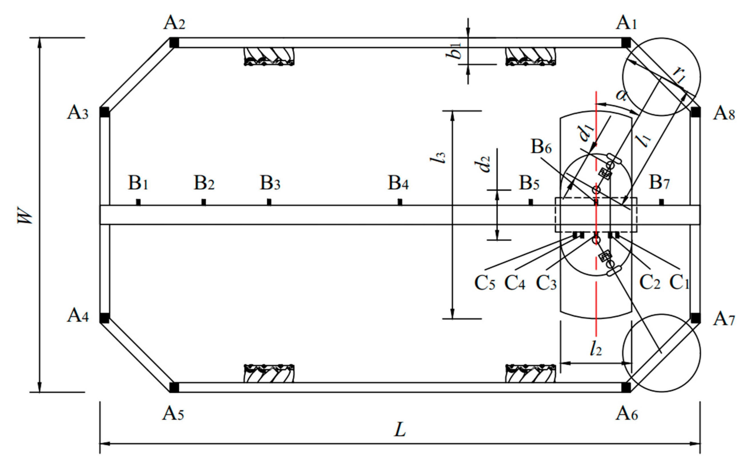
The control system includes PLC, ultrasonic sensors, and U-slot photoelectric sensors. The man–machine interface PLC, produced by Shenzhen Zhongda Youkong Technology Co., Ltd., Shenzhen, China, model MM-40MR-12MT-700-ES-E, was adopted. When the machine is located at the initial position of a dedusting room, the main sensors are fixed at the positions shown in Figure 2. Eight ultrasonic sensors are fixed at positions A1–A8 at the turning points near the four corners of the frame. These sensors are used to determine the start and the stop of the drive motors for the wheel rotation and alignment of the frame relative to the dedusting wall of the dedusting room.
The U-slot photoelectric sensors fixed on the upper slide table are used to determine the positions of the sweeper support arms at the upper slide table when the sweeper support arms retract or expand. According to the control requirements, seven sensors are set at positions B1–B7 at the upper slide table. Position B4 is located in the middle position of the upper slide table, and the other six positions are set as follows:
B 1 B 2 = B 2 B 3 = B 5 B 6 = B 6 B 7 = l 1 cos α B 3 B 4 = B 4 B 5 = 2 l 1 cos α
where l1 is the maximum total length of the horizontal projection of the sweeper support arm, m; α is the angle between the horizontal projection of the sweeper support arm and the width direction of the frame in the sweeping state, °.
The U-slot photoelectric sensors fixed on the lower slide table are used to determine the positions of the sweeper support arms when they are in the retracted or expanded state. According to the control requirements, five sensors are set at positions C1–C5 of the lower slide table. Position C3 is located in the middle of the lower slide table, and the other four positions are set as follows:
C 2 C 3 = C 3 C 4 = d 1 sin α C 1 C 2 = C 4 C 5 = d 1 sin β d 1 sin α
where d1 is the distance between the contact point of the connecting part and the sweeper support arm and the rotating shaft of the connecting part, m; β is the angle between the horizontal projection of the sweeper support arm in the retracted state and the width direction of the frame, °.
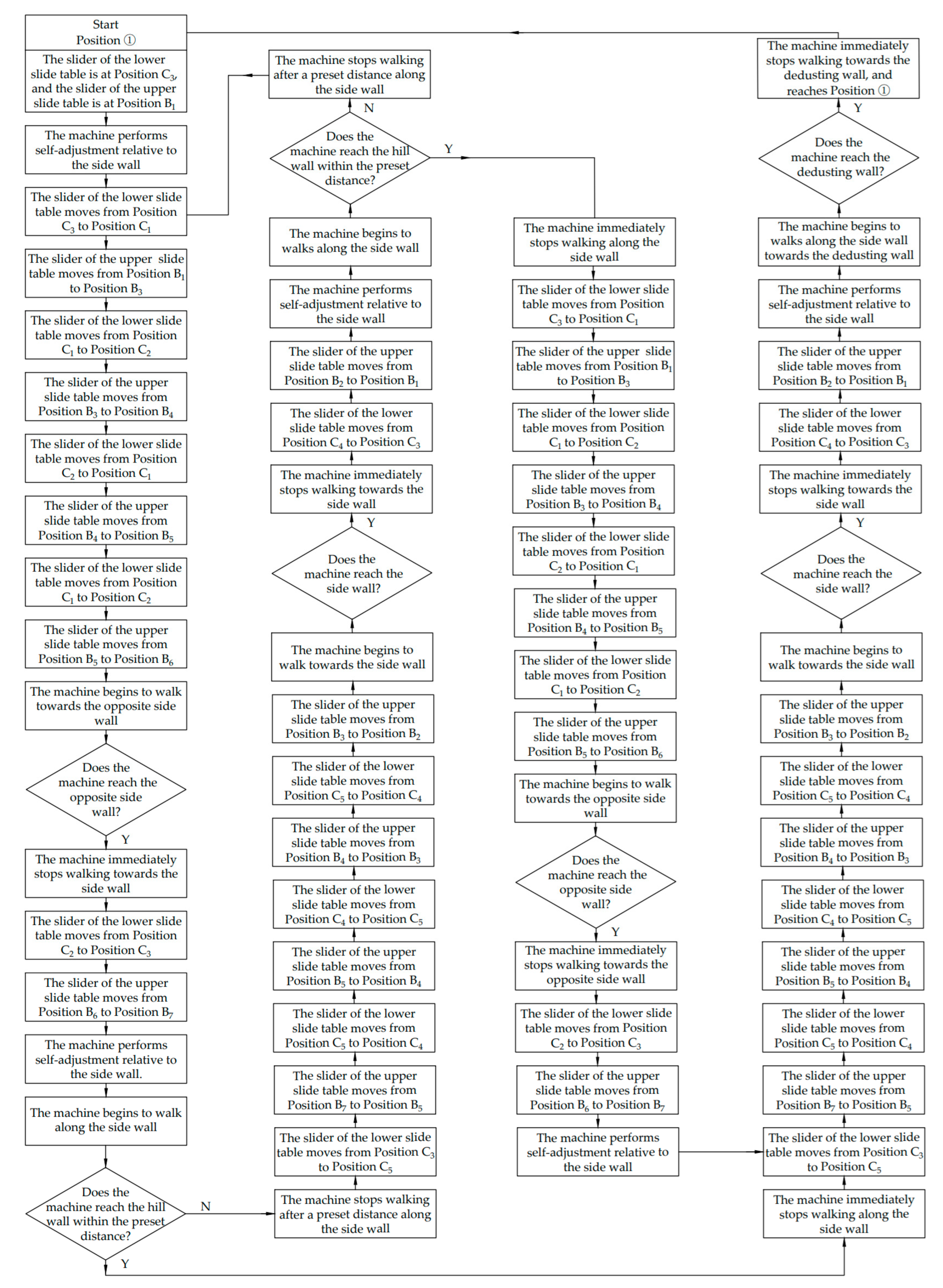
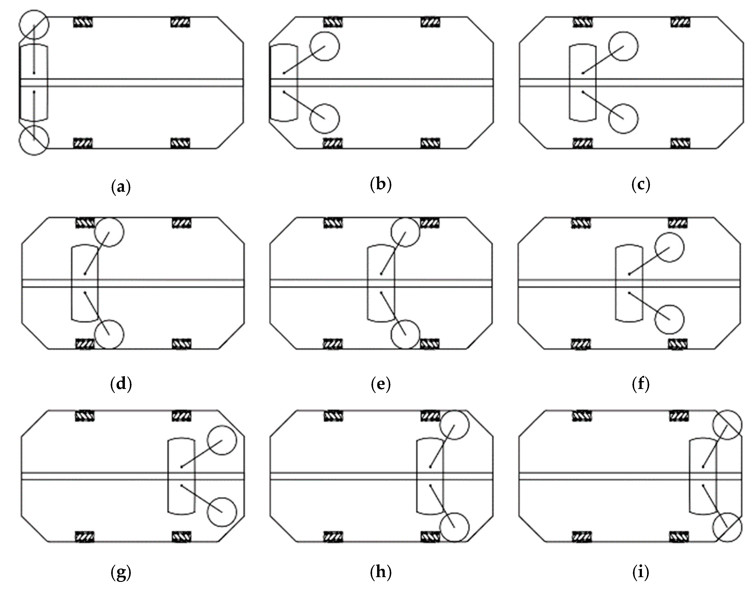
The main flow chart of the machine is shown in Figure 3, and the states of the sensors and the motors at different positions are shown in Table 3. The movement path of the machine in the dedusting room is shown in Figure 4, and the working process of the corresponding workflow of the machine is shown in Figure 5, Figure 6, Figure 7 and Figure 8. The machine repeats the same action process as follows: Position ①; Position ① → Position ②; Position ②; Position ② → Position ③; Position ③; and Position ③ → Position ④ of the preset movement path in the dedusting room. When the cleaning is completed, the machine returns to Position ①.

2.2.3. Frame and Walking Structure

The main body of the frame is welded with square steel pipes according to GB/T 3094-2012 and GB 50661-2011. Rubber wheels are installed at the four corners of the frame, and each rubber wheel exceeds the frame by 5 mm. To reduce the number of starts and stops during the reciprocating movement of the sweepers relative to the machine body, the length and width of the frame are designed as follows:
L = 8 l 1 cos α + l 2 W = 2 r 1 + 2 l 1 sin α + d 2 L 1 = 4 l 1 cos α
where L is the length of the frame, m; l2 is the width of the suction head nozzle, m; W is the width of the frame, m; r1 is the radius of the sweeper, m; d2 is the distance between the connecting pins of the sweeper support arms on both sides, m; L1 is the distance between the front and rear wheels, m.
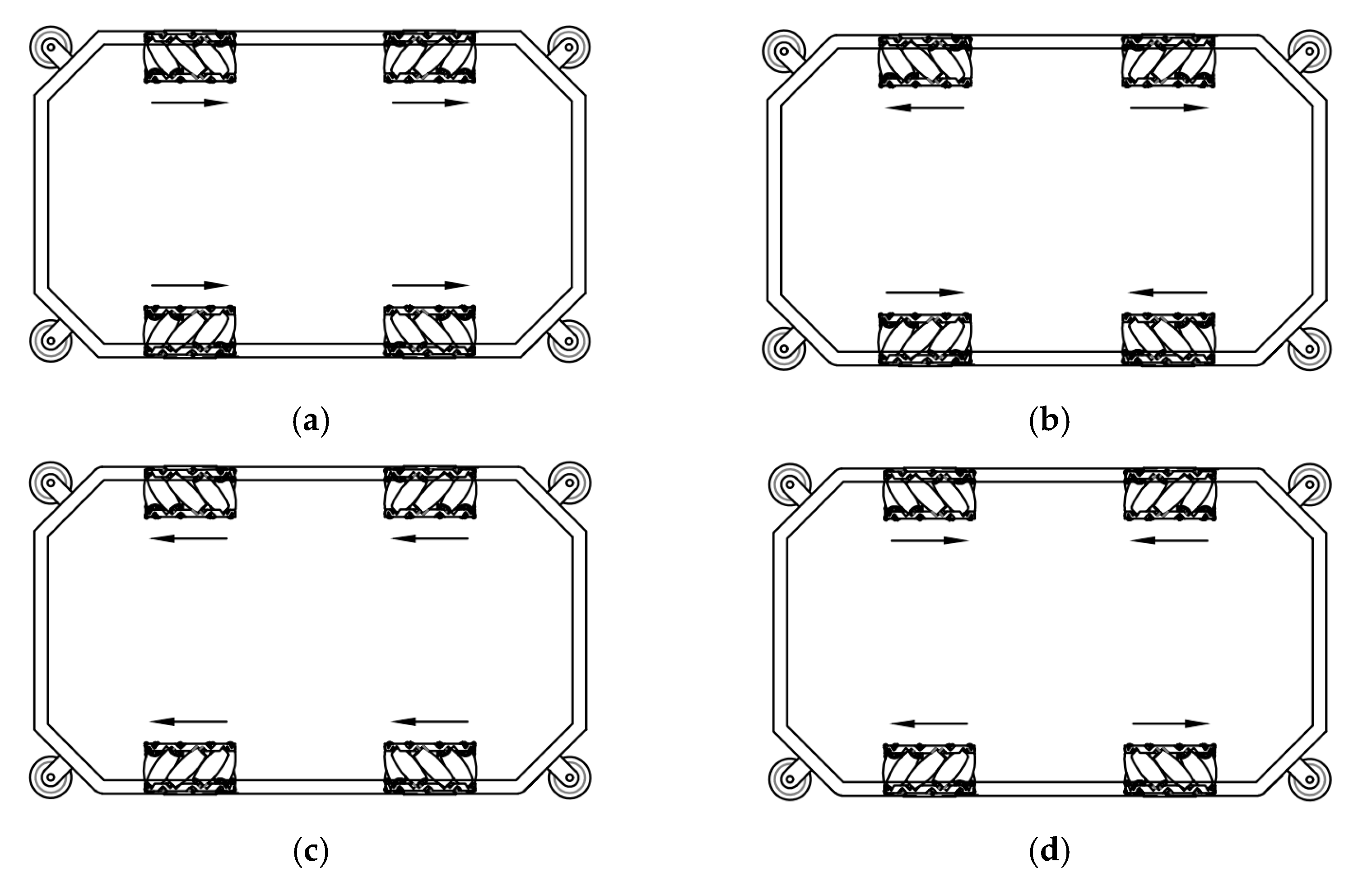
Four Mecanum wheels are driven by four stepper motors in different forward and reverse combinations to achieve horizontal and vertical forward and backward movements without turning. The outer side of the Mecanum wheels is located at the edge of the projection range of the frame plane. The Mecanum wheel combination states are shown in Figure 9, and the arrows in the figure indicate the rotation direction of the Mecanum wheels in the upward viewing direction. State 1, State 2, State 3, and State 4 are the states at Position ① → Position ②, Position ② → Position ③, Position ③ → Position ④, and, finally, return to the initial position, Position ①, as shown in Figure 3, respectively.

2.2.4. Ground Cleaning System

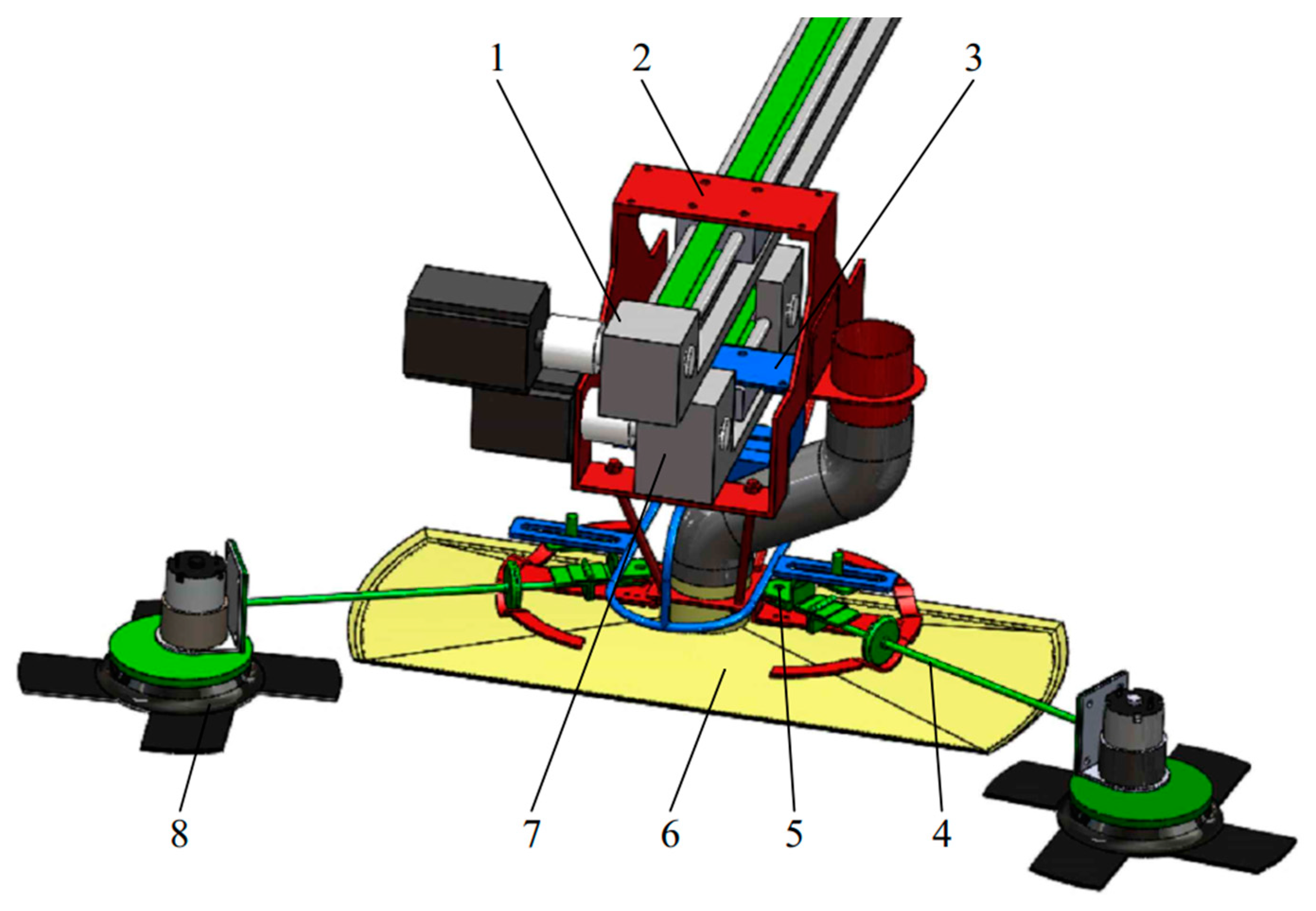
The ground cleaning system mainly comprises an upper slide table, lower slide table, support skeleton, rotary control actuator, sweeper support arm, suction head, etc., as shown in Figure 10. The upper slide table is fixed on the frame, and other parts of the ground cleaning system are fixed on the slider of the upper slide table.
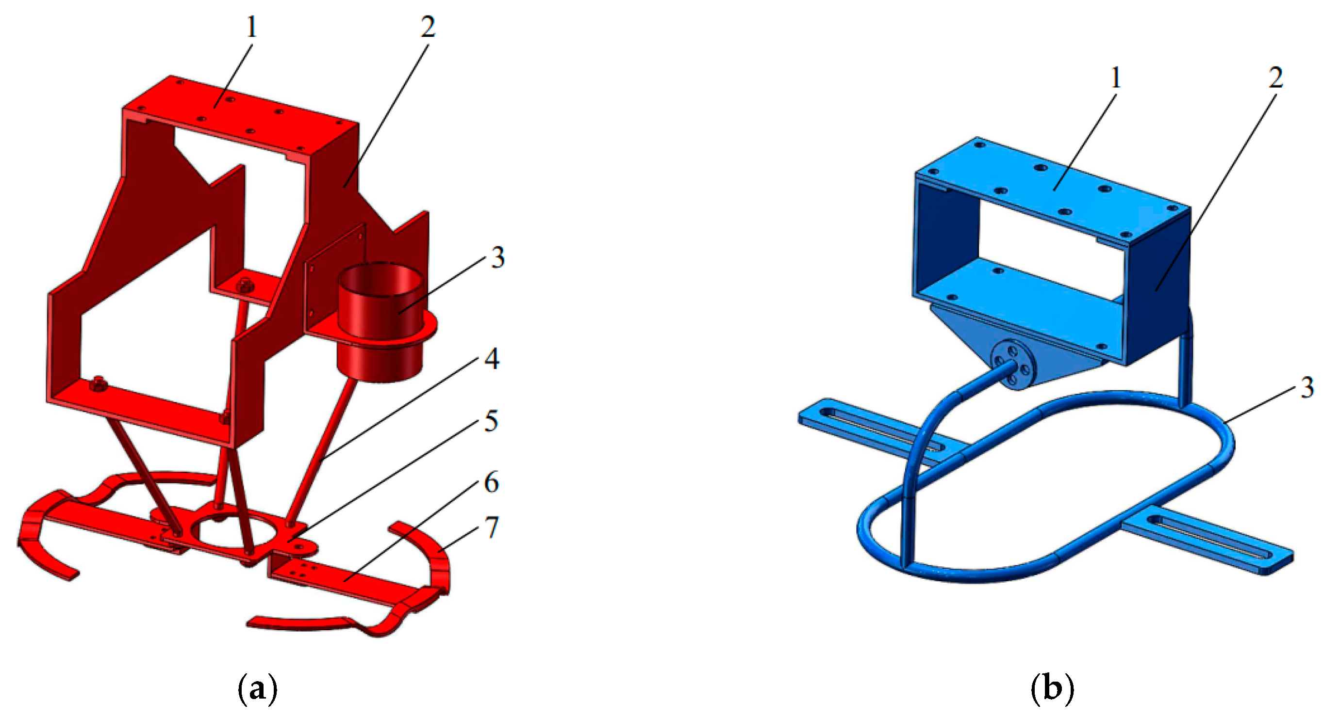
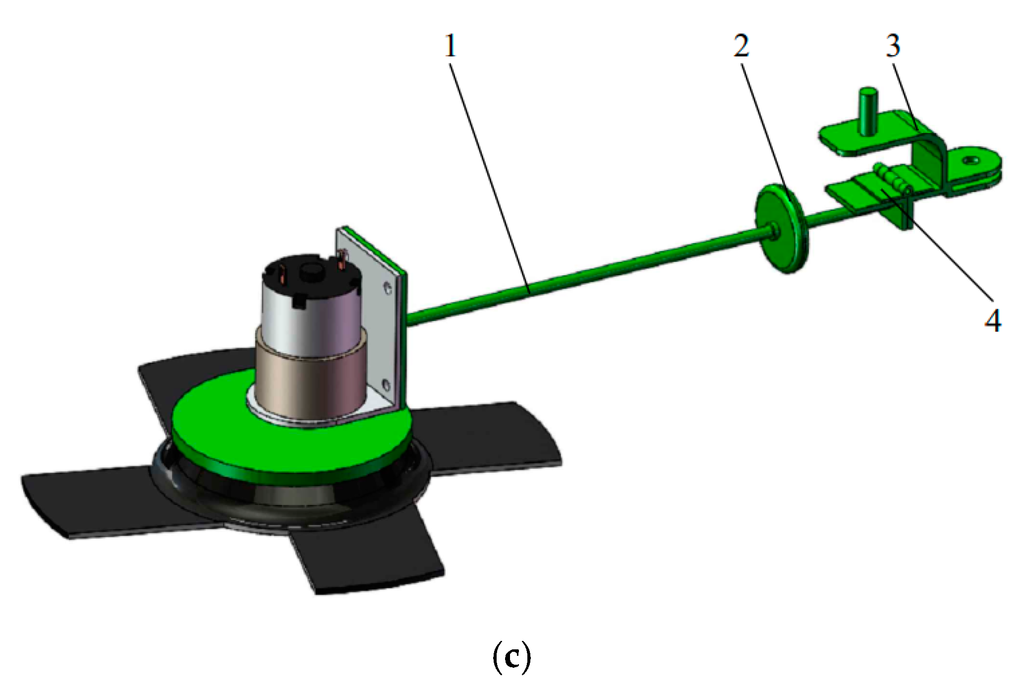
The main components of the ground cleaning system are shown in Figure 11. The upper support plate, upper support frame, fixation plate of the suction head, connecting rod of the fixation plate of the suction head, support wheel track, and support plate of the support wheel track make up the support skeleton. The rotary control actuator comprises a lower support plate, lower support frame, and rotating actuator. The sweeper support arm comprises a connecting part, support rod, hinge, and support wheel. The upper slide table moves the sweeper support arms forward and backward to make the sweepers clean dust particles and fluff under the frame. The lower slide table rotates the sweeper support arms causing the sweepers to retract or expand and change the sweeping direction.
The support skeleton fixed at the slider of the upper slide table is used to fix the lower slide table and the suction head. The rotary control actuator is fixed at the slider of the lower slide table. The groove at the rotary control actuator of the rotary control actuator contacts with the pin of the connecting part of the sweeper support arm. The lower slide table drives the rotary control actuator to move reciprocally and then drives the sweeper support arms to rotate around the connecting pin to realize the retraction or expansion of the sweeper support arms at a preset position.
The hinge connects the connecting part and the support rod. The support wheel is located at the flat or concave part of the support wheel track to make the support rod rotate around the hinge to realize the lifting and lowering of the sweepers installed at the end of the support rod. When the support wheel is located at the concave part of the support wheel track, the sweepers are in contact with the ground and are in a sweeping state. When the support wheel is located at the flat part of the support wheel track, the sweepers are not in contact with the ground and are in a nonsweeping state. According to the reliability requirements of the retracting process, β should meet the following criterion:
arccos l 1 sin α b 1 l 1 β < π 2
where b1 is the thickness of Mecanum wheels, m.
The main body of the sweepers can be 30 mm beyond the projection range of the frame when the sweepers are in a sweeping state. To prevent the interference of the sweepers, Mecanum wheels, and the suction head and to ensure the compact structure and that there is no blind area under the frame for sweeping, the following dimensional relationship must be met:
( l 3 d 2 ) 2 + l 2 2 + 2 r 1 2 l 1 r 1 ( 1 cos γ ) b 1 cos γ sin α
where l3 is the length of the suction head nozzle, m; γ is the angle between the sweeper support arm and the width direction of the frame when the edge of the sweeper is closest to the Mecanum wheel, °.

2.2.5. Dedusting System

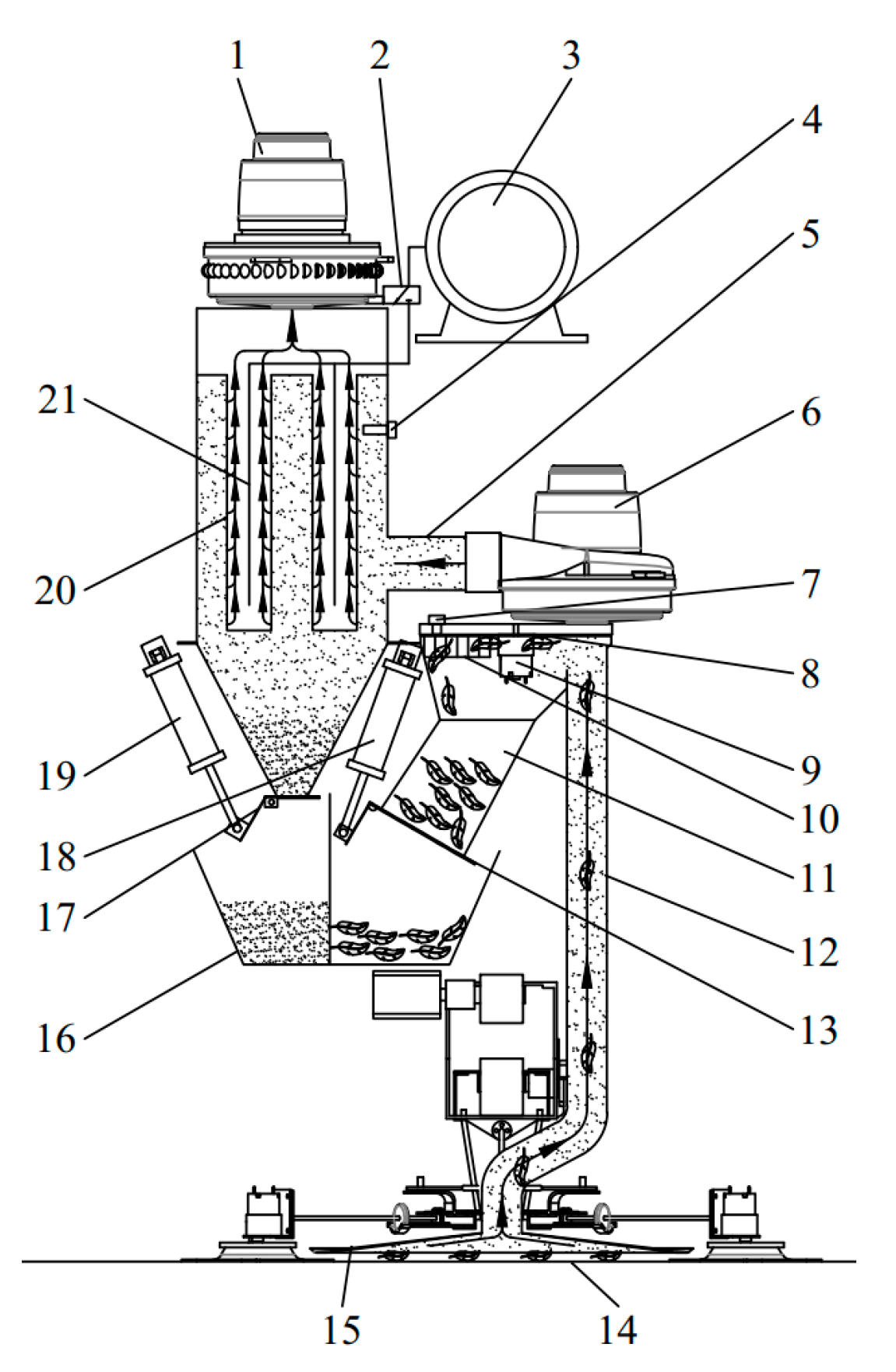
The working principle of the dedusting system is shown in Figure 12. The system mainly includes a fluff separation assembly, dust particle separation assembly, dust particle and fluff storage box, etc. The core component of the fluff separation assembly is the fluff separator, as shown in Figure 13, which consists of separator housing, fluff-separating disc, temporary storage, etc. The fluff-separating disc rotates continuously under its drive motor, gas mixtures pass through the fluff-separating disc under the front vacuum cleaner, and fluff in the gas mixtures stays on the surface of the fluff-separating disc. Until the fluff is driven to the area without negative pressure, it drops to the temporary storage under the fluff-cleaning comb, and other gas mixtures continue flowing to the dedusting box. The core component of the dust particle separation assembly is the dedusting box. After other gas mixtures enter the dedusting box, the air passes through the filter bag, and the dust particles are retained in the lower part of the filter bag under the rear vacuum cleaner. Then, they gradually deposit at the bottom of the dedusting box. The quality of the gas treatment is related to the filter bag, and some devices for further gas treatment can also be added to the upper part of the dedusting box. The local negative pressure might be too large when the fluff filter disc is blocked by fluff in the fluff separator, and the filter bag is blocked by dust particles in the dedusting box. The pulse bag cleaner can remove the dust particles on the surface of the filter bag, and self-cleaning adjustments can be made using the fluff-cleaning comb after the vacuum cleaner is stopped. The electromotive handspike for fluff discharge drives the fluff discharge port cover to realize the opening and closing of the fluff separator, and the electromotive handspike for dust particle discharge drives the dust particle discharge port cover to realize the opening and closing of the dedusting box.
The filter bag specifications comply with GB/T 6719-2009. The air volume processed by the dedusting system is calculated as follows:
Q = 60 n 1 π D h v 1
where Q is the air volume processed by the dedusting system, m3/h; n1 is the number of filter bags; D is the diameter of the filter bags, m; h is the height of the filter bags, m; v1 is the filtering speed of the filter bag, m/s.
The wind speed of the front vacuum cleaner is calculated as follows:
v 2 = Q 3600 S
where v2 is the wind speed of the front vacuum cleaner, m/s; S is the cross-sectional area of the air inlet of the front vacuum cleaner, m2.
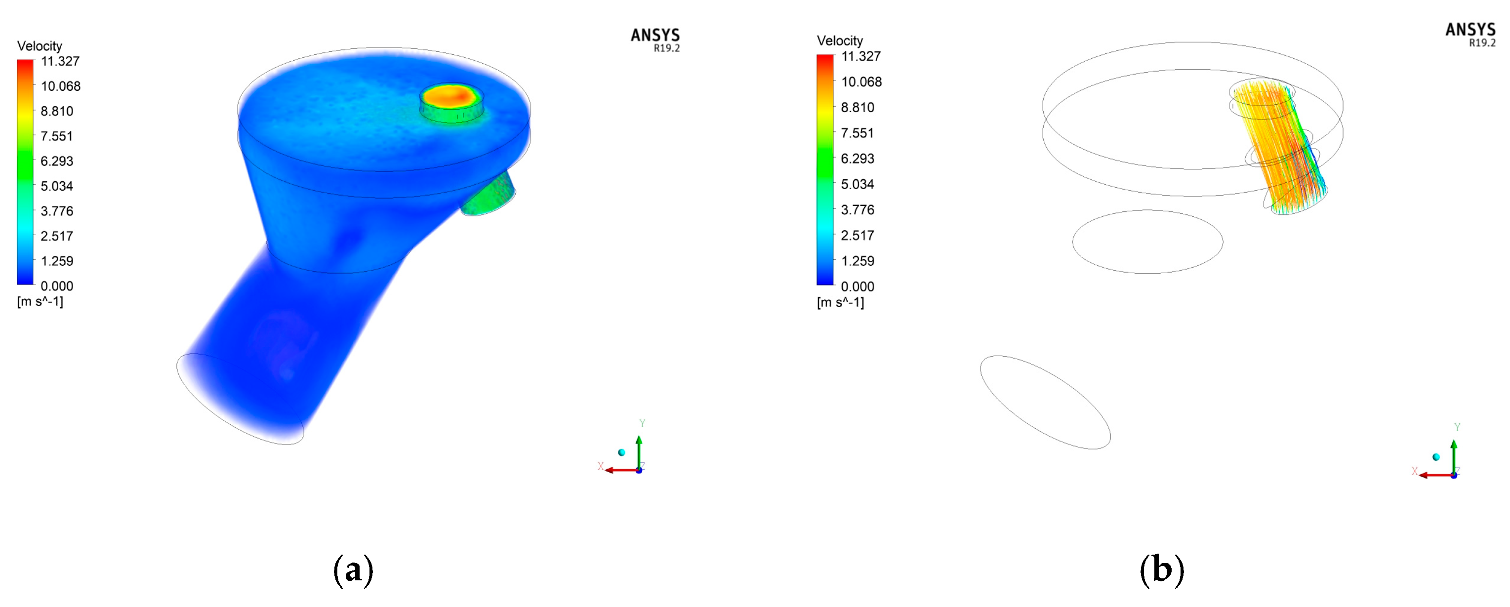
Using wind speeds for the front vacuum cleaner of 10 m/s, 15 m/s, 20 m/s, and 25 m/s, the airflow velocity distribution and dust particle track in the fluff separator under stable working conditions were simulated using Ansys Fluent 19.2 software, as shown in Figure 14. The airflow velocity distribution and dust particle track in the fluff separator under the 4 wind speeds were basically the same, and the airflow was stable. The airflow velocity in the temporary storage of the fluff separator was almost 0 m/s, which is suitable for the temporary storage of fluff. The dust particle track is between the inlet and outlet of the airflow of the fluff separator, and the dust particles can pass through smoothly. The overall structure of the fluff separator fully meets the requirements for the separation and temporary storage of fluff, enabling the smooth passage of dust particles.

2.3. Experimental Conditions

To accurately measure the influence of the machine on the experimental indexes under different experimental factors, the experiments were carried out in a simulated dedusting room. The parameter optimization experiments were conducted on 10–17 February 2023. The experimental site was Huancui District, Weihai, Shandong, China. The fluctuation range of the temperature and relative humidity during the tests were 4–10 °C and 42–51% in the simulated dedusting room, respectively. The area of the simulated dedusting room was 5 m long and 3.6 m wide, with a flat floor.

2.4. Experimental Materials

The experimental materials were 500 pieces of fluff and 7 kg dust particles taken from the inner surface of a chicken house. Four hundred pieces of fluff were selected for the experiment, with an average length of 92.3 mm and an average width of 36.2 mm. The average weight of a single piece of fluff was 0.0493 g. The bulk density of the dust particles was 0.62 g/cm3. The experimental equipment and tools included an electronic temperature hygrometer, laser tachometer, voltage regulator, electronic balance, vernier caliper, 500 mL measuring cylinder, meter ruler, broom, and dustpan.

2.5. Experimental Design

2.5.1. Experimental Factors and Experimental Indexes

Considering the working process of the machine, the movement speed, rotation speed of the sweeper, and distance between the suction head nozzle and ground were selected as the experimental factors. The experimental indexes were the dust particle removal rate and the fluff removal rate. The dust particle removal rate is calculated using the following formula:
M j = 1 k i = 1 k m m i j m × 100 %
where Mj is the average dust particle removal rate of all k repeated tests in the experimental scheme j, %; m is the mass of the dust particles deposited in the cleaning area before each test, g; m’ij is the mass of the dust particles that are not cleaned up in the cleaning area of the machine in the ith test in the experimental scheme j, g.
The fluff removal rate is calculated with the following formula:
N j = 1 k i = 1 k n n i j n × 100 %
where Nj is the average fluff removal rate of all k repeated tests in the experimental scheme j, %; n is the number of pieces of fluff placed in the cleaning area before each test; n’ij is the number of pieces of fluff that are not cleaned up in the cleaning area of the machine in the ith test in the experimental scheme j.

2.5.2. Experimental Scheme

The experiment was carried out with a three-factor quadratic general rotation combination design. The code table of the experimental factors was determined according to the parameter range of the experimental factors in normal operation, as shown in Table 4. The experimental scheme is shown in Table 5.

2.5.3. Experimental Methods

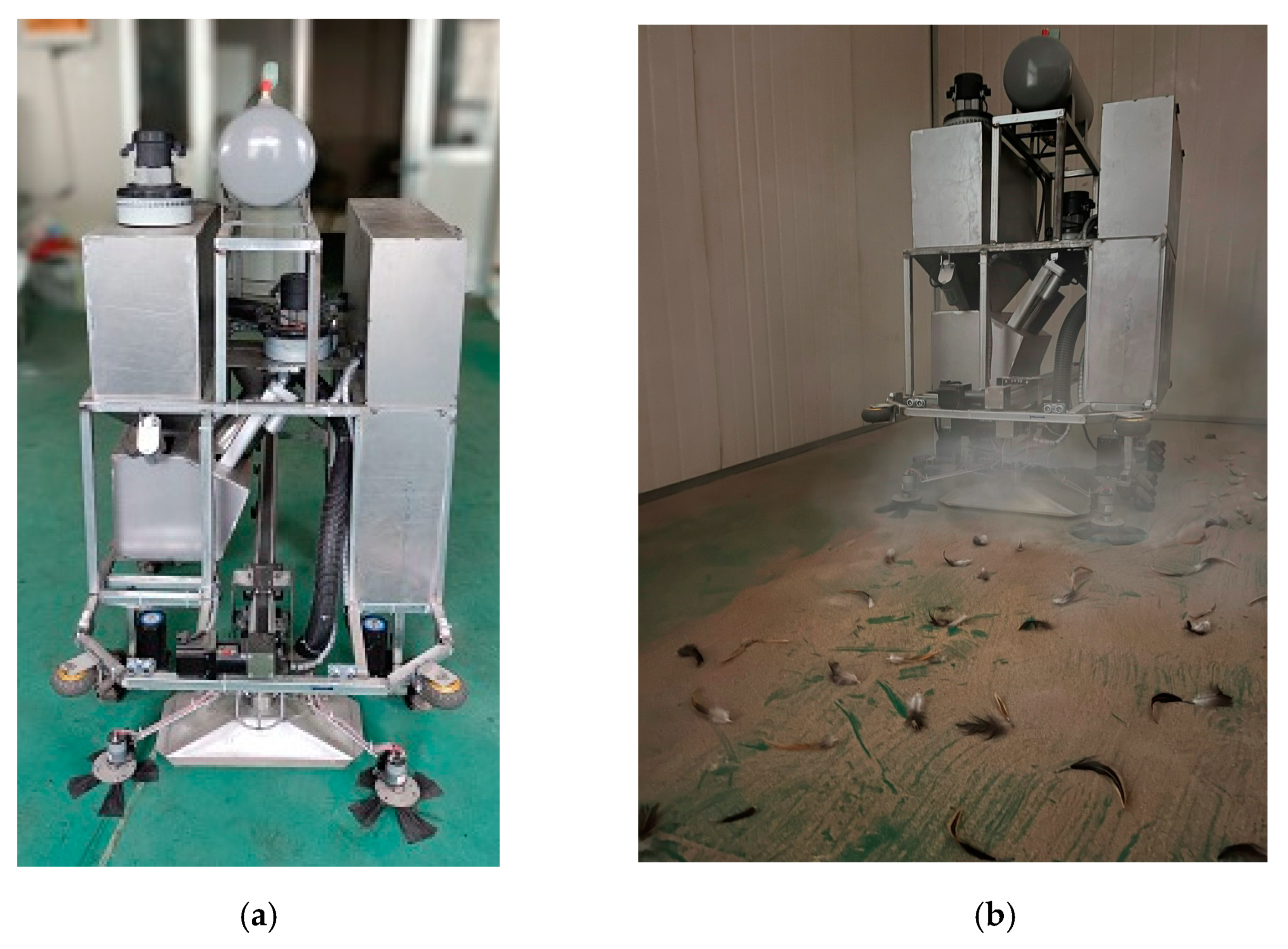
According to the experimental scheme and in reference to GB/T 38048.2-2021, the dust particles were evenly spread on the ground at a surface concentration of 150 g/m2, and the fluff was evenly placed on the ground at a surface concentration of 10 pieces/m2. The machine moved along the long side of the simulated dedusting room at a preset speed, and 3 round trips were designed to completely clean the area. After, the uncleaned dust particles and fluff were collected, the number of pieces of the latter was counted, and the mass of the latter was determined; the fluff removal rate and dust particle removal rate were calculated. The test was repeated 3 times for each experimental scheme. The experimental prototype is shown in Figure 15.

3. Results and Analysis

The experimental results are shown in Table 5. The influence of three factors on the dust particle removal rate and the fluff removal rate were analyzed using Design-Expert 12 software. The variance analysis is shown in Table 6. The regression model of the influence of the three experimental factors on the dust particle removal rate is very significant (p < 0.01); the lack of fit is not significant (p > 0.05), indicating that the obtained regression equation is extremely significant. The R2 of the fitted quadratic regression equation is 0.9641, indicating a good fit. Coefficients A, B, and C are highly significant (p < 0.01); coefficients A2, B2, and C2 are significant (p < 0.05); and coefficients AB, AC, and BC are not significant (p > 0.05). The regression model equation is given as follows:
Y 1 = 19.47 + 55.44 A + 0.56 B + 2.21 C 319.44 A 2 1.3 × 10 3 B 2 0.13 C 2
The optimal parameter combination and corresponding predicted maximum dust particle removal rate are given as follows:
Y1max = Y1(A,B,C) = Y1(0.1,216,10) = 91.7%
The regression model of the influence of the three experimental factors on the fluff removal rate is very significant (p < 0.01); the lack of fit is not significant (p > 0.05), indicating that the obtained regression equation is extremely significant. The R2 of the fitted quadratic regression equation is 0.9404, indicating a good fit. Coefficients A and C are highly significant (p < 0.01); coefficients B, AC, A2, B2, and C2 are significant (p < 0.05); and coefficients AB and BC are not significant (p > 0.05). The regression model equation is given as follows:
Y 2 = 12.56 + 157.42 A + 0.45 B + 4.13 C 6.56 A C 325.63 A 2 1.24 × 10 3 B 2 0.11 C 2
The optimal parameter combination and corresponding predicted maximum fluff removal rate are given as follows:
Y2max = Y2(A,B,C) = Y2(0.1,180,16) = 93.5%
Since the optimal parameter combinations of the three experimental factors corresponding to the maximum dust particle removal rate and maximum fluff removal rate obtained from the two regression equations are different, it was necessary to use Design-Expert 12 software to further optimize the parameters. It was obtained that the dust particle removal rate and fluff removal rate reach maximal values simultaneously at the same weight. The parameter optimization conditions are given as follows:
max Y = max ( Y 1 ( A , B , C ) + Y 2 ( A , B , C ) ) s . t . 0.1 A 0.3 150 B 240   10 C 20
The optimized parameter combination is as follows: movement speed of 0.1 m/s, rotation speed of the sweeper of 198 r/min, and distance between the suction head nozzle and ground of 12 mm. The corresponding predicted dust particle removal rate and fluff removal rate are 90.4% and 91.2%, respectively.

4. Performance Experiment

The performance experiment was conducted on 26 February 2023 with the same experimental conditions and experimental materials as the parameter optimization experiment. According to the results of the parameter optimization experiment, the parameters corresponding to the three experimental factors in the performance experiment were the movement speed of 0.1 m/s, rotation speed of the sweeper of 198 r/min, and distance between the suction head nozzle and ground of 12 mm. The performance experiment was performed five times in total, and the experimental measurement and calculation methods were the same as for the parameter optimization experiment. The experimental results are shown in Table 7, indicating that the dust particle removal rate was 90.7%, and the fluff removal rate was 91.7%. The designed and constructed machine performs well and can meet actual needs.

5. Conclusions

We designed an automatic ground cleaning machine for dedusting rooms of chicken houses. The machine mainly comprised a power system, control system, frame and walking structure, ground cleaning system, and dedusting system. The working principle and structural composition of the machine and the technical parameters of each key structure were analyzed. The control system was designed to accurately control the working states of the power system through reliable sensor signals according to the working technical requirements. The ground cleaning system was designed to realize the maximum extent of unobstructed back-and-forth movements, lifting and lowering the sweeper, and retracting and expanding the sweeper support arm under the frame. The walking structure was designed to realize horizontal and vertical forward and backward movements without turning. The dedusting system could realize step-by-step cleaning, and dust particles and fluff were separated independently. The ground cleaning machine consumes 3.1 kW for one hour.
We performed parameter optimization experiments and performance experiments. The parameter optimization experiments were carried out using a quadratic general rotary combination design with the movement speed, rotation speed of the sweeper, and distance between the suction head nozzle and ground as the experimental factors, and the regression equations of the dust particle removal rate and fluff removal rate were obtained using Design-Expert 12 software. The two regression equations reflected well the parametric influence of the three experimental factors on the experimental indexes. The parameters of the two regression equations were further optimized, and the optimized parameter combination was a movement speed of 0.1 m/s, rotation speed of the sweeper of 198 r/min, and distance between the suction head nozzle and the ground of 12 mm. The corresponding predicted dust particle removal rate and fluff removal rate were 90.4% and 91.2%, respectively. According to the performance experiment, the dust particle removal rate was 90.7% and the fluff removal rate was 91.7% under the optimized parameter combination. It was demonstrated that the machine worked well and stably, meeting the daily cleaning needs of large-, medium-, and small-scale rectangular dedusting rooms. In the future, we will continue to improve the ground cleaning machine by focusing on precise positioning, improving adaptability, enhancing intelligence, and improving safety monitoring.

Author Contributions

Conceptualization, Y.Y. and S.L.; methodology, Y.Y.; software, Y.Y. and S.L.; validation, Y.Y., A.D., Z.L. and Q.W.; formal analysis, Y.Y., A.D. and Z.L.; investigation, Z.L. and Q.W.; resources, S.L.; data curation, Y.Y.; writing—original draft preparation, Y.Y., A.D., Z.L. and Q.W.; writing—review and editing, Y.Y.; visualization, Y.Y.; supervision, S.L.; project administration, Y.Y. and S.L. All authors have read and agreed to the published version of the manuscript.

Funding

This research received no external funding.

Institutional Review Board Statement

Not applicable.

Data Availability Statement

The data presented in this study are available upon request from the authors.

Acknowledgments

The authors appreciate the support provided by Huancui District Chengsheng Machinery Processing Factory in terms of the mechanical processing.

Conflicts of Interest

The authors declare no conflict of interest.

Nomenclature

l1The maximum total length of the horizontal projection of the sweeper support arm, m
d1The distance between the contact point of the connecting part and the sweeper support arm and the rotating shaft of the connecting part, m
LThe length of the frame, m; l2 is the width of the suction head nozzle, m
r1The radius of the sweeper, m; d2 is the distance between the connecting pins of the sweeper support arms on both sides, m
WThe width of the frame, m
L1The distance between the front and rear wheels, m
b1The thickness of Mecanum wheels, m
l3The length of the suction head nozzle, m
QAir volume processed by the dedusting system, m3/h
n1Number of filter bags
DDiameter of filter bags, m; h is height of filter bags, m
v1Filtering wind speed of of filter bag, m/s
v2Wind speed of the front vacuum cleaner, m/s
SCross-sectional area of the air inlet of the front vacuum cleaner, m2
MjThe average dust particle removal rate of all k repeated tests in the experimental scheme j, %
mThe mass of the dust particles deposited in the cleaning area before each test, g
m’ijThe mass of the dust particles that are not cleaned up in the cleaning area of the machine in the ith test in the experimental scheme j, g
NjThe average fluff removal rate of all k repeated tests in the experimental scheme j, %
nThe number of pieces of fluff placed in the cleaning area before each test
n’ijThe number of pieces of fluff that are not cleaned up in the cleaning area of the machine in the ith test in the experimental scheme j
αThe angle between the horizontal projection of the sweeper support arm and the width direction of the frame in the sweeping state, °
βThe angle between the horizontal projection of the sweeper support arm in the retracted state and the width direction of the frame, °
γThe angle between the sweeper support arm and the width direction of the frame when the edge of the sweeper is closest to the Mecanum wheel, °

References

  1. Yang, W.; Guo, M.; Liu, G.; Yu, G.; Wang, P.; Wang, H.; Chai, T. Detection and analysis of fine particulate matter and microbial aerosol in chicken houses in Shandong Province, China. Poult. Sci. 2018, 97, 995–1005. [Google Scholar] [CrossRef] [PubMed]
  2. Browne, W.J.; Caplen, G.; Edgar, J.; Wilson, L.R.; Nicol, C.J. Consistency, transitivity and inter-relationships between measures of choice in environmental preference tests with chickens. Behav. Process 2010, 83, 72–78. [Google Scholar] [CrossRef] [PubMed]
  3. Hu, Q.; Dong, H.M.; Tao, X.P.; Chang, J.; Zhang, J.Z.; Sun, H. Technologies for reducing dust and bacteria in exhaust-air from poultry and livestock farms. Chin. J. Agrometeorol. 2000, 21, 18–22. [Google Scholar]
  4. Chai, T.J.; Zhao, Y.L.; Liu, H.; Liu, W.B.; Huang, Y.Y.; Yin, M.Y.; Li, X.H. Studies on the concentration and aerodynamic diameters of microbiological aerosol in the poultry house. China Poult. 2001, 37, 9–11. [Google Scholar]
  5. Olejnik, K.; Popiela, E.; Opaliński, S. Emerging Precision Management Methods in Poultry Sector. Agriculture 2022, 12, 718. [Google Scholar] [CrossRef]
  6. Gao, M.; Jia, R.Z.; Qiu, T.L.; Song, Y.; Wang, X.M. Progress in research on characteristics of bioaerosol diffused during livestock breeding. J. Ecol. Rural. Environ. 2015, 31, 12–21. [Google Scholar]
  7. Wang, K.Y.; Dai, S.Y.; Wang, L.J. Research progress on pollution and monitoring technology of particulate matter from livestock and poultry farms. Trans. Chin. Soc. Agric. Mach. 2017, 48, 232–241. [Google Scholar]
  8. Cambra-López, M.; Torres, A.G.; Aarnink, A.J.A.; Ogink, N.W.M. Source analysis of fine and coarse particulate matter from livestock houses. Atmos. Environ. 2011, 45, 694–707. [Google Scholar] [CrossRef] [Green Version]
  9. Dukhta, G.; Halas, V. Dynamic, Mechanistic Modeling Approach as a Tool to Mitigate N Excretion in Broilers. Agriculture 2023, 13, 808. [Google Scholar] [CrossRef]
  10. Mitloehner, F.M.; Calvo, M.S. Worker health and safety in concentrated animal feeding operations. J. Agric. Saf. Health 2008, 14, 163–187. [Google Scholar] [CrossRef]
  11. Cambra-López, M.; Aarnink, A.J.A.; Zhao, Y.; Calvet, S.; Torres, A.G. Airborne particulate matter from livestock production systems: A review of an air pollution problem. Environ. Pollut. 2010, 158, 1–17. [Google Scholar] [CrossRef] [PubMed]
  12. Winkel, A.; Mosquera, J.; Koerkamp, P.W.G.G.; Ogink, N.W.M.; Aarnink, A.J.A. Emissions of particulate matter from animal houses in the Netherlands. Atmos. Environ. 2015, 111, 202–212. [Google Scholar] [CrossRef]
  13. Dong, H.M.; He, Q.; Tao, X.P.; Chang, J.; Zhang, J.Z.; Sun, H.; Zhang, B.H. Design and field experiment of biomass dust-break wall. Trans. Chin. Soc. Agric. Eng. 2000, 16, 94–98. [Google Scholar]
  14. Sun, H.Z.; Xi, J.Z.; Tong, Y.G.; Zeng, D.; Chen, H. Evaluation of application effect of dust removal room in chicken house with microbial aerosol. China Poult. 2020, 42, 62–66. [Google Scholar]
  15. Zhong, Z.B.; Wang, N. The size distribution and health risk assessment of microbe bacterial aerosol in livestock and poultry house. China Anim. Health Insp. 2014, 31, 101–105. [Google Scholar]
  16. Zhao, Y.; Aarnink, A.J.A.; Jong, M.C.M.D.; Koerkamp, P.W.G.G. Airborne microorganisms from livestock production systems and their relation to dust. Crit. Rev. Environ. Sci. Technol. 2014, 44, 1071–1128. [Google Scholar] [CrossRef]
  17. Kim, K.H.; Kabir, E.; Kabir, S. A review on the human health impact of airborne particulate matter. Environ. Int. 2015, 74, 136–143. [Google Scholar] [CrossRef]
  18. Hadlocon, L.S.; Zhao, L.Y.; Bohrer, G.; Kenny, W.; Garrity, S.R.; Wang, J.; Wyslouzil, B.; Upadhyay, J. Modeling of particulate matter dispersion from a poultry facility using AERMOD. J. Air Waste Manag. Assoc. 2015, 65, 206–217. [Google Scholar] [CrossRef]
  19. Holmes, N.S.; Morawska, L. A review of dispersion modelling and its application to the dispersion of particles: An overview of different dispersion models available. Atmos. Environ. 2006, 40, 5902–5928. [Google Scholar] [CrossRef] [Green Version]
  20. Gerald, C.; Mcpherson, C.; Mcdaniel, T.; Xu, Z.G.; Holmes, B.; Williams, L.; Whitley, N.; Waterman, J.T. A biophysiochemical analysis of settled livestock and poultry housing dusts. Am. J. Agric. Biol. Sci. 2014, 9, 153–166. [Google Scholar] [CrossRef] [Green Version]
  21. Le Bouquin, S.; Huneau-Salaun, A.; Huonnic, D.; Balaine, L.; Martin, S.; Michel, V. Aerial dust concentration in cage-housed, floor-housed, and aviary facilities for laying hens. Poult. Sci. 2013, 92, 2827–2833. [Google Scholar] [CrossRef] [PubMed]
  22. Hayes, M.; Xin, H.W.; Li, H.; Shepherd, T.; Zhao, Y.; Stinn, J. Ammonia, Greenhouse Gas, and Particulate Matter Emissions of Aviary Layer Houses in the Midwestern U.S. Trans. ASABE 2013, 56, 1921–1932. [Google Scholar]
  23. Lin, X.J.; Cortus, E.L.; Zhang, R.; Heber, S.; Heber, A.J. Air emissions from broiler houses in California. Trans. ASABE 2012, 55, 1895–1908. [Google Scholar] [CrossRef]
  24. Roumeliotis, T.S.; Dixon, B.J.; Heyst, B.J.V. Characterization of gaseous pollutant and particulate matter emission rates from a commercial broiler operation part II: Correlated emission rates. Atmos. Environ. 2010, 44, 3778–3786. [Google Scholar] [CrossRef]
  25. Zou, X.G.; Wang, S.Y.; Qian, Y.; Gong, F.; Zhang, S.X.; Hu, J.X.; Liu, W.C.; Song, Y.Y.; Zhang, S.K.; Meng, J.W.; et al. Study of Ammonia Concentration Characteristics and Optimization in Broiler Chamber during Winter Based on Computational Fluid Dynamics. Agriculture 2022, 12, 182. [Google Scholar] [CrossRef]
  26. Mostafa, E.; Buescher, W. Indoor air quality improvement from particle matters for laying hen poultry houses. Biosyst. Eng. 2011, 109, 22–36. [Google Scholar] [CrossRef]
  27. Li, Z.G.; Zheng, W.C.; Wei, Y.X.; Li, B.M.; Wang, Y.; Zheng, H.Y. Prevention of particulate matter and airborne culturable bacteria transmission between double-tunnel ventilation layer hen houses. Poult. Sci. 2019, 98, 2392–2398. [Google Scholar] [CrossRef]
  28. Gonçalves, J.C.; Lopes, A.M.G.; Pereira, J.L.S. Computational Fluid Dynamics Modeling of Ammonia Concentration in a Commercial Broiler Building. Agriculture 2023, 13, 1101. [Google Scholar] [CrossRef]
  29. Komlósi, I. Recent Advancements in Poultry Health, Nutrition and Sustainability. Agriculture 2022, 12, 516. [Google Scholar] [CrossRef]
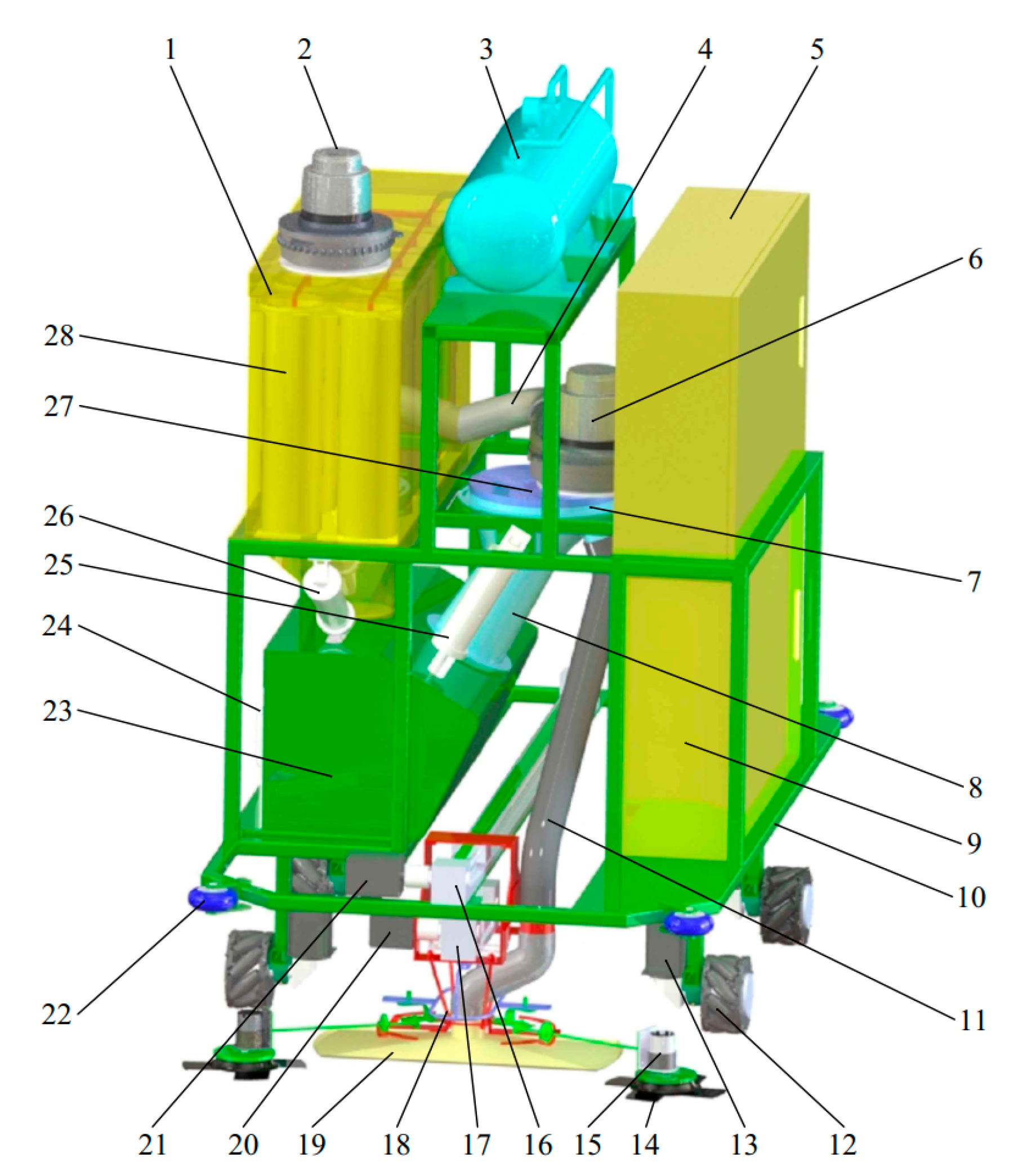
Figure 1. Overall structure: (1) dedusting box; (2) rear vacuum cleaner; (3) air pressure tank; (4) rear conveying pipe; (5) control box; (6) front vacuum cleaner; (7) fluff separator; (8) temporary storage of the fluff separator; (9) battery pack box; (10) frame; (11) front conveying pipe; (12) Mecanum wheel; (13) drive motor for the wheel rotation; (14) sweeper; (15) drive motor for the sweeper rotation; (16) upper slide table; (17) lower slide table; (18) ground cleaning system; (19) suction head; (20) drive motor of the lower slide table; (21) drive motor of the upper slide table; (22) rubber wheel; (23) dust particle and fluff storage box; (24) dust particle and fluff storage hopper; (25) electromotive handspike for fluff discharge; (26) electromotive handspike for dust particle discharge; (27) drive motor for the fluff-separating disc rotation; (28) filter bag in the dedusting box.
Agriculture 13 01231 g001
Figure 2. Fixation positions of the main sensors.
Agriculture 13 01231 g002
Figure 3. Flow chart.
Agriculture 13 01231 g003
Figure 4. Movement path of the machine in the dedusting room: (1) dedusting wall; (2) dedusting room; (3) side wall; (4) hill wall; (5) chicken house; (6) exhaust fan in chicken house.
Agriculture 13 01231 g004
Figure 5. Action process of the ground cleaning system at Position ① in the dedusting room: (a) slider of the upper slide table at position B1 and the slider of the lower slide table at position C3; (b) slider of the upper slide table at position B1 and the slider of the lower slide table at position C1; (c) slider of the upper slide table at position B3 and the slider of the lower slide table at position C1; (d) slider of the upper slide table at position B3 and the slider of the lower slide table at position C2; (e) slider of the upper slide table at position B4 and the slider of the lower slide table at position C2; (f) slider of the upper slide table at position B4 and the slider of the lower slide table at position C1; (g) slider of the upper slide table at position B5 and the slider of the lower slide table at position C1; (h) slider of the upper slide table at position B5 and the slider of the lower slide table at position C2; (i) slider of the upper slide table at position B6 and the slider of the lower slide table at position C2.
Agriculture 13 01231 g005
Figure 6. Action process of the ground cleaning system at Position ② in the dedusting room: (a) slider of the upper slide table at position B6 and the slider of the lower slide table at position C2; (b) slider of the upper slide table at position B6 and the slider of the lower slide table at position C3; (c) slider of the upper slide table at position B7 and the slider of the lower slide table at position C3.
Agriculture 13 01231 g006
Figure 7. Action process of the ground cleaning system at Position ③ in the dedusting room: (a) slider of the upper slide table at position B7 and the slider of the lower slide table at position C3; (b) slider of the upper slide table at position B7 and the slider of the lower slide table at position C5; (c) slider of the upper slide table at position B5 and the slider of the lower slide table at position C5; (d) slider of the upper slide table at position B5 and the slider of the lower slide table at position C4; (e) slider of the upper slide table at position B4 and the slider of the lower slide table at position C4; (f) slider of the upper slide table at position B4 and the slider of the lower slide table at position C5; (g) slider of the upper slide table at position B3 and the slider of the lower slide table at position C5; (h) slider of the upper slide table at position B3 and the slider of the lower slide table at position C4; (i) slider of the upper slide table at position B2 and the slider of the lower slide table at position C4.
Agriculture 13 01231 g007
Figure 8. Action process of the ground cleaning system at Position ④ in the dedusting room: (a) slider of the upper slide table at position B2 and the slider of the lower slide table at position C4; (b) slider of the upper slide table at position B2 and the slider of the lower slide table at position C3; (c) slider of the upper slide table at position B1 and the slider of the lower slide table at position C3.
Agriculture 13 01231 g008
Figure 9. Mecanum wheel combination states (The arrow represents the rotation direction of the corresponding Mecanum wheel): (a) State 1; (b) State 2; (c) State 3; (d) State 4.
Agriculture 13 01231 g009
Figure 10. Ground cleaning system: (1) upper slide table; (2) support skeleton; (3) rotary control actuator; (4) sweeper support arm; (5) connecting pin; (6) suction head; (7) lower slide table; (8) sweeper.
Agriculture 13 01231 g010
Figure 11. Main components of the ground cleaning system: (a) support skeleton—(1) upper support plate, (2) upper support frame, (3) transition interface of the conveying pipe, (4) connecting rod of the fixation plate of the suction head, (5) fixation plate of the suction head, (6) support plate of the support wheel track, (7) support wheel track; (b) rotary control actuator—(1) lower support plate, (2) lower support frame, (3) rotating actuator; (c) sweeper support arm—(1) support rod, (2) support wheel, (3) connecting part, (4) hinge.
Agriculture 13 01231 g011aAgriculture 13 01231 g011b
Figure 12. Working principle of the dedusting system: (1) rear vacuum cleaner; (2) solenoid valve; (3) air pressure tank; (4) air pressure sensor in the dedusting box; (5) rear conveying pipe; (6) front vacuum cleaner; (7) air pressure sensor in the fluff separator; (8) fluff-separating disc; (9) drive motor for the fluff-separating disc rotation; (10) fluff-cleaning comb; (11) temporary storage of the fluff separator; (12) front conveying pipe; (13) fluff discharge port cover; (14) dust particles and fluff on the ground; (15) suction head; (16) dust particle and fluff storage hopper; (17) dust particle discharge port cover; (18) electromotive handspike for fluff discharge; (19) electromotive handspike for dust particle discharge; (20) filter bag; (21) pulse bag cleaner.
Agriculture 13 01231 g012
Figure 13. Fluff separator: (1) housing; (2) fluff-separating disc; (3) fluff-cleaning comb; (4) temporary storage.
Agriculture 13 01231 g013
Figure 14. Airflow velocity distribution and dust particle track in the fluff separator: (a) airflow velocity distribution at 10 m/s wind speed; (b) dust particle track at 10 m/s wind speed; (c) airflow velocity distribution at 15 m/s wind speed; (d) dust particle track at 15 m/s wind speed; (e) airflow velocity distribution at 20 m/s wind speed; (f) dust particle track at 20 m/s wind speed; (g) airflow velocity distribution at 25 m/s wind speed; (h) dust particle track at 25 m/s wind speed.
Agriculture 13 01231 g014aAgriculture 13 01231 g014b
Figure 15. (a) Experimental prototype; (b) experimental prototype in operation.
Agriculture 13 01231 g015
Table 1. Main technical parameters.
No.Main ParametersUnitValue
1Overall dimensions (L × W × H)m1.1 × 0.66 × 0.97
2Diameter of the sweepermm180
3Dimensions of the suction head nozzle (L × W)mm390 × 150
4Distance between the suction head nozzle and the groundmm10–20
5Movement speedm/s0.1–0.25
6Rotation speed of the sweeperr/min150–240
7Rotation speed of the vacuum cleanerr/min15,000–26,000
8Rotation speed of the fluff-separating discr/min10–30
9Maximum air volume processed by the dedusting systemm3/h90
10Daily cleaning frequencytimes/d1–2
Table 2. Drive motors.
No.MotorsMotor NameQuantityModelPower (W)
1Drive motor for the wheel rotationMotor 1–445718HB6401106
2Drive motor of the upper slide tableMotor 515718HB240184
3Drive motor of the lower slide tableMotor 615718HB240184
4Drive motor for the sweeper rotationMotor 7–82JAG25-370 (282 r/min)14
5Drive motor of the front vacuum cleanerMotor 91XWB95301200
6Drive motor of the rear vacuum cleanerMotor 101XWF95301200
7Drive motor for the fluff-separating disc rotationMotor 111JAG25-370 (12 r/min)14
8Electromotive handspike for fluff dischargeMotor 121XDHA24-15020
9Electromotive handspike for dust particle dischargeMotor 131XDHA24-15020
Table 3. The states of the sensors and the motors at different positions.
Position in the Dedusting RoomSensor ResponseMotor Action
Sensors at the FrameSensors
at the Upper Slide Table
Sensors
at the Lower Slide Table
Motors
1–4
Motor 5Motor 6Motors
7–8
Motors
9–10
Motor 11Motor 12Motor 13
Initial position,
Position ①
A1A2A3A4B1C3NNNNNNNN
A1A2A3A4B1C3NNYYYYNN
B1C1NYNYYYNN
B3C1NNYYYYNN
B3C2NYNYYYNN
B4C2NNYYYYNN
B4C1NYNYYYNN
B5C1NNYYYYNN
B5C2NYNYYYNN
B6C2Y (State 1)NNYYYNN
A1A2B6C2
Position ②A1A2A7A8B6C2NNYYYYNN
B6C3NYNYYYNN
B7C3Y (State 2)NNYYYNN
A7A8B7C3
Position ③A7A8B7C3NNYYYYNN
B7C5NYNYYYNN
B5C5NNYYYYNN
B5C4NYNYYYNN
B4C4NNYYYYNN
B4C5NYNYYYNN
B3C5NNYYYYNN
B3C4NYNYYYNN
B2C4Y (State 3)NNYYYNN
B2C4
Position ④A3A4B2C4NNYYYYNN
B2C3NYNYYYNN
B1C3Y (State 2)NNYYYNN
A3A4B1C3
Position ⑤A3A4Same as Position ①Same as Position ①Same as Position ①
Same as Position ①→ Position ②Same as Position ① → Position ②
Position ⑥A7A8Same as Position ②Same as Position ②Same as Position ②
…………………………
Position Agriculture 13 01231 i001A5A6A7A8Same as Position ③Same as Position ③Same as Position ③
A5A6Same as Position ③→ Position ④Same as Position ③ → Position ④
Position Agriculture 13 01231 i002A3A4A5A6Same as Position ④Same as Position ④Same as Position ④
A3A4B1C3Y (State 4)NNNNNYY
Position ①A1A2A3A4B1C3NNNNNNNN
Y: working; N: not working.
Table 4. Code table of the experimental factors.
CodeMovement Speed
(m/s)
Rotation Speed of the Sweeper
(r/min)
Distance between the Suction Head Nozzle and the Ground
(mm)
1.6820.324020
10.2622218
00.219515
−10.1416812
−1.6820.115010
Table 5. Experimental scheme and experimental results.
No.Experimental SchemeExperimental Results
Movement Speed
a (m/s)
Rotation Speed of the Sweeper
b (r/min)
Distance between the Suction Head Nozzle and the Ground
C (mm)
Dust Particle Removal Rate
Y1 (%)
Fluff Removal Rate
Y2 (%)
1−1−1−185.493
21−1−178.286.1
3−11−190.588.7
411−18284.3
5−1−1175.991
61−1167.481.4
7−1117988.5
811172.777.2
9−1.6820087.593.5
101.6820070.378
110−1.682078.686.6
1201.682080.486.4
1300−1.68286.587.4
14001.68271.385.2
1500083.389.1
160008190.3
1700082.687.9
1800080.889.3
1900083.888.2
2000081.390.5
Table 6. Variance analysis.
SourceDust Particle Removal RateFluff Removal Rate
Sum of SquaresdfMean SquareF-Valuep-ValueSum of SquaresdfMean SquareF-Valuep-Value
Model655.30972.8129.85<0.0001 **332.61936.9617.53<0.0001 **
A256.871256.87105.30<0.0001 **248.601248.60117.89<0.0001 **
B30.03130.0312.310.0056 **12.54112.545.950.0349 *
C325.351325.35133.37<0.0001 **22.58122.5810.710.0084 **
AB0.102110.10210.04180.84200.086510.08650.04100.8435
AC0.105010.10500.04300.839811.05111.055.240.0451 *
BC0.033510.03350.01370.90900.045010.04500.02130.8868
A219.08119.087.820.0189 *19.64119.649.310.0122 *
B212.89112.895.280.0444 *11.73111.735.560.0400 *
C219.20119.207.870.0186 *13.64113.646.470.0292 *
Residual24.39102.44 21.09102.11
Lack of Fit16.6253.322.140.212215.4853.102.760.1447
Pure Error7.7851.56 5.6151.12
Cor Total679.6919 353.6919
**: highly significant; *: significant.
Table 7. Results of the performance experiment.
Experiment 1Experiment 2Experiment 3Experiment 4Experiment 5Average Value
Dust particle removal rate (%)90.390.790.59191.290.7
Fluff removal rate (%)91.191.79093.392.291.7
Disclaimer/Publisher’s Note: The statements, opinions and data contained in all publications are solely those of the individual author(s) and contributor(s) and not of MDPI and/or the editor(s). MDPI and/or the editor(s) disclaim responsibility for any injury to people or property resulting from any ideas, methods, instructions or products referred to in the content.