
Comparison of Consumed Power and Safety of Two Types of Semi-Automatic Vegetable Transplanter: Cam and Four-Bar Link


Abstract
1. Introduction
2. Materials and Methods
2.1. Test Equipment
2.2. Work Conditions
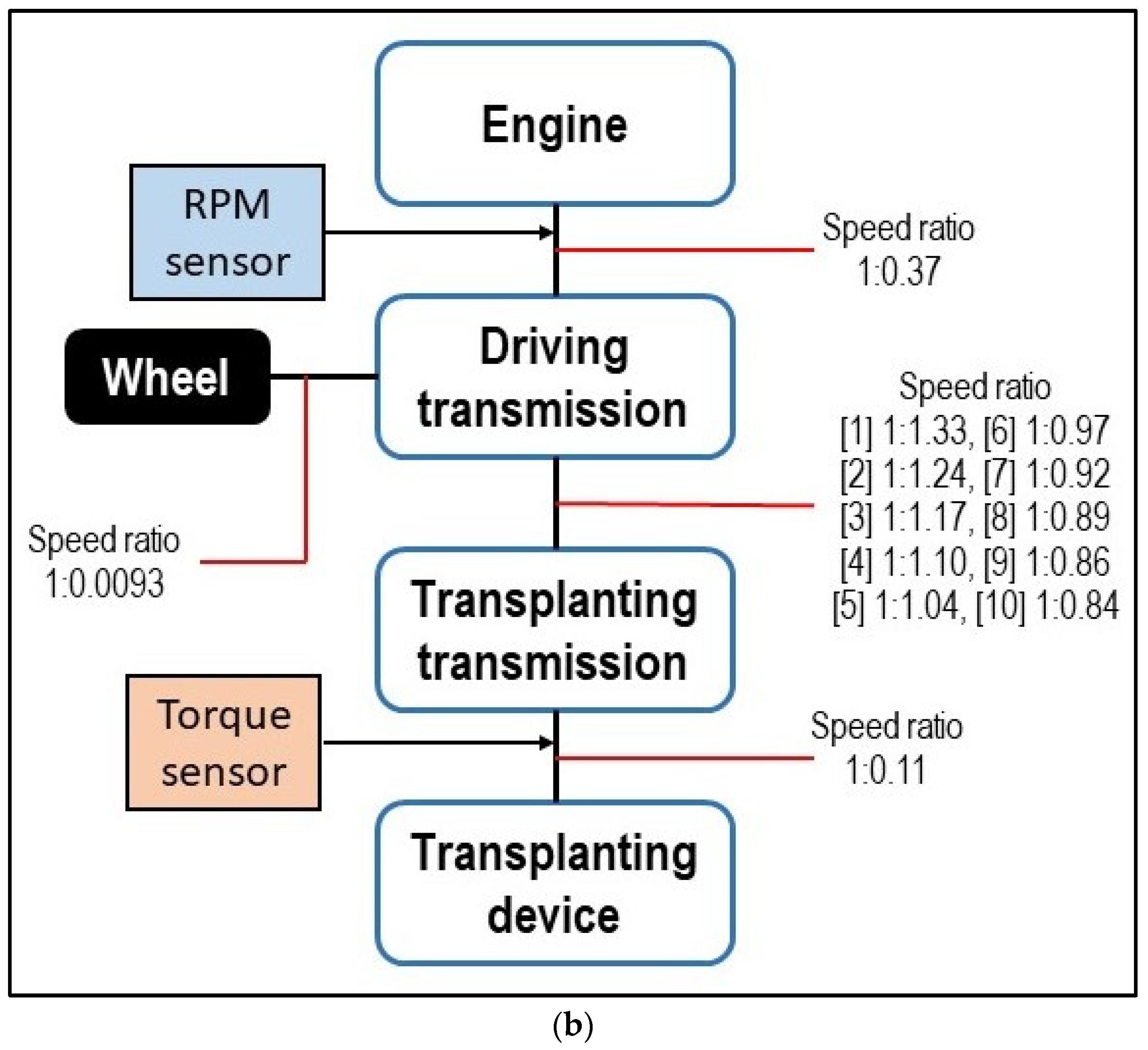
2.3. Measurement and Analysis
3. Results
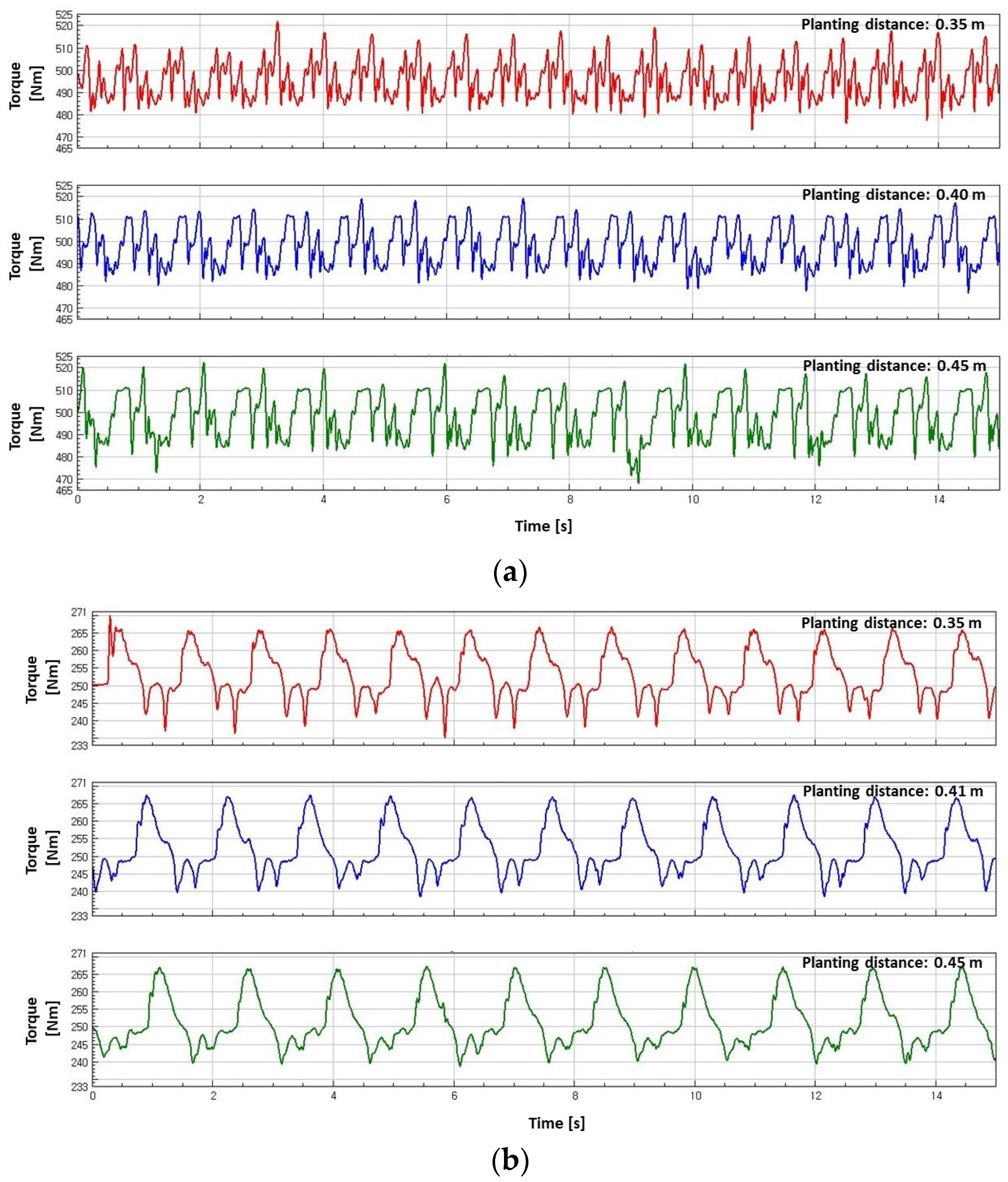
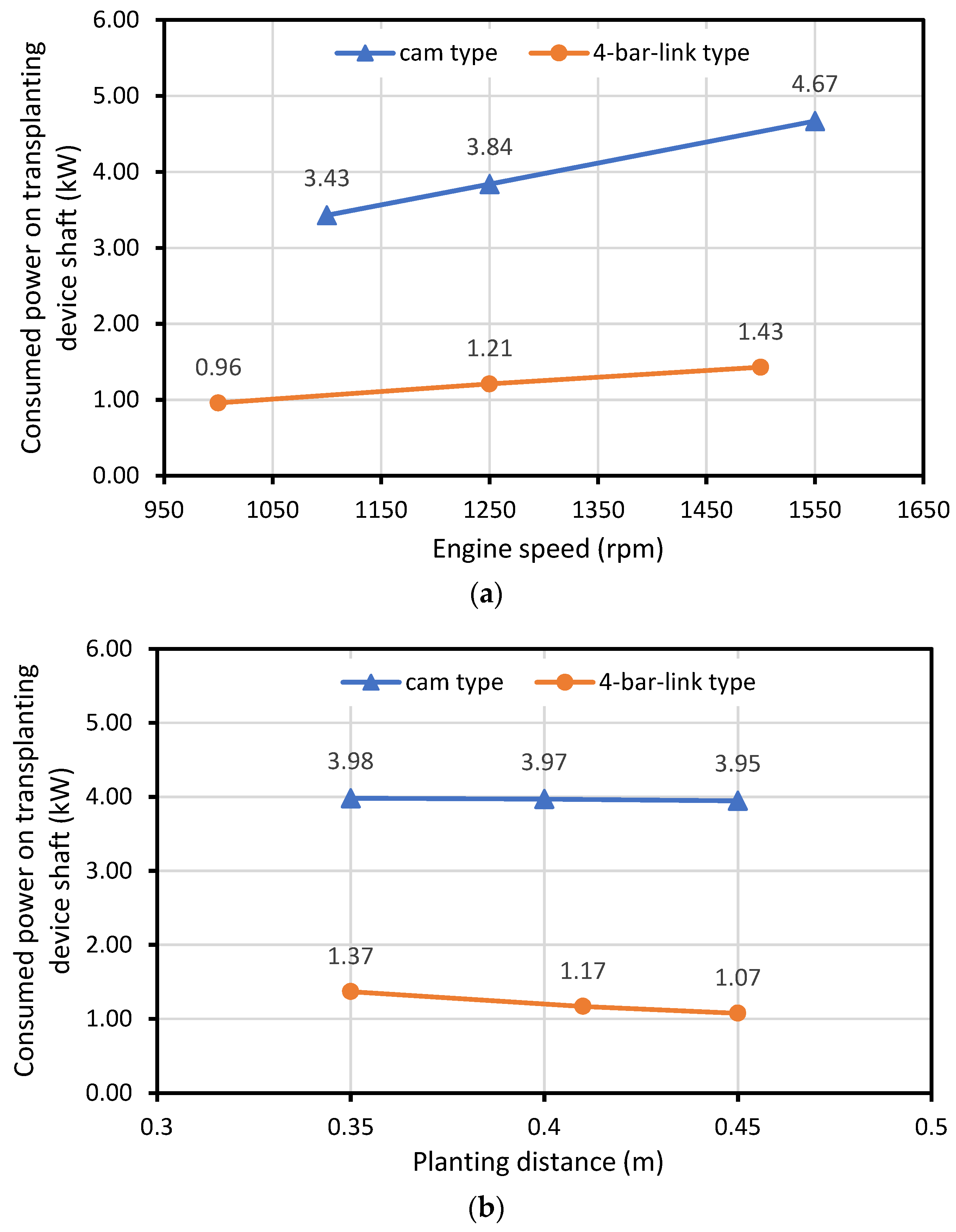
3.1. Torque and Consumed Power
3.2. Static Safety Factor
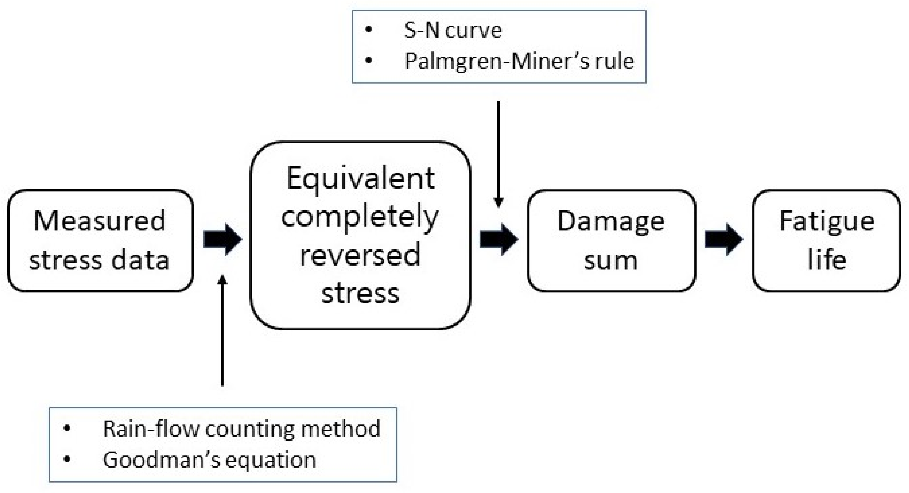
3.3. Fatigue Life
4. Conclusions
- Under similar operating conditions, the cam type had a greater torque and consumed more power than the four-bar-link type owing to its rigid and heavier design. The range of the consumed power on the transplanting device input shaft of the cam type was 3.32–4.68 kW, while it was 0.84–1.66 kW for the four-bar-link type. The consumed power on the transplanting device input shaft increased when the engine speed increased and the planting distance decreased for both types.
- The static safety factor was greater than 1.0 for both types at all measurement locations and under all working conditions. The minimum static safety factor for the cam type was 3.35 on the upper side of the transplanting hopper (S_4) at an engine speed of 1550 rpm and a planting distance of 0.35 m. For the four-bar-link type, the minimum static safety factor was 4.05 at one of the linkages (link D) at an engine speed of 1500 rpm and a planting distance of 0.41 m.
- The minimum fatigue life for the cam type was 95,603 years at the upper side of the transplanting hopper (S_3) at an engine speed of 1550 rpm and a planting distance of 0.35 m. The minimum fatigue life for the four-bar-link type was 196,000 years at the same location with the minimum static safety factor (link D) at an engine speed of 1500 rpm and a planting distance of 0.41 m.
- The rated work efficiencies of the cam and four-bar-link vegetable transplanters are similar. The cam type had a digital plant-spacing control device so that workers could work comfortably. However, considering the power consumption and price of the machine, the four-bar-link vegetable transplanter is highly economical.
Author Contributions
Funding
Institutional Review Board Statement
Informed Consent Statement
Data Availability Statement
Conflicts of Interest
References
- Kim, S.K.; Park, S.; Kwak, J.-H.; Choi, S.-K.; Chae, W.B.; Yang, E.Y.; Lee, M.J.; Jang, Y.; Seo, M.H.; Lee, S.H.; et al. Proper Plant Density for Mechanical Transplanting of Several Leafy Vegetables Under Korean Agricultural Condition. J. Biosyst. Eng. 2019, 44, 276–280. [Google Scholar] [CrossRef]
- Hwang, S.-J.; Park, J.-H.; Lee, J.-Y.; Shim, S.-B.; Nam, J.-S. Optimization of Main Link Lengths of Transplanting Device of Semi-Automatic Vegetable Transplanter. Agronomy. 2020, 10, 1938. [Google Scholar] [CrossRef]
- Khadatkar, A.; Mathur, S.M.; Gaikwad, B.B. Automation in Transplanting: A Smart Way of Vegetable Cultivation. Curr. Sci. 2018, 115, 1884–1892. [Google Scholar] [CrossRef]
- Rasool, K.; Islam, N.; Ali, M.; Jang, B.-E.; Khan, N.A.; Chowdhury, M.; Chung, S.-O.; Kwon, H.-J. Onion transplanting mechanisms: A review. Precis. Agric. Sci. Technol. 2020, 2, 196. [Google Scholar] [CrossRef]
- Kang, D.H.; Kim, D.E.; Lee, G.I.; Kim, Y.H.; Lee, H.J.; Min, Y.B. Development of a Vegetable Transplanting Robot. J. Biosyst. Eng. 2012, 37, 201–208. [Google Scholar] [CrossRef]
- Moon, S.D.; Min, Y.B.; Park, J.C. Analysis of working capacity of a hand-fed transplanter. J. Bio. Fac. Environ. 1997, 6, 159–167. Available online: https://www.koreascience.or.kr/article/JAKO199711922405384.pdf (accessed on 18 December 2022).
- Shao, Y.; Liu, Y.; Xuan, G.; Hu, Z.; Han, X.; Wang, Y.; Chen, B.; Wang, W. Design and Test of Multifunctional Vegetable Transplanting Machine. IFAC-PapersOnLine 2019, 52, 92–97. [Google Scholar] [CrossRef]
- Kumar, G.V.P.; Raheman, H. Vegetable Transplanters for Use in Developing Countries—A Review. Int. J. Veg. Sci. 2008, 14, 232–255. [Google Scholar] [CrossRef]
- Jo, J.S.; Okyere, F.G.; Jo, J.M.; Kim, H.T. A Study on improving the performance of the planting device of a vegetable trans-planter. J. Biosyst. Eng. 2018, 43, 202–210. [Google Scholar] [CrossRef]
- Min, Y.B.; Kang, J.K.; Ryu, C.S. Development Onion Transplanter: Analysis a Transplanting Locus on The Type of Transplanting Devices for a Vegetable Transplanter. J. Agric. Life Sci. 2015, 49, 289–294. [Google Scholar] [CrossRef]
- Sri, M.; Hwang, S.-J.; Nam, J.-S. Experimental Safety Analysis for Transplanting Device of the 4-Bar Link Type Semi-Automatic Vegetable Transplanter. Agronomy 2022, 12, 1890. [Google Scholar] [CrossRef]
- Park, J.-H.; Hwang, S.-J.; Nam, J.-S. Operational Characteristics of a Domestic Commercial Semi-automatic Vegetable Transplanter. J. Agric. Life Sci. 2018, 52, 127–138. [Google Scholar] [CrossRef]
- Park, J.-H.; Hwang, S.-J.; Nam, J.-S. Operational Characteristics of a Cam-type Vegetable Transplanter and Mechanism of a Transplanting Device. J. Agric. Life Sci. 2019, 53, 113–124. [Google Scholar] [CrossRef]
- Iqbal, Z.; Islam, N.; Ali, M.; Kiraga, S.; Kim, Y.-J.; Chung, S.-O. Theoretical Overturning Analysis of a 2.6-kW Two-Row Walking-Type Automatic Pepper Transplanter. J. Biosyst. Eng. 2022, 47, 79–91. [Google Scholar] [CrossRef]
- Sri, M.; Hwang, S.-J.; Nam, J.-S. Experimental safety analysis of transplanting device of the cam-type semi-automatic vegetable transplanter. J. Terramechanics 2022, 103, 19–32. [Google Scholar] [CrossRef]
- Kim, Y.-J.; Chung, S.-O.; Park, S.-J.; Choi, C.-H. Analysis of Power Requirement of Agricultural Tractor by Major Field Operation. J. Biosyst. Eng. 2011, 36, 79–88. [Google Scholar] [CrossRef]
- Lee, D.-H.; Kim, Y.-J.; Chung, S.-O.; Choi, C.-H.; Lee, K.-H.; Shin, B.-S. Analysis of the PTO load of a 75kW agricultural tractor during rotary tillage and baler operation in Korean upland fields. J. Terramechanics 2015, 60, 75–83. [Google Scholar] [CrossRef]
- Choudhary, S.; Upadhyay, G.; Patel, B.; Naresh; Jain, M. Energy Requirements and Tillage Performance Under Different Active Tillage Treatments in Sandy Loam Soil. J. Biosyst. Eng. 2021, 46, 353–364. [Google Scholar] [CrossRef]
- Koo, Y.M.; Kang, Y. Characteristics of Power and Fuel Use of a Tractor-Mounted Integrated Implement for Round Ridge Preparation. J. Biosyst. Eng. 2021, 46, 496–507. [Google Scholar] [CrossRef]
- Swe, K.M.; Islam, N.; Chowdhury, M.; Ali, M.; Wing, S.; Jun, H.-J.; Lee, S.-H.; Chung, S.-O.; Kim, D.-G. Theoretical Analysis of Power Requirement of a Four-Row Tractor-Mounted Chinese Cabbage Collector. J. Biosyst. Eng. 2021, 46, 139–150. [Google Scholar] [CrossRef]
- Shafaei, S.M.; Loghavi, M.; Kamgar, S. On the Reliability of Intelligent Fuzzy System for Multivariate Pattern Scrutinization of Power Consumption Efficiency of Mechanical Front Wheel Drive Tractor. J. Biosyst. Eng. 2021, 46, 1–15. [Google Scholar] [CrossRef]
- Koo, Y.M. PTO Torque and Draft Analyses of an Integrated Tractor-Mounted Implement for Round Ridge Preparation. J. Biosyst. Eng. 2022, 47, 330–343. [Google Scholar] [CrossRef]
- Lee, J.-Y.; Hwang, S.-J.; Nam, J.-S.; Kim, J.-G. Consumed-Power and Load Characteristics of Potato Harvesting Operation in Dry Field. Korean Soc. Manuf. Process. Eng. 2020, 19, 89–99. [Google Scholar] [CrossRef]
- Nam, J.-S.; Kang, D.-S.; Kang, Y.-S.; Kim, K.-U.; Kim, D.-C. Comparison of Work Performance of Crank-type and Rotary-type Rotavators in Korean Farmland Conditions. J. Biosyst. Eng. 2012, 37, 140–147. [Google Scholar] [CrossRef]
- Kim, M.-H.; Nam, J.-S.; Kim, D.-C. Comparison of Tillage and Loads Characteristics of Three Types of Rotavators: Rotary-type, Crank-type, and Plow-type. J. Biosyst. Eng. 2013, 38, 73–80. [Google Scholar] [CrossRef]
- Kim, J.G.; Kim, Y.J.; Kim, J.H.; Shin, B.S.; Nam, J.S. Consumed-power and load characteristics of a tillage operation in an upland field in Republic of Korea. J. Biosyst. Eng. 2018, 43, 83–93. [Google Scholar] [CrossRef]
- Lee, J.-Y.; Nam, J.-S. Load and Safety Analysis for Plow Operation in Dry Fields. Korean Soc. Manuf. Process. Eng. 2019, 18, 9–18. [Google Scholar] [CrossRef]
- Kim, W.S.; Chung, S.O.; Choi, C.H.; Cho, J.S.; Choi, D.S.; Kim, Y.J.; Lee, S.D.; Hong, S.J.; Koo, S.M. Analysis of the PTO Torque of a Transplanter by Planting Condition. J. Biosyst. Eng. 2016, 41, 313–318. [Google Scholar] [CrossRef]
- Kim, W.; Kim, Y.; Kim, Y.; Choi, C.; Inoue, E.; Okayasu, T. Analysis of the Load of a Transplanter PTO Shaft Based on the Planting Distance. J. Fac. Agric. Kyushu Univ. 2018, 63, 97–102. [Google Scholar] [CrossRef]
- Kim, W.-S.; Kim, Y.-S.; Kim, T.-J.; Nam, K.-C.; Kim, T.-B.; Han, T.-H.; Im, R.-G.; Kim, Y.-H. Effects of planting distance and depth on PTO load spectrum of a small riding-type transplanter. Int. J. Agric. Biol. Eng. 2020, 13, 57–63. [Google Scholar] [CrossRef]
- Lee, P.U.; So, J.H.; Nam, Y.S.; Choi, C.H.; Noh, H.S.; Shim, J.Y.; Hong, S.J. Power analysis of electric transplanter by planting distances. Korean J. Agric. Sci. 2018, 45, 290–297. [Google Scholar] [CrossRef]
- Lim, S.-J.; Kwon, H.-J.; Kang, Y.-S.; Lee, P.-U.; Kim, T.-J.; Kim, Y.-J.; Kim, Y.-S. Power Analysis of a 3-kW Class Motor-Driven Multipurpose Walking-Type Transplanter. J. Biosyst. Eng. 2019, 44, 135–145. [Google Scholar] [CrossRef]
- Downing, S.; Socie, D. Simple rainflow counting algorithms. Int. J. Fatigue 1982, 4, 31–40. [Google Scholar] [CrossRef]
- Rychlik, I. A new definition of the rainflow cycle counting method. Int. J. Fatigue 1987, 9, 119–121. [Google Scholar] [CrossRef]
- Juvinall, R.C.; Marshek, K.M. Machine Component Design, 5th ed.; John Wiley & Sons, Inc.: New York, NY, USA, 2020; pp. 338–340. [Google Scholar]
- Paraforos, D.S.; Griepentrog, H.W.; Vougioukas, S.G.; Kortenbruck, D. Fatigue life assessment of a four-rotor swather based on rainflow cycle counting. Biosyst. Eng. 2014, 127, 1–10. [Google Scholar] [CrossRef]
- Mattetti, M.; Molari, G.; Sereni, E. Damage evaluation of driving events for agricultural tractors. Comput. Electron. Agric. 2017, 135, 328–337. [Google Scholar] [CrossRef]


| Items | Specification | |
|---|---|---|
| Model | KP-100KR | |
| Manufacturer, nation | KUBOTA, Japan | |
| Length/width/height | mm | 2150/1360/1130 |
| Weight | kg | 280 |
| Engine | Rated power (kW) | 2.6 |
| Rated speed (rpm) | 1550 | |
| Wheel adjustment (inner/outer) | mm | 750–1000/1100–1500 |
| Planting distance | mm | 350–900 |
| Maximum working speed | m/s | 0.57 |
| Working efficiency | h/10a | 1.5–2.5 |
| Price | KRW | 13,000,000 |
| Items | Specification | |
|---|---|---|
| Model | KTP-30 | |
| Length/width/height | mm | 2125/1180/1510 |
| Weight | kg | 199 |
| Engine | Rated power (kW) | 3.4 |
| Rated speed (rpm) | 1800 | |
| Wheel adjustment (inner/outer) | mm | 360–750/1170–1550 |
| Planting distance | mm | 300–500 |
| Maximum working speed | m/s | 0.4 |
| Working efficiency | h/10a | 1.5–2.0 |
| Price | KRW | 4,900,000 |
| Strain Gauge Number | Locations | |
|---|---|---|
| Cam Type | Four-Bar-Link Type | |
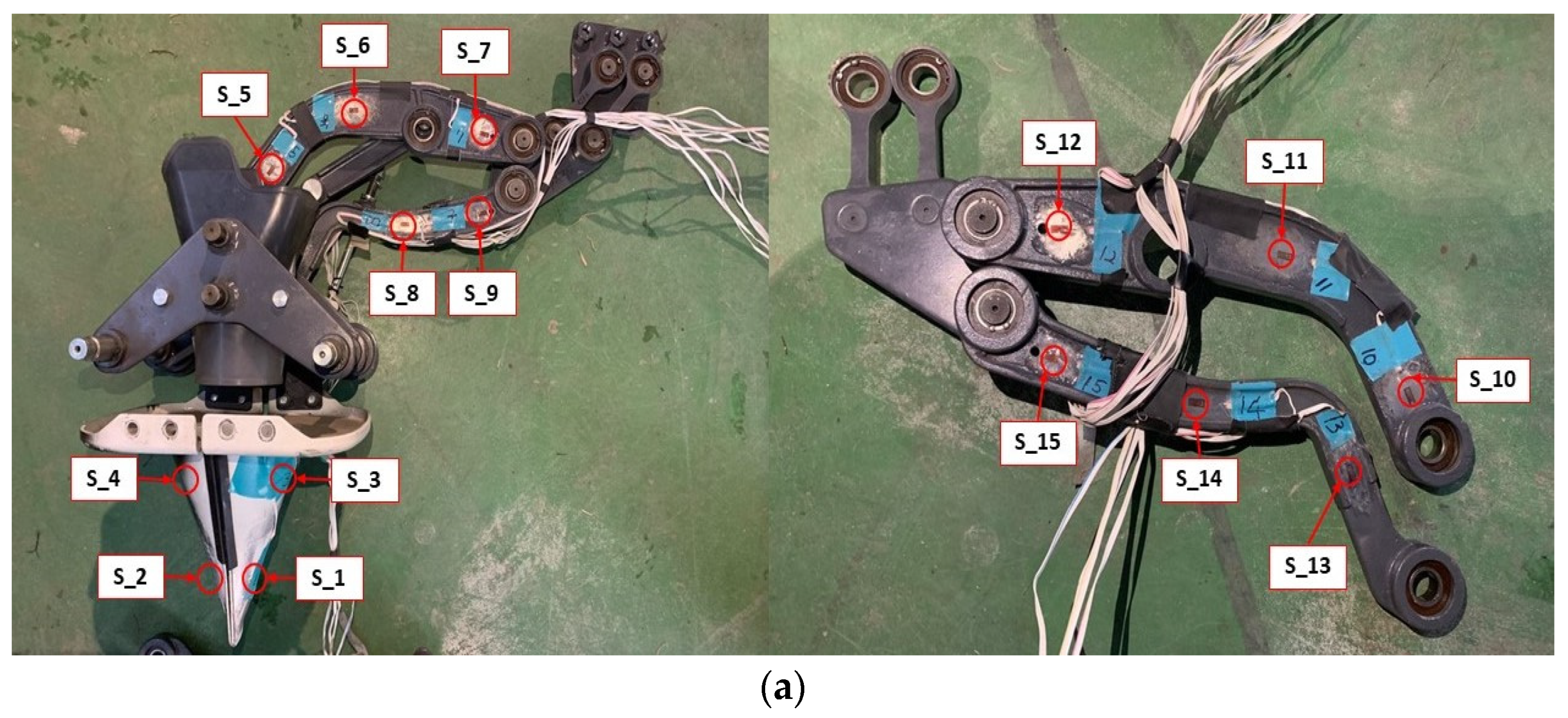
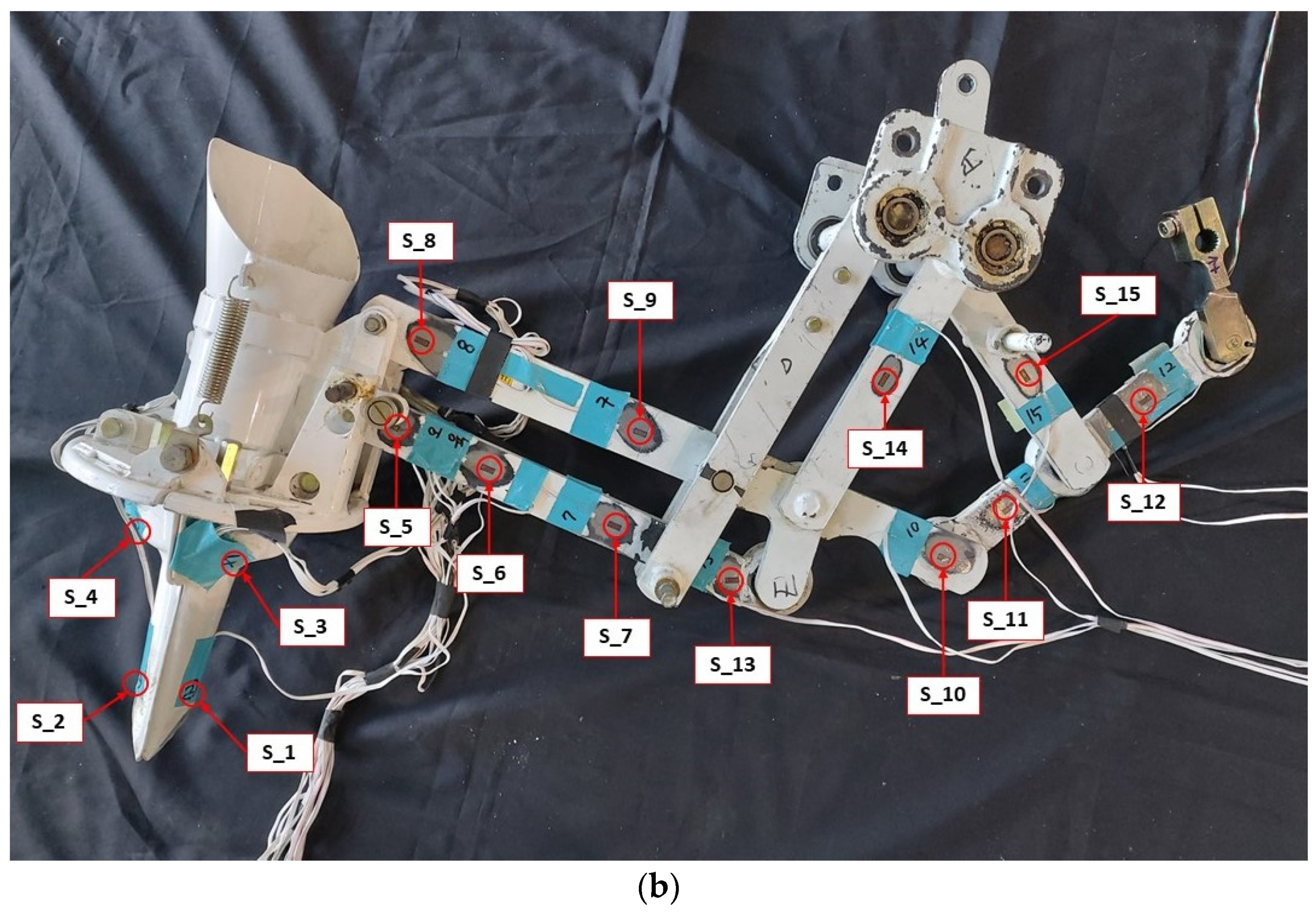
| S_1 | front lower side of transplanting hopper | front lower side of transplanting hopper |
| S_2 | back lower side of transplanting hopper | back lower side of transplanting hopper |
| S_3 | front upper side of transplanting hopper | front upper side of transplanting hopper |
| S_4 | back upper side of transplanting hopper | back upper side of transplanting hopper |
| S_5 | left side of left upper link | left side of sublink F |
| S_6 | middle side of left upper link | middle side of sublink F |
| S_7 | right side of left upper link | right side of sublink F |
| S_8 | middle side of left bottom link | left side of link B |
| S_9 | right side of left bottom link | right side of link B |
| S_10 | right side of right upper link | right side of link B |
| S_11 | middle side of right upper link | left side of link A |
| S_12 | left side of right upper link | right side of link A |
| S_13 | right side of right bottom link | right side of sublink F |
| S_14 | middle side of right bottom link | middle side of link D |
| S_15 | left side of right bottom link | middle side of link C |
| Type of Vegetable Transplanter | Engine Speed (rpm) | Planting Distance (m) | Torque of Transplanting Device Input Shaft (Nm) | Rotational Speed of Transplanting Device Input Shaft (rpm) | Consumed Power of the Transplanting Device Input Shaft (kW) |
|---|---|---|---|---|---|
| Cam | 1100 | 0.35 | 497.55 | 66.3 | 3.45 |
| 0.4 | 499.94 | 67.15 | 3.4 | ||
| 0.45 | 500.15 | 63.44 | 3.32 | ||
| 1250 | 0.35 | 496.1 | 73.64 | 3.83 | |
| 0.4 | 497.94 | 73.61 | 3.84 | ||
| 0.45 | 498.61 | 73.56 | 3.84 | ||
| 1550 | 0.35 | 494.83 | 89.94 | 4.66 | |
| 0.4 | 494.98 | 90.04 | 4.67 | ||
| 0.45 | 495.51 | 90.23 | 4.68 | ||
| Four-bar-link type | 1000 | 0.35 | 251.66 | 41.24 | 1.09 |
| 0.41 | 251.72 | 36.29 | 0.96 | ||
| 0.45 | 251.36 | 31.83 | 0.84 | ||
| 1250 | 0.35 | 253.2 | 50.78 | 1.35 | |
| 0.41 | 252.19 | 44.4 | 1.17 | ||
| 0.45 | 251.41 | 42.38 | 1.12 | ||
| 1500 | 0.35 | 252.01 | 63.02 | 1.66 | |
| 0.41 | 252.14 | 51.92 | 1.37 | ||
| 0.45 | 251.37 | 48.01 | 1.26 |
| Type of Vegetable Transplanter | Engine Speed (rpm) | Planting Distance (m) | S_1 | S_2 | S_3 | S_4 | S_5 | S_6 | S_7 | S_8 | S_9 | S_10 | S_11 | S_12 | S_13 | S_14 | S_15 |
|---|---|---|---|---|---|---|---|---|---|---|---|---|---|---|---|---|---|
| Cam Type | 1100 | 0.35 | 39.21 | 73.85 | 4.41 | 4.18 | 23.25 | 20.07 | 28.3 | 22.29 | 20.84 | 20 | 19.51 | 28.29 | 28.22 | 20.43 | 38.96 |
| 0.4 | 49.14 | 67.18 | 3.79 | 3.78 | 22.53 | 19.55 | 30.24 | 17.79 | 34.83 | 18.69 | 23.14 | 34.89 | 30.58 | 26.24 | 43.23 | ||
| 0.45 | 47.99 | 59.81 | 3.84 | 3.37 | 23.81 | 19.7 | 26.58 | 18.54 | 41.35 | 23.74 | 25.88 | 26.44 | 34.74 | 18.96 | 40.26 | ||
| 1250 | 0.35 | 45.94 | 68.86 | 3.83 | 4.89 | 17.69 | 17.24 | 26.08 | 17.47 | 15.79 | 21.02 | 14.07 | 18.46 | 27 | 30.45 | 47.71 | |
| 0.4 | 45.77 | 55.69 | 3.91 | 3.73 | 23.83 | 22.77 | 34.03 | 17.78 | 31.16 | 9.85 | 18.13 | 14.36 | 32.78 | 24.12 | 50.16 | ||
| 0.45 | 41.75 | 66.64 | 4.08 | 3.6 | 21.15 | 21.03 | 31.62 | 20.12 | 45.41 | 12.16 | 16.56 | 18.85 | 31.09 | 18.31 | 40.62 | ||
| 1550 | 0.35 | 36.31 | 60.12 | 3.7 | 3.35 | 16.62 | 16.87 | 28.26 | 15.66 | 27.09 | 18.04 | 14.86 | 20.33 | 26.79 | 21.51 | 36.53 | |
| 0.4 | 41.21 | 47.58 | 3.59 | 3.61 | 19.89 | 17.6 | 27.99 | 13.51 | 32.8 | 11.74 | 13.78 | 14.37 | 27.87 | 22.74 | 39.35 | ||
| 0.45 | 38.12 | 76.39 | 3.52 | 4.28 | 17.56 | 18.44 | 30.02 | 13.32 | 28.9 | 11.74 | 11.36 | 14.82 | 32.75 | 25.83 | 40.83 | ||
| Four-Bar-Link Type | 1000 | 0.35 | 61.42 | 72.83 | 8.12 | 15.52 | 5.03 | 5.33 | 6.09 | 15.66 | 8.61 | 8.49 | 19.12 | 8.81 | 18.67 | 6.55 | 5.23 |
| 0.41 | 60.7 | 62.83 | 8.28 | 13.65 | 4.41 | 4.67 | 5.26 | 10.83 | 7.54 | 8.17 | 16.97 | 6.79 | 13.98 | 4.29 | 4.95 | ||
| 0.45 | 46.29 | 55.6 | 17.23 | 18.25 | 6.73 | 6.95 | 7.67 | 18.54 | 13.7 | 10.29 | 28.01 | 6.28 | 21.95 | 6.54 | 5.11 | ||
| 1250 | 0.35 | 60.46 | 62.32 | 9.58 | 10.38 | 4.43 | 4.67 | 5.15 | 15.82 | 8.41 | 6.4 | 15.19 | 5.53 | 12.32 | 4.47 | 5.05 | |
| 0.41 | 88.82 | 67.85 | 14.3 | 14.82 | 5.67 | 5.83 | 6.33 | 16.78 | 10.27 | 8.2 | 22.91 | 5.56 | 17.58 | 5.02 | 5.02 | ||
| 0.45 | 70.81 | 89.57 | 15.55 | 16.44 | 6.48 | 6.68 | 7.35 | 17.41 | 12.06 | 9.49 | 22.61 | 5.88 | 20.43 | 5.24 | 5.04 | ||
| 1500 | 0.35 | 82.72 | 68.91 | 16.21 | 18.62 | 7.78 | 8.26 | 9.5 | 20.46 | 11.75 | 8.97 | 11.88 | 6.03 | 22.58 | 6.36 | 5.19 | |
| 0.41 | 69.72 | 75.16 | 9.89 | 10.46 | 4.63 | 4.76 | 5.17 | 12.94 | 8.37 | 6.42 | 13.94 | 4.89 | 12.72 | 4.05 | 4.95 | ||
| 0.45 | 85.58 | 94.2 | 20.95 | 21.66 | 7.61 | 8.13 | 9.12 | 19.21 | 10.45 | 11.38 | 22.18 | 6 | 26.31 | 6.68 | 5.02 |
| Type of Vegetable Transplanter | Engine Speed (rpm) | Planting Distance (m) | S_1 | S_2 | S_3 | S_4 | S_5 | S_6 | S_7 | S_8 | S_9 | S_10 | S_11 | S_12 | S_13 | S_14 | S_15 |
|---|---|---|---|---|---|---|---|---|---|---|---|---|---|---|---|---|---|
| Cam Type | 1100 | 0.35 | 1.60E + 11 | 1.10E + 13 | 1.63E + 05 | 4.52E + 05 | 8.00E + 08 | 4.00E + 08 | 2.00E + 09 | 7.00E+08 | 5.80E + 10 | 3.00E + 09 | 4.00E + 08 | 5.00E + 09 | 2.00E + 09 | 7.90E + 09 | 1.70E + 10 |
| 0.4 | 2.30E + 11 | 7.70E + 12 | 2.28E + 05 | 1.00E + 06 | 5.00E + 08 | 6.00E + 08 | 1.00E + 10 | 1.00E + 09 | 8.10E + 10 | 3.00E + 09 | 4.00E + 09 | 1.00E + 11 | 1.30E + 10 | 3.00E + 10 | 5.30E + 10 | ||
| 0.45 | 1.30E + 11 | 6.30E + 12 | 1.66 E + 05 | 3.87E + 05 | 5.00E + 08 | 6.00E + 08 | 9.00E + 09 | 1.00E + 09 | 9.40E + 10 | 6.00E + 09 | 5.00E + 09 | 4.00E + 10 | 2.30E + 10 | 7.00E + 09 | 3.10E + 10 | ||
| 1250 | 0.35 | 7.70E + 10 | 6.50E + 12 | 1.48 E + 05 | 8.69E + 05 | 2.00E + 08 | 5.00E + 08 | 4.00E + 09 | 6.00E + 08 | 5.70E + 09 | 5.00E + 09 | 2.00E + 08 | 3.00E + 09 | 4.60E + 09 | 5.40E + 09 | 3.40E + 10 | |
| 0.4 | 1.90E + 11 | 1.30E + 13 | 3.03 E + 05 | 4.41E + 05 | 1.00E + 09 | 1.00E + 09 | 3.00E + 10 | 2.00E + 09 | 1.10E + 11 | 1.00E + 08 | 1.00E + 09 | 1.00E + 09 | 2.60E + 10 | 1.10E + 10 | 3.70E + 10 | ||
| 0.45 | 6.90E + 10 | 3.50E + 13 | 2.79 E + 05 | 7.00E + 05 | 8.00E + 08 | 8.00E + 08 | 2.00E + 10 | 2.00E + 09 | 1.80E + 11 | 6.00E + 08 | 5.00E + 08 | 3.00E + 09 | 1.70E + 10 | 4.10E + 09 | 3.40E + 10 | ||
| 1550 | 0.35 | 4.30E + 10 | 1.90E + 12 | 9.56 E + 04 | 3.10E + 05 | 2.00E + 08 | 7.00E + 08 | 4.00E + 09 | 3.00E + 08 | 5.00E + 10 | 1.00E + 09 | 1.00E + 08 | 1.00E + 09 | 1.60E + 09 | 1.30E + 09 | 1.10E + 10 | |
| 0.4 | 5.30E + 10 | 2.10E + 12 | 9.72 E + 04 | 4.80E + 05 | 4.00E + 08 | 3.00E + 08 | 4.00E + 09 | 4.00E + 08 | 4.00E + 10 | 4.00E + 08 | 2.00E + 08 | 4.00E + 08 | 5.60E + 09 | 1.10E + 09 | 1.50E + 10 | ||
| 0.45 | 5.40E + 10 | 2.90E + 12 | 2.08 E + 05 | 5.08E + 05 | 1.00E + 08 | 3.00E + 08 | 5.00E + 09 | 5.00E + 08 | 5.80E + 10 | 4.00E + 08 | 4.00E + 07 | 3.00E + 08 | 6.20E + 09 | 2.00E + 09 | 1.80E + 10 | ||
| Four-Bar-Link Type | 1000 | 0.35 | 3.60E + 13 | 1.30E + 14 | 2.00E + 09 | 9.00E + 10 | 1.00E + 07 | 2.00E + 07 | 5.00E + 07 | 9.00E + 08 | 4.00E + 07 | 4.00E + 07 | 2.00E + 09 | 8.00E + 07 | 1.30E + 10 | 1.30E + 07 | 1.25E + 06 |
| 0.41 | 4.20E + 12 | 1.50E + 13 | 1.00E + 09 | 1.00E + 10 | 1.00E + 06 | 2.00E + 06 | 4.00E + 06 | 1.00E + 08 | 5.49E + 06 | 1.00E + 07 | 8.00E + 08 | 1.00E + 07 | 7.70E + 08 | 6.22E + 05 | 9.89E + 05 | ||
| 0.45 | 1.30E + 15 | 5.20E + 15 | 2.00E + 12 | 2.00E + 12 | 5.00E + 08 | 7.00E + 08 | 9.00E + 08 | 1.00E + 07 | 1.50E + 09 | 2.00E + 08 | 1.00E + 10 | 4.00E + 07 | 1.20E + 11 | 2.20E + 08 | 1.13E + 06 | ||
| 1250 | 0.35 | 5.90E + 12 | 3.50E + 12 | 5.00E + 09 | 4.00E + 09 | 7.79E + 05 | 1.00E + 06 | 2.00E + 06 | 2.00E + 08 | 5.49E + 06 | 7.00E + 06 | 2.00E + 08 | 1.00 E + 06 | 2.50E + 08 | 3.05E + 05 | 7.83E + 05 | |
| 0.41 | 3.20E + 13 | 5.20E + 14 | 3.00E + 10 | 2.00E + 10 | 5.00E + 06 | 6.00E + 06 | 1.00E + 07 | 5.00E + 08 | 1.80E + 07 | 2.00E + 07 | 1.00E + 09 | 2.00E + 06 | 2.10E + 09 | 6.48E + 05 | 9.36E + 05 | ||
| 0.45 | 9.40E + 12 | 3.70E + 15 | 2.00E + 11 | 5.00E + 10 | 2.00E + 07 | 2.00E + 07 | 5.00E + 07 | 1.00E + 09 | 9.30E + 07 | 9.00E + 07 | 2.00E + 09 | 4.00E + 06 | 1.00E + 10 | 2.54E + 06 | 9.29E + 05 | ||
| 1500 | 0.35 | 4.00E + 13 | 4.00E + 12 | 5.00E + 10 | 8.00E + 10 | 1.00E + 08 | 2.00E + 08 | 3.00E + 08 | 3.00E + 09 | 1.10E + 08 | 2.00E + 07 | 2.00E + 08 | 2.00E + 06 | 3.20E + 10 | 1.74E + 06 | 7.17E + 05 | |
| 0.41 | 4.50E + 12 | 3.70E + 12 | 9.00E + 09 | 3.00E + 09 | 1.00E + 06 | 1.00E + 06 | 3.00E + 06 | 1.00E + 08 | 4.51E + 06 | 7.00E + 06 | 2.00E + 08 | 1.00E + 06 | 2.60E + 08 | 1.96E + 05 | 6.85E + 05 | ||
| 0.45 | 5.00E + 13 | 1.90E + 15 | 4.00E + 11 | 8.00E + 10 | 6.00E + 07 | 9.00E + 07 | 2.00E + 08 | 3.00E + 09 | 6.20E + 07 | 1.00E + 08 | 2.00E + 09 | 4.00E + 06 | 2.30E + 10 | 5.88E + 06 | 8.97E + 05 |
Disclaimer/Publisher’s Note: The statements, opinions and data contained in all publications are solely those of the individual author(s) and contributor(s) and not of MDPI and/or the editor(s). MDPI and/or the editor(s) disclaim responsibility for any injury to people or property resulting from any ideas, methods, instructions or products referred to in the content. |
© 2023 by the authors. Licensee MDPI, Basel, Switzerland. This article is an open access article distributed under the terms and conditions of the Creative Commons Attribution (CC BY) license (https://creativecommons.org/licenses/by/4.0/).
Share and Cite
Markumningsih, S.; Hwang, S.-J.; Kim, J.-H.; Jang, M.-K.; Shin, C.-S.; Nam, J.-S. Comparison of Consumed Power and Safety of Two Types of Semi-Automatic Vegetable Transplanter: Cam and Four-Bar Link. Agriculture 2023, 13, 588. https://doi.org/10.3390/agriculture13030588
Markumningsih S, Hwang S-J, Kim J-H, Jang M-K, Shin C-S, Nam J-S. Comparison of Consumed Power and Safety of Two Types of Semi-Automatic Vegetable Transplanter: Cam and Four-Bar Link. Agriculture. 2023; 13(3):588. https://doi.org/10.3390/agriculture13030588
Chicago/Turabian StyleMarkumningsih, Sri, Seok-Joon Hwang, Jeong-Hun Kim, Moon-Kyeong Jang, Chang-Seop Shin, and Ju-Seok Nam. 2023. "Comparison of Consumed Power and Safety of Two Types of Semi-Automatic Vegetable Transplanter: Cam and Four-Bar Link" Agriculture 13, no. 3: 588. https://doi.org/10.3390/agriculture13030588
APA StyleMarkumningsih, S., Hwang, S.-J., Kim, J.-H., Jang, M.-K., Shin, C.-S., & Nam, J.-S. (2023). Comparison of Consumed Power and Safety of Two Types of Semi-Automatic Vegetable Transplanter: Cam and Four-Bar Link. Agriculture, 13(3), 588. https://doi.org/10.3390/agriculture13030588