Article

Development and Numerical Simulation of a Precision Strip-Hole Layered Fertilization Subsoiler While Sowing Maize

1
College of Engineering, Anhui Agricultural University, Hefei 230036, China
2
Anhui Provincial Engineering Laboratory of Intelligent Agricultural Machinery, Hefei 230036, China
3
Institute of Artificial Intelligence, Hefei Comprehensive National Science Center, Hefei 230036, China
*
Author to whom correspondence should be addressed.
Agriculture 2022, 12(7), 938; https://doi.org/10.3390/agriculture12070938
Submission received: 3 June 2022 / Revised: 26 June 2022 / Accepted: 27 June 2022 / Published: 28 June 2022

Abstract

:
The traditional fertilizer application methods have serious problems of environmental pollution and soil degradation due to low utilization rates in the Huang–Huai–Hai Plain of China. In this study, the conservation tillage strip-hole layered fertilization method was proposed and a precision strip-hole layered fertilizer subsoiler was designed. To meet the requirements for deep tillage strip-hole layered fertilizer application, theoretical analysis and parameter calculations were first carried out on the fertilizer application type hole wheel, and then the main factors affecting the fertilizer application effect of a strip-hole layered fertilizer shovel were analyzed. The effect of forwarding speed, angle of fertilizer tube installation (AFT) and angle of unloading fertilizer (AUF) on the middle and lower layers of the fertilizer distribution length (FDT) and fertilization amount deviation stability coefficient (FADSC) was studied using the discrete element method (DEM). The three-factor three-level full-factors test design method was adopted. Simulation results showed that the FDT and the FADSC increased as the forward speed increased; the FDT decreased as the AFT and the AUF increased; an increased FADSC was observed at a middle angle of the AFT and the AUF. The minimum FADSC was obtained for a combination of parameters with a forward speed of 2 km/h, the AFT of 35° and the AUF of 60°, corresponding to the FADSC of 2.49% in the middle layer and 2.93% in the lower layer while satisfying the FDT condition. The results of the field trials showed that the FADSC was 11.36% and 12.42%, respectively, an increase of 8.87% and 9.49%, respectively, compared to the simulation results, validating the simulation model. The new way of fertilizer application methods and a theoretical basis were provided for the design of hole application machinery.

1. Introduction

As China’s second-largest grain crop, increasing maize production is vital for food development [1,2,3]. Maize requires more fertilizer than other grains and legumes, and a reasonable amount of fertilizer and fertilizer application will improve the utilization efficiency of fertilizers, increase maize yields and improve maize quality [4,5]. At present, the main method of fertilizer application for maize mechanization is strip fertilization, which causes a waste of fertilizer, far from the roots, due to the large spacing between the maize plants [6]. A strip-hole layered fertilizer subsoiler can apply fertilizer in different soil layers at once, which can improve the utilization efficiency of fertilizers, avoid waste and reduce the number of operations. The one-time layered application of fertilizer improves the utilization efficiency of fertilizers and maize yield, enables the lighter production of maize and the efficient use of fertilizer nutrients, avoids the burning and rotting of seeds, reduces fertilizer use, saves costs, and alleviates agricultural environmental pollution [7,8]. In recent years, slow-release fertilizers have been rapidly developed as a new way of solving the problem of long and stable fertilization periods, often due to tall plants, inconvenient late application operations, labor shortages and high labor costs, strip-hole layering can be combined with slow-release fertilizers to improve the utilization efficiency of fertilizers, increase yield, efficiency and reduce environmental pollution [9,10,11].
Deep tillage can improve soil structure, increase soil water and moisture storage capacity, reduce soil weight at the bottom of the plow and increase the utilization of nutrients in the soil, which can effectively protect the quality of arable land and promote sustainable agricultural development, providing optimal conditions for seed germination and then promote the growth of crop roots and increase crop yield [12,13,14]. In recent years, scholars at home and abroad have carried out a lot of research on deep tillage operations, and deep vertical rotary tillage has increased the accumulation of stem and root dry matter in crops and improved the seed tube speaking rate and yield [15]; field management operations can deepen crop root growth and alter soil porosity, affecting water infiltration, storage and crop water uptake [16]. Deep tillage management strategies can mix soils at different depths and maintain the long-term productivity of no-till systems, providing effective solutions to address soil water resistance, herbicide weed resistance, subsoil acidity, and compaction [17]; the subsoil stores a large number of nutrients required by the crop, and deep tillage can be a tool to increase the absorption of subsoil resources for the crop and improve its resilience and ability to adapt to different climate changes [18].
The key to layered fertilization is how the fertilizer is applied in the required manner. Fertilizer should be applied in layers to increase the amount of fertilizer from nodulation to flowering to ensure the good development of the maize ears and reduce the amount of fertilizer applied during the seedling and flowering period so as not to jeopardize the yield and safety of the maize, which is conducive to promoting seed filling, increasing the number of grains set and grain weight and achieving the goal of high maize yield [19]. A fertilizer application volume adjustable layered fertilizer applicator was designed to achieve the precise application of fertilizer according to the growth pattern of maize by adjusting the installation angle of the fertilizer tube, and the length of the fertilizer application piece [20]. A depth-adjustable layered fertilizer opener has been developed to meet the needs of trenching and fertilizer application in potato cultivation [21,22]. A crank-rocker type cavity fertilizer application device was designed to meet the agronomic requirements and reduce the resistance between the machine and the soil through simulation and testing [23]. Simulation and validation of the maize ortho-layered hole application mechanism were carried out using the SPH algorithm [24]. Zhang Junxiong designed a cavity tray-type precision cavity fertilizer application device, which can achieve precision, stable fertilizer extraction, and improve the fertilizer utilization rate [25]. The above scholars have conducted research trials on layered fertilization and hole application but have not studied the combination of hole application and layered fertilization.
In this paper, a new fertilizer application method is proposed and a precision strip-hole layered fertilization subsoiler is designed to meet the fertilizer requirements of summer maize during different growth periods and to improve the fertilizer utilization rate. The discrete element method (DEM) is used to simulate the fertilizer formation and to verify the performance of the strip-hole layered fertilizer application device through field trials.

2. Materials and Methods

2.1. Agronomic Requirements

Summer maize is still fertilized in the traditional phased manner, meaning that fertilizer is applied once at sowing and a follow-up application of fertilizer at mid-maize in the Huang–Huai–Hai Plain of China [26,27]. This method of fertilization directly affects the healthy growth of maize, often resulting in the burning of seeds and seedlings, inhibiting root growth. While maize does not receive sufficient nutrients during tasseling and flowering, resulting in the quality of maize being affected, as well as the high density of maize in the middle of the season, which is not suitable for the population topdressing, population topdressing is time-consuming and labor-intensive, and also results in a waste of resources. The use of strip-hole layered fertilization technology is a one-time proportional layering of fertilizer required for the maize growth cycle in the soil, where the base fertilizer is applied in strips, and the additional fertilizer and substrate fertilizer are applied in holes, which will not cause burning of seedlings and rotten seedlings but will also ensure that the maize seedling rate, and the best results, in terms of nutrient uptake and yield, increase in each growth period of the maize. The base fertilizer is applied by strip fertilizer, the lateral distance L1 between the fertilizer and seed is 50 mm when fertilizer is applied, and the application depth H1 is 50 mm; this can effectively avoid burning the seed. As shown in Figure 1, hole fertilization was used for topdressing and bottom fertilizer, the fertilizer is applied at a depth of H2 and H3 of 110 mm and 160 mm, respectively [1]. This is located at the bottom of the root system of maize at the nodulation stage and maize at the grouting period, avoiding the waste of fertilizer, improving the efficiency of fertilizer use, reducing the cost of maize production, helping to increase yields and improving the quality of maize, and greatly reducing the environmental pollution caused by the extensive use of fertilizer.

2.2. Theory and Calculation of Model

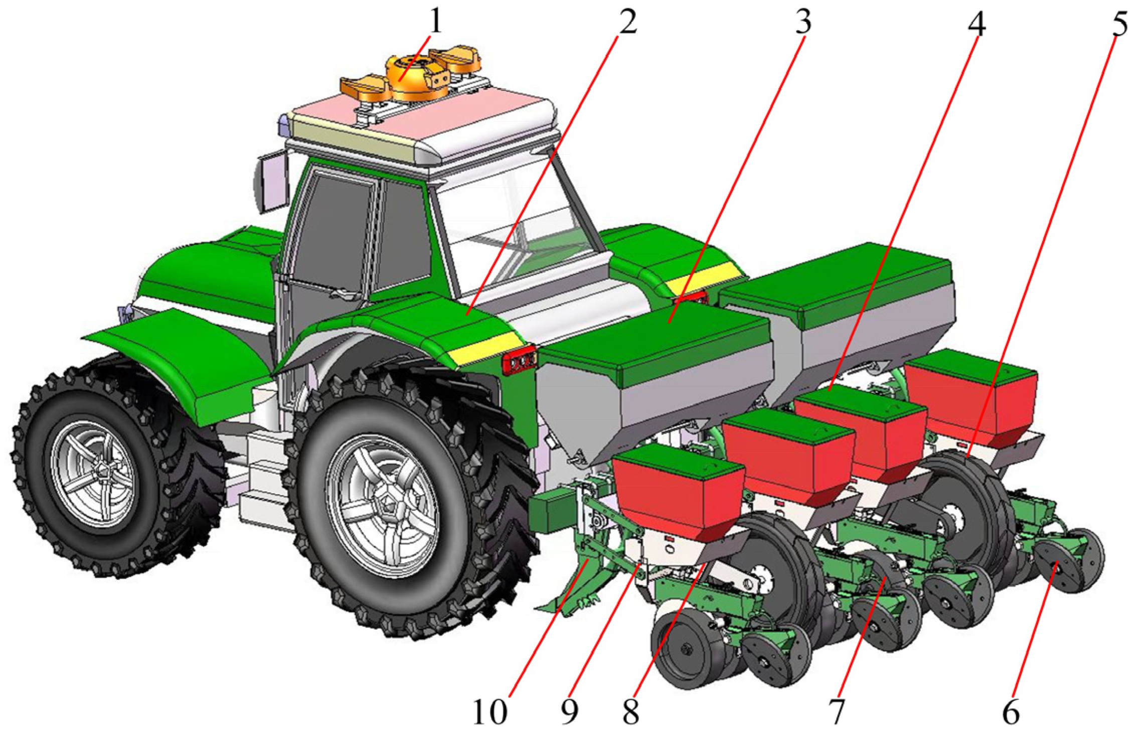
2.2.1. Design of Layered Fertilizer No-Tillage Planter

The schematic diagram of the overall structure of the maize layered fertilizer no-till planter is shown in Figure 2. It is mainly composed of the tractor, Beidou navigation receiver, fertilizer and seed boxes, subsoiler and fertilizer application tubes, furrowing and seeding units, depth-limiting wheels, mulching ballast wheels, driven-ground wheels, racks, etc. The no-till planter is hooked up to the rear suspension of the tractor via a three-point suspension frame, the subsoiler and fertilizer application tube is bolted to the frame, the seeding units are connected to the frame via a profiling structure when the machine is in operation, the ground wheels are rotated by ground friction to discharge fertilizer and drop seeds; the subsoil device and fertilizer tube installed at the bottom of the rack are used to fertilize the subsoil and ditches before sowing, deep tillage in the strips facilitates seed growth and germination; the double discs in the front of the seed rower compact and cut the straw stubble and open the seed trench, the seeds are discharged through the seed guide tube into the soil above the side of the fertilizer, the mulching and suppression wheels then complete the mulching and suppression of the maize seeds.

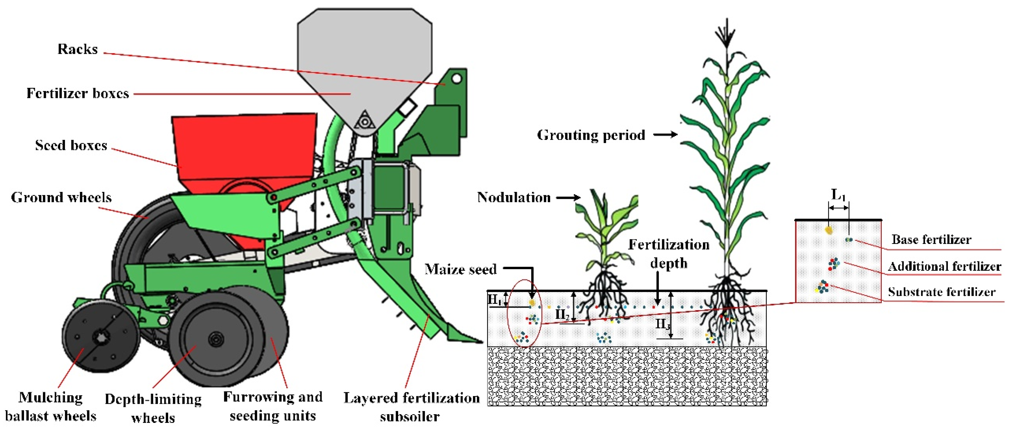
2.2.2. Precision Strip-Hole Layered Fertilizer Subsoiler

The precision strip-hole layered fertilization subsoiler is mainly composed of a soil divider, wing shovel, fertilizer application tube, drive shaft, motor, reversing device, fertilizer brush, and fertilizer application type hole wheel, as shown in Figure 3. The precision strip-hole layered fertilization subsoiler relies on tractor power as well as motor power for fertilizer application. The tractor drives the no-till planter forward and the Beidou Navigation receiver receives the forward speed signal from the tractor and transmits it to the communication controller, which then processes and controls the motor speed to control the hole wheel angular speed. The subsoiler loosens the subsoil and makes a fertilizer trench, the fertilizer particles enter the fertilizer tube through the fertilizer pipe and slide along the wall of the fertilizer tube under the action of gravity, and the fertilizer is divided into two parts at the partition, one part flows to the upper layer of the fertilizer outlet and falls into the upper layer of soil, the other part flows to the type hole wheel; when the fertilizer flows to the rotating type hole wheel, the drive shaft is driven by the motor and the power is transmitted to the commutator. The fertilizer brush prevents the fertilizer from interfering with the fertilizer tube and causing the fertilizer to become stuck in the type hole wheel, and the fertilizer flows out of the middle and lower fertilizer outlets into the middle and lower soil layers. The hole application stops discharging fertilizer when the hole is turned to a closed position.

2.2.3. Design and Parametric Analysis of Key Components

The structure, size, and volume of the fertilizer type hole wheel, the force, arrangement state, and the stability degree of fertilizer particles in the bore affect the performance of fertilizer hole formation and the stability of fertilizer application. The fertilizer application rate for maize is generally 450~750 kg/hm2 in the Huang–Huai–Hai Plain of China, fertilizer is applied in layers of strips and holes to ensure the amount of fertilizer required at each stage of the maize growth cycle, and the middle and lower layers are fertilized by holes so that the space for the fertilizer effect of the holes coincides with the space for the growth of the maize root system, which can improve the utilization efficiency of fertilizers and reduce the amount of fertilizer applied. Therefore, the strip-hole layered fertilizer application device was designed to meet the fertilizer requirement of maize at a spacing of 600 mm × 250 mm, with 6.8–10.8 g of fertilizer applied per hole, respectively, to meet the fertilizer application in the middle and lower layers. To facilitate the filling and smooth discharge of the fertilizer in the hole, and in conjunction with previous research [28], the type hole wheel designed in this paper is an inclined parabolic hole with the cross-sectional shape, shown in Figure 4.
The volume of fertilizer to be discharged from each hole of the type hole wheel depends on the volume, and to facilitate the smooth discharge of fertilizer from the hole, the volume is calculated using the formula:
V 1 = 2 3 l a h a b a
where V1 is the volume of the profiled hole (mm3); la is the width of the profiled hole (mm); ha is the depth of the profiled hole (mm); ba is the length of the profiled hole (mm).
Based on a fertilizer application rate of 6.8–10.8 g per hole, the width of the profiled hole is 16–27 mm, the depth of the profiled hole is 7–12 mm and the length of the profiled hole is 35 mm. To ensure that the fertilizer is discharged in one go from the wheel, the maximum number of holes to be discharged is four, based on the width, depth and length of the profile holes and taking into account the thickness of the fertilizer tube. Assuming that the fertilizer particles can be discharged quickly and ignoring air resistance, the fertilizer discharge cycle for a single hole can be expressed as
t = t 1 + t 2 = l 1 v 1
where t is the drainage cycle of single cavity fertilizers (s); t1 is the time between the transfer of the fertilizer application hole to the discharge area and the complete discharge of the fertilizer (s); t2 is the time between the complete discharge of fertilizer from the application hole and the start of the next application hole into the discharge zone (s); l1 is the maize spacing, mm; v1 is the forward speed (mm/s).
The above equation shows that the degree of dispersion of the fertilizer in the fertilizer furrow is related to the t1/t positive correlation, when the machine is working, the maize plant distance l1 and the machine working speed v1 are certain; t is a constant, the smaller the number of fertilizer type holes Z, t2 the larger, t1 the smaller, the smaller the degree of fertilizer dispersion, to ensure the good operational effect of fertilizer application in the middle and lower holes it is determined that the number of type holes on the fertilizer type hole wheel is two, and the operating speed is 1–3 km/h, corresponding to the fertilizer type hole wheel speed of 6.67–20 r/min.

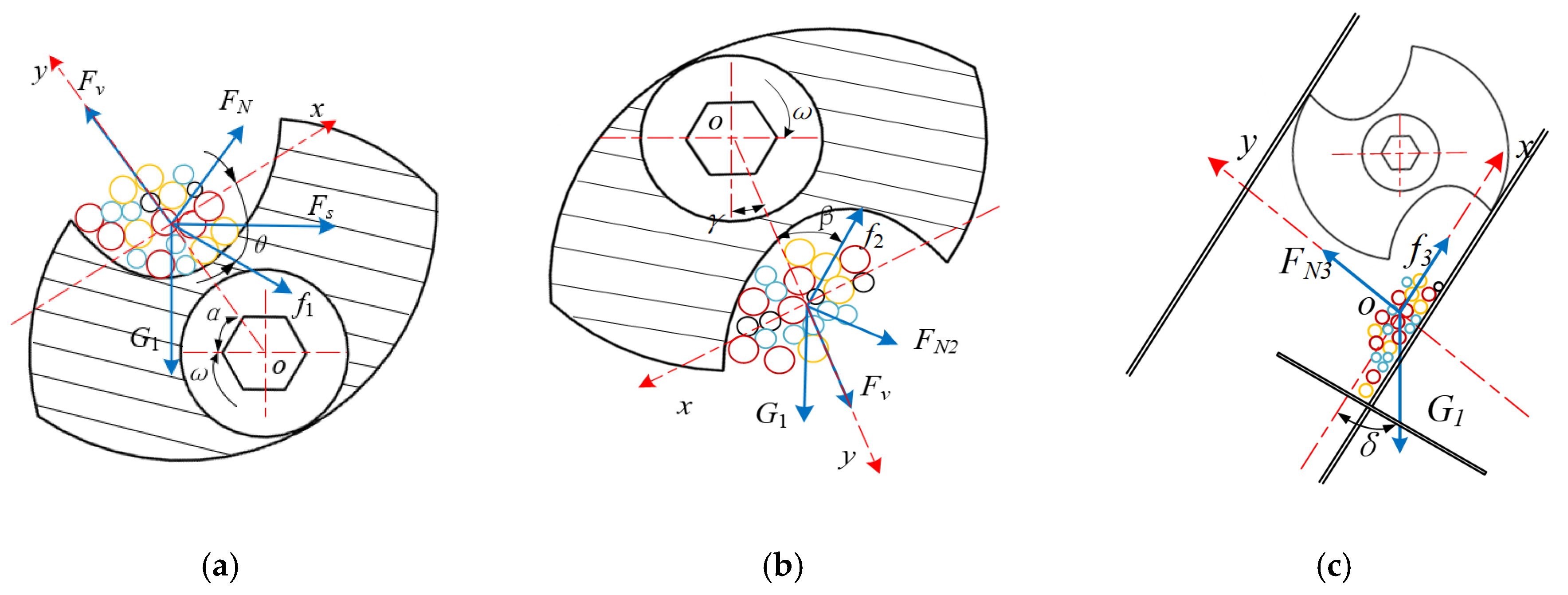
2.2.4. Mechanical Analysis of the Fertilization Process

The fertilizer filling performance affects the fertilizer application performance of strip-hole layering, so it is particularly important to analyze the fertilizer filling process. In the process of fertilizer filling, assuming that the fertilizer is a rigid body of uniform material, without considering the vibration and friction between the particles, the fertilizer particles in the typed hole are considered as a whole, with the center of mass of the fertilizer group as the origin, and the normal and tangential directions of the motion of the fertilizer group center of mass system established as shown in Figure 5 for the auxiliary coordinate system.
Based on the forces on the fertilizer granules in the typed hole, the force equation is established as follows
{ F N sin θ + F s sin α + f 1 cos θ = G 1 cos α F v + F N cos θ G 1 sin α + f 1 sin θ + F s cos α f 1 = μ F N G 1 = m g F v = m ω 2 R ω = π n 30
where FN is the support of fertilizer clusters by the inner wall of the profiled hole (N); FS is the lateral forces on the inner wall of the type hole against the fertilizer group (N); f1 is the friction of the inner wall of the profiled hole against the fertilizer group (N); G1 is the fertilizer group gravity (N); Fv is the inertial centrifugal force (N); μ is the coefficient of friction between the contact surface of the fertilizer and the type-hole wheel; m is the fertilizer group quantity (kg); θ is the taper angle of the profiled hole (°); ω is the angular speed of profile wheel (rad/s); R is the radius of the type hole wheel (mm); n is the operating speed of type hole wheel (r/min); g is the gravitational acceleration (m/s2).
According to Equation (3) it yields
α arccos e 1 g 1 + μ 2 arctan ω 2 R e 1 e 2
where e1 = cosθμsinθ, e2 = μcosθ + sinθ. From Equation (4) it follows that the starting filling angle α, which affects the filling performance, is related to the angular speed ω of the type hole wheel, the radius R of the type hole wheel, the cone angle θ of the wheel, and the material characteristics μ of the fertilizer and wheel. When the angular velocity of the type hole wheel is determined, the starting fertilizer filling angle α and the typed hole cone angle θ are inversely proportional; when the starting fertilizer filling angle α is the same, the typed hole cone angle θ and the typed hole wheel angular velocity ω are positively correlated. To meet the fertilizer granules in the fertilizer filling typed hole wheel 6.67–20 r/min can be filled into the typed hole, and at the same time to ensure that the fertilizer can be better filled into the type hole when the fertilizer filling area is less, the starting fertilizer filling angle α should be less than or equal to the natural rest angle α ≤ 35° and the cone angle θ of the typed hole can be calculated as 8.02–50.42°.

2.2.5. Mechanical Analysis of the Fertilizer Unloading Process

In the process of fertilizer discharge, the fertilizer particles in the typed hole are discharged along with the axial and radial directions of the filling chamber under the action of gravity and centrifugal force; the time interval between the first and last fertilizer particles discharged in a hole has a direct impact on the hole formation, a larger time interval results in a longer distribution of hole length, worse hole formation performance, a lower uptake rate of maize roots and an altered fertilizer utilization rate. To improve the utilization efficiency of the fertilizer, the time interval between the exclusion of fertilizer particles in the same type hole should be reduced, and the force analysis of the fertilizer group in the process of fertilizer discharge is shown in Figure 5b.
{ G 1 sin γ = f 2 sin β + F N 2 cos β G 1 cos γ + F v + F N 2 sin β = f 2 cos β f 2 = μ F N 2
where FN2 is the support of fertilizer clusters by the sidewalls of the profile holes (N); f2 is the friction between fertilizer granules and the sidewalls of the typed hole (N); γ is the angle of discharge of fertilizer (°); β is the angle of unloading fertilizer (°).
From Equation (5) we can obtain
γ = arccos j 1 G 1 j 1 2 + j 2 2 + arcsin F v j 2 j 1 2 + j 2 2
where j1 = μsinβ + cosβ, j2 = μcosβ − sinβ. Based on the physical properties of the fertilizer, and the speed of the fertilizer filling type hole wheel of 6.67–20 r/min, and for ease of calculation, as well as ease of processing, the angle β at which the AUF was selected to be 50–70°. To determine the installation angle of the fertilizer tube, mechanical analysis of the fertilizer granules after they have been dislodged from the typed hole was carried out, the mechanical analysis is shown in Figure 5c.
{ F a = G 1 cos δ f 3 F N 3 = G 1 sin δ f 3 = μ 1 F N 3
where, Fa is the combined forces on fertilizer groups (N); FN3 is the fertilizer granules supported by the tube wall (N); f3 is the fertilizer granules subjected to friction by the tube wall (N); δ is the Angle of fertilizer tube installation; μ1 is the friction factor of fertilizer granules against the tube wall.
According to Equation (7) we obtain
F a = G 1 ( cos δ μ 1 sin δ )
where the range of values of δ is 30–40°, it can be seen from Equation (8) that the combined force Fa on fertilizer particles after leaving the typed hole decreases with the increase of δ; therefore, the AFT affects the movement of fertilizer particles and the proportion of fertilizer applied to each layer, which affects the speed of fertilizer particles falling into the fertilizer sheet. The fertilizer particles are mainly subject to the action of gravity G1 at the moment they leave the fertilizer application opening, and their trajectory is approximated by the free-falling motion with initial velocity v. Different initial velocities will distribute the fertilizer particles into different holes, which in turn affects the effect of the precision strip-hole layered fertilization subsoiler application operation.

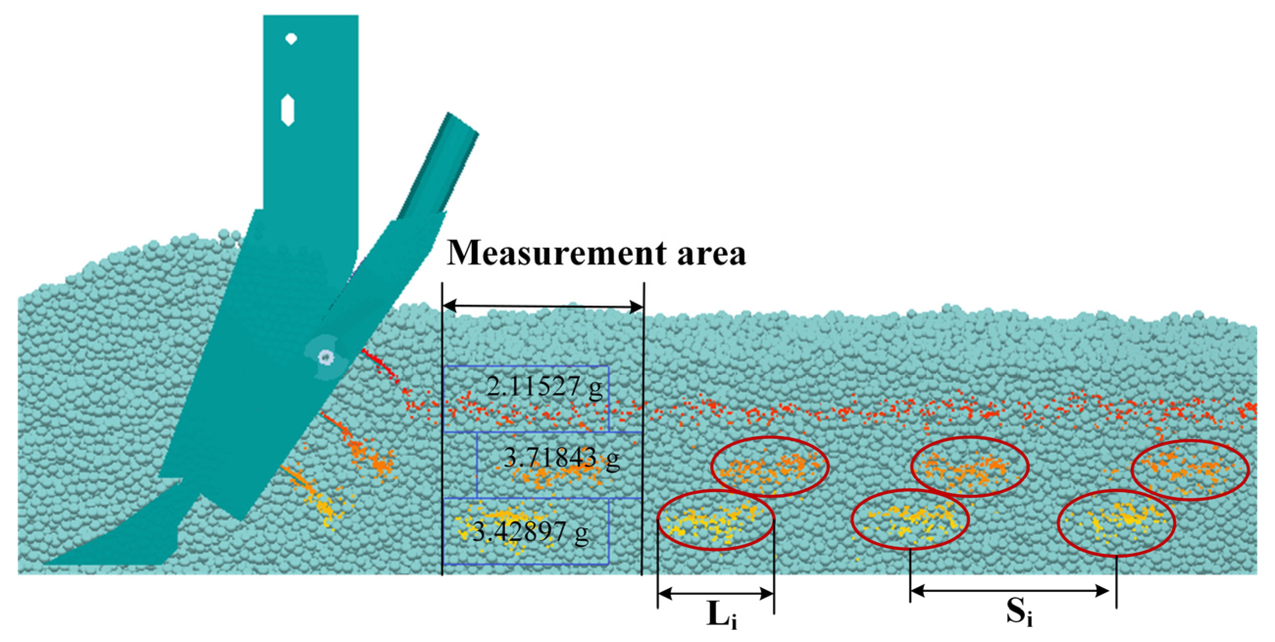
2.3. Simulation Model Building

Based on the aforementioned research, to verify the operational effectiveness of the designed precision strip-hole layered fertilization subsoiler, a simulation of the fertilizer application process was carried out using discrete element analysis software to establish soil particles and fertilizer particles, and to discuss the effects of machine forward speed, AUF and AFT on the hole formation performance and fertilizer application stability.
The 3D modeling software was used to build a model of the deep pine strip cavity application layered fertilizer application device into step format, which was imported into the discrete element software EDEM. The Hertz–Mindlin (no-slip) contact mechanics model was chosen as the inter-particle contact model. Many scholars [29,30] have shown that the soil model can be replaced by equivalent spherical particles with a radius of 6 mm, which can simulate the interaction between the soil and the subsoiler very well; the fertilizer particles are mainly spherical in shape, and their spherical rate is above 90%, which can be considered as spherical with an equivalent particle size of 3 mm. The parameters of the soil particles, fertilizer particles and a strip-hole layered fertilization subsoiler variables are shown in Table 1 [31,32]. Some structures that do not affect the analytical performance were simplified and the simulation model is shown in Figure 6.

2.4. Experimental Design and Evaluation Methods

Based on the aforementioned analysis, a single-factor test was carried out to obtain the optimum AFT, with a forward speed of 2 km/h and the AUF at 60°, to test the influence of the five types of AFT on the FADSC in the upper, middle and lower layers. To obtain a better combination of working parameters, a three-factor test was carried out on the machine speed, the AUF, the fertilizer and the AFT, with the machine speed set at three levels of 1, 2 and 3 km/h, the AUF and the fertilizer were set at three levels of 50°, 60° and 70° and the AFT was set at three levels of 30°, 35° and 40°. The test was carried out with the FDT and FADSC in the middle and lower layers as performance evaluation indicators.
We added the Grid Bin Group to the EDEM post-processing interface after the simulation test was completed, and selected 10 randomly selected areas of 25 mm in length in the experimental stability zone of the single-factor impact test. We recorded the mass of the fertilizer in the upper layer of the Grid Bin Group, and the mass of fertilizer in the middle and lower layers below it in the same way; we calculated the stability coefficient of deviation of fertilizer application volume in the three layers under different treatments, and calculated the formula as
η = 1 n i = 1 n ( m i m 0 ) 2 m 0 × 100 %
where η is the fertilization amount deviation stability coefficient (%); mi is the actual amount of fertilizer applied (g); m0 is the standard fertilizer application rate (g); n is the number of measurements.
In a three-factor test, RULER was added to the EDEM post-treatment interface to measure the FDT in the middle and lower layers. Fertilizer granule data were collected in the calculation domain each time and the FDT in the middle and lower layers were calculated for the different treatments. The formula is calculated as
L = i = 1 n L i n
where L is the average fertilizer distribution length (mm).

3. Results

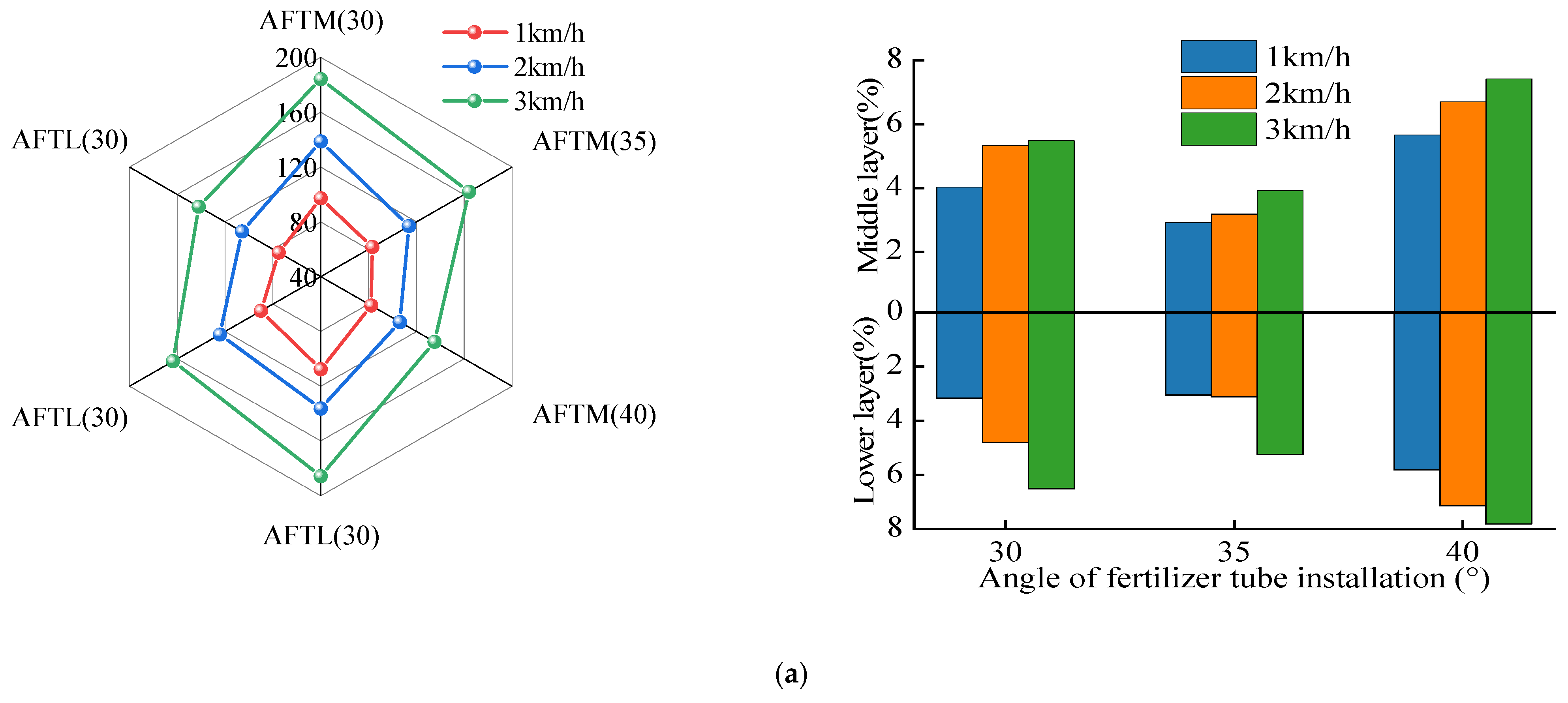
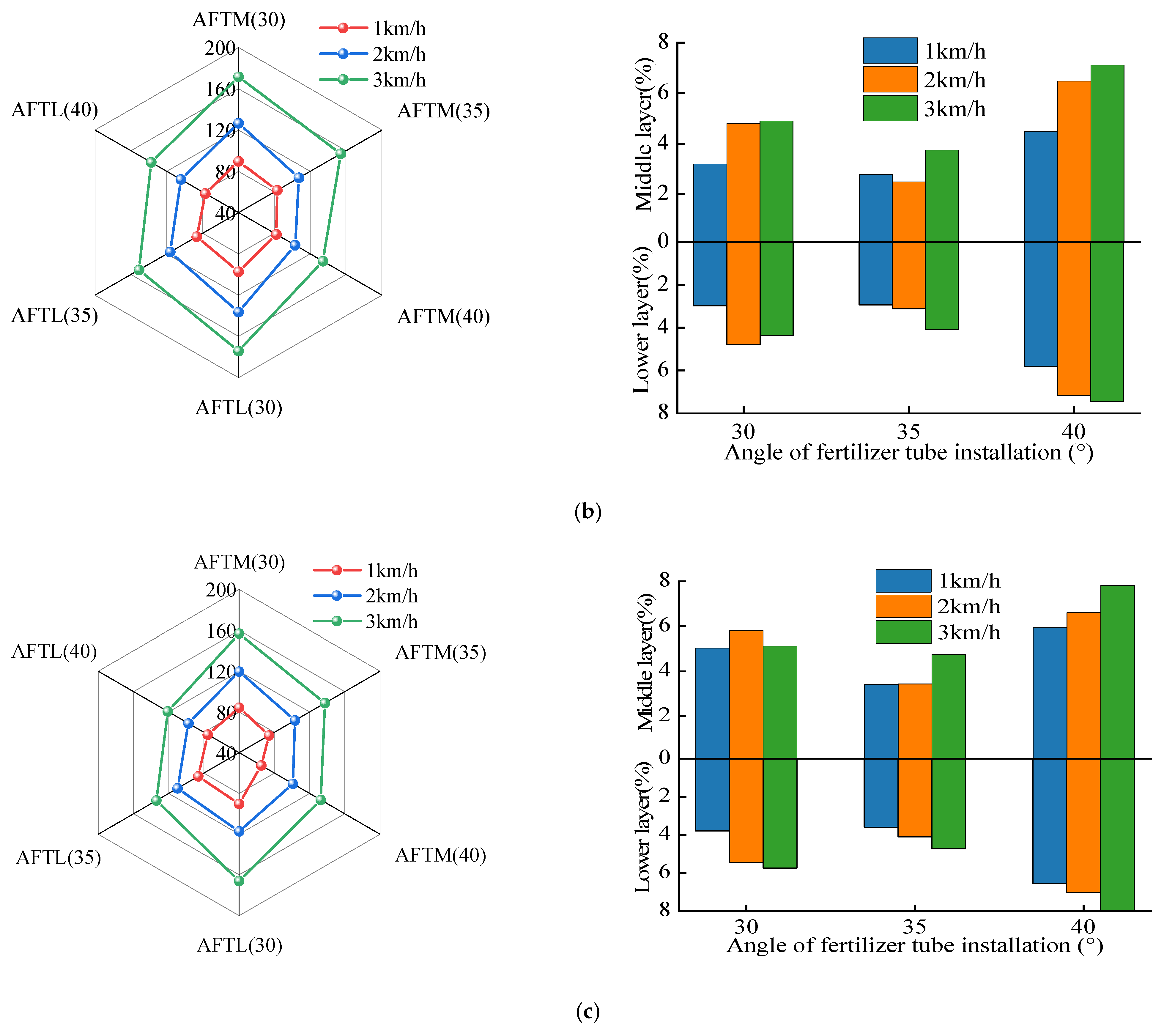
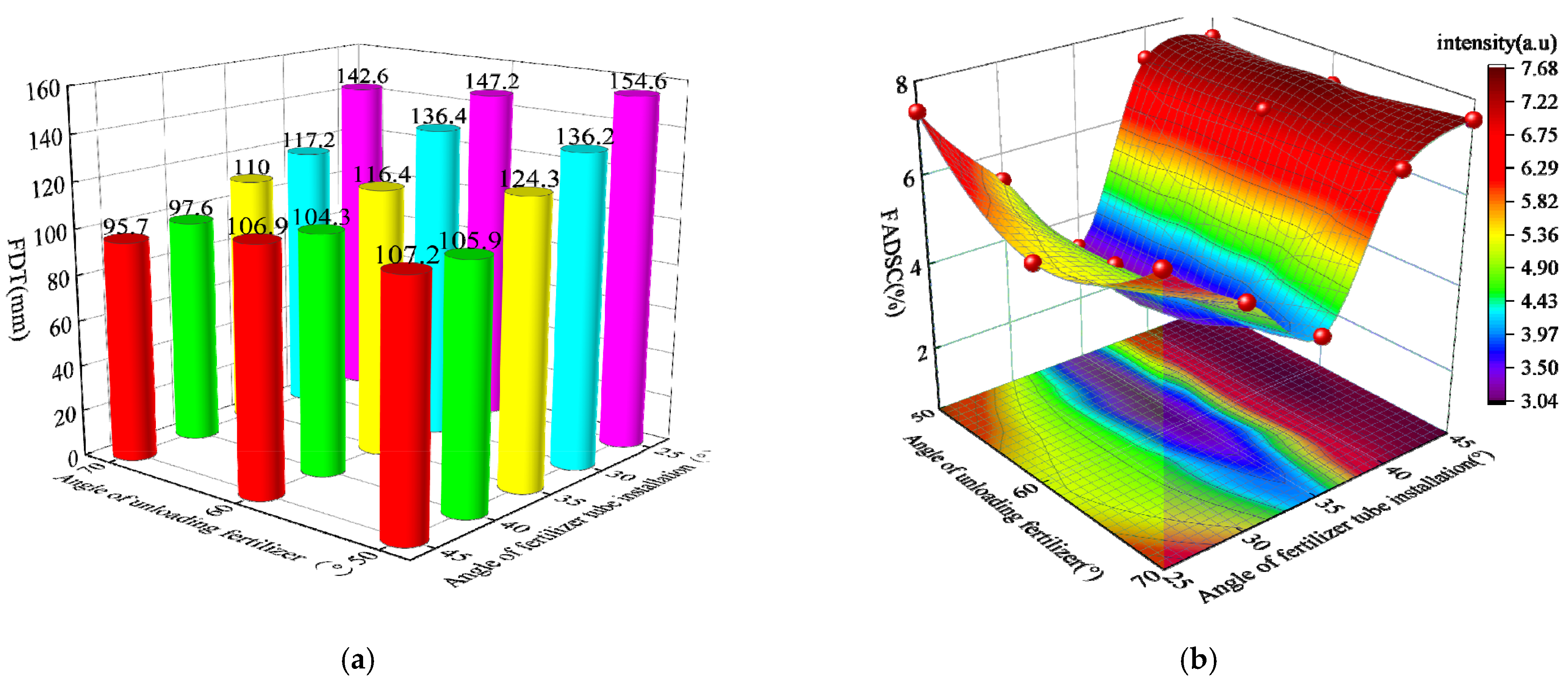
3.1. Effect of Factors on the Effectiveness of Fertilizer Application

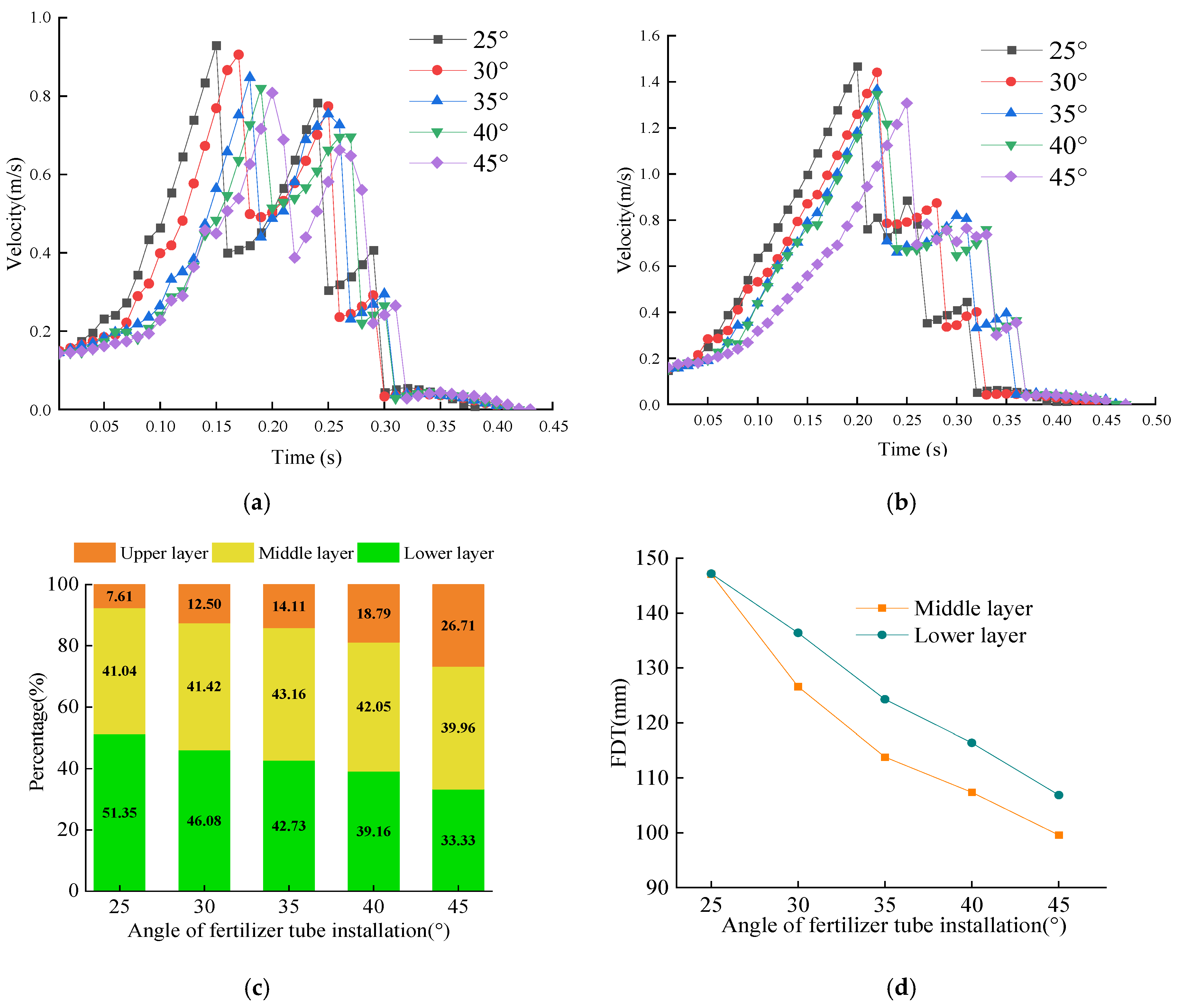
3.1.1. The Effect of the AFT on the Fertilization Effect

To investigate the influence of the AFT on the application ratio and the FDT, the fertilizer pellet was selected from each of the fertilizers falling into the middle and lower layers and its motion characteristics were analyzed as shown in Figure 7a. The fertilizer pellet accelerated under the action of gravity after leaving the fertilizer type hole wheel, the fertilizer pellet AFT at 25° was the first to reach the opening; the time required to reach the middle layer discharge opening was 0.15 s and the lower layer discharge opening was 0.20 s, AFT at 45°, the fertilizer pellet was the last to reach the discharge opening and the time required to reach the middle layer discharge opening was 0.21 s and the lower layer discharge opening was 0.25 s. The smaller the AFT, the greater the acceleration of the fertilizer particles, the greater the speed of the fertilizer particles arriving at the discharge opening first and reaching the opening, and the greater the speed loss caused by the collision between the fertilizer particles at the opening and the fertilizer application sheet, but the greater the speed of the fertilizer particles arriving at the opening, the greater the speed after ejection and the less time spent on the fertilizer application sheet is discharged from the fertilizer tube. Compared with Figure 7b, it can be seen that the speed of fertilizer particles falling into the lower discharge opening is greater than the speed of the middle discharge opening, and the time difference between the lower layer of the different AFT when the fertilizer particles fall into the soil is greater than the time difference in the middle layer, which will result in a greater difference in the FDT than the FDT for different fertilizer tube installation angles.
The effect of different AFT on the proportion of fertilizer applied to each layer is shown in Figure 7c. The average mass of fertilizer applied to the upper, middle and lower layers was obtained by post-processing, the proportion of fertilizer applied to the upper layer increased with increasing AFT, and the proportion of fertilizer applied to the upper layer increased from 7.61% to 26.71%, the proportion of fertilizer applied to the middle layer did not change much with the effect of AFT, the proportion of fertilizer applied to the lower layer decreased with increasing AFT, the proportion of fertilizer applied to the lower layer increased from 51.35% decreasing to 33.33%; The effect of FDT on the middle and lower layers with AFT is shown in Figure 7d. The FDT length of the middle and lower layers decreases with increasing AFT. This means that increasing the AFT can reduce the speed of the fertilizer particles coming out of the discharge opening and thus reduce the FDT, but it will lead to an increase in the proportion of fertilizer applied to the upper layer and an increase in the gap between the middle and lower layers. In order to ensure that the fertilizer ratio between the middle and lower layers meets the growth pattern of maize [20], the AFT was determined to be 30–40°.

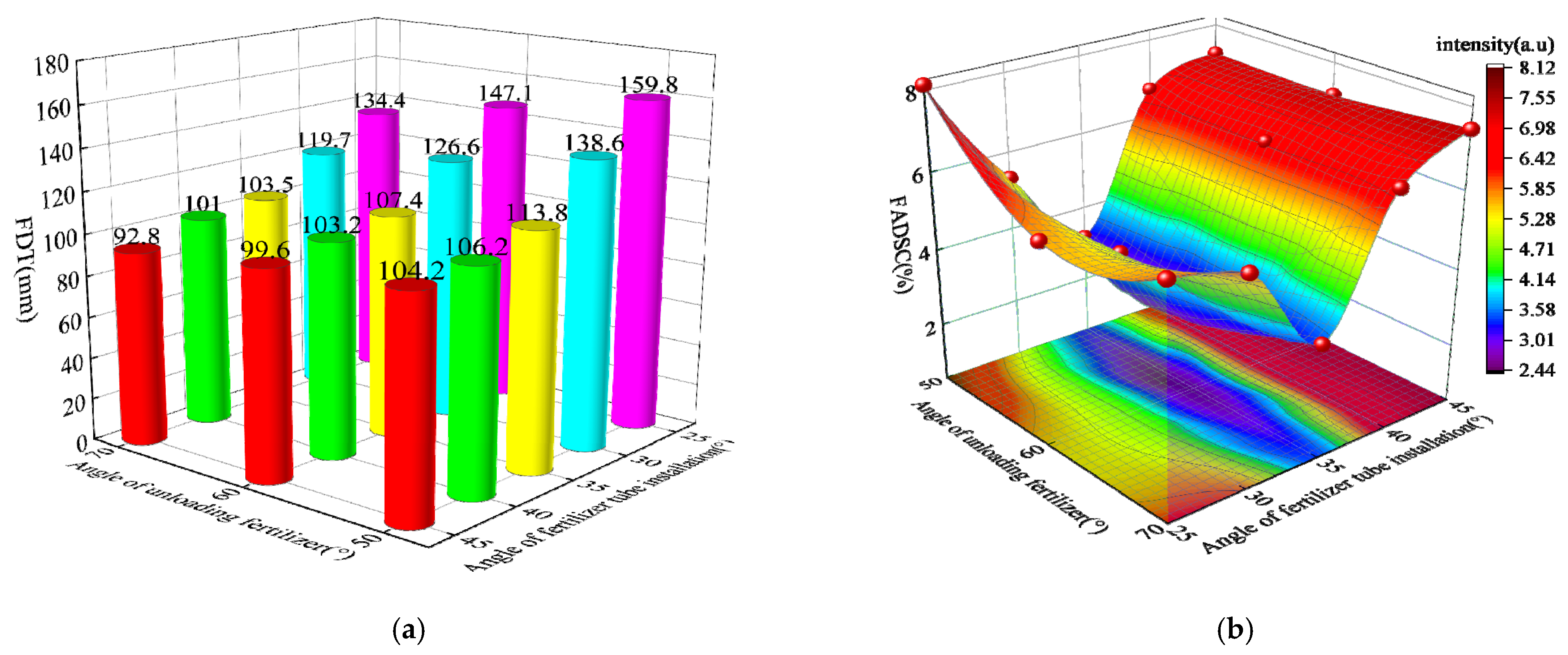
3.1.2. Effect of Factors on Cavity Formation Performance
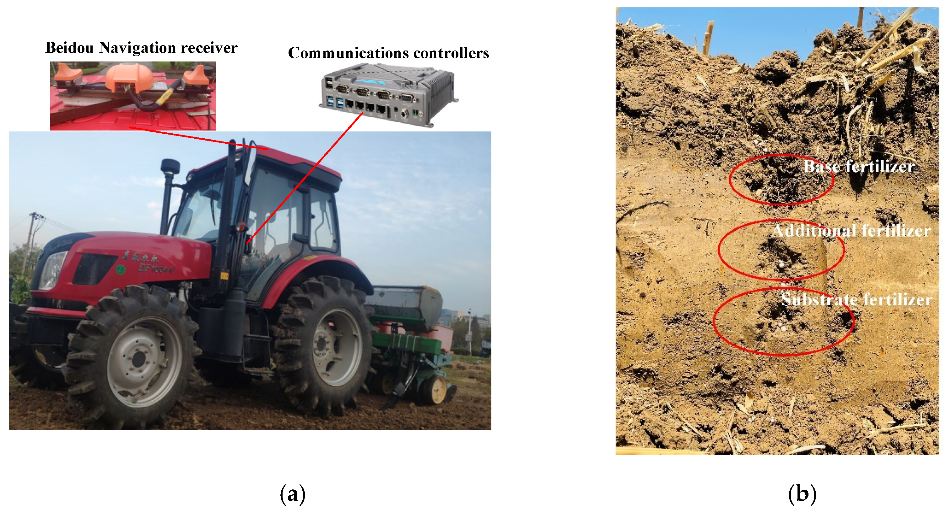
Using the middle and lower layers of the FDT and the FADSC as evaluation indicators, the test results with their factor levels are displayed in Table 2.
The degree of dispersion of fertilizer particles after landing decreases with increasing AUF at a forward speed of 1–3 km/h, indicating that at a certain amount of fertilizer applied per hole, the larger the AUF, the larger the hole width and the smaller the hole depth, the smaller the degree of dispersion of fertilizer particles after landing, and the shorter the hole length; FADSC decreases and then increases with increasing AUF.
To analyze the influence of forwarding speed and AUF on the cavity formation performance, the influence curves of different forward speeding and AUF on the middle layer (AUFM) and lower layer (AUFL) of the FDT and the FADSC were plotted with an AFT of 30°, 35° and 40°, and the influence curves are shown in Figure 8.
Figure 8 shows that when the AFT is at a certain angle, the FDT increases with the forward speed and the FADSC of the hole fertilizer quantity basically increases with the forward speed, because the increase of the forward speed increases the rotational speed of the fertilizer hole wheel, which causes the fertilizer particles to obtain a larger initial velocity when leaving the hole, thus making the initial velocity of the fertilizer particles larger when leaving the discharge opening for free fall movement while unloading the fertilizer. When AUF is certain, the difference between the middle and lower layers of the FDT at the same speed is not great, because the time spacing between the fertilizer particles being discharged from the upper and lower discharge ports are basically equal, and the lower layer fertilizer particles are accelerated in the fertilizer application tube; when the AUF is 50°, the width of the typed hole wheel is small and the depth is large, which makes the fertilizer particles stay in the typed hole for a long time, resulting in the hole being discharged at a large time spacing, resulting in a large FDT. When the AUF is 70°, the large width and small depth of the wheel make the fertilizer particles stay in the holes for a long time, resulting in a small FDT.
Analysis of the effect of advance velocity and AFT on hole formation performance, the curves of the influence of different forward speeds and different AFT of the middle layer (AFTM) and lower layer (AFTL) of the FDT and the AUF were plotted at 50°, 60° and 70° of the AUF, and the influence curves are shown in Figure 9.
The FDT increases with the forward speed when the AUF is certain, and the FADSC basically increases with the forward speed in Figure 9; the FDT decreases with the AFT because the increase of the AFT will increase the gravitational force of the fertilizer particles along the slope, thus increasing the initial velocity of the fertilizer particles when they are discharged from the discharge opening, thus increasing the degree of dispersion of the fertilizer particles. The above graphs show that the stability coefficient of the cavity fertilizer application deviation increases and then decreases as the AFT increases deviations at low speeds and is not significantly affected by speed.
To analyze the interaction between the AUF and the AFT on the hole formation performance, under the condition of meeting the requirement of hole spacing, the forward speed was selected as 2 km/h to draw the relationship diagram of the influence of the AUF and the AFT on the middle and lower layers of the FDT and the FADSC.
Figure 10a shows that at a forward speed of 2 km/h, the FDT is minimized when the AFT is at a low angle and the angle of the AUF is at a high level. At a certain value of the AUF, the FDT decreases with the AFT increasing; at a certain value of the AFT, the FDT decreases with the AUF increasing, and the AFT has a greater effect on the FDT than the AUF has on the FDT. As can be seen from Figure 10b above, when the AFT is medium level, and when the AUF is medium level, at a certain value of the AUF, the FADSC decreases and then increases with increasing AFT; at a certain value of the AFT, the FADSC decreases with increasing the AUF, the AFT has a greater influence on the FADSC than the AUF has on the FADSC.
It can be seen from Figure 11a above, at a forward speed of 2 km/h, the FDT is minimized when the AFT is at a low level and the AUF is at a high level. At a certain AUF, the FDT decreases with increasing the AFT; at a certain AFT, the FDT decreases when increasing the AUF, and the effect of the AFT on the FDT is greater than the effect of the AUF on the FDT. Figure 11b shows when the AFT is medium level, and when the AUF is medium level. when the AUF is certain, the FADSC decreases and then increases with the increase of the AFT; when the AFT is certain, the FADSC decreases with the increase of the AUF, and the influence of the AFT on the FADSC is larger than the influence of the AUF on the FADSC.
To sum up, at a forward speed of 1–3 km/h, the FDT increases with increasing forward speed and the FADSC increases with increasing forward speed. Under the requirement of the FDT and the FADSC, the forward speed of 2 km/h was selected for parameter optimization, and the optimal parameters were obtained as follows: the AUF was 60°, the AFT was 35°, corresponding middle and lower layers of the FDT were 107.4 mm and 116.3 mm, and corresponding middle and lower layers of the FADSC were 2.49% and 2.93%.

3.2. Field Test

To further verify the reliability of the designed strip-hole layered fertilizer subsoiler, the optimal parameters obtained through simulation tests were used to process the deep pine strip-hole layered fertilizer application device, which was carried out at the experimental site of Anhui Agricultural University Northwest Anhui Experimental Station, Yangqiao Town, Fuyang City, Anhui Province, with the test component mounted on a no-till planter, as shown in Figure 12a, powered by a DF1004-6 tractor of Dongfeng Agricultural Machinery. The basic physical characteristics of the soil were measured and the average moisture content was 20.74%.
The test was carried out at a forward speed of 2 km/h. As the fertilizer was difficult to collect in the soil, this test was carried out by taking a dissected section of the soil after the fertilizer application operation was completed, removing the fertilizer and soil, screening out the fertilizer and soil, then weighing the fertilizer and calculating the FADSC, as shown in Figure 12b, for the soil section after the fertilizer application operation.
The FADSC in the middle and lower layers were 11.36% and 12.42%, respectively, and the relative errors between the test and simulation values were 8.87% and 9.49%, respectively. The main reason for the analysis was that in the actual operation, the field soil environment was more complex and unstable compared to the simulation test, and factors, such as small soil clods and weed roots in the soil caused the difference between the field test and the simulated test results to not be significant and within the permissible range of the test.

4. Discussion

In precision strip-hole layered fertilization, as can be seen in Section 3, when the forward speed is 1 km/h, the average FDT and FADSC in the middle of this unit is 82.30 mm, and the average FDT in the lower layer is 87.31 mm. At a forward speed of 2 km/h, the average FDT in the middle layer increased to 113.33 mm and in the lower layer to 116.4 mm. At the maximum forward speed of 3 km/h, the average FDT in the middle layer reached 152.28 mm, and the average FDT in the lower layer reached 152.77 mm. From the above, it can be seen that as the forward speed increases, the FDT also increases, the main reason is that the fertilizer particles from the type of hole after the drop to the discharge port mainly rely on gravity. The greater the forward speed, and a farther lateral distance, will lead to an increase in the hole length, while a lower FDT than an upper FDT is larger. The fertilizer particles in the drop fertilizer port are greater than the upper drop fertilizer port and the distance between the type hole; increasing the fertilizer particles in the fertilizer application tube movement time will increase the FDT. In subsequent studies, it is possible to add a pneumatic assist function to reduce the time for the fertilizer to travel from the fertilizer application type orifice wheel to the discharge port, increasing the working speed during the discharge feeding process, and reducing the FDT.
In this paper, the minimum FADSC of 2.49% is obtained when the forward speed is 2 km/h, AUF is 60° and AFT is 35°; the maximum FADSC of 8.03% is obtained when the forward speed is 3 km/h, AUF is 70° and AFT is 40°, meanwhile, observing Table 2, we can ascertain that the larger the forward speed is, the larger the FADSC is, and the minimum FADSC is obtained when AUF is 60°. The reason is that the faster the forward speed is, the larger the angular speed of the type-hole wheel is, which will make the fertilizer filling insufficient and increase the FADSC, and when the AUF and AFT are in the middle value, it will make the type-hole wheel filling sufficient and unloading complete, which will reduce the FADSC. Under the basic premise of satisfying the FDT, the FADSC was chosen as the evaluation index because the uniformity of fertilizer application is one of the most important indicators to evaluate the performance of fertilizer application machinery in the process of fertilizer application machinery, and the uniformity of fertilizer application volume in the same soil layer will affect the growth of maize which, in turn, affects the yield of maize in the later stages.
Maize is a fertilizer-loving crop, and deep tillage strip-hole layered fertilization helps the growth of the maize root system. The middle layer of hole fertilization is next to the maize root system because the maize root system is weak when the maize is at the pulling stage, and fertilizer particles too close to the maize will cause the burning of the seedlings, and the lower layer of hole fertilization is directly below the maize root system to help the maize absorption during the filling stage. At the same time, the deep application of fertilizer will promote the growth of maize roots, making the N content of the lower soil well absorbed by the maize. The N content of the fertilizer in the deep soil will increase the utilization of elemental N, which will then greatly improve the utilization efficiency of the fertilizer [33].

5. Conclusions

(1)
The precision strip-hole layered fertilizer subsoiler was designed, which can apply fertilizer to the soil in quantitative and fixed positions according to the fertilizer requirements of the maize growth cycle and the length of the root system in each period, facilitating the absorption of fertilizer nutrients by the maize; the subsoiler can deeply loosen the lower layer of soil, helping to reduce soil erosion, increase the water storage capacity of the soil, improve the growth environment of the maize root system and facilitate the growth and development of the maize root system and the full absorption of fertilizer nutrients.
(2)
In the determination of the size of the type of hole wheel by theoretical analysis and para-metric calculation of the type hole wheel, the main factors influencing the effectiveness of the application of fertilizer in the strip-hole stratification unit are the AUF, the AFT and the forward speed. At a forward speed of 2 km/h, AUF at 60° and AFT at 35°, the simulation yielded a minimum FADSC of 2.49% and 2.93% for the middle and lower layers of FADSC, respectively. The field trials yielded were 11.36% and 12.43% for the middle and lower layers of FADSC, which met the fertilizer application criteria of the cavity applicator.
(3)
In summary, the idea of the stratified strip-hole application was essential to meet the demand for fertilizer at all times of maize growth, while using strip hole fertilization in the middle and lower layers can reduce fertilizer consumption and improve fertilizer utilization efficiency, which has a positive effect on environmental protection. The idea also can provide a new concept for precision fertilization machines.

Author Contributions

Conceptualization, W.W.; methodology, W.W.; software, J.S.; validation, J.S.; formal analysis, G.Z.; investigation, G.Z.; resources, J.S.; data curation, J.S.; writing—original draft preparation, J.S.; writing—review and editing, W.W.; visualization, L.Q. and C.Z.; supervision, L.C.; project administration, W.W.; funding acquisition, L.C. and W.W. All authors have read and agreed to the published version of the manuscript.

Funding

This work was Supported by National Natural Science Foundation of China (NO. 52005008), Anhui University Cooperation Collaborative Research Project (NO. GXXT-2020-011), Natural Science Foundation of Anhui Province (NO. 2008085QE217, 1908085MC91) and the Natural Science Research Project of Higher Education Institutions (NO. KJ2021A0158).

Institutional Review Board Statement

Not applicable.

Informed Consent Statement

Not applicable.

Data Availability Statement

The data used in this study is self-test and self-collection. Because the control method designed in this paper is still being further improved, Data cannot be shared at present.

Conflicts of Interest

The authors declare no conflict of interest.

References

  1. Wang, W.W.; Wu, K.P.; Zhang, Y.; Wang, M.X.; Zhang, C.L.; Chen, L.Q. The Development of an Electric-Driven Control System for a High-Speed Precision Planter Based on the Double Closed-Loop Fuzzy PID Algorithm. Agronomy 2022, 12, 945. [Google Scholar] [CrossRef]
  2. Wang, L.Y. Study on the comparative advantages of major food crops in China. Rural Econ. Technol. 2020, 31, 19–20. [Google Scholar]
  3. Wan, L.; Xie, D.B.; Li, Y.; Chen, L.Q. Design and experiments of a roller type hole application and fertilizer row dispenser for maize. J. Agric. Mach. 2020, 51, 64–73. [Google Scholar]
  4. Rotundo, J.L.; Rech, R.; Cardoso, M.M.; Fang, Y.; Tang, T.; Olson, N.; Pyrik, B.; Conrad, G.; Borras, L.; Mihura, E.; et al. Development of a decision-making application for optimum soybean and maize fertilization strategies in Mato Grosso. Comput. Electron. Agric. 2022, 193, 106659. [Google Scholar] [CrossRef]
  5. Basso, B.; Sartori, L.; Cammarano, D.; Fiorentino, C.; Grace, P.R.; Fountas, S.; Sorensen, C.A. Environmental and economic evaluation of N fertilizer rates in a maize crop in Italy: A spatial and temporal analysis using crop models. Biosyst. Eng. 2012, 113, 103–111. [Google Scholar] [CrossRef]
  6. Zhou, B.Y.; Sun, X.F.; Ding, Z.S.; Ma, W.; Zhao, M. Effects of soil tillage and fertilizer application on dry matter accumulation and yield of summer maize. Chin. Agric. Sci. 2017, 50, 2129–2140. [Google Scholar]
  7. Yang, Q.L.; Huang, X.Y.; Wang, Q.J.; Li, H.W.; Wang, Y.B.; Wang, L.Y. Structural optimization and experimentation of a spatially layered fertilizer application unit for maize. J. Agric. Mach. 2020, 51, 175–185. [Google Scholar]
  8. Yu, C.Y.; Liu, J.; Yin, J.N.; Bi, L.L.; Zhang, S.; Zhou, H.Y.; Zhu, D.Q. Design and optimization and experimental verification of a segmented double-helix blade roller for straw returning cultivators. J. Chin. Inst. Eng. 2021, 44, 379–387. [Google Scholar] [CrossRef]
  9. Chen, Z.Y.; Duan, W.W.; Wang, G.Y.; Li, B.; Chen, Z.P. Effects of slow-release fertilizer application methods on population growth and yield of summer maize. Jiangsu Agric. Sci. 2021, 49, 92–96. [Google Scholar]
  10. Wyngaard, N.; Echeverría, H.E.; Rozas, H.R.; Divito, G.A. Fertilization and tillage effects on soil properties and maize yield in a Southern Pampas Argiudoll. Soil Tillage Res. 2012, 119, 22–30. [Google Scholar] [CrossRef]
  11. Huang, X.; Wang, W.W.; Li, Z.D.; Wang, Q.Q.; Zhu, C.X.; Chen, L.Q. Design method and experiment of machinery for combination of seed fertilizer and herbicide. Int. J. Agric. Biol. Eng. 2019, 12, 63–71. [Google Scholar]
  12. Lou, S.Y.; He, J.; Li, H.W.; Wang, Q.J.; Lu, C.Y.; Liu, W.Z.; Liu, P.; Zhang, Z.G.; Li, H. Current Knowledge and Future Directions for Improving Subsoiling Quality and Reducing Energy Consumption in Conservation Fields. Agriculture 2021, 11, 575. [Google Scholar] [CrossRef]
  13. Hamza, M.A.; Anderson, W.K. Soil compaction in cropping systems: A review of the nature, causes and possible solutions. Soil Tillage Res. 2005, 82, 121–145. [Google Scholar] [CrossRef]
  14. Zhao, Y.Z.; Wang, Y.; Gong, Z.P.; Yang, Y.Q.; Zhao, S.H.; Gou, J.B. Design and test of no-till planter side deep layered fertilizer application seeding components. J. Agric. Mach. 2021, 52, 40–50. [Google Scholar]
  15. Zhai, L.; Xu, P.; Zhang, Z.; Li, S.; Xie, R.; Zhai, L.; Wei, B. Effects of deep vertical rotary tillage on dry matter accumulation and grain yield of summer maize in the Huang-Huai-Hai Plain of China. Soil Tillage Res. 2017, 170, 167–174. [Google Scholar] [CrossRef]
  16. da Silva, R.F.; da Costa Severiano, E.; de Oliveira, G.C.; Barbosa, S.M.; Peixoto, D.S.; Tassinari, D.; Silva, B.M.; Silva, S.H.G.; Júnior, M.D.S.D.; Figueiredo, T.D.A.F.R. Changes in soil profile hydraulic properties and porosity as affected by deep tillage soil preparation and Brachiaria grass intercropping in a recent coffee plantation on a naturally dense Inceptisol. Soil Tillage Res. 2021, 213, 105127. [Google Scholar] [CrossRef]
  17. Scanlan, C.A.; Davies, S.L. Soil mixing and redistribution by strategic deep tillage in a sandy soil. Soil Tillage Res. 2019, 185, 139–145. [Google Scholar] [CrossRef]
  18. Schneider, F.; Don, A.; Hennings, I.; Schmittmann, O.; Seidel, S.J. The effect of deep tillage on crop yield—What do we really know? Soil Tillage Res. 2017, 174, 193–204. [Google Scholar] [CrossRef]
  19. Quan, L.Z.; Feng, H.Q.; Lv, Y.J.; Wang, Q.; Yuan, Z.Y. Maize seedling detection under different growth stages and complex field environments based on an improved Faster R–CNN. Biosyst. Eng. 2019, 184, 1–23. [Google Scholar] [CrossRef]
  20. Wang, Y.X.; Liang, Z.J.; Cui, T.; Zhang, D.X.; Qu, Z.; Yang, L. Structural design and experiment of maize layered fertilizer applicator. J. Agric. Mach. 2016, 47, 163–169. [Google Scholar]
  21. Yang, R.B.; Yang, H.G.; Lian, Z.G.; Zhang, X.; Guo, D.; Zheng, Y.Y. Design and experiment of a layered fertilizer opener for potato planters. J. Agric. Mach. 2018, 49, 104–113. [Google Scholar]
  22. Yang, X.L.; Zhao, H.; Yang, R.B.; Wu, X.F.; Wang, Z.Z. Design and hydrostatic simulation of a layered fertilizer opener for potato planters. Agric. Eng. 2019, 9, 81–84. [Google Scholar]
  23. Qian, F.F. Design and Experiment of Maize Hole Fertilizer Applicator; Anhui Agricultural University: Hefei, China, 2016. [Google Scholar]
  24. Wu, R.R.; Zhang, L.Y.; Qian, F.F.; Cai, H.T. Design and simulation of maize hole fertilizer application device. J. Anhui Agric. Univ. 2017, 44, 941–946. [Google Scholar]
  25. Zhang, J.X.; Liu, H.M.; Gao, J.; Lin, Z.H.; Chen, Y. Simulation and experiments of SPH of a layered orthotropic hole fertilizer precision sowing machine for maize. J. Agric. Mach. 2018, 49, 66–72. [Google Scholar]
  26. Liu, Z.D.; Wang, Q.J.; Liu, C.G.; Li, H.W.; He, J.; Liu, J.X. Design and experiments of a cavity-disk type precision cavity fertilizer application device. J. Agric. Mach. 2018, 49, 137–144. [Google Scholar]
  27. Wang, Q.Q.; Li, Z.D.; Wang, W.W.; Zhang, C.L.; Chen, L.Q.; Wan, L. Multi-objective optimization design of wheat centralized seed feeding device based on particle swarm optimization (PSO) algorithm. Int. J. Agric. Biol. Eng. 2020, 13, 76–84. [Google Scholar] [CrossRef]
  28. Yang, Q.L.; Wang, Q.J.; Li, H.W.; He, J.; Lu, C.Y.; Yu, C.C.; Lou, S.Y.; Wang, Y.B. Development of a layered fertilizer application adjustment device for pneumatic collector-discharge variable fertilizer system. J. Agric. Eng. 2020, 36, 1–10. [Google Scholar]
  29. Wang, X.; Zhang, S.; Pan, H.; Zheng, Z.; Huang, Y.; Zhu, R. Effect of soil particle size on soil-subsoiler interactions using the discrete element method simulations. Biosyst. Eng. 2019, 182, 138–150. [Google Scholar] [CrossRef]
  30. Wang, W.W.; Bai, Z.W.; Li, Z.Q.; Xie, D.B.; Chen, L.Q.; Wang, H. Straw/Spring Teeth Interaction Analysis of Baler Picker in Smart Agriculture via an ADAMS-DEM Coupled Simulation Method. Machines 2021, 9, 296. [Google Scholar] [CrossRef]
  31. Fang, L.F.; Cao, C.M.; Li, Q.; Qi, K.; Sun, X.D.; Ge, J. Fracture Analysis of Compacted Clay Soil Beams with Offset Notches Based on Three-Point Bending Test: Experimental Characterization and Numerical Simulation. Adv. Civ. Eng. 2022, 2022, 3699196. [Google Scholar] [CrossRef]
  32. Du, X.; Liu, C.L.; Jiang, M.; Yuan, H.; Dai, L.; Li, F.L. Design and experiment of tilted trapezoidal hole type cavity fertilizer discharger. J. Agric. Mach. 2021, 52, 43–53. [Google Scholar]
  33. Gaj, R.; Szulc, P.; Siatkowski, I.; Waligóra, H. Assessment of the effect of the mineral fertilization system on the nutritional status of maize plants and grain yield prediction. Agriculture 2020, 10, 404. [Google Scholar] [CrossRef]
Figure 1. Diagram of maize strip-hole layered fertilizer application pattern.
Agriculture 12 00938 g001
Figure 2. Schematic diagram of layered fertilizer no-till planter: 1. Beidou Navigation receiver; 2. Tractor; 3. Fertilizer box; 4. Seed box; 5. Driven-ground wheel; 6. Soil repression wheel; 7. press wheel; 8. Precision seed metering device; 9. parallelogram linkage; 10. layered fertilizer subsoiler.
Agriculture 12 00938 g002
Figure 3. Structure of the deep pine strip hole layered fertilizer application unit.
Agriculture 12 00938 g003
Figure 4. Sketch of the structure of the fertilizer application type hole wheel: 1. Type hole; 2. Rotary shaft; 3. Shaft holes; 4. Type hole support body.
Agriculture 12 00938 g004
Figure 5. (a) Sketch of the mechanical analysis of the fertilization process. (b) Sketch of the mechanical analysis of the fertilizer unloading process. (c) Sketch of the mechanical analysis of the fertilizer after it has been removed from the typed hole.
Agriculture 12 00938 g005
Figure 6. Strip-hole layered fertilizer application simulation model.
Agriculture 12 00938 g006
Figure 7. The simulation of precision strip-hole layered fertilizer; (a) Middle layer fertilizer particle velocity curve, (b) Lower layer fertilizer particle velocity curve, (c) Proportion of fertilizer applied to each lever, and (d) The fertilizer distribution length.
Agriculture 12 00938 g007
Figure 8. Curves of the effect of different operating speeds and angles of unloading on cavity formation performance; (a) Fertilizer tube installed at an angle of 30° to form a cavity characteristic curve. (b) Fertilizer tube installed at an angle of 35° to form a cavity characteristic curve. (c) Fertilizer tube installed at an angle of 40° to form a cavity characteristic curve.
Agriculture 12 00938 g008
Figure 9. Variation curve of the effect of different operating speeds and the angle at which the fertilizer tube is installed on the hole formation performance; (a) Curve of cavity formation characteristics at an angle of 50° for unloading fertilizer. (b) Curve of cavity formation characteristics at an angle of 60° for unloading fertilizer. (c) Curve of cavity formation characteristics at an angle of 70° for unloading fertilizer.
Agriculture 12 00938 g009aAgriculture 12 00938 g009b
Figure 10. (a) Influence diagram for middle layer FDT; (b) Influence diagram for middle layer FADSC.
Agriculture 12 00938 g010
Figure 11. (a) Influence diagram for lower layer FDT; (b) Influence diagram for lower layer FADSC.
Agriculture 12 00938 g011
Figure 12. (a) Field trial validation; (b) Fertilizer application profile.
Agriculture 12 00938 g012
Table 1. The simulation parameters and their values.
ParamentsValue
Solids density/kg∙m−3fertilizer particle1575
soil particle2500
steel7865
ABS plastic1200
Shear Modulus/Pafertilizer particle1.25 × 108
soil particle1.00 × 108
steel7.90 × 1010
ABS plastic1.00 × 109
Poisson’s ratiofertilizer particle0.25
soil particle0.30
steel0.37
ABS plastic0.40
Coefficient of restitutionfertilizer-fertilizer0.09
fertilizer-steel0.50
fertilizer-ABS plastic0.40
fertilizer-soil0.02
soil-soil0.50
soil-steel0.30
Coefficient of static frictionfertilizer-fertilizer0.30
fertilizer-steel0.40
fertilizer-ABS plastic0.20
fertilizer-soil1.25
soil-soil0.50
soil-steel0.50
Coefficient of rolling frictionfertilizer-fertilizer0.25
fertilizer-steel0.02
fertilizer-ABS plastic0.09
fertilizer-soil1.25
soil-soil0.15
soil-steel0.05
Table 2. Factors level and results.
Forward Speed/(km/h)AUF/(°)AFT/(°)FDTM/mmFDTL/mmFADSCM/%FADSCL/%
1503097.2107.64.033.17
3583.190.02.923.12
4082.275.15.665.82
603089.797.33.193.12
3583.186.52.783.06
4082.177.04.485.81
703084.390.35.033.80
3573.986.43.423.61
4065.175.65.936.55
25030138.6136.25.335.39
35113.8124.43.183.28
40106.2105.96.707.28
6030126.6136.44.794.80
35107.4116.32.492.93
40103.2104.36.487.15
7030119.7117.25.795.45
35103.5110.03.434.12
40101.097.66.607.04
35030184.2185.65.486.51
35164.0163.53.925.25
40135.2142.17.417.82
6030171.6174.24.904.37
35154.1151.13.754.09
40134.2137.47.117.45
7030156.8165.95.125.76
35137.4134.04.764.74
40132.7121.17.828.03
Publisher’s Note: MDPI stays neutral with regard to jurisdictional claims in published maps and institutional affiliations.

