Article

Design and Experiment of Symmetrical Spiral Row-Sorting of the Straw Device Based on Kinematics Analysis

1
College of Engineering, China Agricultural University, Beijing 100083, China
2
Key Laboratory of Agricultural Equipment for Conservation Tillage, Ministry of Agricultural and Rural Affairs, Beijing 100083, China
*
Author to whom correspondence should be addressed.
Agriculture 2022, 12(7), 896; https://doi.org/10.3390/agriculture12070896
Submission received: 1 May 2022 / Revised: 17 June 2022 / Accepted: 17 June 2022 / Published: 21 June 2022

Abstract

:
This paper designed a symmetrical spiral row-sorting of the straw device (SSRSD) under the condition that the no-till anti-blocking knife cut and chopped the straw to guarantee the machine’s passing capacity. The row-sorting blade (RB) of the symmetrical spiral mechanism (SSM) pushed the straw that fell into the straw hopper to the non-sowing area on both sides of the sowing belt and played the role of row-sorting the straw. Based on a theoretical analysis of the relationship between the material-bearing capacity limit of the SSM and the straw mulching quantity (SMQ) in the actual operating area, the critical parameters of the SSM and its value ranges were determined. The results show that the average straw removing rate (SRR) of the no-till planter with the SSRSD was 87.98%, and the passing capacity of the machine was great. Compared with the no-till planter without the SSRSD, the average SRR was increased by 20.7%.

1. Introduction

The most significant difference between conservation tillage and traditional tillage is that the land plowing by the moldboard plow is canceled, and no/minimum tillage is carried out on the farmland under the condition that the crop straw covers the ground surface. By reducing wind, water and soil erosion, the effects of water storage and moisture conservation, increasing production and efficiency can be achieved [1,2,3,4]. The Huang-Huai-Hai region is the largest annual double cropping area in China. Maize is the previous crop when winter wheat is no-tillage sowing in Huang-Huai-Hai’s annual double cropping areas. After chopping and returning to the field, maize straw is extensive, and the viscous drag between straws is significant [4,5,6,7]. Furthermore, due to agronomic conditions, the row spacing of no-till wheat planting is narrow, so the spacing between furrowing openers of the no-till wheat planter is small, too. During continuous operation, straw is easy to wrap around the openers of the wheat no-till planter and accumulate between them, causing blockages, making the machines impossible to operate, and seriously affecting the quality of no-till seeding [8,9,10,11,12]. In addition, the wheat-sowing row spacing is narrow, and it is difficult to place extensive and crushed maize stalks completely. If the straw and stubble in the sowing row cannot be cleaned during the operation, the seed implantation and emergence quality will be affected [13,14,15,16,17]. Therefore, timely, effective, and stable cleaning of straw in the sowing belt to create a high-quality growth environment for seeds is the key to promoting no-tillage sowing technology in the Huang-Huai-Hai region [18,19].
At present, the mainstream method to realize the anti-blocking and seed belt cleaning functions of the no-till planter is through the innovative design of the mechanical structure. Cao et al. [20,21] researched and designed an active rotating collective straw-cleaner, which cleaned the straw of the non-sowing area by driving the rotation of the straw clean spring teeth. The SRR increased significantly compared with the existing passive seed belt cleaning device. Wang et al. [22,23] designed a new type of star-toothed concave disk row cleaners capable of efficient seed belt cleaning on the ground surface where the maize straw was returned fully to the field by analyzing the motion trajectory of the straw on the disc row cleaner. Lin et al. [24,25] designed and developed a stubble-breaking ditching and anti-blocking device that could improve the stubble-breaking rate through theoretical analysis of the Archimedes spiral. The main target of the currently developed seed belt cleaning device is no-tillage sowing of maize, but the row spacing of wheat sowing is narrower than that of maize sowing. These devices are difficult to be directly transformed and applied to wheat no-tillage sowing by reducing the size. The main question addressed by the research is the lack of a matching seed belt cleaning device for wheat no-till sowing, a significant problem in realizing the wide-scale popularization of wheat no-till planting machines.
In order to solve the above problems, this paper designs an SSRSD. Under the condition that the no-till anti-blocking knife cuts and chops the straw to guarantee the machine’s passing capacity, the RB of the SSM pushes the straw that falls into the straw hopper to the non-sowing area on both sides of the sowing belt and plays the role of row-sorting the straw. It realizes the cleaning of the seed belt while alleviating the blockage of the machines. Based on the theoretical analysis of the relationship between the material bearing capacity limit of the SSM and the SMQ during the actual operation, the value range of the critical parameters is determined. Through the method of kinematics analysis, the influence of different factors on the motion trajectory of the SSM is analyzed, the operation curve under different parameter values is optimized and simulated, and the rational and reasonable values of the critical parameters are determined. After processing the prototype, the above theoretical analysis results are verified through field tests. It references the related research of a no-till planter in China’s Huang-Huai-Hai annual double cropping areas.

2. Methods and Materials

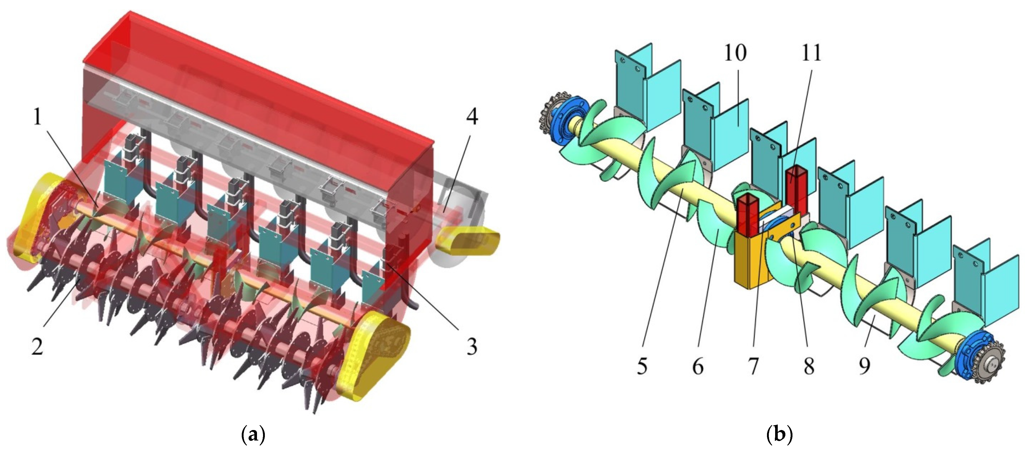
2.1. Machine Structure and Working Principle of the SSRSD

2.1.1. Structure of the SSRSD

The SSRSD was installed between the no-till anti-blocking knife group (2) and the furrowing opener group (3) of the wheat no-till planter, as shown in Figure 1a. The SSRSD designed in this paper was composed of six SSM (1), and its overall structure is shown in Figure 1b.
The SSRSD comprised RB (6), spiral shaft (5), straw hopper (9), straw baffle (10), rolling bearing (8), support-connecting frame (11), and spiral shaft positioning plate (7). The RB (6) was welded on the spiral shaft (5). The shaft heads of the two spiral shafts (5) passed through the center of the rolling bearing (8) and were installed in the spiral shaft positioning plate (7) on the support-connecting frame (11), which was welded on the frame (4). The straw hopper (9) was located just below the spiral shaft (5), and the top of the straw hopper (9) was connected to the bottom of the straw baffle (10) by bolts. Moreover, bolts fixed the top of the straw baffle (10) on the frame (4).
The SSM (1) comprised RB (6), spiral shaft (5), straw hopper (9), and straw baffle (10). Each SSM (1) consisted of two symmetrical row-sorting blades (SRB) arranged centrally symmetrically in the radial direction. Two mirror-symmetry RBs constituted each set of the SRB. Each SSM (1) was composed of four RBs. The position of each SSM corresponded to a sowing belt and corresponded to the no-till anti-blocking knife (2), and the furrowing opener (3) in the advancing direction.

2.1.2. Working Principle

The power of the SSRSD was provided by the rear output shaft of the tractor. When it was working, the high-velocity rotating no-till anti-blocking knife achieved the power-driven anti-blocking effect by cutting and chopping the soil and straw, ensuring the passing capacity of the machine.
As shown in Figure 2, under the high-velocity rotation of the no-till anti-blocking knife, most of the straw was thrown directly into the rear straw hopper. Alternatively, part of this straw was thrown to the front of the straw baffle and then fell in the straw hopper after hitting the straw baffle. The straw baffle played the role of preventing straw from falling into the seed belt. The SSM discharged the straw that fell into the straw hopper to both sides of the seeding belt, and the straw would fall to the non-sowing area between the seed belts under gravity to achieve the effect of seed belt cleaning. In addition, a small part of the straw was directly thrown into the non-sowing area between the seed belts by the no-till anti-blocking knife to row-sort the straw.

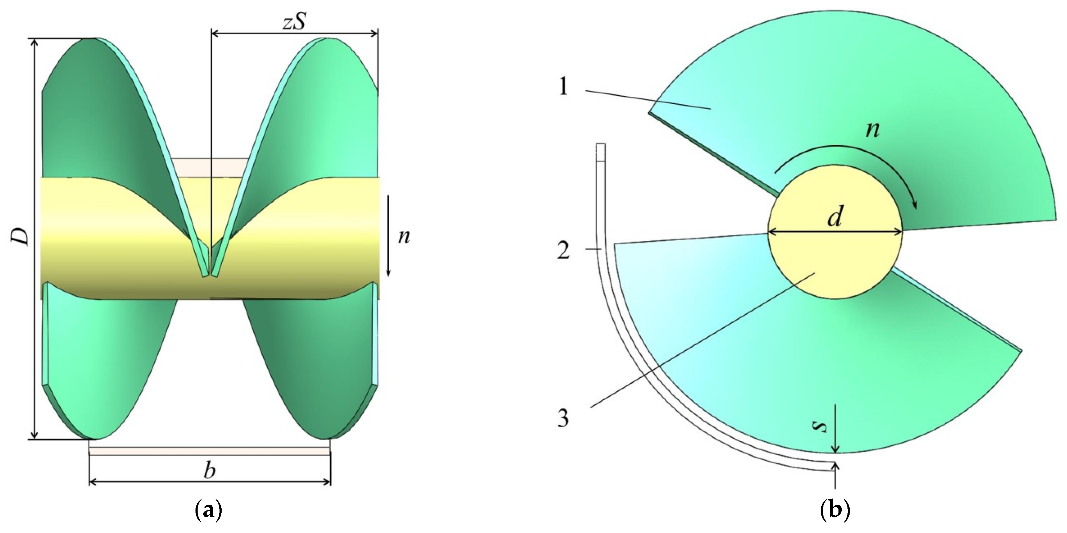
2.2. Determination of Critical Parameters of SSM

2.2.1. Calculation of Maximum Straw Feeding Amounts

The design basis of the critical parameters of the SSM should be focused on determining the relationship between its material bearing capacity limit and the straw feeding amounts (SFA) in the actual operation process. In the process of parameter design, the minimum material-bearing capacity of the SSM should be greater than the maximum SFA during the operation to ensure that the planter did was not blocked during the operation and the row-sorting of the straw effect was remarkable.
In order to determine the critical parameters of SSM, it was necessary to determine the maximum amounts of straw fed into the SSM at first. The maximum SFA could be obtained by transforming the SMQ of the actual operating environment. By referring to the literature [26], the conversion equation of SFA and the SMQ was shown in Equation (1):
Q = 1 60 C s v w b 2 λ
where Q is the SFA, kg/min; CS is the SMQ, kg/m2; v is the operating velocity of machines, km/h; w is the number of seeding belts corresponding to each SSM; b is the width of straw hopper, mm; λ is the SRR, %.
It could be seen from Equation (1) that the variables on the right side of the equation were all positively correlated with SFA Q, indicating that the larger the value of these variables, the greater SFA of the SSM. Therefore, the values of these variables should be relatively increased based on the actual operation situation to improve the operation stability of the machine.
The SMQ CS on the pre-operation field was randomly weighed by the five-point sampling method [27], ranging from 1.16 to 1.87 kg/m2. In order to improve the stability of straw conveying performance, the actual value of SMQ should be relatively increased, and it was taken as 2 kg/m2. The operating velocity v of machines was taken as the maximum velocity of 5 km/h. Each SSM corresponds to one sowing belt, and w was taken as 1. The width of the straw hopper and the sowing belt was equal, and their position was corresponding, b was 150 mm. The SRR λ was taken as the maximum value of 100%, and the maximum SFA Qmax of SSM was calculated by Equation (1) to be 12.5 kg/ min.

2.2.2. Determination of Critical Parameters

As shown in Figure 3, the critical parameters of the SSM were composed of several different parameters. It was essential to analyze which parameters had little influence on the conveying performance and could be obtained directly from the known conditions and which critical parameters needed to be designed. Because only a reasonable parameter ratio could maximize the conveying performance and row-sorting effect of the SSM on straw, identifying these critical parameters and determining their rational and reasonable values was the focus of the following research.
By referring to the corresponding content of the screw conveyor module in the “Agricultural Machinery Design Manual” [28], it could be known that the equation of the relationship between the material bearing capacity limit Qs of the SSM and the critical parameters of it was as follows:
Q s = π 4 [ ( D 2 s ) 2 d 2 ] ψ S n ρ C × 10 9
where Qs is the material-bearing capacity limit of the SSM, kg/min; D is the ODRB, mm; s is the gap between the RB and the straw hopper, mm; d is the DSS, mm; S is the pitch of the RB, mm; n is the RVSS, rpm; ψ is the filling factor when conveying the material, which is taken as 0.3; ρ is the density of the material, kg/m3; C is the inclined conveying coefficient of the straw hopper, which is taken as 1.
As shown in Figure 3, s was the gap between the RB and the straw hopper, and the value of s was designed as half of the average straw diameter in the working area. By measuring the diameter data of 20 groups of straws on the pre-operated field, the average diameter of straws was 4.32 mm, and s was taken as 2 mm. The straw density ρ was taken as 240 kg/m3. By referring to the literature [29,30], taking S = D, so the pitch S of the RB was determined by ODRB D. Therefore, the critical parameters that needed to be determined by the variable analysis were only the ODRB D, the RVSS n and the DSS d.

2.3. Kinematic Analysis Method to Determine the Rational and Reasonable Value of Critical Parameters

The kinematic analysis refers to the qualitative or quantitative analysis of the position change of the mechanism without considering the effect of force. The kinematic analysis method was often used to study the influence of different parameter ratios of the mechanism on the change of its motion trajectory [31,32]. Based on this, the following content would use the curve drawing software CAXA to establish the motion trajectory model of the SSM. In addition, the motion curve under different parameter ratios was optimized and simulated. Through the mechanism analysis, the influence law of each factor on the motion trajectory of the SSM was studied to determine the rational and reasonable structure size and operating parameters.

2.3.1. Kinematic Analysis Methods

The motion trajectory of any point on the ODRB of the SSM was synthetic. Precisely, the SSM moved in the forward direction of the no-till planter with the tractor’s traction and rotated at a fixed rotary velocity under the drive of the spiral shaft (the rotation direction was consistent with the no-till anti-blocking knife). The straw was discharged to the non-sowing area on both sides of the SSM. The absolute motion of the RB at any point on its outer diameter is composed of the machine’s forward motion and the rotational motion of the spiral shaft. Furthermore, its motion trajectory was in the form of a cycloid, and the corresponding equation was:
{ x = v t + R cos θ = v t + D 2 cos ( 2 π n t ) y = R sin θ = D 2 sin ( 2 π n t )
R = D 2 , θ = ω t = 2 π n t
where x is the displacement in the x-axis direction, m; y is the displacement in the y-axis direction, m; v is the operating velocity of machines, m/s; t is the time, s; R is the radius of gyration of the RB, m; θ is the rotation angle of the RB, rad; D is the ODRB, m; n is the RVSS, r/s; ω is the angular velocity of the RB, rad/s.
It could be seen from Equation (3) that the ODRB D and the RVSS n were directly related to its motion trajectory equation. For the DSS d, the motion trajectory equation of the RB could also be transformed into the motion trajectory equation of a point on the diameter of the spiral shaft by replacing D in Equation (3) with d. Therefore, the following would analyze the mechanism of the motion trajectory of the ODRB D, the RVSS n, and the DSS d to further improve the operating performance and operation effect of the SSRSD in theory analysis.

2.3.2. Determination of Rational and Reasonable Parameters Value Range

In order to obtain the rational and reasonable values of the ODRB D, the RVSS n, and the DSS d, according to Equation (2) for calculating the material bearing capacity of the SSM, the value range of the critical parameters was expanded. According to the existing theoretical basis, it was concluded that the value range of critical parameters was as follows:
{ D [ 150 , 250 ] n [ 100 , 120 ] d [ 60 , 80 ]
Considering that the values of the ODRB D and the RVSS n were positively correlated with the material-bearing capacity of the SSM, the value of the DSS d was negatively correlated with it. Therefore, by substituting the minimum value of D, the minimum value of n, and the maximum value of d in Equation (4) into Equation (2), it could be calculated that:
Q s = π 4 [ ( D 2 s ) 2 d 2 ] ψ S n ρ C × 10 9 = 12.65   kg / min > Q max = 12.5   kg / min
After theoretical analysis and verification, the minimum material-bearing capacity limit of the SSM was greater than the maximum SFA during the operation. Therefore, when the value range of the ODRB was 150~250 mm, the RVSS was 100~120 rpm, and the DSS was 60~80 mm. The material bearing capacity limit Qs of the SSM was greater than the maximum SFA Qmax in the working environment. The design of the parameter value range was reasonable and adequate.
Based on guaranteeing that the minimum material-bearing capacity limit of the SSM was greater than the maximum SFA during the operation, ensuring the machine could operate stably, it was still necessary to conduct a single-factor analysis of the specific values of critical parameters. Specifically, if the value of the ODRB D was too small, the row-sorting of the straw would be inefficient, limiting the operation stability and reliability of the machine to some degree. If the value of the RVSS n was small, the RB would throw the straw in the reverse direction so that more straw stayed on the sowing belt. If the value of the DSS d was too large, the effective operation rate of the RB would be reduced. All of the above situations would indirectly negatively impact the SRR and the passing capacity of the machine. Therefore, to further optimize the above critical parameters, the value range was divided into five equal parts, and the factors and levels were determined, as shown in Table 1. In the following content, the single factor analysis will be carried out on the influence of the above-mentioned critical parameters on the working effect under different values to determine the rational and reasonable structure and working parameters.

2.4. Field Test Method to Verify the Operating Performance of the SSRSD

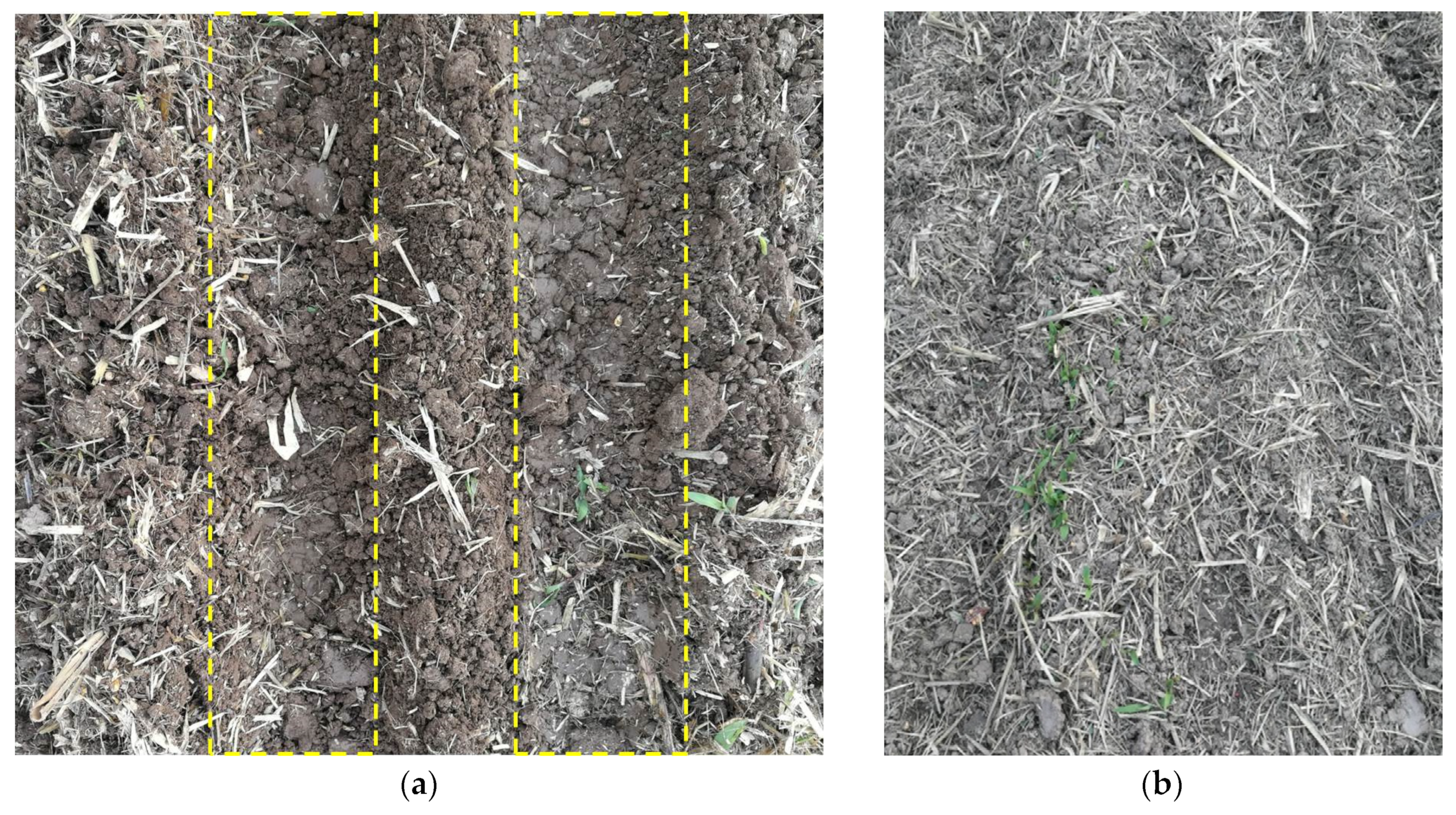
2.4.1. Field Test Conditions

In order to verify the actual operation effect of the SSRSD, a field verification test was carried out on 25 October 2021 in the test field of Luoyang Xinle mechanical equipment Co., Ltd., Luoyang, China (112°35′26″ E longitude, 34°43′21″ N latitude, 144 m above sea level, air pressure 1006.1 hPa). The previous crop in the test field was autumn maize planted in June of the same year, and the maize stalks had been chopped and returned to the field. The soil property of the test site was brown clay, the temperature on the test day was 18 °C (the average daily temperature was 11~20 °C), and there was no precipitation. The field conditions before the operation are shown in Figure 4. Due to the continuous rainfall, the soil and straw moisture content in the field was relatively high. The test conditions are shown in Table 2.

2.4.2. Index and Test Method

The Machine’s Passing Capacity

The machine’s passing capacity referred to the ability of a no-till planter to remove maize straw and weeds during operation to avoid machine blockage. The field trafficability test, respectively, verified the no-till planter’s passing capacity with the SSRSD and without it. According to the related content in the Agricultural Industry Standard of the People’s Republic of China NY/T 1768-2009 “Technical Specifications for Quality Evaluation of No-till Planters”, the machine should travel a round trip in the test area with a length of 60 m according to the ordinary operation velocity of wheat no-tillage sowing. No blocking or only once slight blocking was considered acceptable for each test.

The SRR of the Sowing Belt

At present, the straw cleaning effect of the seed belt cleaning device in China was mainly achieved by measuring the SRR of the sowing belt. The calculation method of the SRR in the sowing belt could be realized by weighing the changes in straw quality before and after the machine operation. The specific calculation equation was as follow:
λ = m 1 m 2 m 1 × 100 %
where λ is the SRR, %; m1 is the straw quality before the operation, kg; m2 is the straw quality after the operation, kg.

3. Results and Discussion

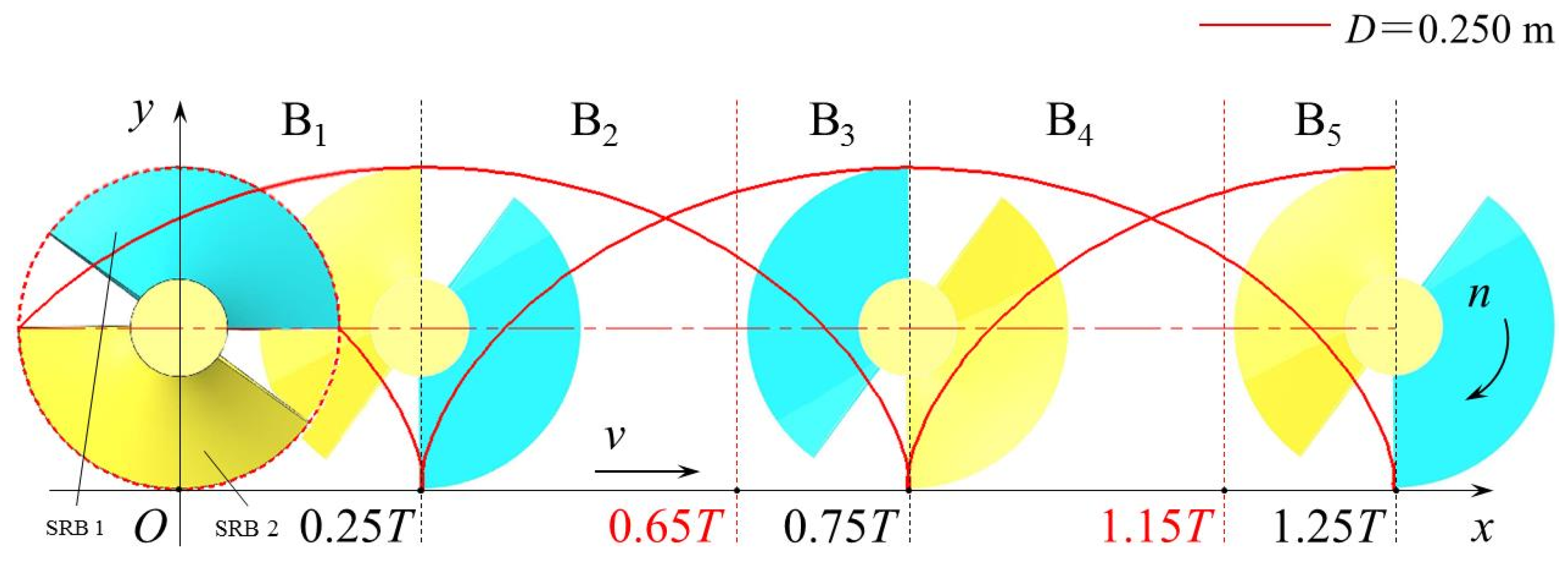
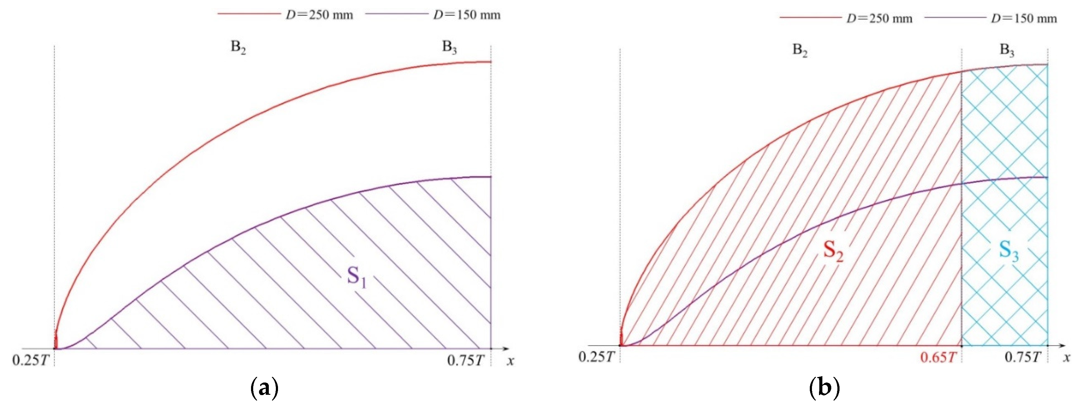
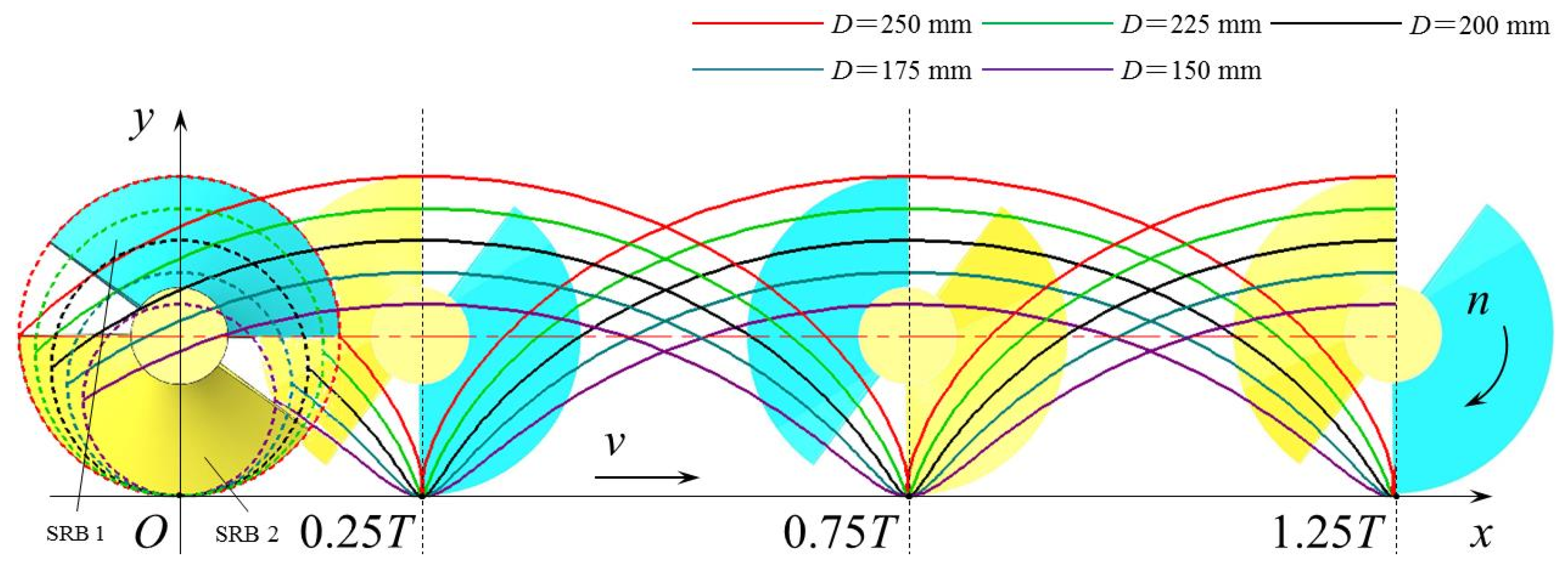
3.1. Determination of the ODRB D

As shown in Figure 5, the cycloids of different colors can indicate the motion trajectory of the tip of the SRB of the SSM when the ODRB D takes different values. It can be seen from Figure 5 that with the increase in the ODRB D, except for the increase in the cycloid amplitude, the motion law of the SRB has no significant changes. Therefore, in order to determine the rational and reasonable value of the ODRB D that could improve the reliability and stability of the SSM, the following content only analyzed the kinematic mechanism of the moving process of the variable’s interval endpoints (that was, when D = 150 mm and D = 250 mm).

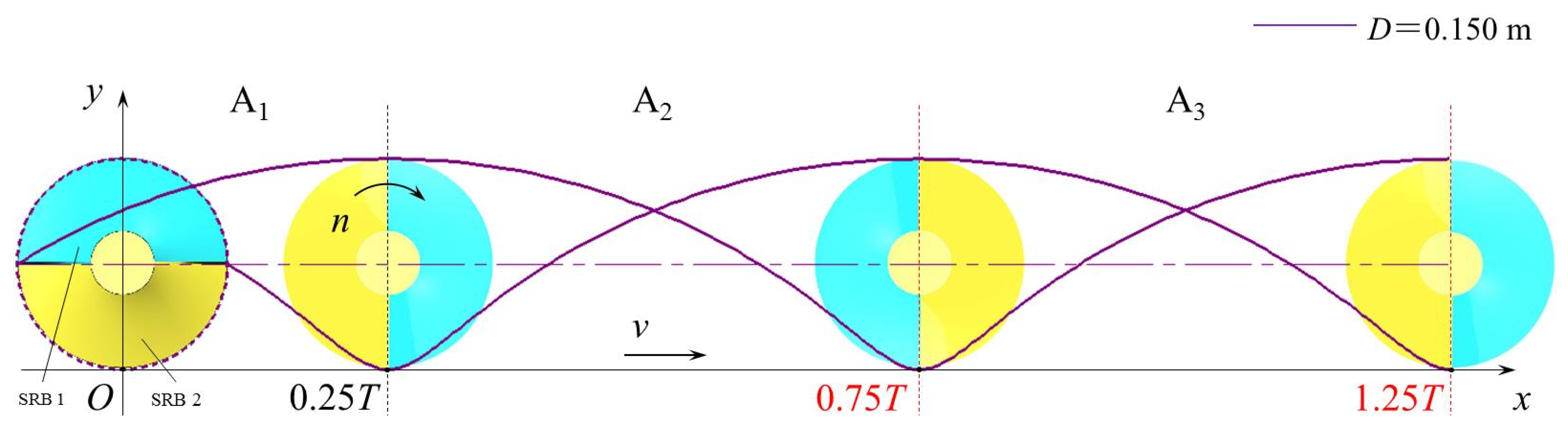
3.1.1. Analysis When the ODRB D = 150 mm

Firstly, some necessary basic parameters needed to be determined. When the ODRB D was taken as 150 mm, it could be determined from Equation (2) that S = D = 150 mm, then k = b/2S = 0.3. Considering that the number z of turns of the RBs was zk = 0.5, and when the number of groups of SRB was 2, there was z ≤ 0.5 (each group was assigned at most 180°), so the number of turns of the RBs was z = 0.5.
Secondly, determine the kinematic equation of the SSM. The operating velocity v of machines took the maximum operating velocity, that was, v = 5 km/h = 1.3889 m/s. The ODRB was D = 150 mm = 0.15 m. The RVSS n was fixed at 110 rpm (the law analysis and parameter determination of the RVSS were given in the following content), that was, n = 110 rpm = 1.8333 m/s. Then, substituting the above parameters into Equation (3), it could be determined that when the ODRB D = 150 mm, the kinematic equations of the tips of the SRB 1 and the SRB 2 were as follows:
SRB   1 s   equation   of   motion : { x = 1.3889 t + 0.075 cos ( 2 π 1.8333 t ) y = 0.075 sin ( 2 π 1.8333 t ) ,   when   D = 150   mm SRB   2 s   equation   of   motion : { x = 1.3889 t + 0.075 cos ( 2 π 1.8333 t π ) y = 0.075 sin ( 2 π 1.8333 t π ) ,   when   D = 150   mm
Finally, the motion trajectory of the SSM was analyzed. When SSM is in the position shown in Figure 6, this position is recorded as the initial position of the movement, that is, the moment of t = 0. The top blade is recorded as SRB 1, the bottom blade is SRB 2, and the motion trajectories at the tips of the two groups of SRB are analyzed, respectively.
For the SRB 1 (blue), when it revolves from the initial position to t = 0.25T (A1 area), the SRB 1 is not in contact with the straw and is idling. When t = 0.25T, the tip of the SRB 1 starts to contact the straw hopper, and the SRB 1 is ready to start discharging the straw on the hopper. When t is between 0.25T and 0.75T (A2 area), the SRB 1 starts to oblique thrust the straw and continuously discharges the straw on the hopper to the non-sowing areas on both sides of the sowing belt to realize the row-sorting of the straw effect. At the moment of t = 0.75T, the SRB 1 finishes the oblique thrusting operation, ultimately leaving the working position, and the SRB 2 starts to contact the straw hopper. In 0.25T~0.75T, the SRB 1 completes one process of row-sorting the straw. When the SRB 1 revolves to t = 1.25T, the SRB 1 will continue to repeat the above row-sorting of the straw process, and the cycle of each operation is 1T.
For the SRB 2 (yellow), when t is between 0 and 0.25T (A1 area), the SRB 2 is in the second half of the whole process of oblique thrusting the straw. In 0.25T~0.75T (A2 area), the SRB 2 does not oblique thrust the straw and is idling. In the following 0.75T~1.25T process (A3 area), the working principle of the SRB 2 is the same as that of the SRB 1 when it is in the A2 area and continuously discharges the straw flying into the hopper. At the moment of t = 1.25T, the SRB 1 replaces the SRB 2 and plays the role of oblique thrusting and row-sorting the straw.

3.1.2. Analysis When the ODRB D = 250 mm

When the ODRB D was 250 mm, it was calculated by Equation (2) that S = 250 mm, k = 0.3. The number of groups of SRB was still taken as 2, and there was 0.3 ≤ z ≤ 0.5, taking the median value as 0.4. Substituted the operating velocity of machines v = 5 km/h, the ODRB D = 250 mm, the RVSS n = 110 rpm into Equation (3), and the kinematic equations of the tips of the SRB 1 and the SRB 2 could be determined as follows:
SRB   1 s   equation   of   motion : { x = 1.3889 t + 0.125 cos ( 2 π 1.8333 t ) y = 0.125 sin ( 2 π 1.8333 t ) ,   when   D = 250   mm SRB   2 s   equation   of   motion : { x = 1.3889 t + 0.125 cos ( 2 π 1.8333 t π ) y = 0.125 sin ( 2 π 1.8333 t π ) ,   when   D = 250   mm
When taking ODRB D as 250 mm, the motion trajectory of the tip of the SRB of the SSM is shown in Figure 7. Under the condition that the operating velocity v of machines and the RVSS n remain unchanged, the prevailing law of its motion is basically unchanged compared with the case when D = 150 mm. However, due to the increase in ODRB, the magnitude of cycloid amplitude and the value range of the number z of turns gradually increase. Moreover, this changes the overall time of the working. The operation time of row-sorting straw to the non-sowing area on both sides of the seed belt by SRB 1 changes from 0.25T~0.75T to 0.25T~0.65T (A2B2), and the operation time of SRB 2 to do this changes from 0.75T~1.25T to 0.75T~1.15T (A3B4). Specifically, the operation time is shortened by 0.1T. In addition, the shortened part of the time is supplied for the buffer/idle area (B3, B4) during the operation of the two groups of SRB.

3.1.3. Mechanism Analysis of Motion Trajectory and Determination of ODRB D

Based on the above analysis and combined with Figure 6 and Figure 7, it can be found that the RVSS n, the DSS d, and the operating velocity v of machines are fixed. When the value of the ODRD D changes, the main changes are the value range of the two factors, the cycloid amplitude and the number z of turns of the RB. Therefore, the following will analyze the influence of the changes of the above two factors on the working effect of the SSM to determine the rational and reasonable value of the ODRB D.
The effect of the change of the ODRB on the cycloid amplitude was that essentially when the ODRB D was different, the amount of straw that the RB could discharge was different. It can be seen from Equation (2) that the ODRB D and the material-bearing capacity limit Qs of the SSM were positively correlated. When the ODRB D increased, the material bearing capacity limit Qs of the SSM increased in a power function. Combined with Figure 8, the area of area-S1 is enclosed by the motion trajectory of tips of SRB (purple line), the x-axis, and the line of x = 0.75T when D = 150 mm. Area-S1 can express the total amount of straw that can be discharged by a set of SRBs when ODRB D is 150 mm in a complete operation cycle T. Similarly, the area of area-S2 is enclosed by the motion trajectory of the tips of SRB (red line), the x-axis, and the line of x = 0.65T when D = 250 mm. Area-S2 can express the total amount of straw discharged by a set of SRBs when ODRB D is 250 mm in a complete operation cycle T. Substituted Equations (7) and (8) into MatLab software to calculate the area of S1 and S2 in Figure 8. The calculation result was S1 = 134,100 mm2, S2 = 196,800 mm2, S2 > S1. It could be shown that when ODRB D is 250 mm, the material-bearing capacity limit Qs of the SSM is significantly improved compared with D being 150 mm.
Regarding the number z of turns of the SRB, it could be known from the above analysis that when the ODRB D was 150 mm, the total width of the straw hopper was fixed at 150 mm, the number z of turns could only be equal to 0.5. However, when the ODRB D was 250 mm, the value range of the number z of turns of the SRB was more flexible, which was expanded to z∈[0.3, 0.5]. If D = 150 mm, the number z of turns of the SRB was equal to 0.5, there was no gap in the axial direction of the arrangement of the two groups of SRB, and the process of straw discharging was always continuous. However, when the value of the number z of turns of the SRB was reduced, the gap between the two sets of SRB was relatively enlarged. During the process of straw discharging, there is a buffer/idling area at the gap (S3 area in Figure 8), the operating strength of the SSM and the possibility of blocking were reduced, and the reliability and stability of the machine’s operation process were improved.
In designing the critical parameters of the SSM, based on increasing the ODRD D to improve the material-bearing capacity limit Qs of the SSM, the value of the number z of turns of the SRB could be relatively reduced. On the premise of ensuring the material-bearing capacity, it could improve the operating reliability and operation stability of the SSM and reduce the possibility of machine blockage. In summary, the ODRB D was selected as 250 mm.

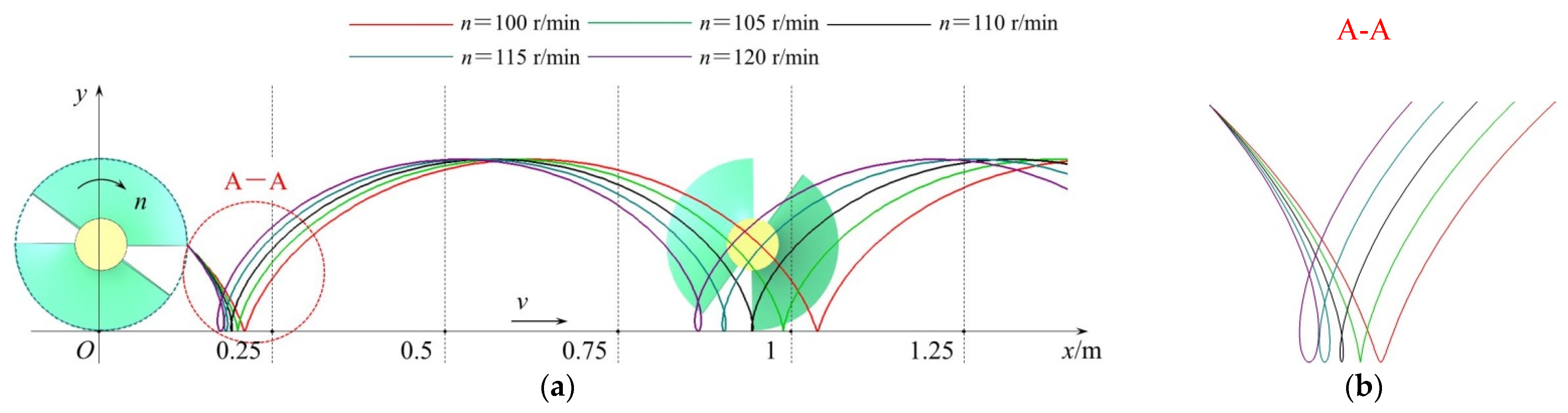
3.2. Determination of the RVSS n

The RVSS was an essential working parameter of the SSM, which was directly related to the mechanism’s straw discharging capacity and work efficiency. If the designed rotary velocity were low, the working efficiency of the RB to thrust the straw would be reduced, and the possibility of blockage of the SSM would be increased. Suppose the RVSS gradually increased under the premise that the operating velocity of machines was fixed. The trajectory of the tip of the RB would gradually change to a trochoidal form [33]. In this case, the RBs could throw soil and straw backward, and the SRR was significantly improved under the increased row-sorting repetition rate. However, the tangential component of the normal thrust of RB and the frictional force of the blade on the straw would rotate the straw around the spiral shaft. Suppose the design rotary velocity was too high. The centrifugal force would gradually replace the blade’s thrust to play the leading role. The straw would be thrown outward due to the excessive centrifugal force, which would seriously affect the row-sorting effect of the RB on the straw. Therefore, a rational and reasonable design of the RVSS was necessary to improve the working effect and efficiency of the SSM. The RVSS should be decreased as much as possible based on preventing the blockage of SSM and ensuring the blade’s effectiveness in row-sorting the straw.
It could be seen from Equations (2), (4) and (5) that when the RVSS n > 100 rpm, the minimum material-bearing capacity of the SSM was greater than the maximum SFA during the operation, and the SSM would not incur blockage. Substituting the operating velocity of machines v = 5 km/h, the ODRB D = 250 mm, and the optimal parameter range n∈[100, 120] of the RVSS into Equation (3), obtained the motion trajectory equation of the tip of the RB when the value of n was different. Using the equation curve module in the 2D drawing software CAXA, the motion trajectory curve of the tip with different n values is drawn, as shown in Figure 9.
It can be seen from Figure 9 that when the RVSS n < 110 rpm, the motion trajectory of the tip of the RB is a curtate cycloid. At this time, the RB of the SSM cannot throw soil and straw to the oblique rear, and the effect and performance of row-sorting the straw decrease significantly so that the SSM cannot operate normally. When the RVSS n ≥ 110 rpm, its motion trajectory is a trochoid, and the RB can throw soil and straw to the oblique rear. The motion trajectory of each point is a trochoid, which can achieve the ideal straw row-sorting effect. To sum up, select the minimum rotary velocity required by the spiral shaft as the operating rotary velocity of the machine in the case that the curve of the motion trajectory is a trochoid, that is, n = 110 rpm. Its kinematic equation is as follows:
{ x = 1.3889 t + 0.125 cos ( 2 π 1.8333 t ) y = 0.125 sin ( 2 π 1.8333 t ) ,   when   n = 110   r / min

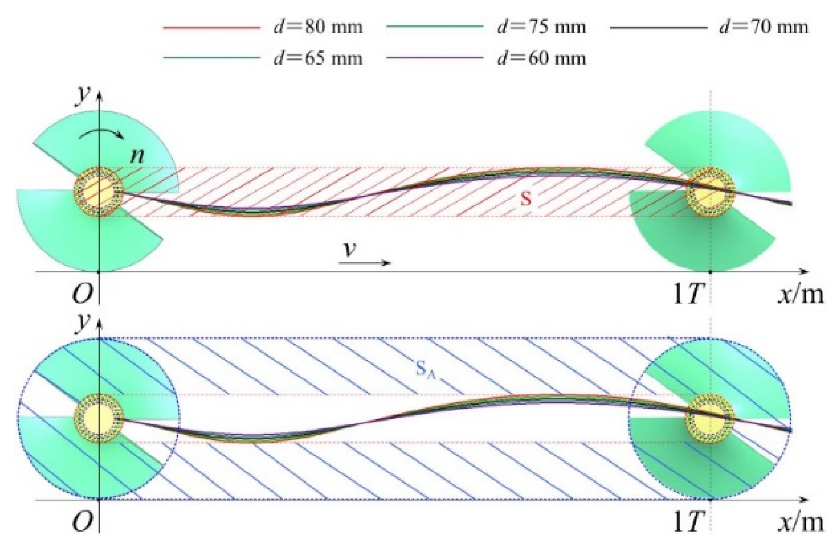
3.3. Determination of the DSS d

It could be seen from Equation (2) that the value of the DSS d would also affect the material-bearing capacity of the SSM. When the value of the DSS d was too small, the mechanical properties of the spiral shaft were poor, and the strength and stiffness were weak. With the SSM row-sorting the straw through the rotary of the spiral shaft, the spiral shaft was prone to failure modes such as plastic deformation and fatigue fracture, which seriously affected the operation stability of the SSM. However, if the value of the DSS d were too large, it would make the SSM bulkier and increase unnecessary costs and energy consumption. In addition, the effective operating area of the RB would be excessively reduced, which would restrict the working effect of the SSM. Therefore, it was necessary to design rational and reasonable parameters for the DSS d, which would improve the mechanical performance of the spiral shaft and, at the same time, achieve the purpose of guaranteeing the operating performance of the SSM.

3.3.1. Calculation of the Minimum Value of the DSS d

First, calculate the minimum value of the DSS. By referring to the “Mechanical Design” [34], the calculation equation of the DSS was as follows:
d A 0 ( P n ( 1 β 4 ) ) 1 3
where d is the DSS, mm; A0 is the shaft diameter coefficient; P is the power transmitted by the spiral shaft, kW; n is the RVSS, rpm; β is the hollow shaft coefficient, which is taken as 0.6.
The material of the spiral shaft was 45 steel. In the process of straw row-sorting, the spiral shaft was mainly affected by torque, and the load was relatively stable. By referring to the literature [34], the shaft diameter coefficient A0 was taken as 103. Considering that the SSRSD was installed on a 2BMQF-6/12A no-tillage fertilizer planter, by referring to the data [35], the calculated power of the rear output shaft of the tractor was 58.8~66.2 kW. Because these energies were provided to the no-till anti-blocking knife group and SSM simultaneously, the no-till anti-blocking knife group was a soil-contacting component and consumed a large amount of power. Moreover, the power consumed by the two spiral shafts was theoretically less than half of the total power (two sets of SSM equipped with two shafts and two sets of no-till anti-blocking knife groups were also equipped with two shafts, with a total of four shafts). The maximum power P transmitted by a single spiral shaft took 15 kW. The RVSS n was taken as 110 rpm. The minimum value of the DSS d was calculated by Equation (10) as 55.5 mm, and dmin was taken as 60 mm.

3.3.2. Influence of DSS d change on Ineffective Operation Rate η

Because the spiral shaft could not discharge the straw, the area covered by the spiral shaft with the advancing process of the machine could be expressed as the ineffective operation area of the SSM. In addition, the ineffective operation area of the SSM could be represented by the size of the lateral area of the area where the spiral shaft could not discharge the straw. It can be seen from Figure 10 that the red shaded area S in this figure can represent the lateral area of the area where the spiral shaft could not discharge the straw in a period T, that is, the ineffective operation area of SSM. The calculation equation of S was as follows:
{ S = π ( d 2 ) 2 + 1000 v T d 2 S A = π ( D 2 ) 2 + 1000 v T D 2 S η = S S A × 100 %
where S is the ineffective operation area of the SSM, mm2; d is the DSS, mm; v is the operating velocity of machines, m/s; T is the cycle of the spiral shaft rotates one turn, s; SA is the effective operation area of the SSM, mm2; η is the ineffective operation rate of the SSM, %.
However, in the actual operation process, the oblique area S (red shaded area) of the ineffective operation area of the SSM is much smaller than the oblique area SA (blue shaded area) of its effective operation area. It is not scientific and accurate to only use the numerical value of S to express the influence of the DSS of different sizes on the operation effect. It should be expressed by the ratio of the area of the ineffective operation area S to effective operation area SA, that is, the ineffective operation rate η of the SSM.
The calculation method of η was shown in Equation (11). It could be seen from the above analysis that the operating velocity of machine v = 1.3889 m/s, and when the RVSS n = 110 rpm, the cycle T = 1/n = 0.5455 s. Substitute the DSS d∈[60, 80] into Equation (11). The calculation results of the ineffective operation area S, the effective operation area SA and the ineffective operation rate η of the SSM with different values of the DSS d are shown in Table 3. As the DSS d increases from 60 mm to 80 mm, the ineffective operation rate η increases by 33.59% within one cycle T.

3.3.3. The influence of DSS d change on the structural strength τT

In terms of the strength calculation of the spiral shaft, during the operation of the machine, there was no additional bending moment during the rotary of the spiral shaft, and the load was relatively stable. By referring to the literature [34], the calculation equation of the torsional strength of the spiral shaft was as follows:
τ T = T T W T 9   550   000 0.2 d 3 P n [ τ T ] = 45   MPa
where τT is the torsional shear stress on the spiral shaft, MPa; TT is the torque on the spiral shaft, N mm; WT is the torsional section coefficient of the spiral shaft, mm; n is the RVSS, rpm; P is the power transmitted by the spiral shaft, kW; d is the DSS, mm; [τT] is the allowable torsional shear stress of the spiral shaft, MPa.
It was verified that the torsional shear stress on the spiral shaft was less than its allowable torsional shear stress. The calculation results of torsional shear stress for different sizes of the spiral shaft are shown in Table 4 when substituting the above parameters into Equation (12). When the DSS was d∈[60, 80], the torsional shear stress on the spiral shaft was less than the allowable torsional shear stress of 45 MPa, and the design of the structure size was reasonable. As the DSS increased from 60 mm to 80 mm, its structural strength increased by 57.81%.

3.3.4. Determination of the Value of the DSS d

As the DSS d increased from 60 mm to 80 mm, the ineffective operation rate η was increased by 33.59% in the same cycle. The structural strength of the spiral shaft was increased by 57.81%. As the DSS increased, the structural strength was higher than the ineffective operation rate. With careful consideration, the DSS should appropriately increase. The vast improvement of the operation reliability and stability of the SSM could be achieved by improving the structural strength of the spiral shaft. Combined with the national standard of shaft parts and the actual size of the existing blanks, the DSS d was selected as 76 mm.

3.4. Design Results of Main Structural Parameters

Combined with the agronomic requirements of winter wheat no-tillage sowing in Huang-Huai-Hai annual double cropping areas in China, for example, the width of the sowing belt was 150 mm. The main technical parameters of the SSRSD were determined to realize the straw row-sorting and seed belt cleaning of the no-tillage planter, as shown in Table 5.

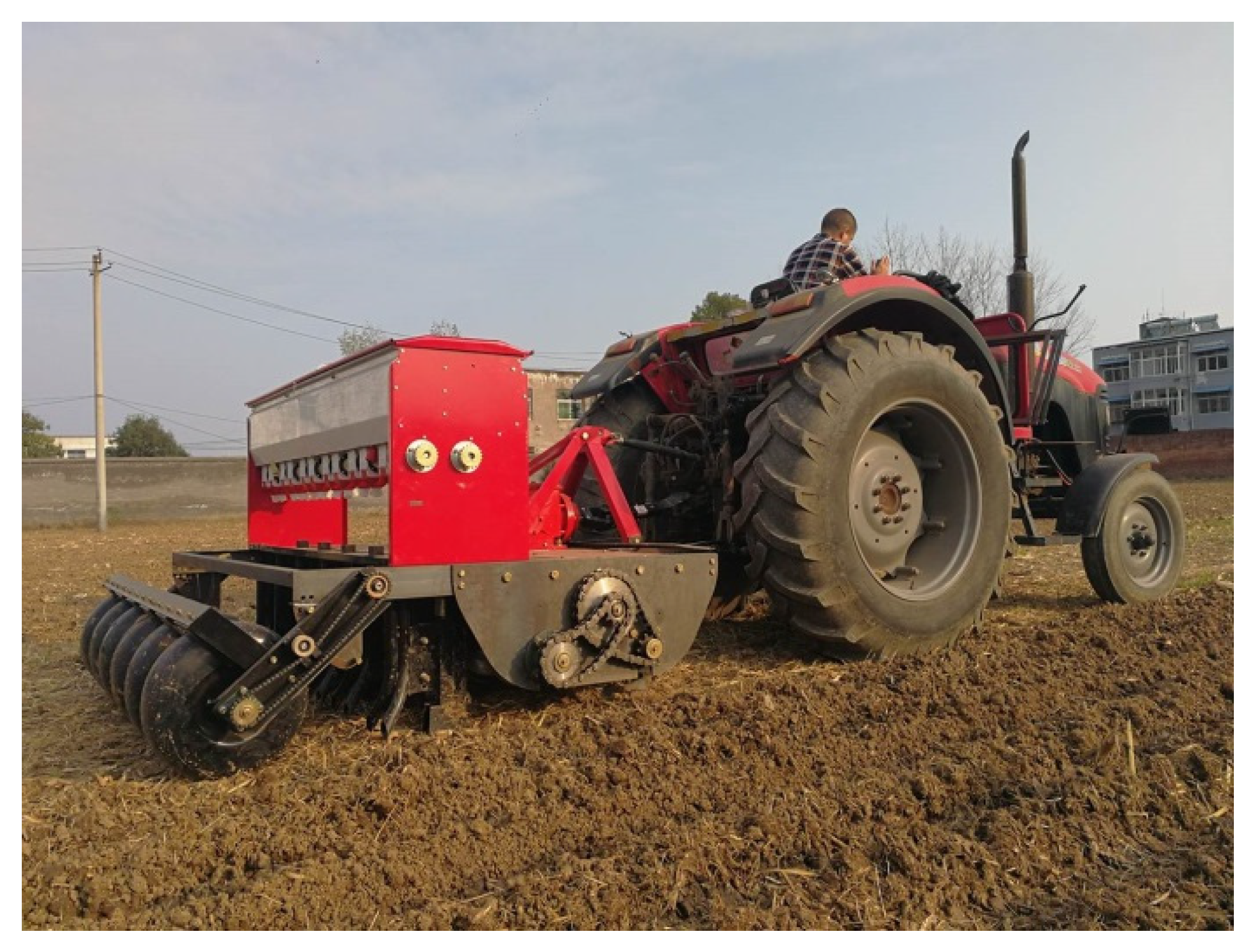
3.5. Field Test Verification

3.5.1. The Machine’s Passing Capacity

According to the critical parameters determined above, processing and manufacturing of the SSRSD with ODRB, d = 250 mm, RVSS n = 110 rpm, and DSS d = 76 mm. It was installed on the 2BMQF-6/12A no-tillage fertilization planter to carry out the passing capacity test of the machine. The field test site is shown in Figure 11.
The test results show that the wheat no-till planter equipped with the SSRSD had a fluent operation process, and there was still no blockage under the condition of high damp of soil and straw. Through actual observation, the no-till planter installed with the SSRSD had alleviated the phenomenon of clay sticking and grass. The passing capacity and operation stability of the machine improved.

3.5.2. The SRR of the Sowing Belt

Before the field test, the five-point sampling method [27] was firstly used on the field surface of the 20 m part of the middle of the 60 m pre-work test area and weighed the average SMQ using a square metal frame of 0.25 m2 and an electronic balance. It was taken as the mass of straw on the sowing belt before an operation. After weighing, the formal test was carried out, and the planter examined the straw-cleaning effect on the sowing belt at an average velocity of 5 km/h in a test area of 60 m length. Considering that the variable operation velocity at the planter’s start-point and end-point might affect the measurement results, the site with a relatively uniform operation in the middle was selected to measure the SRR. Finally, taking 10 consecutive weighing positions at an interval of 1 m, in the stable operation area as the measurement points, the weight of the residual mass of straw on the sowing belt after an operation was weighed by the electronic balance, and the average value was taken as the final data. The final SRR in the sowing belt after the operation was calculated according to Equation (6).
The actual effect of cleaning the sowing belt after the operation is shown in Figure 12, and the test results of the SRR of the sowing belt are shown in Table 6.
Combined with Figure 12 and Table 6, the average SRR of the no-till planter installed with the SSRSD is 87.98%, and the average SRR of the no-till planter installed without the SSRSD is 72.91%. The SRR was increased by 20.7%, and the cleaning effect of the sowing belt was significantly improved, which could effectively improve the quality of wheat no-till sowing while ensuring the passing capacity of machines.

3.6. Discussion

Combined with the actual value of the SMQ on the test field, the minimum value calculated according to the theoretical analysis is 150 mm. Furthermore, according to Equation (2), the rational and reasonable value range of ODRB D is 150~250 mm. The relationship between different values of ODRB D and the material bearing capacity limit is analyzed above, which is the same as Chen’s [31] design concept of the stalk collecting spiral device in the critical component design.
Li [26] analyzed the relationship between RVSS n and SRR by discrete element simulation method and found there were negatively correlated. As the RVSS decreases, the SRR tends to increase gradually. Therefore, the RVSS n should be designed as a relatively small value, and in the case of agricultural mechanics [33], when the operating velocity of machines v and ODRB D is fixed, the larger the RVSS n, the more significant the trochoidal form of the trajectory of the tip of the RB. It will have a positive correlation with the operation effect of SSM. Therefore, the value of RVSS n is the lowest rotary velocity value at which the trajectory of the tip of the RB takes the trochoidal form.
The parameter design of DSS d combines relevant theories in mechanical design [34]. On the premise of ensuring sufficient structural strength of DSS, the value of DSS d should be set as a correspondingly small value, which can improve the operation effect of SSM.

4. Conclusions

(1)
In this paper, an SSRSD was designed. The high-velocity rotating no-till anti-blocking knife cut and chopped the straw and threw it to the rear SSM during the operation. Based on the spiral shaft rotary, the RB of the SSM pushed the straw that fell into the straw hopper to the non-sowing area on both sides of the sowing belt and played the role of row-sorting the straw. It realizes the cleaning of the seed belt while alleviating the blockage of the machines.
(2)
The relationship between the material-bearing capacity limit of the SSM and the SFA (that was, the SMQ) in the actual operation process was theoretically analyzed. The critical parameters of the SSM were determined as the ODRB D, the RVSS n, and the DSS d. The rational and reasonable value range was D∈[150, 250], n∈[100, 120], d∈[60, 80].
(3)
Based on the kinematics analysis method, the motion trajectory mechanism of the RB of the SSM was analyzed, and the rational and reasonable values of the critical parameters were determined. Namely, the ODRB was 250 mm, the RVSS was 110 rpm, and the DSS was 76 mm. Based on the values of the above critical parameters, a field test was carried out after the prototype was manufactured. The results show that the no-till planter installed with the SSRSD was 87.98%, and the average SRR of the no-till planter installed without the SSRSD was 72.91%. The SRR was increased by 20.7%, and the cleaning effect of the seed belt was significantly improved, which could simultaneously improve the passing capacity of the machine and the quality of wheat no-till sowing.
The further research plan is to find an effective method to optimize the SSRSD operation index, determine the key factors and corresponding levels that have a significant impact on the machine’s passing capacity and the SRR of the sowing belt through the experimental design, and obtain a better structure and work parameter through computer simulation experiments. Moreover, it is also worth considering the reliability tests of machines; we will use some theoretical analysis or further exploration to quantify the durability, maintainability, and preservation ability of technical facilities [36].

5. Patents

Patents for the symmetrical spiral row-sorting of the straw device reported in this article have been applied for in China (Authorization announcement No.CN113748765B).

Author Contributions

Conceptualization, Y.L. and C.L.; methodology, Y.L., X.W. and D.H.; software, Y.L., Z.W. and Z.G.; writing—original draft preparation, Y.L. and C.L.; writing—review and editing, Y.L., C.L., H.L., Z.W., Z.G., X.W. and D.H.; funding acquisition, C.L. and H.L. All authors have read and agreed to the published version of the manuscript.

Funding

This research was funded by Study on wheat uniform-seeding mechanism for pneumatic pinhole tube seeding meter under wide-strip seedling zone system based on single-seed separating and stable feeding in low-position (Grant No.52175260), the China Agriculture Research System of MOF and MARA (Grant No.CARS-03), University Synergy Innovation Program of Anhui Province (Grant No.GXXT-2020-011), Innovative Research Team in University of China (Grant No.IRT13039), and the 2115 Talent Development Program of China Agricultural University and Chinese Universities Scientific Fund (Grant No.2021TC105).

Institutional Review Board Statement

Not applicable.

Informed Consent Statement

Not applicable.

Data Availability Statement

Not applicable.

Acknowledgments

The authors would like to thank the Conservation Tillage Research Center for its support.

Conflicts of Interest

The authors declare no conflict of interest.

References

  1. He, J.; Li, H.; Chen, H.; Lu, C.; Wang, Q. Research progress of conservation tillage technology and machine. Trans. Chin. Soc. Agric. Mach. 2018, 49, 1–19. [Google Scholar] [CrossRef]
  2. Wang, Q.; Cao, X.; Wang, C.; Li, H.; He, J.; Lu, C. Research progress of no/minimum tillage corn seeding technology and machine in northeast black soil regions of China. Trans. Chin. Soc. Agric. Mach. 2021, 52, 1–15. [Google Scholar]
  3. Liu, W.; Li, W.; Zheng, K.; Zhao, H. The current research status of conservation tillage technology. J. Agric. Mech. Res. 2017, 39, 7. [Google Scholar] [CrossRef]
  4. Department of Agricultural Mechanization Management. Ministry of Agriculture. Conservation Tillage in China; China Agricultural Press: Beijing, China, 2008.
  5. Liu, J.; Cui, Z.; Ma, J.; Wei, J. Problems and countermeasures of wheat corn rotation production mechanization for main crops in huanghuaihai region. J. Agric. Mech. Res. 2016, 38, 259–263. [Google Scholar] [CrossRef]
  6. Central People’s Net of the People’s Republic of China. Available online: http://www.gov.cn/xinwen/ (accessed on 8 October 2021).
  7. Li, H.; Liu, H.; Zhou, J.; Wei, G.; Shi, S.; Zhang, X.; Zhang, R.; Zhu, H.; He, T. Development and first results of a no-till pneumatic seeder for maize precise sowing in Huang-Huai-Hai plain of China. Agriculture 2021, 11, 1023. [Google Scholar] [CrossRef]
  8. Lu, C.; Li, H.; He, J.; Wang, Q.; Sarker, K.K.; Li, W.; Lu, Z.; Rasaily, R.G.; Li, H.; Chen, G. Effects of controlled traffic no-till system on soil chemical properties and crop yield in annual double-cropping area of the north china plain. Soil Res. 2016, 54, 760–766. [Google Scholar] [CrossRef]
  9. Lu, C.; Zhao, C.; Meng, Z.; Wang, X.; Wu, G.; Gao, N. Straw friction characteristic based on rotary cutting anti-blocking device with slide plate pressing straw. Trans. Chin. Soc. Agric. Eng. 2016, 32, 83–89. [Google Scholar] [CrossRef]
  10. Lu, C. Study on anti-blocking technology and device of rotary cutting with slide plate pressing straw for no-till planter. Ph.D. Thesis, China Agricultural University, Beijing, China, May 2014. [Google Scholar]
  11. Lu, C.; He, J.; Li, H.; Wang, Q.; Zhang, X.; Liu, J. Finite element analysis and experiment on anti-blocking device based on support cutting. Trans. Chin. Soc. Agric. Mach. 2013, 44 (Suppl. 1), 61–66. [Google Scholar] [CrossRef]
  12. Lu, C.; Li, H.; He, J.; Zhu, H.; Xu, D. Floated support anti-blocking device of wheat no-till seeder. Trans. Chin. Soc. Agric. Eng. 2013, 44, 52–55+153. [Google Scholar] [CrossRef]
  13. Yuan, P.; Li, H.; Jiang, G.; He, J.; Lu, C.; Huang, S. Design and experiment of straw cleaning device for wide narrow maize no-tillage sowing strip in drip irrigation area. Trans. Chin. Soc. Agric. Mach. 2021, 52, 43–52. [Google Scholar] [CrossRef]
  14. Yu, C.; Wang, Q.; Li, H.; He, J.; Lu, C. Design and experiment of spiral-split sowing strip cleaning device. Trans. Chin. Soc. Agric. Eng. 2020, 51 (Suppl. 2), 212–219. [Google Scholar]
  15. Liu, J.; Wang, H.; Wang, Q.; Li, S.; Li, H.; He, J. Design and experiment of strip cleaning device of no and minimum-tillage corn planter. Trans. Chin. Soc. Agric. Mach. 2018, 49 (Suppl. 1), 132–140. [Google Scholar] [CrossRef]
  16. Zhao, H. Study on Driven Seedbed-Cleaning and Anti-Blocking Device of Residue Inter-Row Side-Throwing for Minimum till Wheat Seeding; China Agricultural University: Beijing, China, 2019. [Google Scholar]
  17. Zheng, Z. Study on Corn Straw Pickup-Chopping and Ditch-Burying Returning Field Machine; China Agricultural University: Beijing, China, 2017. [Google Scholar]
  18. He, J.; Li, H.; Wang, Q.; Gao, H.; Li, W.; Zhang, X.; McGiffen, M. The adoption of conservation tillage in China. Ann. N. Y. Acad. Sci. 2010, 1195, E96–E106. [Google Scholar] [CrossRef]
  19. He, J.; Zhang, Z.; Li, H.; Wang, Q. Development of small/medium size no-till and minimum-till seeders in Asia: A review. Int. J. Agric. Biol. Eng. 2014, 7, 1–12. [Google Scholar] [CrossRef]
  20. Cao, X.; Wang, Q.; Li, H.; He, J.; Lu, C. Design and experiment of active rotating collective straw-cleaner. Trans. Chin. Soc. Agric. Eng. 2021, 37, 26–34. [Google Scholar] [CrossRef]
  21. Cao, X.; Wang, Q.; Li, H.; He, J.; Lu, C. Combined row cleaners research with side cutter and stubble clean disk of corn no-till seeder. Trans. Chin. Soc. Agric. Mach. 2021, 52, 9. [Google Scholar] [CrossRef]
  22. Wang, Q.; Jia, H.; Zhu, L.; Li, M.; Zhao, J. Design and experiment of star-toothed concave disk row cleaners for no-till planter. Trans. Chin. Soc. Agric. Mach. 2019, 50, 68–77. [Google Scholar]
  23. Wang, Q. Research on Key Technologies of Inter-Row Clean-Tillage and Its Strip-Till Machine; Jilin University: Changchun, China, 2019. [Google Scholar]
  24. Lin, J.; Li, B.; Li, H. Design and experiment of Archimedes spiral type stubble breaking ditching device and stubble breaking anti blocking device. Trans. Chin. Soc. Agric. Eng. 2015, 31, 10–19. [Google Scholar] [CrossRef]
  25. Lin, J.; Li, B.; Li, B.; Niu, J.; Qian, W. Parameter optimization and experiment on archimedes spiral type of gap cutting disc. Trans. Chin. Soc. Agric. Mach. 2014, 45, 118–124. [Google Scholar] [CrossRef]
  26. Li, Y.; Lu, C.; Li, H.; He, J.; Wang, Q.; Huang, S.; Gao, Z.; Yuan, P.; Wei, X.; Zhan, H. Design and Experiment of Spiral Discharge Anti-Blocking and Row-Sorting Device of Wheat No-Till Planter. Agriculture 2022, 12, 468. [Google Scholar] [CrossRef]
  27. Ni, H.; Lu, F.; Luo, X.; Tian, H.; Wang, J.; Guan, Y.; Chen, S.; Luo, X.; Zeng, E. Assessment of sampling designs to measure riverine fluxes from the pearl river delta, china to the south china sea. Environ. Monit. Assess. 2008, 143, 291–301. [Google Scholar] [CrossRef]
  28. China Academy of Agricultural Mechanization. Agricultural Machinery Design Manual; China Agricultural Science and Technology Press: Beijing, China, 2007; Volume 2. [Google Scholar]
  29. Yuan, Q.; Xu, L.; Niu, C.; Ma, S.; Yan, C.; Zhao, S.; Liu, F.; Wang, K. Development of soil-fertilizer mixing layered backfiller for organic fertilizer deep applicator in orchard. Trans. Chin. Soc. Agric. Eng. 2021, 37, 11–19. [Google Scholar] [CrossRef]
  30. Transportation Machinery Design and Selection Manual Committee. Transport Machinery Design and Selection Manual, the Next Volume; Chemical Industry Press: Shanghai, China, 1999. [Google Scholar]
  31. Chen, G.; Lu, C.; He, J.; Wang, C.; Wang, X.; Wang, Q. Design and experiment of straw pickup-crushed and deep buried device under strip-tillage. Trans. Chin. Soc. Agric. Mach. 2021, 52, 16–27. [Google Scholar]
  32. Li, T.; Huang, S.; Niu, Z.; Hou, J.; Wu, Y.; Li, Y. Optimization and experiment of planting perpendicularity of planetary wheel garlic planter. Trans. Chin. Soc. Agric. Eng. 2020, 36, 37–45. [Google Scholar]
  33. Li, B. Agricultural Mechanics; China Agricultural Press: Beijing, China, 2003. [Google Scholar]
  34. Pu, L.; Chen, G.; Wu, L. Mechanical Design, 9th ed.; Higher Education Press: Beijing, China, 2013. [Google Scholar]
  35. General Purpose Agricultural Machinery. Available online: https://www.nongjitong.com/product/33800.html (accessed on 1 January 2022).
  36. Durczak, K.; Selech, J.; Ekielski, A.; Żelaziński, T.; Waleński, M.; Witaszek, K. Using the Kaplan–Meier Estimator to Assess the Reliability of Agricultural Machinery. Agronomy 2022, 12, 1364. [Google Scholar] [CrossRef]
Figure 1. SSRSD with its specific position. (a) Installation position of SSRSD of wheat no-till planter; (b) the structure of SSRSD. Note: 1, SSM; 2, no-till anti-blocking knife; 3, furrowing opener; 4, frame; 5, spiral shaft; 6, RB; 7, spiral shaft positioning plate; 8, rolling bearing; 9, straw hopper; 10, straw baffle; 11, support-connecting frame.
Agriculture 12 00896 g001
Figure 2. Working principle of SSRSD. (a) Vertical view; (b) side view. Note: 1, no-till anti-blocking knife; 2, straw; 3, SSM; 4, furrowing opener 5, RB; 6, spiral shaft; 7, straw hopper; 8, straw baffle. v is the operating velocity of machines, km/h; n1 is the rotary velocity of no-till anti-blocking knife, rpm; n is the rotary velocity of the spiral shaft (RVSS), rpm.
Agriculture 12 00896 g002
Figure 3. The critical parameters of SSM. (a) Main view; (b) side view. Note: 1, SRB; 2, straw hopper; 3, spiral shaft; D is the the outer diameter of the row-sorting blade (ODRB), mm; n is the RVSS. rpm; b is the width of the straw hopper, mm; d is the diameter of the spiral shaft (DSS), m; S is the pitch of the spiral blade, m; z is the number of turns of the RB, zk; s is the gap between the RB and the straw hopper, m.
Agriculture 12 00896 g003
Figure 4. Field straw before operation.
Agriculture 12 00896 g004
Figure 5. The motion trajectory of the tip of the SRB at different D values. Note: D is the ODRD, mm; n is the RVSS, rpm; v is the operating velocity of machines, km/h. In order to describe the motion law of the SSM more clearly, the two sets of SRB in green are expressed as the blue SRB 1 and the yellow SRB 2.
Agriculture 12 00896 g005
Figure 6. The trajectory of the tip of the SRB when D = 150 mm. Note: D is the ODRD, mm; n is the RVSS, rpm; v is the operating velocity of machines, km/h. In order to describe the motion law of the SSM more clearly, the two sets of SRB in green are expressed as the blue SRB 1 and the yellow SRB 2.
Agriculture 12 00896 g006
Figure 7. The trajectory of the tip of the SRB when D = 250 mm. Note: D is the ODRD, mm; n is the RVSS, rpm; v is the operating velocity of machines, km/h. In order to describe the motion law of the SSM more clearly, the two sets of SRB in green are expressed as the blue SRB 1 and the yellow SRB 2.
Agriculture 12 00896 g007
Figure 8. Part of the operating area of the SRB. (a) The operating of the SRB when D = 150 mm; (b) the operating of the SRB when D = 250 mm. Note: The purple area S1 is the operating area of the SRB when D = 150 mm; the red area S2 is the operating area of the SRB when D = 250 mm; the blue area S3 is the buffer/idling area of the SRB when D = 250 mm.
Agriculture 12 00896 g008
Figure 9. The motion trajectory of the tip of the RB with different values of n. (a) The overall trend of the moving trajectory of the RB during the operation; (b) partially enlarged schematic of area A-A. Note: n is the RVSS, rpm; v is the operating velocity of machines, km/h.
Agriculture 12 00896 g009
Figure 10. The motion trajectory of the spiral shaft under different d values. Note: d is the DSS, mm. S is the ineffective operation area of the SSM, mm2; SA is the effective operation area of the SSM, mm2; n is the RVSS, rpm; v is the operating velocity of machines, km/h.
Agriculture 12 00896 g010
Figure 11. Field verification test.
Agriculture 12 00896 g011
Figure 12. Straw cleaning effect in sowing belt after the operation. (a) Sowing belt cleaning effect with SSARD; (b) sowing belt cleaning effect without SSARD.
Agriculture 12 00896 g012
Table 1. Factors and level.
Factors
ODRB/mmRVSS/rpmDSS/mm
Level15010060
17510565
20011070
22511575
25012080
Table 2. Main parameters of field tests.
ItemsParametersValues
The straw of the fieldAverage length/mm138
Length range/mm65–220
Average diameter/mm4.32
Diameter range/mm1–12
Covering thickness/mm47
SMQ/(kg/m2)1.66
Moisture content/%78.23
0–100 mm soil layerFirmness/kPa507
Moisture content/%25.39
Bulk density/(g/cm3)1.41
Temperature/℃16.2
Table 3. Calculation results of ineffective operation area S, effective operation area SA and ineffective operation rate η.
d = 60 mmd = 65 mmd = 70 mmd = 75 mmd = 80 mm
S/mm225,56027,94030,37032,83035,330
SA/mm2118,200115,900113,400111,000108,500
η/%21.6224.1126.7829.5832.56
Table 4. Calculation results of torsional shear stress τT.
d = 60 mmd = 65 mmd = 70 mmd = 75 mmd = 80 mm
τT/MPa30.1523.7118.9815.4312.72
Table 5. Main technical parameters of SSARD.
ParametersValues
Dimensions (length × width × height)/mm2000 × 440 × 425
Operating   velocity   of   machines   v / km · h−13~5
ODRB D/mm250
Pitch S/mm250
RVSS n/rpm110
DSS d/mm76
Turns of RB0.4
Width of the straw hopper b/mm150
Gap between RB and the straw hopper s/mm2
Table 6. Field test results of straw cleaning effect of sowing belt.
ParametersThe SRR of Sowing Belt Installed with SSARD/%The SRR of Sowing Belt Installed without SSARD/%
Average87.9872.91
Variation4.389.54
Publisher’s Note: MDPI stays neutral with regard to jurisdictional claims in published maps and institutional affiliations.

