Article

Design of and Experiment on Open-and-Close Seedling Pick-Up Manipulator with Four Fingers

1
College of Engineering, Huazhong Agricultural University, Wuhan 430070, China
2
College of Mechatronics and Automation, Wuchang Shouyi University, Wuhan 430064, China
3
Key Laboratory of Agricultural Equipment in Mid-Lower Yangtze River, Ministry of Agriculture and Rural Affairs, Wuhan 430070, China
*
Author to whom correspondence should be addressed.
Agriculture 2022, 12(11), 1776; https://doi.org/10.3390/agriculture12111776
Submission received: 30 September 2022 / Revised: 24 October 2022 / Accepted: 25 October 2022 / Published: 26 October 2022
(This article belongs to the Section Agricultural Technology)

Abstract

:
With the aim to solve the problems of plug seedlings being damaged and the low success rate in the process of picking up seedlings, an open-and-close seedling picking manipulator with four fingers was designed. The clamping scheme with quadrangle inserting while clamping was designed in order to reduce the disturbance and injury of pot matrix soil. The working principle of the manipulator was expounded, and a mathematical model of the mechanism movement was established. The force transmission of the mechanism and force between finger and pot was analyzed, and the constraint condition of optimum force transmission efficiency and low damage when picking up seedlings was analyzed. Based on theoretical calculation and analysis, a set of optimal parameters and the trace curve of the finger end point were obtained. Based on the above theoretical calculation, kinematics parameters were analyzed and verified by Adams software. IF and STEP velocity functions were used to define the motion form of the driving source to simulate manipulator opening away from the seedling, straight down near the seedling, inserting into pot while clamping, and lift-off after the insertion to depth 45 mm. The simulation result proved the end point trajectory obtained by the motion simulation was basically consistent with that obtained by theoretical calculation. Velocity and acceleration curves of each mechanism component were obtained, and the result proved the velocity and acceleration of the tip of the finger changed greatly, and the inertia impact was large; the inertia force helped to clamp the pot. The manipulator was installed at the end of the transplanting platform. A plug seedling of “Zhongnong Luheng line pepper 363” was taken as the object, and the pot moisture content, seedling pick-up frequency, and finger material were used as experimental factors for the seedling pick-up test. The results showed that the above three factors had significant effects on the rate of pot damage and the rate of successful seedling pick-up. The optimum level was that when the moisture content was 45%, the frequency of picking seedlings was 20 plants·min−1, and the clamping finger material was carbon steel; the damage rate of the pot body was 1.98%, and the success rate of picking seedlings was 98%. This manipulator has the advantages of stable seedling picking and a low damage rate and can be used for transplanting plug seedlings of plants such as pepper and tomato.

1. Introduction

In China, most vegetables are planted with standard plug seedlings before trans-planting. At present, the transplanting operation is mainly carried out manually with a semi-automatic transplanting machine, where the level of mechanization is relatively low. The seedling pick-up mechanism is one of the core components of a transplanting machine. Its function is to take out the plug seedlings and put them into the seedling feeding device or planter [1,2]. At present, there are some problems in the seedling pick-up process, such as low success rate of seedling pick-up, seedlings missed during pick-up, seedling damage, and pot damage, which directly affect the transplanting quality of the whole machine.
The seedling pick-up methods of a vegetable plug seedling transplanter include the push-off-pulling combination type, clamp type, and push-off straight drop type. The push-off type is driven by cam, crank slider, push rod mechanism, etc., or is combined with pneumatics and a jet stream to achieve the seedling pick-up action. The clamping type is divided into the clamp-pulling stem type and clamping pot type [3,4,5,6,7]. Of these, the clamp-pulling stem type is suitable for pot seedlings with upright seedling growth and a strong stem. The research on seedling pick-up mechanisms started earlier. Choi et al. [8] developed a fixed-slideway-type seedling pick-up mechanism, which used a multi-bar mechanism to drive the movement of the plug seedlings. The transplanting frequency of the mechanism was 30 plants·min−1, and the success rate of seedling pick-up was 97%. Ryu et al. [9] developed a straight-line slide bench seedling pick-up mechanism driven by air cylinders, which had a success rate of about 98%. The seedling pick-up device developed by Islam et al. [10] was composed of a manipulator with five grippers and a pick-up frame. The required trajectory for picking up and releasing was realized through the cam-crank mechanism to complete the seedling pick-up action. In China, research on vegetable plug seedling transplanters started late. Li et al. [11] developed a clamping-stem-type seedling pick-up mechanism, which controlled the opening and closing of the clamping seedling fingers through the cam-swing rod mechanism to complete the inclined clamping of the seedling and throwing of the seedling. Tong et al. [12] used a finger spade to pick up the seedling pot matrix and simulated the process of grabbing the soil matrix by the end effector by discrete element, analyzed the particle distribution, and obtained the optimal moisture content and matrix ratio. Jiang et al. [13] designed a plug-pull clamping end effector, which was driven by a single cylinder. Through experiments, a better matrix ratio, moisture content, and single plant matrix quality combination was established. It had a good effect on transplanting. Liang et al. [14] designed an end effector for young cotyledon pot seedlings. Xie et al. [15] developed a kind of oblique-inserted clamping-pot-type pick-up and throwing seedling device and optimized the mechanism parameters through simulation and an experiment. Han et al. [16] designed a clamping end effector with two fingers and four needles for transplanting machines, which could realize low-destructive seedling picking up but required high moisture content of the pot. The needle-type end effector designed by Han et al. [17] had four insertion needles, and the distance between the needles was adjustable. The end effector was driven by a direct current electric push rod. Taking the integrity of the pot as the goal, they analyzed the effects of acceleration, plug size, and side distance ratio on the matrix particle shedding by a discrete element simulation test.
In summary, the existing vegetable tray seedling pick-up mechanism research has been going deeper and deeper, but the low success rate of seedling pick-up, seedling pot damage, and other problems still exist. The laboratory bench test showed that the pot damage rate is generally about 5%, and the success rate of seedling taking is about 95%. The field experiment was more complex, and the result was worse. In order to achieve stable and accurate low-loss extracting of vegetable plug seedlings, based on the biomechanical characteristics of pepper plug seedlings and the requirements for picking up seedlings combined with the agronomic technical requirements of pepper planting, an opening-closing-type seedling pick-up method with a clamping pot with four fingers was proposed for the purposes of low disturbance and low damage. In this paper, the working parameters of the stable operation of the seedling pick-up device and the kinematic model of the seedling pick-up mechanism in the seedling pick-up process were established. The kinematic parameter analysis and simulation test of seedling pick-up trajectory were carried out, and the optimal working parameter combination for seedling pick-up was determined. The device developed in this paper meets the technical requirements of a pepper plug seedling pick-up device. This study can provide a reference for seedling pick-up technology research relating to vegetable plug seedling transplanters.

2. Requirements and Scheme Design for Seedling Pick-Up

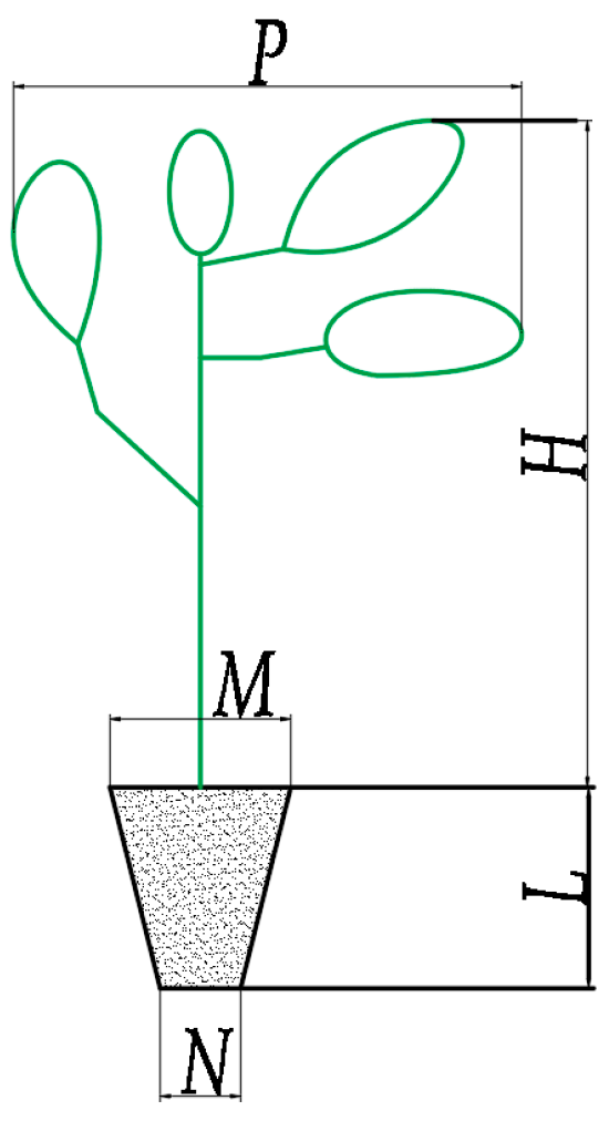
2.1. Physical Characteristics of Pepper Seedlings

Standard 50-cell pepper plug seedlings were studied. Dimension parameters were measured by experiment. The main morphological parameters are shown in Figure 1. Pot height was L = 50 mm, and it was an inverted, square prism. Its upper and lower sides were M = 48 mm and N = 20 mm. The values in this section are average values. Seedling height H = 167 mm, leaf width p = 110 mm, and moisture content of the pots μ = 40~75% were used in the experiment [18,19,20].
The compressive performance of plug seedlings refers to the ability of the pot to withstand external compressive force and is the basis for the design of the clamping force and clamping displacement of the seedling pick-up manipulator. The factors affecting the compressive properties are vegetable varieties, matrix composition of bowl body, moisture content, volume of soil bowl, gripper, etc. The test showed that the stress resistance of the pot decreased with the decrease in the pot volume and decreased with the increase in the moisture content of the pot, which had no significant relationship with the seedling [21,22,23]. With the increased compressive deformation of the pot during the clamping process, the compressive stiffness of the pot, i.e., the compressive strength, first decreased and then increased, and the curve was parabolic. Through a literature review and comprehensive analysis, it was concluded that the clamping capacity of a large bowl is about 6 mm–16 mm, and the clamping force is 4.97 N~14.15 N [24,25,26]. The above mechanical properties provided reference for the design and test in this paper.

2.2. Design Requirements for Manipulator

A manipulator needs to pick up the plug seedlings in good condition from the tray and place them in the planter. The design requirements are as follows: (1) Workspace requirements: the manipulator adopts vertical, downward movement close to the pot, and, inserted into the pot body for clamping, the four clamps are enclosed by the space to accommodate seedlings as much as possible, and clamping fingers in the process of downward movement touch the seedling stem and leaf as little as possible. (2) The clamping force requirements of the clamping fingers opening and closing are as follows: the clamping fingers are inserted into the pot with four contact points to a certain depth and stop moving downward. The clamping fingers are drawn inward and closed to clamp the pot and extract upward. During this process, the disturbance and damage to the matrix of the pot should be minimized, and the clamping force should be able to overcome the force to break away from the tray and be less than the limit yield force of the pot.

2.3. Design of Clamping Scheme

Seedling pick-up options are as follows: inserting while clamping, as shown in Figure 2c,d, or first inserting and then clamping, as shown in Figure 2a,b. By comparing Figure 2c,d with Figure 2a,b, it can be seen that the inserting while clamping mode has a larger scope of action and more obvious effect on pot substrate. The finger trajectory of the scheme is a composite of downward and inward motion. This paper used the combination of this theoretical model and Adams (2019.0.0-CL639814, Automatic Dynamic Analysis of Mechanical Systems, MSC Software Corporation, Newport Beach, CA, USA) simulation software for trajectory rationality analysis.
There are two insertion positions of the seedling clip finger. One is diagonally clipped, as shown in Figure 2a,c, the other is four-edge clipped, as shown in Figure 2b,d. The manipulator moves vertically downward with a 0° angle of finger insertion. In order to prevent the finger from touching the inner wall of the hole after reaching a certain depth, the insertion position of the finger should be a certain distance from the edge of the hole. The distance between the pointer and the center of the pot is q1 and q3 when clamping diagonally. The distance between the pointer and the center of the pot is q2 and q4 when four-edge clamping. Analysis showed that the former is greater than the latter, H3 > H4. So, diagonally clamping can obtain more matrix, and the clamping effect is better, so the diagonal clamping method was chosen.
In summary, inserting while clamping and diagonal clamping were selected, as shown in Figure 2c.

3. Design of Picking Up Seedling Manipulator

3.1. Working Principle of Picking Up Seedling Manipulator

The design of the seedling manipulator, as shown in Figure 3, was based on the above requirements. It is mainly composed of connecting plate, pneumatic cylinder, connection screw, cylinder fixing plate, intermediate moving block, connecting rod, bottom rack, clamping fingers for picking up seedlings, etc. Its driving force comes from the single-acting needle cylinder. The cylinder rod is fixed with the middle moving block. The cylinder rod drives the middle moving block up and down. The fingers pick up seedlings through the movement of the middle link.

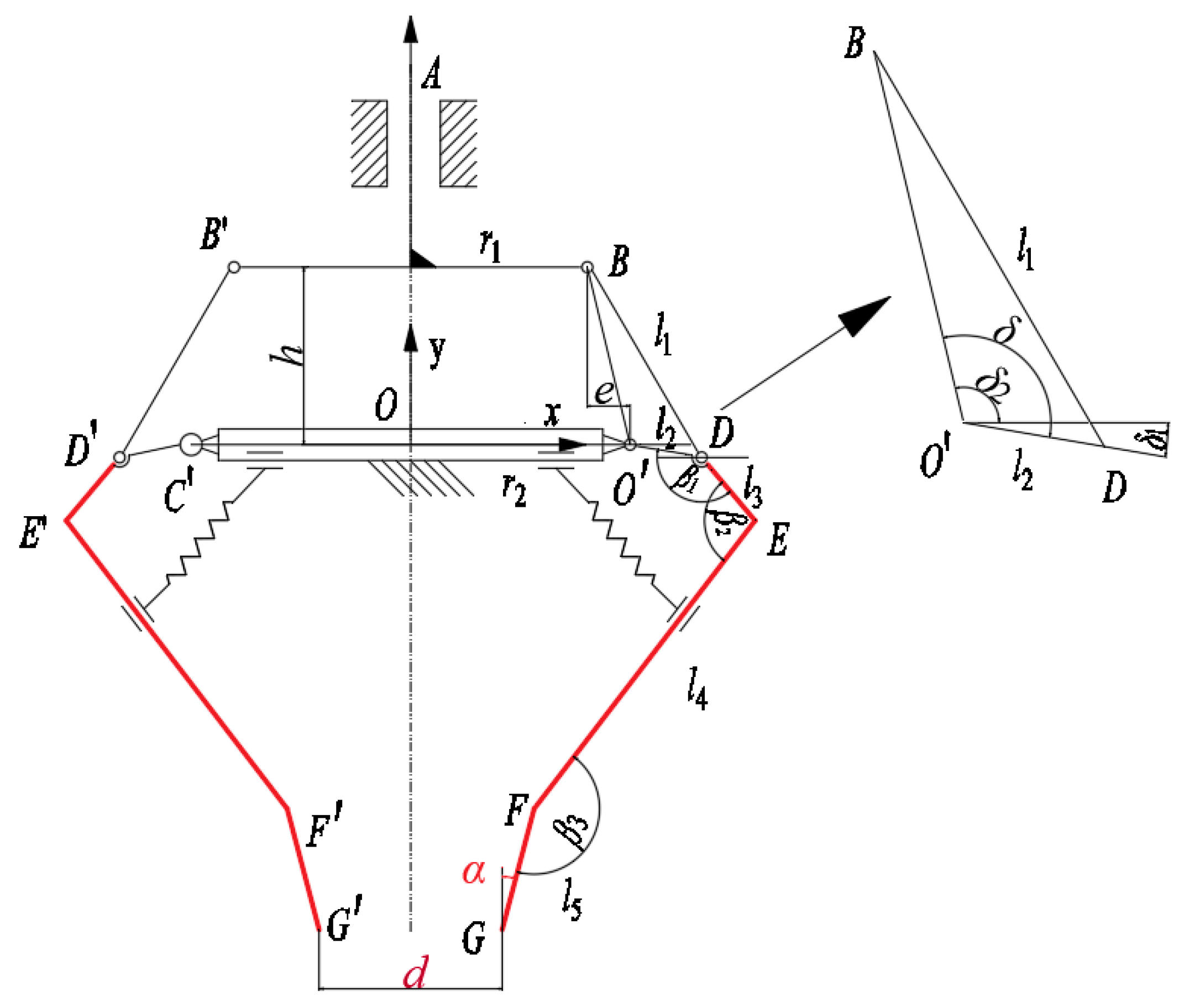
3.2. Analysis of Linkage Clamping Mechanism

In Figure 4, a motion diagram of the linkage clamping pick-up seedling mechanism is shown. It has a planar linkage with cylinder piston rod OA moving up and down as the motive power. It is an evolutionary form of the offset crank slider mechanism. The cylinder piston rod moves up and down, equal to BB’ moving up and down. Driven by the piston rod, the follower connecting rod BD moves. This transfers power to DEFG so as to realize the clamping action of the claws for picking up seedlings.
The degrees of freedom of the planar mechanisms are calculated as follows. Assuming that each component moves only in a plane, it has nine active components, each with three degrees of freedom. It has 13 low pairs, i.e., a moving pair A consisting of a cylinder block and a moving piston rod up and down and 12 rotational pairs B, C, D. Each plane low pair (rotating pair and moving pair) provides two constraints each. There is no high plane. So, there are (2 P1 + Ph) constraints. The degree of freedom Fd of the mechanism is 3 n-(2 P1 + Ph), so n = 9, P1 = 13, and Ph = 0 are brought into the formula to calculate Fd = 1.
The number of original motive parts of mechanism equals the degree of freedom, so this apparatus has the condition to determine the movement. The movement of the components is determined. The trajectory of the end point is determined. In order to obtain the required trajectory, it is necessary to carry out calculation analysis and parameters design.

3.3. Motion Mathematical Model of Linkage Clamping Mechanism

The four clamping fingers of the clamping mechanism have a uniform distribution of equal height in space. The motion of the four fingers is synchronous, so the two relative fingers are selected for analysis. Establishment of the Cartesian plane coordinate system is based on point O. Horizontal direction is the X-axis, vertical direction is the Y-axis.
The mathematical model of the linkage clamping mechanism is established to obtain the relationship between the h value and the position change of G point at the end of the pick-up claw and the equation between angle α of the FG segment relative to the ordinate.
The value of offset e is as follows:
e = r 2 r 1
The coordinate displacement equation of connecting rod end point B is as follows:
{ x B = r 1 y B = h
Point O′ is a fixed point, and its displacement equation is as follows:
{ x O = r 2 y O = 0
To obtain the desired end trajectory, angle δ should be more than 90°:
δ = arccos h 2 + e 2 + l 2 2 l 1 2 2 l 2 b
δ 2 = 180 ° arctan h e
Simultaneously, Equations (4) and (5) derive the following equation:
δ 1 = arccos h 2 + e 2 + l 2 2 l 1 2 2 l 2 b 180 + arctan h e
The connecting rod end point D is always located at the lower side of the horizontal coordinate, and the coordinate displacement equation is as follows:
{ x D = l 2 cos δ 1 y D = l 2 sin δ 1
The D point coordinate is known from l3 and β1, and the E point coordinate displacement equation can be obtained as follows:
{ x E = l 2 cos δ 1 + l 3 cos ( β 1 δ 1 ) y E = l 2 sin δ 1 l 3 sin ( β 1 δ 1 )
The E point coordinate is known, and the F point coordinate displacement equation can be obtained from l4 and β2 as follows:
{ x F = l 2 cos δ 1 l 3 cos ( β 1 δ 1 ) l 4 cos ( β 1 + β 2 δ 1 180 ) y F = l 2 sin δ 1 l 3 sin ( β 1 δ 1 ) l 4 sin ( β 1 + β 2 δ 1 180 )
The F point coordinate is known. From l5 and β3, the G point coordinate displacement equation can be obtained as follows:
{ x G = l 2 cos δ 1 l 3 cos ( β 1 δ 1 ) l 4 cos ( β 1 + β 2 δ 1 180 ) l 5 sin α y G = l 2 sin δ 1 l 3 sin ( β 1 δ 1 ) l 4 sin ( β 1 + β 2 δ 1 180 ) l 5 cos α
α = β 3 β 1 β 2 + δ 1 + 90
From the above analysis, the transfer relationship between the coordinate value of G point and D, E, F points is as follows:
{ x G = r 2 + x D + x E x F l 5   sin α y G = y D y E y F l 5 cos α
The clamping mechanism motion mathematical model can provide a theoretical basis for subsequent seedling trajectory calculation and simulation analysis.

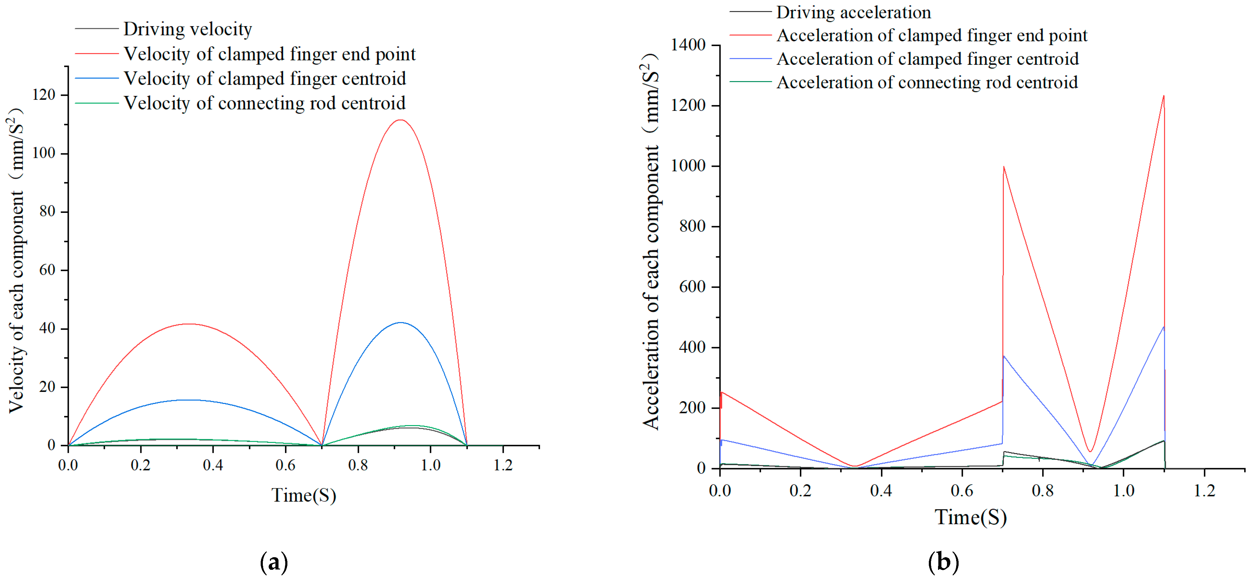
3.4. Speed and Acceleration Model of Mechanism

Assuming that the cylinder moves at a constant speed of v, the speed of t is:
h = h 0 v t
where h0 is the initial distance, mm.
The first and second derivative operations of the displacement equations are as follows, so we can obtain the velocity and acceleration equations of the end point G:
The velocity equation of point G is as follows:
{ x ˙ D = x ˙ D + x ˙ E x ˙ F l 5   cos α y ˙ G = y ˙ D y ˙ E y ˙ F + l 5 sin α
The acceleration equation of point G is as follows:
{ x ¨ D = x ¨ D + x ¨ E x ¨ F + l 5   sin α x ¨ G = x ¨ D x ¨ E x ¨ F + l 5 cos α
This part can provide a theoretical basis for the velocity and acceleration simulation analysis of each component of the mechanism.

3.5. Analysis and Design of Key Parameters

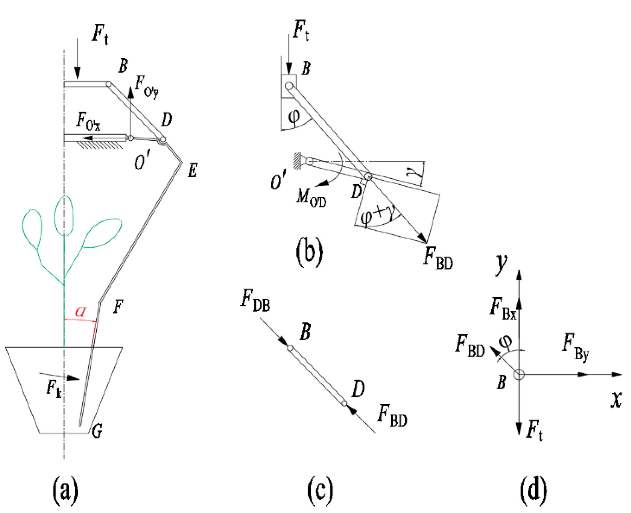
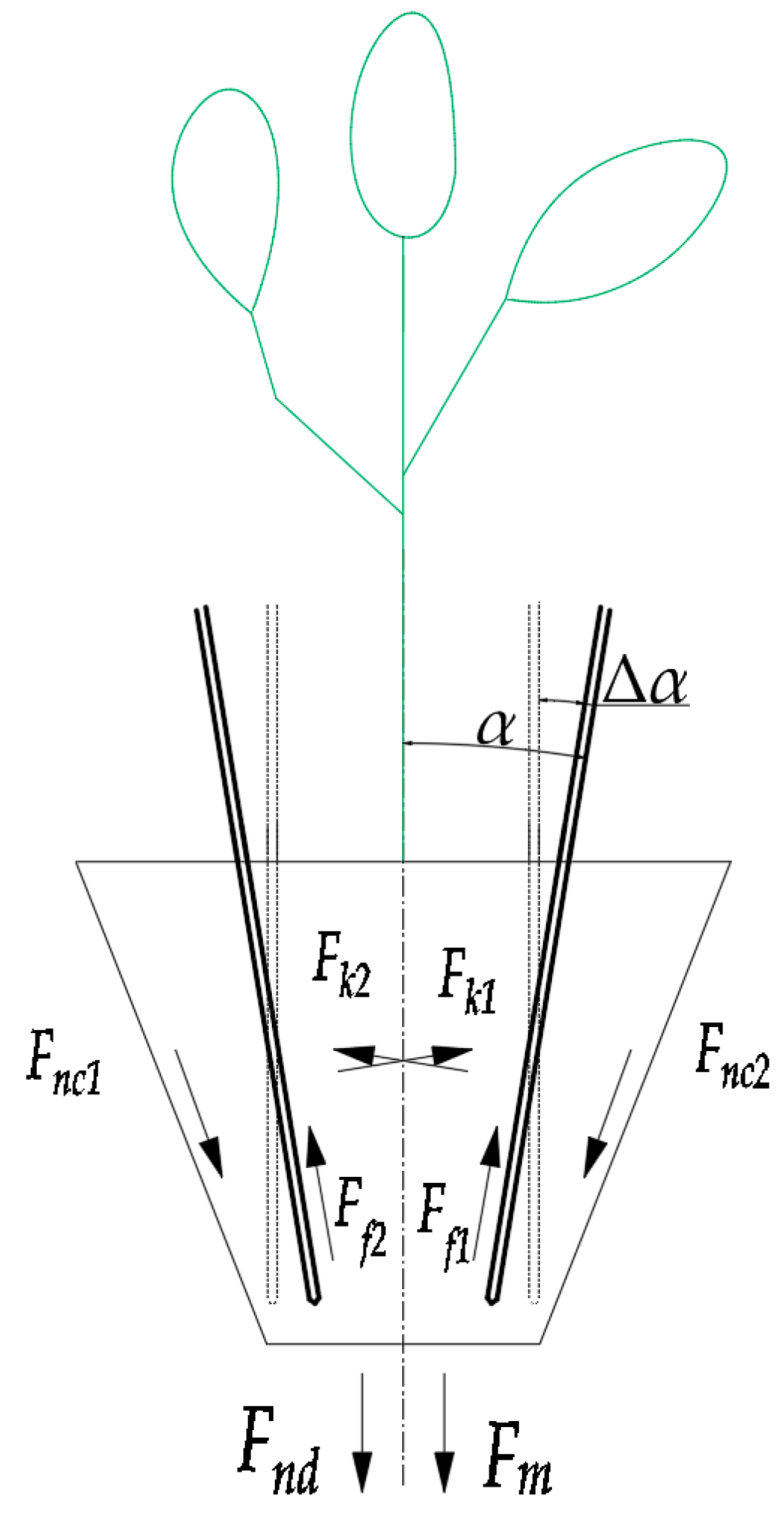
3.5.1. Force Analysis of Manipulator Mechanism

Force Transfer Analysis of Manipulator Mechanism

In order to achieve the better force transmission effect of the mechanism, the force analysis of the single finger of the manipulator is carried out, as shown in Figure 5. The force analysis is simplified in the same plane, and the multi-bar mechanism is assumed to be an ideal mechanism, that is, each member is regarded as a rigid body without weight, and the constraint is regarded as a smooth hinge.
The instantaneous force of the clamping pot by the seedling-taking manipulator is as shown in Figure 5a. The constraint between the O′ point and the fixed plate is a hinge. The binding force at O′ can be decomposed into orthogonal components FO′x and FO′y. Fk is the reaction force of the clamping finger end segment FG on the pot. The equilibrium equations of the above external forces in the x and y directions are, respectively:
{ F O x F k cos α = 0 F O y F t F k sin α = 0
We can solve these two equations simultaneously:
F k = F O x cos α
F t = F O y sin α F O x cos α
Since the gripping angle α is small, the gripping force F k F O x , and the thrust force F t F O y . Therefore, the O′ fulcrum is the balance fulcrum of the two forces, and this point is used as the mounting fixed point of the fingers. The stress of this fulcrum is relatively concentrated, and the strength can be appropriately considered in the design.
Mechanism forces are simplified to point to O′ by force analysis, as shown in Figure 5a,c,d. According to the resultant moment equilibrium, the relationship between the moment of couple MOD on the crank OD and the angle γ under the action of Ft can be obtained as follows:
F t + F B X + F D B cos φ = 0
F B D + F D B = 0
M O D F D B l 2 cos ( γ + φ ) = 0
Solving the above three equations, FBx in Equation (19) mainly comes from the friction at the hinge. Ignoring FBx, the following is obtained:
M O D = F t l 2 cos ( γ + φ ) cos φ
After analysis, if the crank is required to obtain a larger moment of couple, the greater the cos (γ + φ)/cos (φ), the better. In the design, φ can be made to take a larger value by parameter selection, and γ can be made to move in a range as small as possible when the mechanism moves so a better transmission effect can be obtained, and this is consistent with the conclusion of Equation (22). When the mechanism moves to γ = 0, the maximum moment of couple is obtained, which can be used as the design basis for improving the force transmission efficiency of the mechanism.

Force Analysis of the Interaction between Pot and Fingers

We assume that the component content in the pot is evenly distributed, and the four clipped fingers are uniformly stressed. The force between the finger and the pot can be simplified into two perpendicular planes. After the mechanical gripper fingers are inserted vertically into the seedling pot, the moment of lifting the pot seedling is as shown in Figure 6. The static equilibrium equation of the pot in the vertical direction is as follows:
4 F k 1 sin α F t 4 F f 1 cos α = 0
where Fk1 is the clamping force of a single clamping finger on the pot; Ff1 is the friction force between a single finger and the pot; and Fl is the pulling force required to extract the seedlings. Fl can be regarded as the resultant force of the pot adhesion force Fn and the gravity Fm of the tray, and Fn includes the adhesion force of the side Fnc and bottom of the four walls Fnd. The adhesion is mainly related to the condition of the root, the composition of the substrate, the material of the seedling plate, and the moisture content of the pot. Gravity Fm is mainly related to the size of tray, moisture content of pot, seedling age, and substrate composition. According to the existing literature, the pulling force of common vegetable seedlings, such as cucumber, tomato, and pepper seedlings, ranges from 0.97 to 5.6 N [5,25]. The unit of the above parameters is N.
The friction force of the fingers consists of two parts:
F f 1 = F f a + F f b = μ ( F k 1 + p 1 s 1 )
where μ is the static friction coefficient between the pot and the fingers’ material, which is 0.49~0.54. S1 is the actual contact area (mm2) of adhesion between a single finger and the pot. P1 is the adhesion pressure, which is 3000 Pa. Ff1 is the friction force of a single finger, N; Ffa is the slip friction force between pot soil and finger, N; and Ffb is the slip resistance between soil materials, N. Substituting Equation (24) into Equation (23) for analysis, the relationship model between the single clamping force and the clamping angle of the finger is as follows:
F k 1 = F l μ p 1 s 1 cos α 4 ( μ cos α + sin α )
The adhesion pressure and friction coefficient are related to the characteristics of the pot, and they are all constant values. According to Equation (25), the clamping force is directly and positively correlated with the drawing force. The relationship between the clamping force and the insertion angle is complicated. If Ffb is ignored, the larger the clamping angle α is, the smaller the clamping force required. If the Ffb is not ignored, the larger the Ffb, the better, that is, improving the adhesion pressure and the contact area between the finger and the pot can reduce the required clamping force. S1 is directly proportional to the depth of insertion and the width of the finger. When S1 = 30 × 10 × 2 = 600 mm3, pS1 = 1.8 N. Then, the clamping force of a single finger is about 2.8 N, and the resultant force of the four fingers is 11.2 N, in the range of 4.97–14.15 N, as described in Section 2.1. The selected single-acting needle cylinder model is CJP2B6-10, the cylinder diameter is 6 mm, the design stroke is 10 mm, and the output force of the cylinder is 15.9 N when the air source pressure is 0.7 MPa.

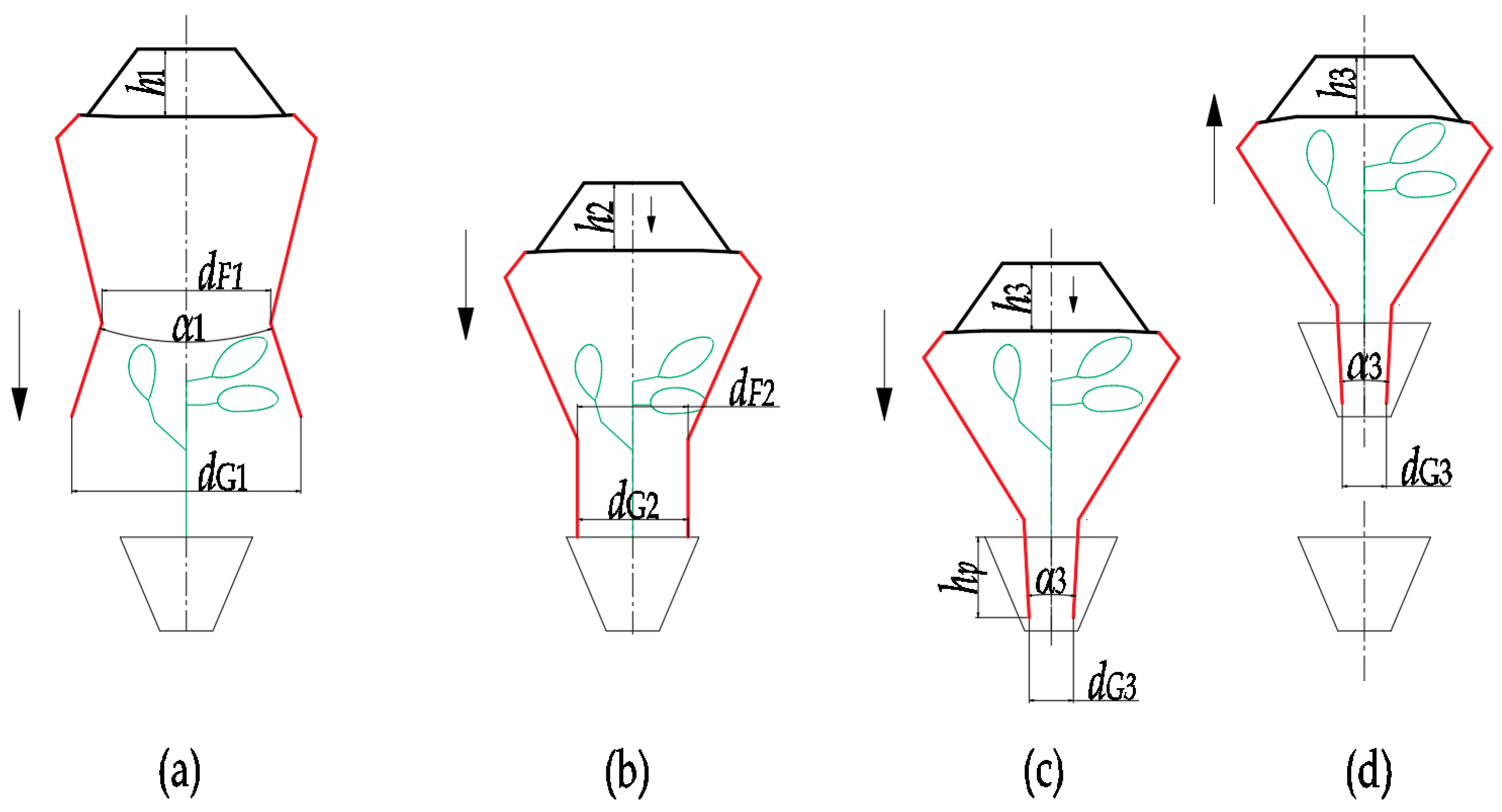
3.5.2. Structural Parameters Design of Manipulator
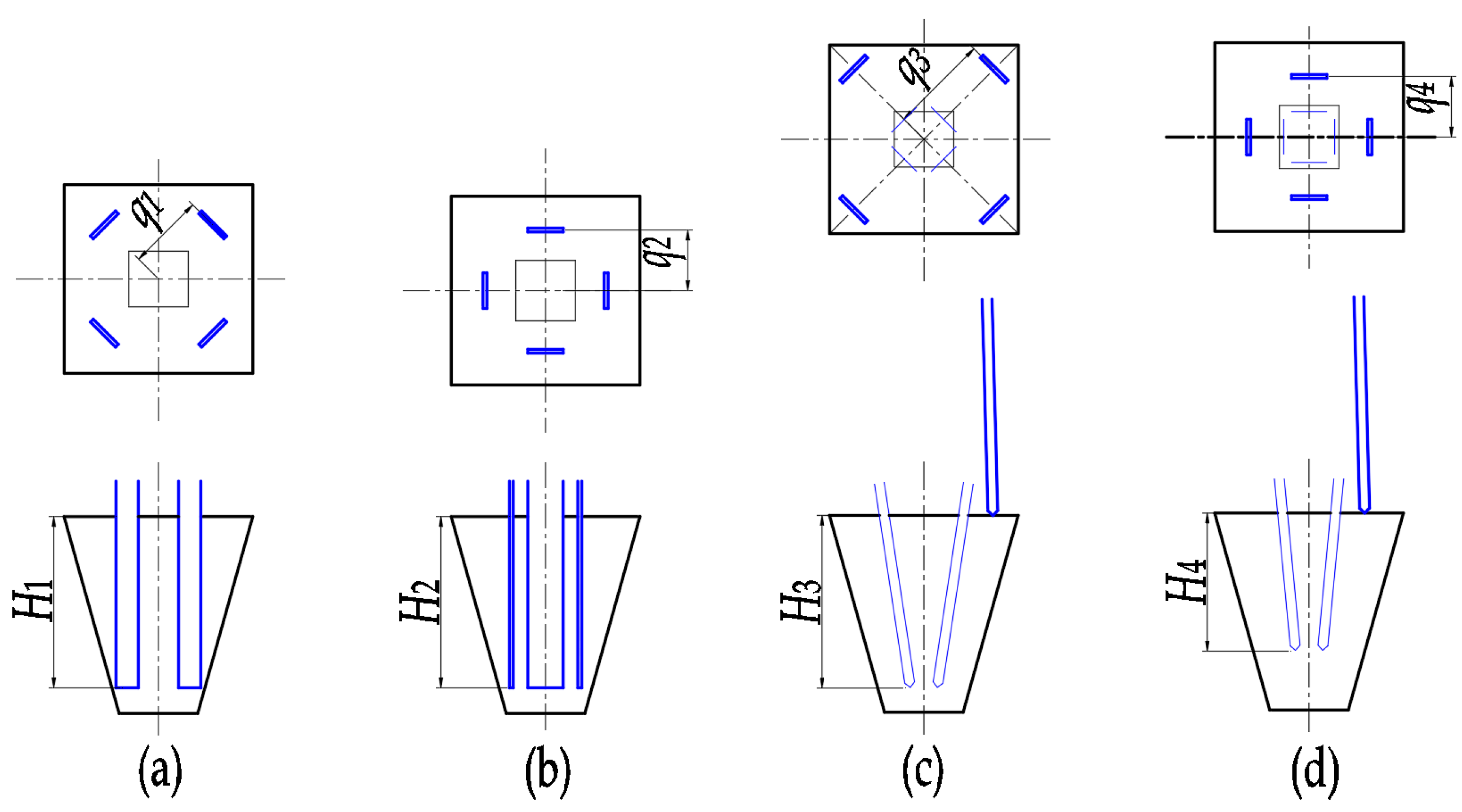
From the analysis of the above mathematical model parameters, it can be seen that h is the key motion parameter, and the relationship between its value and the change of the end trajectory is the core problem. A complete four-finger pick-up pot operation is shown in Figure 7 and can be described as follows:
(1)
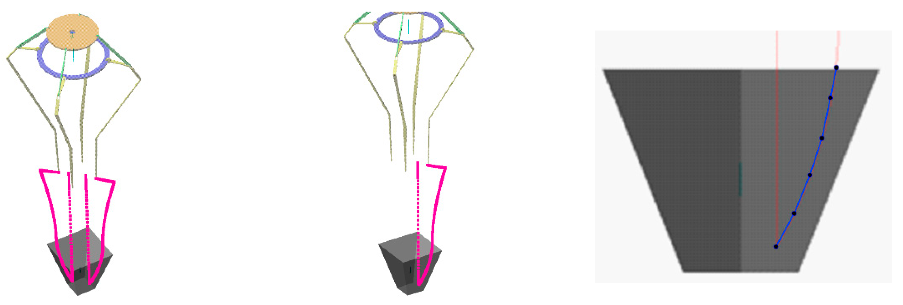
At the beginning of the pick-up period, the pick-up manipulator keeps its fingers open. By setting the relative displacement between the middle moving block and the bottom frame as h1, the preset opening range is obtained. The initial angle between the fingers is α1, and dG1 > dF1 so as to avoid damaging the leaves as much as possible, as shown in Figure 7a;
(2)
Manipulator feeds are close to the tray seedling pot along the vertical direction. The four fingers are perpendicular to the upper surface of the tray before the manipulator reaches the picking point. The relative distance between the two fingers is dG2 = dF2 = d0. At this point, the relative displacement between the middle moving block and the bottom frame is h2, as shown in Figure 7b;
(3)
The manipulator continues to move vertically downward, and clamping fingers are inserted into the matrix, wrapped in the root, and clamped at an inserting depth of hp. At this point, the relative displacement between the middle moving block and the bottom frame is h3. The opening of the angle between the fingers is upward, the angle is α3, dG3 < dF3, and this is the clamping state, as shown in Figure 7c;
(4)
The four fingers keep the clamping state, and the manipulator lifts the pot seedling vertically, as shown in Figure 7d. In addition to overcoming the gravity of the pot seedling, the extraction force of this process is to remove of the adhesion force between the matrix block and the plug.
In this process, h is the input variable, and h1 is the initial value. h1 is reduced to h2 for the time point for contact with the bowl. In this process, h1 > h2 > h3. The output variable is the end point edge length dG and the angle between the end of the manipulator and the two fingers α. The constraint conditions of parameter size for analyzing the success of seedlings are as follows:
{ ( d G 1 d F 1 d F 1 P d G 2 = d F 2 α 2 = 0 d F 2 2 M h p < L d G 3 d F 3 )
According to the morphological characteristic parameters of the pot in Section 2.1, in order to make the G point at the end of the seedling claw inserted into the pot downward along the inner wall of the hole, the d value is theoretically slightly less than 50 mm, and the safety value is 45 mm. According to the conclusion obtained in Section 3.5.1. the parameter φ and the clamping angle α take larger values.
Based on the above constraint conditions of the manipulator design for seedling pick-up, a set of structural parameters satisfying the requirements of the seedling pick-up process is obtained through calculation analysis and computer-aided design verification. The values are shown in Table 1.
Using this group of parameters, the calculation shows that, when h1 = 32.35 mm, as in Figure 7a, the fingers open to the maximum, open amplitude dF1 = 76.72 mm, and angle α1 = 10.18°. This is the state of avoiding touching the seedling.
When h2 = 30.15 mm, as in Figure 7b, the end of the clip finger just touches the pot. The opening amplitude is dF2 = 47.79 mm, and the angle is α1 = 0°, which is prepared for insertion.
When h3 = 28.75 mm, as in Figure 7c,d, the ends of the fingers tighten inward to the limit, dG3 = 17.46, and α3 = 10.74°, which is the extraction point.
The above verification shows that the parameters in Table 1 meet the requirements of the seedling pick-up constraint.

3.6. Trajectory Analysis of Finger End

Based on the kinematic model formula of the mechanism derived above and a set of designed parameter sizes, seven points at the end point are calculated. They are connected to a red trajectory curve in the pot, as shown in Figure 8.
Position (1) in the graph is the state of the initial maximum opening angle and the position of the contact soil when received to (2). Fingers insert inside the pot and clip to the final position (7) to stop, keep still, and lift up vertically to finish picking up the seedlings. Starting from touching soil, h is pushed from 32.35 mm to 28.75 mm under cylinder motion. The cylinder travels 3.6 mm, and the corresponding manipulator should move 45 mm downward. This trajectory can complete the seedling pick-up action.

4. Motion Analysis of Virtual Prototype Simulation

In order to verify the results of the above theoretical calculation and further analyze the motion performance of the seedling pick-up manipulator and provide the basis for the bench test, a virtual prototype simulation motion analysis was carried out.

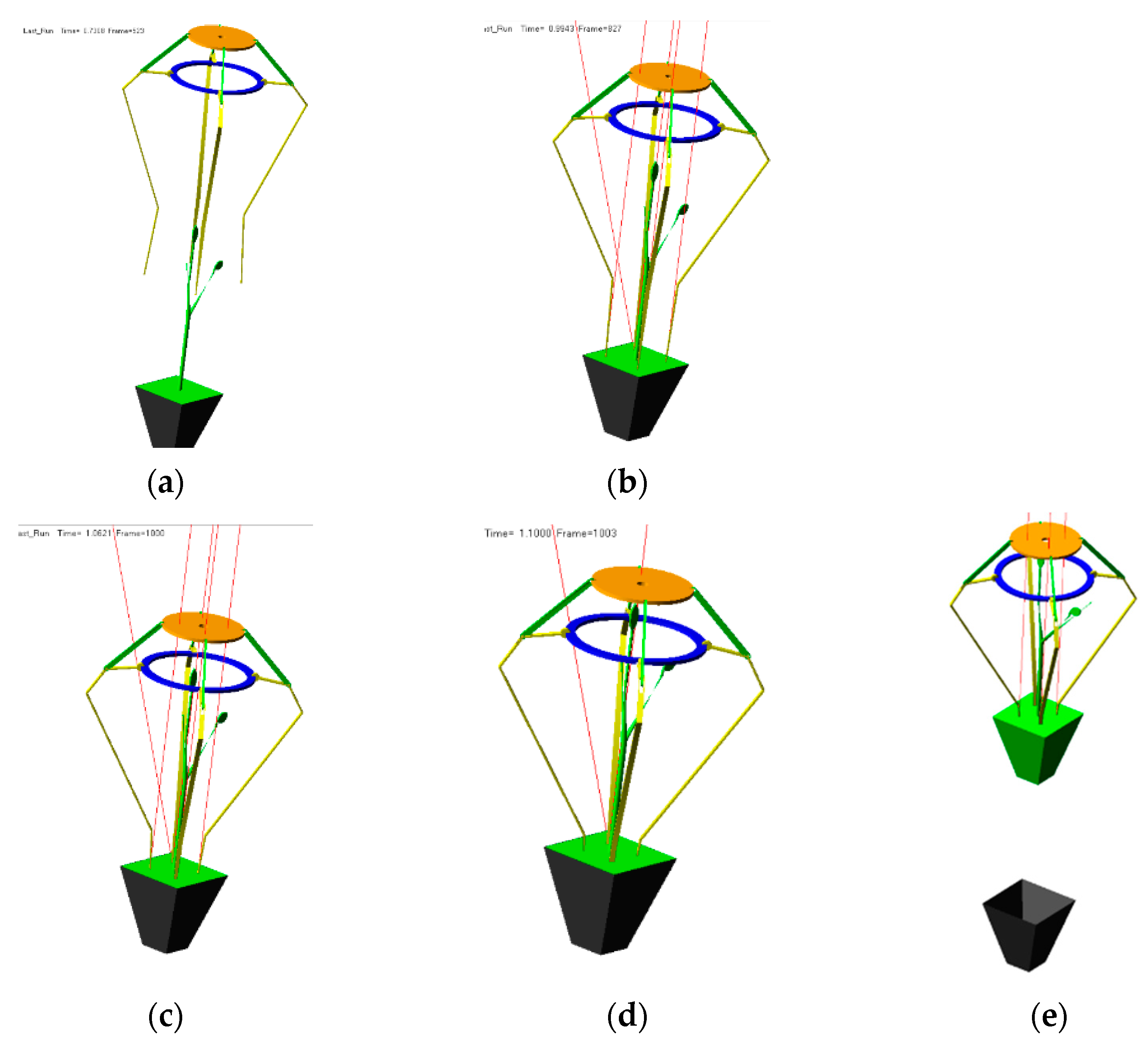
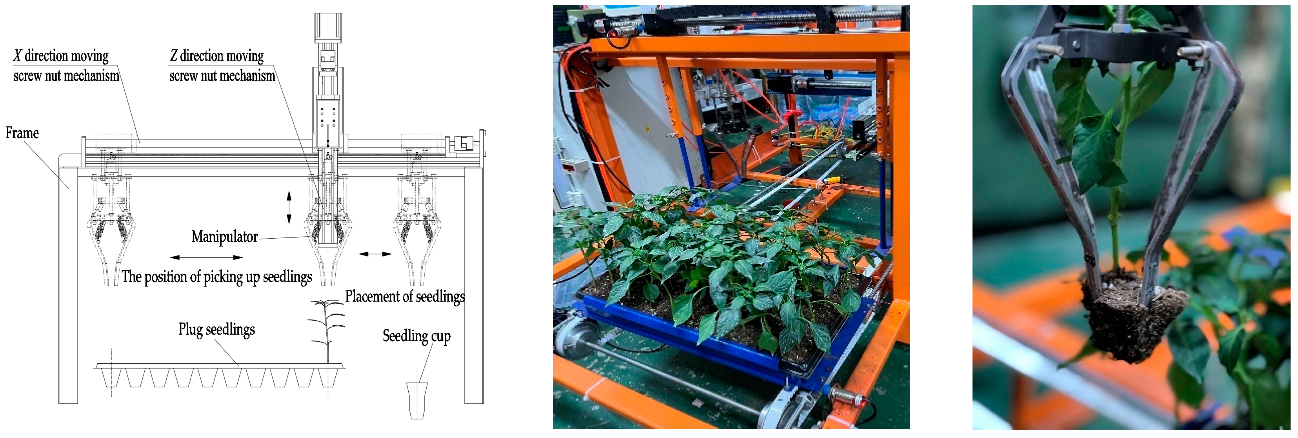
4.1. Virtual Prototype Model

The mathematical model of Section 3.3 was used as the basis of mechanism parameterization, and the results of the Section 3.5.2 manipulator mechanism parameter design were used. The model of each part was simplified by using SolidWorks according to the size in Table 1. The manipulator assembly was imported into Adams to add simulation parameters such as quality attributes, constraints, and contact force, etc.
According to the relative motion and constraint conditions between each part of the seedling pick-up manipulator, the manipulator as a whole is relative to the ground, the manipulator as a whole is relative to the seedling (seedling50), and the seedling relative to the pot is moving in a straight line up and down. Four fingers (finger1, finger2, finger3, finger4) relative to the bottom frame (fix), four fingers relative to the four connecting rods (rod1, rod2, rod3, rod4), and the middle moving block (drive) relative to the four connecting rods have rotating motion. The motion pair was added, as shown in Table 2, and the virtual prototype model was established, as shown in Figure 9.

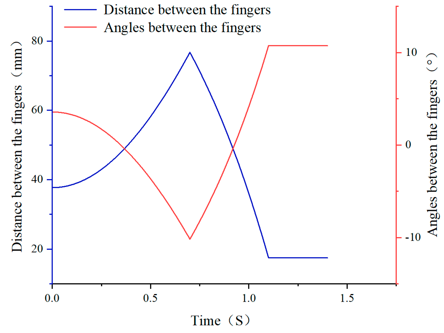
4.2. Motion Simulation Analysis and Verification

The motion form of the driving source was defined by the IF velocity function. The initial state of the assembly model imported by the manipulator into Adams was the state of closure, and the end point was 100 mm away from the upper surface of the pot. It was necessary to give the cylinder piston drive speed to move the middle moving block drive straight to the right position and make the initial state of the manipulator open, stay away from seedling leaves, and start picking up seedlings. The driving force of the manipulator comes from the middle moving block (drive) and the vertical downward movement of the manipulator, so the driving force was added, as shown in the last column of Table 2, and the motion equations of the drive source are shown in Table 3. After repeated debugging, the duration of a seedling picking cycle was 1.2 s. The required action was as shown in Figure 10a–e. The state process was as follows: a. Finger initial state is open, staying away from the seedling and closing down; b. Contact time between finger and pot; c. Clamping the bowl while the fingers are down; d. Fingers reach the required depth; e. Seedlings are extracted from plugs. The process achieves the seedling picking effect analyzed in Section 2.2.
The simulation steps were set to 1000, and the curves of the amplitude and angle of the end position are shown in Figure 11. It can be seen that the manipulator completed the motion process of first inserting, then inserting and clamping, and, finally, clamping. When t1 = 0.7 s, h1 = 32.3469 mm, the distance between the two fingers was the maximum, namely, dG1 was 76.7210 mm, and the angle α1 was the maximum 10.1801°. When t2 = 0.9268 s, h2 = 30.5115 mm at the contact time between the tip of the open finger and the upper surface of the pot, the distance between the two fingers was 47.7853 mm, and the angle α2 = 0°. When t3 = 1.100 s, h3 = 28.7525 mm in a clamping state, the relative distance between the two fingers dG3 was 17.4573 mm, and the angle was α3 = 10.7414°. The above data are consistent with the calculated value of Chapter 3.5.2. From the contact pot to the clamping end, the unilateral motion amplitude was 15.164 mm, which meets the requirements of the pot characteristics described in Section 2.1 [27,28,29,30].
In the process of seedling extraction, the movement trajectory of the finger end segment was as shown in Figure 12. The red curve is the simulation trajectory, and the blue curve is the calculated fitting trajectory. It is basically consistent with the trajectory curve of Figure 8, which meets the working requirements for clamping the seedling while inserting.
The motion form of the driving source defined by the IF function was adopted. The cylinder piston moves at a constant speed, and the speed changes abruptly, which is not in line with the actual working conditions. In order to further analyze the variation law of the speed and acceleration of each component, the STEP function was adopted for a simulation based on the above data, and the motion function is shown in Table 4.
The STEP function was used to analyze the motion and clamping of the cylinder, and the STEP motion was set on the middle moving block to simulate the power provided by the cylinder. In the process of taking the seedling, the cylinder drives the piston to perform a reciprocating motion, which is first accelerated, then decelerated and stopped and then first accelerated, then decelerated and finally stopped in the reverse direction.
The change curves of the velocity and acceleration at the centroid point of the other components and the end point of the pinching finger were obtained by simulation, as shown in Figure 13a,b. It can be seen that the movement velocity of the connecting rod and the driving block change little, indicating that the movement amplitude of the connecting rod is relatively small during the whole process of seedling harvesting. The center of mass of the pinching finger changes synchronously with the velocity of the end point of the pinching finger, and the velocity of the end point of the pinching finger is amplified, so the velocity of the end point of the pinching finger contacting the pot body is the largest. At 0.9268 s, when the pinching finger starts to contact the pot body, the velocity of the end point of the pinching finger reaches the maximum.
The movement acceleration of the connecting rod and the driving block change little, indicating that the inertia and impact of the movement are relatively small in the whole process of taking seedlings. The center of mass of the pinching finger and the velocity of the pinching finger end point are roughly synchronized, and the acceleration of the end point is much larger, especially at the moment when the pinching finger begins to approach the cave disc seedling at 0.7 s and the late extraction period after the pinching finger at 1.1 s. The acceleration increases significantly at these two moments, indicating that the inertial impact is large.

5. Picking Seedling Experiment

5.1. Test Conditions and Methods

To verify the operational performance of the manipulator, an experiment was carried out in the College of Engineering, Huazhong Agricultural University, from 20 June 2022 to 25 June 2022. The experimental object was “Zhongnong Lvheng Line Pepper 363”, and the seedlings were bred in the greenhouse of Tefeng Seedling Base in Shouguang City, Shandong Province. The size of the plug tray was a standard 50-hole seedling tray. The substrate was made of peat, vermiculite, and perlite with a mass ratio of 3:1:1. The seedling age was 40 days. The test equipment was one set of a trial-produced manipulator, transplanter bench developed by the research group, electronic balance, etc.
According to the analysis results described in Section 3.5.1 and Section 3.5.2, the gaskets at the upper and lower ends of the cylinder piston were adjusted to make the change range of the H value meet the requirements; the stroke should be greater than 3.6 mm, and the cylinder pressure should be set as 0.7 MPa and debugged to make the manipulator work properly. The manipulator was installed on the transplanter bench of the research group, as shown in Figure 14. The horizontal movement and up and down of the manipulator were handled by two sets of screw nut mechanisms driven by stepper motors, and the pneumatic system of the platform drove the clamping cylinder of the manipulator. The debugged transplanter bench enabled the manipulator to move according to the specified route and speed and cooperated with the closing and opening of the cylinder so as to complete the process of clamping seedlings, picking up seedlings, and putting seedlings with the designed action. The manipulator moved to the top of the target position in an open state, moved vertically down to the top surface of the pot 16 mm, and then inserted into the pot 45 mm deep while clamping. After the clamping was completed, it moved vertically up to a safe height of 200 mm. The manipulator moved the seedling to the desired position point, the cylinder was closed, and the mechanical finger opened to put the seedling in the specified position.

5.2. Experiment Factors and Levels

Seedling age, pot moisture content, and seedling pick-up speed all affect the success rate of transplanting. Pot moisture content affects the pot body weight and mechanical properties of the seedlings, which have a certain influence on transplanting. The pot moisture content of pepper plug seedlings is commonly between 40% and 75%, so 45%, 58%, and 71% were the moisture content of the three levels; before the experiment, the water content was controlled at low, medium, and high levels by watering amount, and the test was carried out when the pot was evenly absorbed. According to the repeated adjustment of the manipulator movement speed and acceleration and the cylinder coordination action, the duration of one seedling pick-up cycle was 3.75 s, 3 s, and 2.5 s, respectively, and the corresponding seedling pick-up frequency was 16 plants·min−1, 20 plants·min−1, and 24 plants·min−1. The clip fingers were made of metal Q235A (in the following article, it is referred to as carbon steel) and nylon 7100. Factors and levels are shown in Table 5; it was a three-factor test, where two factors were at level 3 and one factor was at level 2, assuming that the metal was used as a good level of the finger material to repeat once, and using the quasi-level method made the factor into level 3 [31,32].

5.3. Test Evaluation Index

The test indexes were pot damage rate and seedling pick-up success rate. The pot damage rate is the ratio of the mass of the matrix soil scattered to the total mass in the process of picking up and placing seedlings. During the experiment, the seedlings were removed completely and stored in trays in an orderly manner. At the end of the experiment, all the collected, scattered soil was weighed, and only the pot body was weighed, and the seedlings were cut off (ignoring the influence of seedling roots on the pot body weight). The seedlings and substrates in the tray were weighed by an electronic balance (JJ200 model, accuracy 0.01 g), which was calculated as the mass ma that was not lost in the experiment. The lost matrix was collected and weighed, and the mass was recorded as mb [5,33]. The success rate of seedling pick-up was the probability of successful seedling pick-up and release by the manipulator according to the requirements. The following situations were regarded as seedling taking failure: the seedlings are not picked up, the matrix soil which falls in the process of seedling pick-up and the mass of the scattered matrix soil is more than 1/3 of the total mass. The calculation formula is as follows:
S 1 = m b m b + m a
S 2 = n a n t
where S1 is the pot damage rate, %; S2 denotes the success rate of seedling pick-up, %; na is the number of successful seedlings picked up; and nt is the total number of seedlings picked up.

5.4. Analysis of Test Results

An L9 (34) orthogonal test was carried out, and the test results are shown in Table 6. Seedlings were picked up 20 times for each test number, and the results were averaged [4]. The results show that the total success rate was 96.11%, the total pot damage rate was 4.28%, and the damage rate ranged from 2.62 to 7.78%. The damaged parts were mainly concentrated in the edge and upper end of the pot body, where the developed degree of the root system was relatively low, and the main force point of the manipulator was concentrated. The main reasons for the failure of seedling pick-up and pot damage were as follows: (1) the growth of some acupoint disc seedlings was relatively slow, the disc root was weak, and the pot body cohesion was low. For seedlings with good growth conditions, the device had higher reliability. (2) The processing and assembly errors of the seedling pick-up device caused the deviation of the pick-up point, and some seedlings grew at a tilt, so the distribution of the main stem deviated from the center of the pot. (3) The mass of the pot with low water content was smaller, and the aggregate pressure in the pot increased first and then tended to be stable with the increase in water content [12], so the seedling pick-up effect was better when the water content was low.
The factors affecting the success rate of seedling pick-up and the damage rate of pot body in the primary and secondary order were finger material, moisture content of pot body, and seedling pick-up frequency. In this experiment, the optimal parameter combinations of pot damage rate and seedling pick-up success rate were carbon steel, low pot moisture content, and seedling frequency of 20 plants·min−1.
Parameter ANOVA is shown in Table 7, and the ANOVA results of the three factors about pot damage rate were all p < 0.0001. The three factors had significant influence on the pot damage rate. In the analysis of variance on the success rate of seedling pick-up, the factors of moisture content of pot body and finger material were p < 0.01, indicating that the moisture content of pot body and finger material had very significant impact on the success rate of seedling pick-up, and the factor of frequency of seedling pick-up was p < 0.025, which had a significant impact on the success rate of seedling pick-up.
The optimal result set obtained from the test results was as follows: carbon steel, low moisture content, and 20 plants·min−1 seedling pick-up frequency, which was used to carry out the seedling pick-up validation test. The average value of 50 plants was obtained, the pot damage rate was 1.98%, and the success rate of seedling pick-up was 98%, which verified the reliability of the manipulator. In the experiment, one seedling failed to be picked up due to the weak growth of the plug seedling, skewed stem, and underdeveloped root system, so it fell off when it was clamped. The seedling pick-up manipulator developed in this paper has some advantages in seedling pick-up success rate and pot damage rate; it has good clamping effect and good seedling pick-up performance.

6. Conclusions

(1) According to the characteristics of the pepper plug seedling and the requirements for picking up seedlings, this paper determined that the clamping scheme is edge inserting, edge clamping, and diagonal clamping and designed an open-and-close plug seedling picking manipulator with four fingers. Based on the constraints of the best force transfer efficiency and low loss, the optimal parameters and the trajectory curve of the finger end in the pot body were calculated;
(2) The kinematics parameters of Adams were analyzed and verified, and the motion forms of the driving source were defined by using IF and STEP velocity functions, respectively. The manipulator opened to avoid seedlings, approached vertically downward to the pot, inserted into the pot, and clamped and lifted the pot body substrates. The end point trajectories obtained by motion simulation were basically consistent with those obtained by theoretical calculation. The change curve analysis of the velocity and acceleration of the components of each mechanism showed that the velocity and acceleration of the end point of the finger changed greatly, so the inertial impact was large, which was helpful for clamping the pot body;
(3) The experiment of picking up seedlings was carried out, and the pot moisture content (A), seedling frequency (B), and finger material (C) were taken as the test factors. The experimental results showed that the moisture content and the frequency of seedling pick-up rate has highly significant effect; when the moisture content was low, the frequency of seedling picking was 20 plants·min−1, and the clamping finger material was carbon steel, the damage rate of the pot body was 1.98%, and the success rate of picking up seedlings was 98%. The manipulator has good performance in picking seedlings.
The operation effect of the manipulator under the optimal parameter combination meets the production needs. The next step is to install the manipulator into the transplanter and coordinate the manipulator with the planting mechanism.

Author Contributions

Conceptualization, N.Z., G.Z. and H.L.; data curation, N.Z.; formal analysis, N.Z. and W.L.; investigation, W.L.; methodology, N.Z.; project administration, G.Z.; funding acquisition, G.Z.; software, N.T.; supervision, G.Z.; visualization, H.L. and J.W.; Writing—original draft preparation, N.Z.; Writing—review and editing, G.Z., J.W. and N.T. All authors have read and agreed to the published version of the manuscript.

Funding

This work was financially supported by the Project of Scientific and Technological Innovation Team for the Excellent Young and Middle-Aged in Hubei Province (T201934), China Agriculture Research System of MOF and MARA, grant number CARS-24-D-02. The funder is Zhang Guozhong.

Institutional Review Board Statement

Not applicable.

Data Availability Statement

The data presented in this study are available on demand from the first author at [email protected].

Conflicts of Interest

The authors declare no conflict of interest.

References

  1. Wen, Y.S.; Zhang, J.X.; Yuan, T. Current situation and analysis of automatic pick-up technology for vegetable plug seedlings. J. China Agric. Univ. 2021, 26, 128–142. [Google Scholar]
  2. Zhang, N.; Zhang, G.Z. Research status and prospect of rice planting mechanization. Hubei Agric. Sci. 2020, 59, 5–10. [Google Scholar]
  3. Hu, Q.L.; Zhang, Q.S.; Li, X.Z. Design and parameter analysis of seedling collection device of rapeseed substrate block seedlings transplanter machine. Trans. Chin. Soc. Agric. Eng. 2021, 37, 18–27. [Google Scholar]
  4. Feng, S.J.; Wu, M.L.; Yan, B.; Quan, W. Design and test of eject lifting type pot seedling detaching device. Trans. Chin. Soc. Agric. Eng. 2020, 36, 50–58. [Google Scholar]
  5. Ma, X.X.; Li, H.; Cao, W.B. Optimization and experiment of working parameters of automatic seedling picking device for tomato seedlings transplanting. Trans. Chin. Soc. Agric. Eng. 2020, 36, 46–55. [Google Scholar]
  6. Liao, Q.X.; Zhang, Z.; Hu, Q.L. Design and trajectory analysis of pneumatic picking-up mechanism for rape paper pot seedling. Trans. Chin. Soc. Agric. Mach. 2017, 48, 70–78. [Google Scholar]
  7. Xu, C.L.; Lv, Z.J.; Xin, L. Optimization design and experiment of full-automatic strawberry potted seedling transplanting mechanism. Trans. Chin. Soc. Agric. Mach. 2019, 50, 97–106. [Google Scholar]
  8. Ryu, K.H.; Kim, G.; Han, J.S. Automation and emerging technologies: Development of a robotic transplanter for bedding plants. J. Agric. Eng. Res. 2001, 78, 141–146. [Google Scholar] [CrossRef]
  9. Choi, W.C.; Kim, D.C.; Ryu, I.; Kim, K.U. Development of a Seedling Pick-up Device for Vegetable Transplanters. Trans. ASAE 2002, 45, 13–19. [Google Scholar]
  10. Islam, M.N.; Iqbal, M.Z.; Ali, M. Kinematic Analysis of a Clamp-Type Picking Device for an Automatic Pepper Transplanter. Agriculture 2020, 10, 627. [Google Scholar] [CrossRef]
  11. Li, H.; Ma, X.X.; Cao, W.B. Design and experiment of seedling picking mechanism by stem clipping for tomato plug seedling. Trans. Chin. Soc. Agric. Eng. 2020, 36, 39–48. [Google Scholar]
  12. Tong, J.H.; Shi, H.F.; Wu, C.Y. Simulation and test of seedling pot grabbing by spade end-effector. Trans. Chin. Soc. Agric. Mach. 2019, 50, 107–116. [Google Scholar]
  13. Jiang, Z.H.; Jiang, H.Y.; Tong, J.H. Optimal design of end-effector on automatic plug seedling transplanter. J. Zhejiang Univ. Eng. Sci. 2017, 51, 1119–1125. [Google Scholar]
  14. Liang, X.F.; Xiao, X.Z.; Zhu, Y.H. Design and experiment on pot-seedling supplementing end-effector for vegetables in cotyledon phase. Trans. CSAE 2018, 34, 49–57. [Google Scholar]
  15. Xie, S.Y.; Yang, S.H.; Liu, J. Development of the seedling taking and throwing device with oblique insertion and plug clipping for vegetable transplanters. Trans. Chin. Soc. Agric. Eng. 2020, 36, 1–10. [Google Scholar]
  16. Han, L.H.; Mao, H.P.; Yan, L. Pincette-type end-effector using two fingers and four pins for picking up seedlings. Trans. Chin. Soc. Agric. Mach. 2015, 46, 23–30. [Google Scholar]
  17. Han, B.; Shen, D.S.; Guo, C. Design and experiment of adjustable end-effector of cabbage seedings. Trans. Chin. Soc. Agric. Mach. 2019, 50, 111–120. [Google Scholar]
  18. Wang, M.M.; Song, J.N.; Liu, C.L. Design and experiment of crank rocker type clamp seedlings mechanism of vegetable transplanter. Trans. CSAE 2015, 31, 49–57. [Google Scholar]
  19. Han, C.J.; Xiao, L.Q.; Xu, Y. Design and experiment of the automatic transplanter for chili plug seedlings. Trans. CSAE 2021, 37, 20–29. [Google Scholar]
  20. Han, C.J.; Zhao, X.W.; Guo, H. Experimental study on determination of pepper plug seedling morphological characteristic. Chin. Agric. Mech. 2015, 37, 191–193. [Google Scholar]
  21. Ma, Y.F.; Wang, W.B.; Feng, J.A. Experimental study on compression properties transplanted tomato plug seedlings pot. Chin. J. Agric. Mach. Chem. 2020, 41, 64–71. [Google Scholar]
  22. Wang, Y.; Chen, J.N.; Wu, J.W. Mechanics property experiment of broccoli seedling oriented to mechanized planting. Trans. Chin. Soc. Agric. Eng. 2014, 30, 1–10. [Google Scholar]
  23. Hu, J.; Han, L.H.; Wen, Y.F. Mechanical properties of different vegetable plug seedlings as related to automatic transplanting. J. Agric. Mech. Res. 2018, 40, 132–136. [Google Scholar]
  24. Miao, X.H.; Mao, H.P.; Han, L.H. Analysis of influencing factors on force of picking plug seedlings and pressure resistance of plug seedlings. Trans. Chin. Soc. Agric. Mach. 2013, 44, 27–32. [Google Scholar]
  25. Han, L.H.; Mao, H.P.; Hu, J.P. Experiment on mechanical property of seedling pot for automatic transplanter. Trans. Chin. Soc. Agric. Eng. 2013, 29, 24–29. [Google Scholar]
  26. Wang, Y.Y.; Yu, H.Y. Experiment and analysis of impact factors for soil matrix intact rate of manipulator for picking-up plug seedlings. Trans. Chin. Soc. Agric. Eng. 2015, 31, 65–71. [Google Scholar]
  27. Hu, J.P.; Pan, J.; Chen, F. Simulation and Optimization Design of Finger-clamping Seedling Picking Claw Based on EDEM-RecurDyn. Trans. Chin. Soc. Agric. Mach. 2022, 53, 75–85, 301. [Google Scholar]
  28. Shen, T.H.; Feng, J.A.; Wang, W.B. Virtual design and parameter optimization of the transplanter’s end-effector based on ADAMS. J. Mach. Des. 2019, 36, 46–51. [Google Scholar]
  29. Tong, J.H.; Meng, Q.X.; Gu, S. Design and experiment of high-speed sparse transplanting mechanism for hydroponics pot seedlings in greenhouses. Trans. Chin. Soc. Agric. Eng. 2021, 37, 1–9. [Google Scholar]
  30. Jin, X.; Li, S.J.; Yang, X.J. Motion analysis and parameter optimization for pot seedling planting mechanism based on up-film transplanting. Trans. Chin. Soc. Agric. Mach. 2012, 43, 29–34. [Google Scholar]
  31. Tian, S.B.; Zhao, C.X.; Hu, X. Design and experiment on automatic feeding-seedling device of vegetable transplanter. J. Shenyang Agric. Univ. 2020, 51, 586–592. [Google Scholar]
  32. Wang, C.; Liu, C.L.; Li, Y.L. Design and Experiment of pneumatic punching high-speed seedling picking device for vegetable transplanter. Trans. Chin. Soc. Agric. Mach. 2021, 52, 35–43, 51. [Google Scholar]
  33. Ma, Z.H.; Rao, Y.C.; Tong, J.H. Sparse Transplanting Mechanism Design with Double Row Mechanical Arms and Work Time Sequence Optimization for Hydroponics Pot Seedlings in Greenhouse. Trans. Chin. Soc. Agric. Mach. 2022, 53, 60–69. [Google Scholar]
Figure 1. Morphological parameters of pepper plug seedling.
Agriculture 12 01776 g001
Figure 2. Diagram of clipping scheme analysis. (a) First inserting and then clamping, diagonally clipped. (b) First inserting and then clamping, four-edge clipped. (c) Inserting while clamping, diagonally clipped. (d) Inserting while clamping, four-edge clipped.
Agriculture 12 01776 g002
Figure 3. Structural diagram of manipulator for picking up seedlings. 1. Connecting plate. 2. Pneumatic cylinder. 3. Upper connection screw. 4. Cylinder fixing plate. 5. Intermediate moving block. 6. Lower connection screw. 7. Connecting rod. 8. Bottom rack. 9. Gripper finger for picking up seedlings. 10. Plug seedling.
Agriculture 12 01776 g003
Figure 4. Motion diagram of manipulator. Note: r1 is the distance between rod end point B and center point of middle moving block, mm; r2 is the distance between end point of seedling claw O and center point of bottom frame O′, mm; h is the distance between center point of middle moving block and center point of bottom frame O′, mm; e is the distance between point B and point O, called the offset distance, mm; d is the distance between point G′ and point G, mm; l1 is the length of rod BD, mm; l2 is the length of rod OD, mm; l3 is the length of rod DE, mm; l4 is the length of rod EF, mm; l5 is the length of rod BD, mm; β1 is the angle between OD and DE (°); β2 is the angle between EF and DE (°); β3 is the angle between EF and FG (°); α is the angle between FG and the Y-axis (°); δ1 is the angle between OD and the X-axis (°); δ2 is the angle between OD and OB (°).
Agriculture 12 01776 g004
Figure 5. Force analysis diagram of seedling pick-up manipulator mechanism. (a) First inserting and then clamping, diagonally clipped. (b) First inserting and then clamping, four-edge clipped. (c) Inserting while clamping, diagonally clipped. (d) Inserting while clamping, four-edge clipped.
Agriculture 12 01776 g005
Figure 6. Force analysis diagram of pot.
Agriculture 12 01776 g006
Figure 7. Operation of picking up seedlings. (a) The manipulator keeps open until starts to work. (b) The fingers of working manipulator are touching upper surface of the pot. (c) The fingers are in the closed state to clamp the pot. (d) Fingers keep closed state to pick up seedling.
Agriculture 12 01776 g007
Figure 8. Trace curve of distance fingers. Note: The numbers in the figure represent the order and position of the finger’ end point.
Agriculture 12 01776 g008
Figure 9. Virtual prototype model of seedling pick-up mechanism.
Agriculture 12 01776 g009
Figure 10. Diagram of seedling pick-up steps. (a) Fingers in initial state. (b) At the moment of contact. (c) Inserting to pot while clamping. (d) Achieving required depth. (e) Extracting.
Agriculture 12 01776 g010
Figure 11. Curve graph of distance and angle change between two opposite fingers.
Agriculture 12 01776 g011
Figure 12. Trajectory curve of fingers movement.
Agriculture 12 01776 g012
Figure 13. Simulation results for each component of end effector. (a) Velocity of each component. (b) Acceleration of each component.
Agriculture 12 01776 g013
Figure 14. Picking up seedling test by manipulator.
Agriculture 12 01776 g014
Table 1. Structure parameters of manipulator mechanism.
ParametersValue (mm)ParametersValue
r126l4100/mm
r236l555/mm
l145θ1130/°
l221.5θ2118/°
l320θ3153.48/°
Table 2. Table of motion pairs for the model of end effector.
Num.Constraint PartsType of JointConstraints NameDriving Force
1drive, rod1RevoluteRdrive_rod1
2drive, rod3RevoluteRdrive_rod3
3fix, driveTranslationalT_drive_fixdrive_fixMotion
4finger1, rod1RevoluteR_fin1_rod1
5finger2, rod2RevoluteR_fin2_rod2
6finger3, rod3RevoluteR_fin3_rod3
7finger4, rod4RevoluteR_fin4_rod4
8finger1, fixRevoluteR_fin1_fix
9finger2, fixRevoluteR_fin2_fix
10finger3, fixRevoluteR_fin3_fix
11finger4, fixRevoluteR_fin4_fix
12pot, groundTranslationalT_pot_ground
13fix, groundTranslationalT_fix_groundfix_grouMotion
14seedling50, fixTranslationalTseedl_fixfix_seedlMotion
15drive, rod2RevoluteRdrive_rod2
16drive, rod4RevoluteRdrive_rod4
Table 3. Motion equations of the drive source.
Name of Drive SourceMotion Expression
drive_fixMotionIF (time-0.7: -10 * time, -10 * time, IF (time-1.1:10 * time, 10 * time, 0))
fix_grouMotionIF (time-0.7:0, -410 * time, IF (time-1.1: -410 * time, -410 * time, 410 * time))
fix_seedlMotionIF (time-0.7:0, -410 * time, IF (time-1.1: -410 * time, -410 * time, 0))
Table 4. Table of motion equations.
Name of Drive SourceMotion Expression
drive_fixMotionSTEP (time, 0, 0, 0.7, −2.42206) + STEP (time, 0.70001, 0, 0.92680, 1.81315) + STEP (time, 0.92681, 0, 1.10007, 1.75891)
fix_grouMotionSTEP (time, 0, 0, 0.7, 0) + STEP (time, 0.70001, 0, 0.92680, −100) + STEP (time, 0.92681, 0, 1.10007, −45) + STEP (time, 1.10008, 0, 1.2, 145)
fix_seedlMotionSTEP (time, 0, 0, 0.7, 0) − STEP (time, 0.70001, 0, 0.92680, −100) − STEP (time, 0.92681, 0, 1.10007, −45) + STEP (time, 1.10008, 0, 1.2, 0)
Table 5. Experiment factors and levels table.
LevelsFactors
Moisture Content of Pots (A) (%)Frequency of Picking Up Seedlings (B) (Trees·min−1)Materials of Clampers (C)
14516Q235A
25820Nylon 7100
37124Q235A
Table 6. Experiment scheme and results.
Test No.Experimental FactorsS1
(%)
S2
(%)
Moisture Content of Pots (A)Frequency of Picking Up Seedlings (B)EmptyMaterials of Clampers (C)
11111 (1)2.62100
21222 (2)3.1195
31333 (1)2.53100
42123 (1)3.81100
52231 (1)3.39100
62312 (2)7.1690
73132 (2)7.7885
83213 (1)3.95100
93321 (1)4.2195
S1k12.754.744.583.42
k24.793.483.716.02
k35.314.634.57
R2.561.250.872.60
S2k198.3395.0096.6799.17
k296.6798.3396.6790.00
k393.3395.0095.00
R5.003.331.679.17
Table 7. Variance analysis of test parameters.
IndicatorsSourceDegree of FreedomSum of SquaresMean SquareF Valuep-Value
S1A210.9714.4353,004.53<0.0001 **
B22.901.455333.92<0.0001 **
C113.5013.5049,601.65<0.0001 **
Error30.00080.00027
Total828.83
S2A2238.89119.4486<0.01 **
B238.8911.118<0.025 *
C122.22168.06121<0.01 *
Error34.171.39
Total8238.89
Note: ** Indicates that the impact is extremely significant (p < 0.01), and * indicates that the impact is significant (p < 0.05).
Publisher’s Note: MDPI stays neutral with regard to jurisdictional claims in published maps and institutional affiliations.

