Wind Pressure Coefficients on Greenhouse Structures


Abstract
1. Introduction
- Permanent loads: self-weight, permanently present installation loads
- Variable loads: wind loads, snow loads, crop loads, thermal loads, concentrated vertical loads, and incidentally present installation loads
- Accidental loads: impact loads and exceptional snow loads
2. EN 13031-1 Provisions
2.1. General
2.2. Wind Loads
- Reference height (ze, zi) for greenhouses
- Size effect on the gust wind response of greenhouses with a large floor area
- Correlation of windward-leeward pressures for walls and greenhouse roofs
- Aerodynamic pressure coefficients (see below) for special greenhouse structures with smooth cladding, for example film, plastic, or glass
- More specifically, EN 13031-1 provides:
- External pressure coefficients cpe for greenhouses Type A and Type B with pitched roofs and roof angles between 20° and 30°
- External pressure coefficients cpe for greenhouses Type B with arched roofs
- Internal pressure coefficients cpi to be used together with the external coefficients
- Surface friction coefficients cfr for the greenhouse cladding
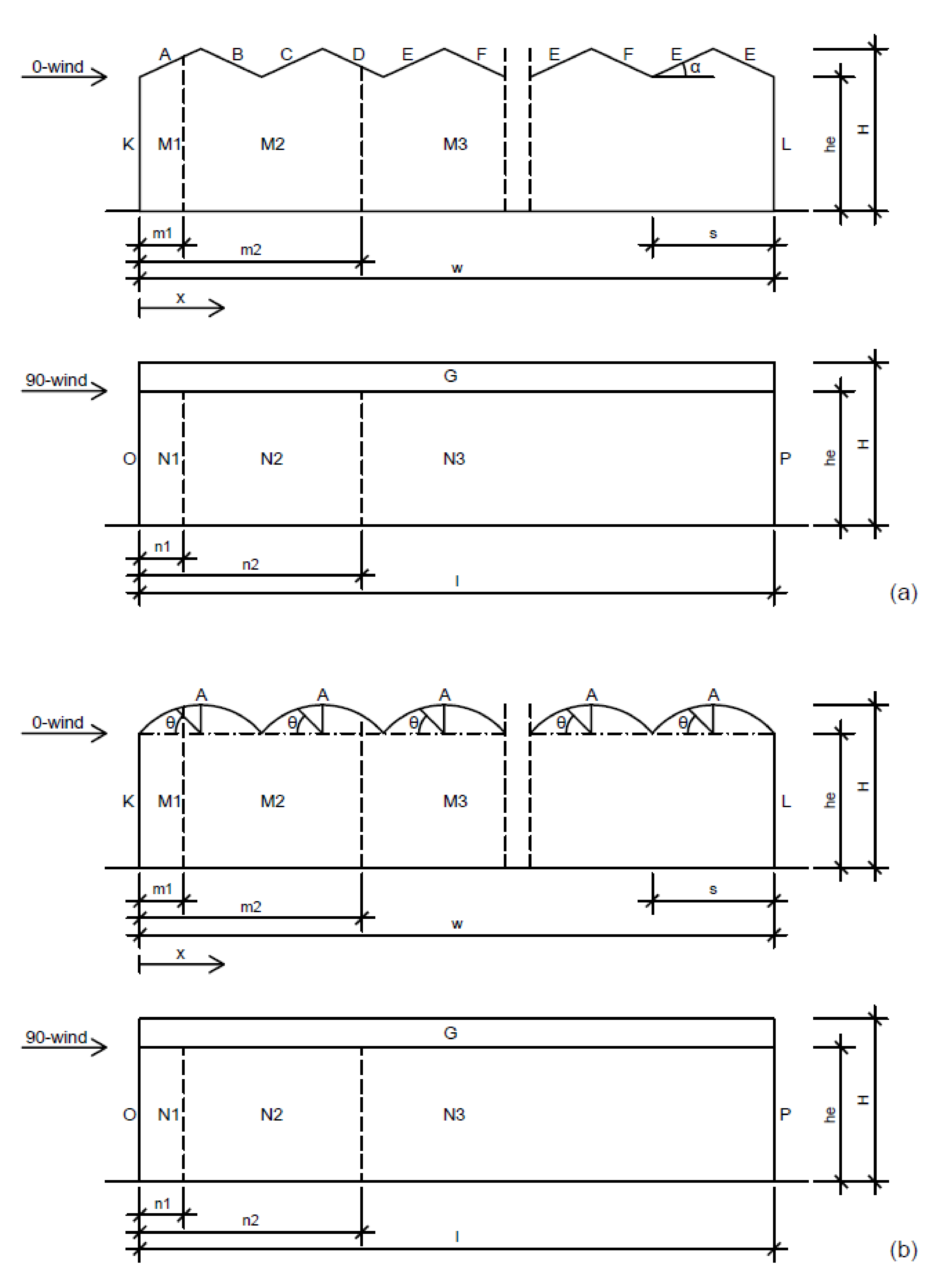
- α = Roof angle of a pitched roof
- θ = Radial angle of an arched roof
- h = Reference height for pressure coefficients, with h = max (he; 0,75 H)
- hg = Gutter height measured from ground level
- he = Eaves height measured from ground level
- H = Ridge height measured from ground level
- s = Width of one single roof span
- w = Total width of the greenhouse with w = nS ∙ s (total width of a multi-span roof)
- l = Overall length of the greenhouse in the direction parallel to the ridge
3. Computational Fluid Dynamics (CFD) Modeling
4. Wind-Tunnel and Full-Scale Tests
4.1. Wind-Tunnel Tests
4.2. Full-Scale Tests
5. Comparison Between EN 13031-1-Provided and Kwon et al. (2016)-Provided Wind Pressure Coefficients for Single-Span Greenhouses
5.1. General
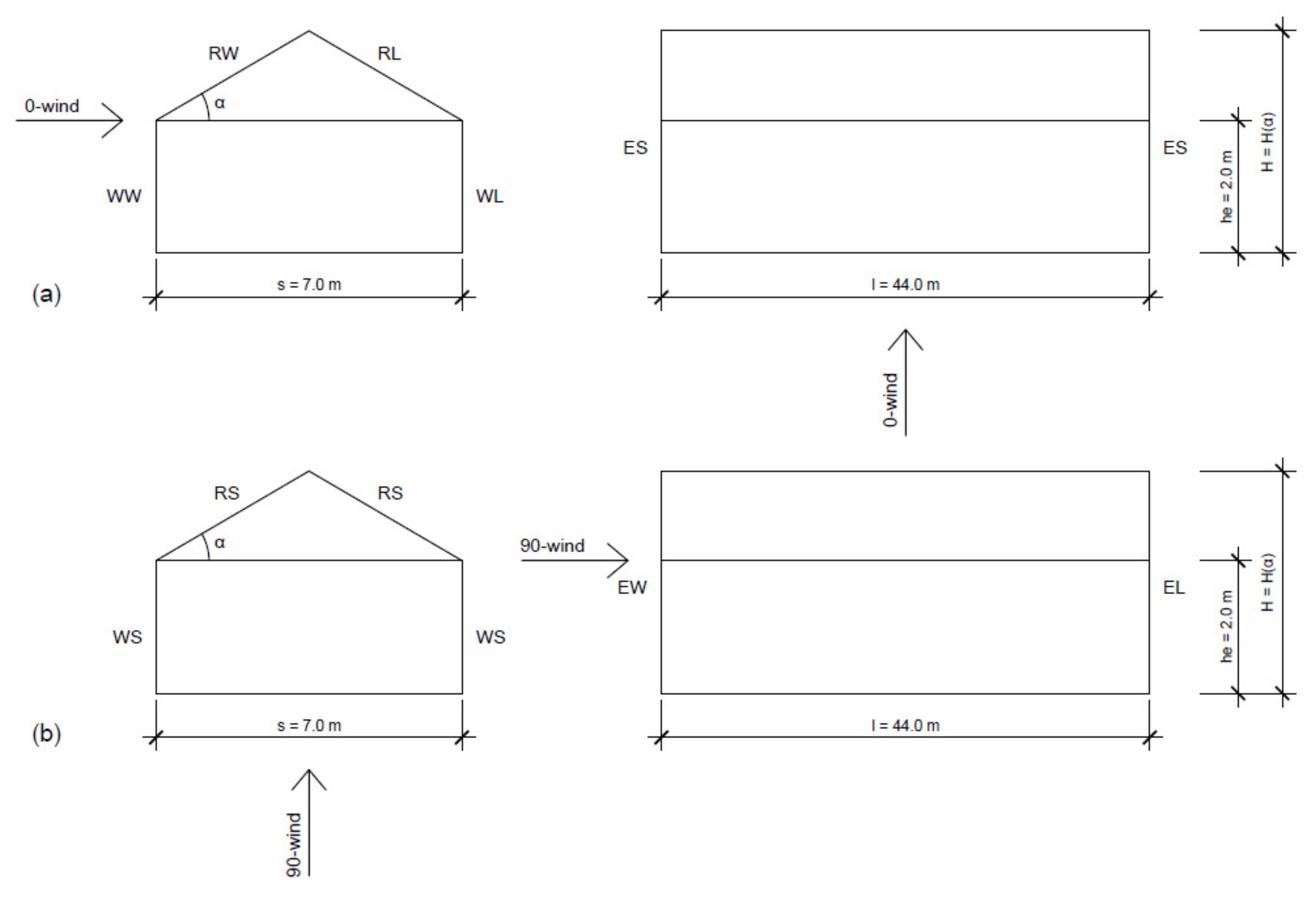
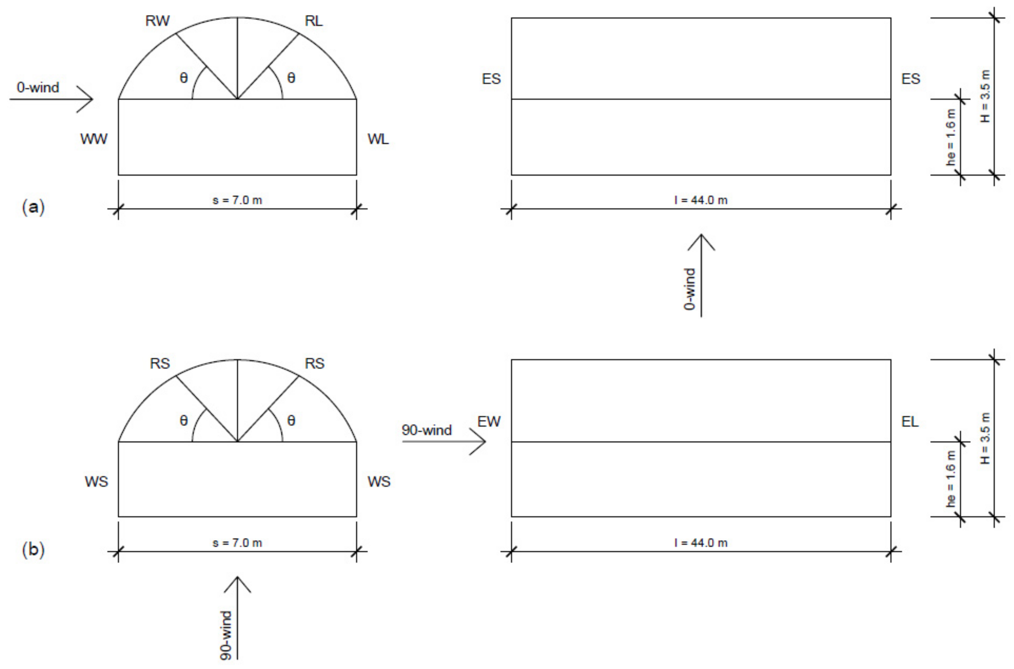
- For the 0°-wind (see Figure 4a and Figure 5a), the wall surface on the windward side is represented by WW (Wall Windward) and that on the leeward side by WL (Wall Leeward). The roof surface on the windward side is represented by RW (Roof Windward) and that on the leeward side by RL (Roof Leeward). Both walls located at the end parts of the greenhouse are represented by ES (End Side).
5.2. Pitched Roof Greenhouses
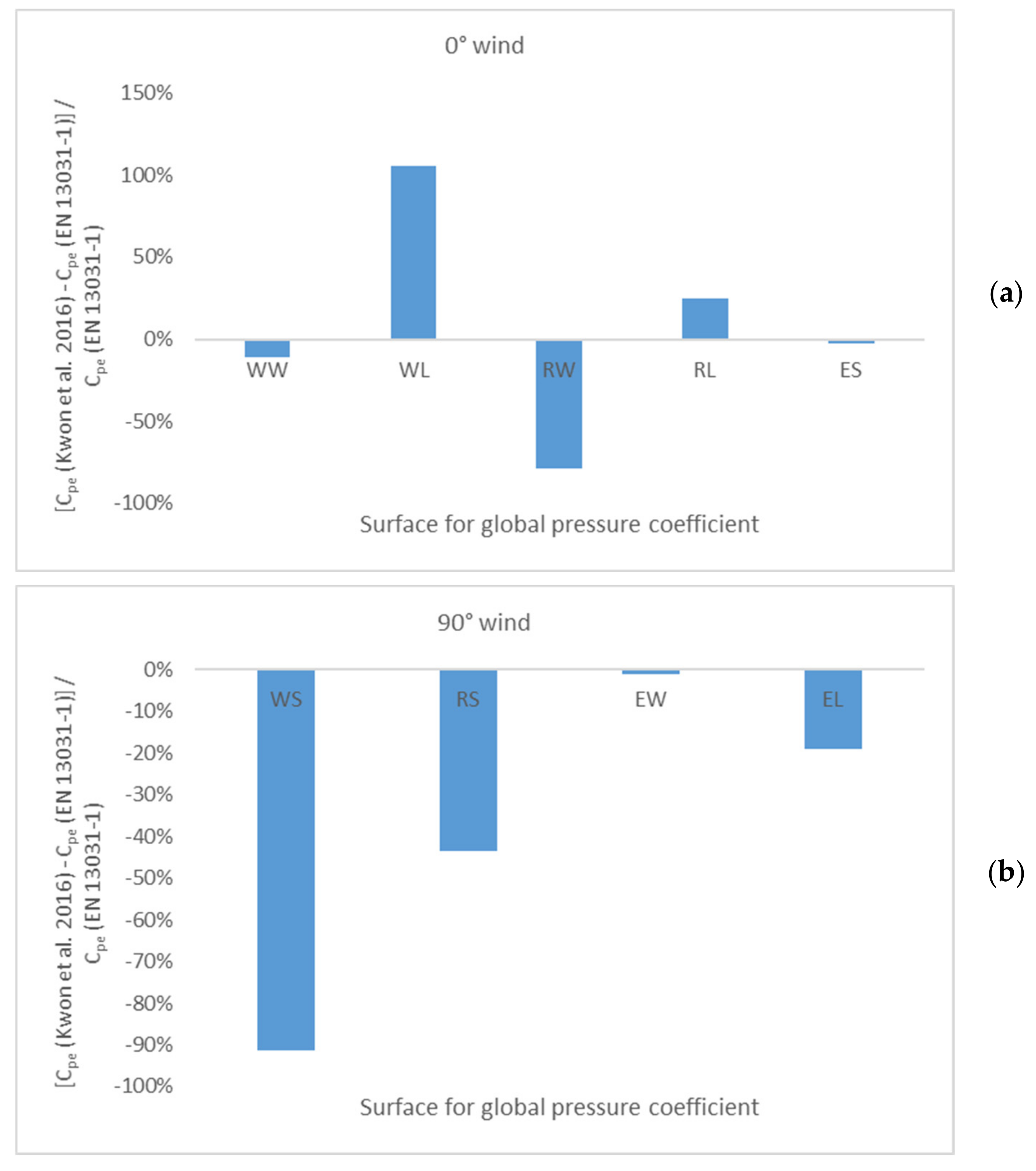
- For the 0°-wind, the Kwon et al. pressure coefficients for the wall and roof surfaces on the leeward side (WL and RL) are higher than those suggested in EN 13031-1. On the other hand, EN 13031-1 coefficients for the roof surfaces on the windward side (RW) are higher than those in Kwon et al. Finally, the pressure coefficients for the wall surfaces on the windward side (WW) and at the end parts (ES) are practically the same.
- For the 90°-wind, EN 13031-1 systematically leads to higher pressure coefficients than Kwon et al., particularly concerning the surfaces of the side walls (WS).
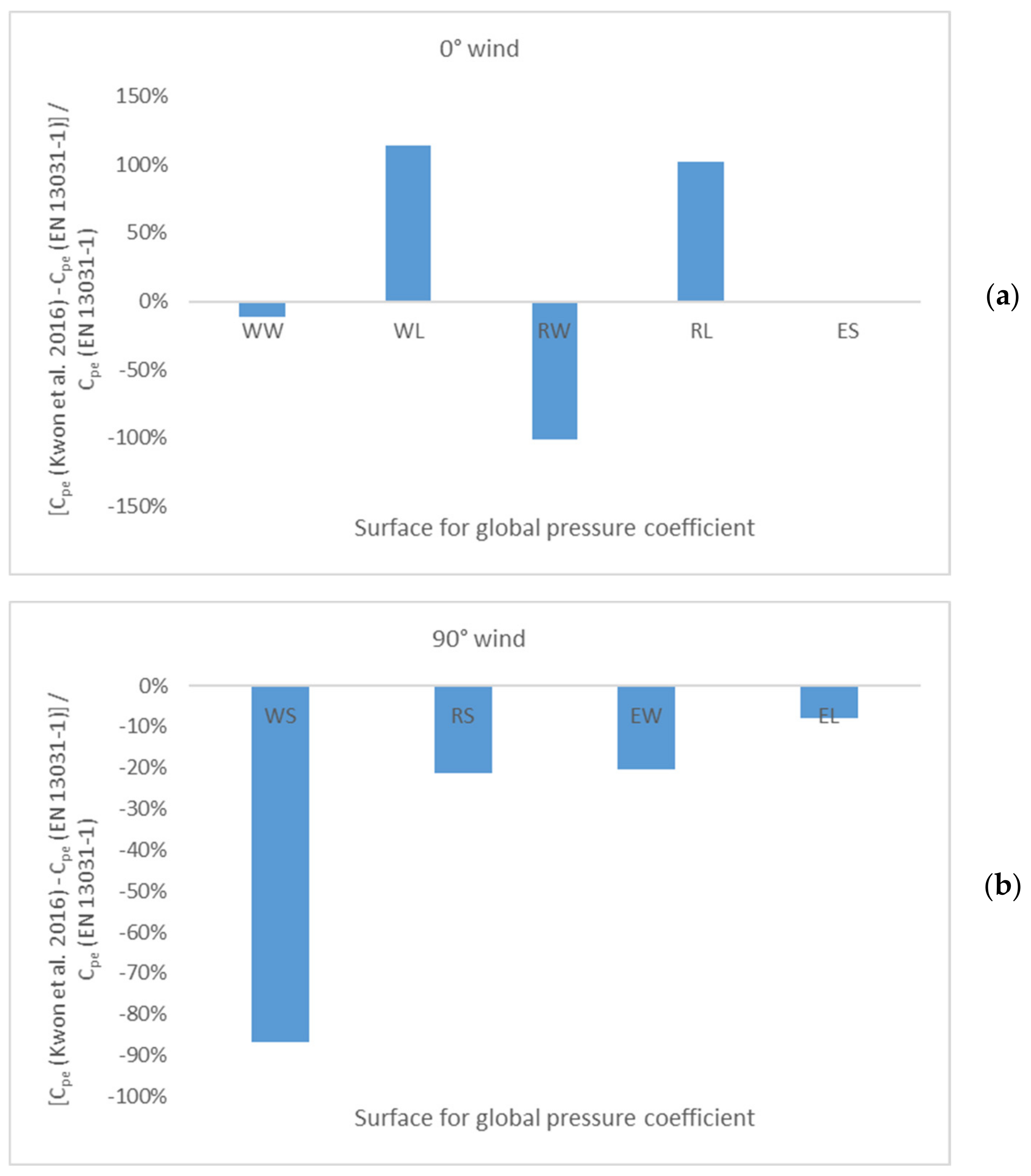
5.3. Arched Roof Greenhouses
6. Comparison Between EN 13031-1-Provided and Measured Wind Pressures for Multi-Span Greenhouses
- -
- The nine greenhouses had a ridge height of 8.1 m, an eaves height of 7.0 m, and a roof height of 1.1 m. The roof span was 5.0 m and the roof angle of 24.3°. The width was varied from 50 (10 spans) to 450 m (90 spans).
- -
- The 30-span greenhouse had a ridge height of 7.5 m, an eaves height of 6.4 m, and a roof height of 1.1 m. The span was 5.0 m and the roof pitch angle of 23.3°.
7. Conclusions
- For a 0°-wind direction, the measured pressure coefficients for the wall and roof surfaces on the leeward side (WL and RL) are higher than those suggested in EN 13031-1. Contrary, EN 13031-1 coefficients for the roof surfaces on the windward side (RW) are higher than the measured ones. The pressure coefficients for the wall surfaces on the windward side (WW) and at the end parts (ES) are practically the same.
- For a 90°-wind direction, EN 13031-1 systematically leads to higher pressure coefficients than Kwon et al., particularly concerning the surfaces of the side walls (WS).
Funding
Conflicts of Interest
References
- Research and Markets. Commercial Greenhouse Market by Equipment (Heating Systems, Cooling Systems, and Others), Type (Glass Greenhouse, Plastic Greenhouse and Others), Crop Type, & by Region—Global Trends & Forecasts to 2020. Available online: http://www.researchandmarkets.com/research/whwdg8/commercial (accessed on 25 February 2020).
- Westland (Municipality), Netherlands. Wikipedia, the Free Encyclopedia. Available online: https://en.wikipedia.org/wiki/Westland_(municipality),_Netherlands (accessed on 25 February 2020).
- CEN. EN 13031-1: Greenhouses: Design and Construction—Part 1: Commercial Production Greenhouses; European Committee for Standardization: Brussels, Belgium, 2019. [Google Scholar]
- Cook, N.J. The Designer’s Guide to Wind Loading of Building Structures—Part 1: Background, Damage Survey, Wind Data and Structural Classification; Butterworths: London, UK, 1985; p. 371. [Google Scholar]
- Cook, N.J. The Designer’s Guide to Wind Loading of Building Structures—Part 2: Static Structures; Butterworths: London, UK, 1990; p. 586. [Google Scholar]
- CEN. Eurocode EN 1991-1-4: Actions on Structures—Part 1-4: General Actions—Wind Actions; European Committee for Standardization: Brussels, Belgium, 2010. [Google Scholar]
- Kwon, K.; Kim, D.; Kim, R.; Ha, T.; Lee, I. Evaluation of wind pressure coefficients of single-span greenhouses built on reclaimed coastal land using a large-sized wind tunnel. Biosyst. Eng. 2016, 141, 58–81. [Google Scholar] [CrossRef]
- Gavanski, E.; Cook, N.J. Evaluation of XIMIS for Assessing Extreme Pressure Coefficients. Front. Built Environ. 2019, 5, 1–15. [Google Scholar] [CrossRef]
- Fouad, N.S.; Mahmoud, G.H.; Nasr, N.E. Comparative study of international codes wind loads and CFD results for low rise buildings. Alex. Eng. J. 2008, 57, 3623–3639. [Google Scholar] [CrossRef]
- Gomes, M.G.; Rodrigues, A.M.; Mendes, P. Experimental and numerical study of wind pressures on irregular-plan shapes. J. Wind Eng. Ind. Aerodyn. 2005, 93, 741–756. [Google Scholar] [CrossRef]
- Hwang, H.S.; Lee, I.B. Wind pressure coefficient determination for greenhouses built in a reclaimed land using CFD technique. In Proceedings of the International Conference of Agricultural Engineering (AgEng 2014), Lausanne, Switzerland, 6–10 July 2014; pp. 1–8. [Google Scholar]
- Kuroyanagi, T. Investigating air leakage and wind pressure coefficients of single-span plastic greenhouses using computational fluid dynamics. Biosyst. Eng. 2017, 163, 15–27. [Google Scholar] [CrossRef]
- Kim, R.; Lee, I.; Kwon, K. Evaluation of wind pressure acting on multi-span greenhouses using CFD technique, Part 1: Development of the CFD model. Biosyst. Eng. 2017, 164, 235–256. [Google Scholar] [CrossRef]
- Kim, R.; Hong, S.; Lee, I.; Kwon, K. Evaluation of wind pressure acting on multi-span greenhouses using CFD technique, Part 2: Application of the CFD model. Biosyst. Eng. 2017, 164, 257–280. [Google Scholar] [CrossRef]
- Shklyar, A.; Arbel, A. Numerical model of the three-dimensional isothermal flow patterns and mass fluxes in a pitched-roof greenhouse. J. Wind Eng. Ind. Aerodyn. 2004, 92, 1039–1059. [Google Scholar] [CrossRef]
- Moriyama, H.; Sase, S.; Uematsu, Y.; Yamaguchi, T. Wind pressure coefficient of a pipe-framed greenhouse and influence if the side gable openings using a wind tunnel. J. SASJ 2008, 38, 237–248. [Google Scholar]
- Yang, Z.Q.; Li, Y.X.; Xue, X.P.; Huang, C.R. Wind loads on single-span plastic greenhouses and solar greenhouses. HortTechnology 2013, 23, 622–628. [Google Scholar] [CrossRef]
- Bronkhorst, A.J.; Geurts, C.P.; Van Bentum, C.A.; Van der Knaap, L.P.M.; Pertermann, I. Wind Loads for Stability Design of Large Multi-Span Duo-Pitch Greenhouses. Front. Built Environ. 2017, 3, 1–21. [Google Scholar] [CrossRef]
- Mathews, E.H.; Meyer, J.P. Numerical modelling of wind loading on a film clad greenhouse. Build. Environ. 1987, 22, 129–134. [Google Scholar] [CrossRef]
- Hoxey, R.P.; Wells, D.A. Full-scale wind pressure measurements on a twin-span 12.2 × 12.2 m inflated roof greenhouse. J. Wind Eng. Ind. Aerodyn. 1977, 2, 211–221. [Google Scholar] [CrossRef]
- Wells, D.A.; Hoxey, R.P. Measurements of wind loads on full-scale glasshouses. J. Wind Eng. Ind. Aerodyn. 1980, 6, 139–167. [Google Scholar] [CrossRef]
- Hoxey, R.P.; Richardson, G.M. Wind loads on film plastic greenhouses. J. Wind Eng. Ind. Aerodyn. 1983, 11, 225–237. [Google Scholar] [CrossRef]
- Hoxey, R.P.; Richardson, G.M. Measurements of wind loads on full-scale film plastic clad greenhouses. J. Wind Eng. Ind. Aerodyn. 1984, 16, 57–83. [Google Scholar] [CrossRef]
- Richardson, G.M.; Westgate, G.R. Full-scale measurements of the wind loads on film plastic clad greenhouses: A comparison of measured and calculated strains on the supporting hoops of a tunnel greenhouse. J. Agric. Eng. Res. 1986, 33, 101–110. [Google Scholar] [CrossRef]
- Richardson, G.M. Wind loads on a full-scale film-plastic clad greenhouse: With and without shelter from a windbreak. J. Wind Eng. Ind. Aerodyn. 1986, 23, 321–331. [Google Scholar] [CrossRef]
- Hoxey, R.P.; Moran, P. Full Scale Wind Pressure and Load Experiments—Multispan 167 × 111 m Glasshouse (Venlo); Divisional Note, AFRC Institute of Engineering Research: Silsoe, UK, 1991. [Google Scholar]


| Greenhouse class | A151 and B152 | B102 | B52 |
| Reliability class | RC13 | RC04 | RC04 |
| Reference period for actions n in years | 15 | 10 | 5 |
| 0°-wind (roof) | Single-span roofs | Winward (A) | +0.2 or {α = 20°: −1.1 (h/s ≥ 0.575); 0 (h/s ≤ 0.1) α = 26°: −1 (h/s ≥ 0.8); 0 (h/s ≤ 0.35)} |
| Leeward (B) | −0.8 (h/w ≥ 0.6) −0.6 (h/w = 0.4) −0.5 (h/w ≤ 0.3) | ||
| Multi-span roofs (1st span) | Winward (A) | +0.3 or {α = 20°: −1.1 (h/s ≥ 0.575); 0 (h/s ≤ 0.1) α = 26°: −1 (h/s ≥ 0.8); 0 (h/s ≤ 0.35)} | |
| Leeward (B) | −1.0 (h/s ≥ 0.4) −0.5 (h/s ≤ 0.3) | ||
| Multi-span roofs (2nd span) | Winward (C) | −0.7 (h/s ≥ 0.4) −0.5 (h/s ≤ 0.3) | |
| Leeward (D) | −0.5 | ||
| Multi-span roofs (3rd to last span) | Winward (E) | −0.4 | |
| Leeward (F) | −0.4 | ||
| Equivalent friction coef. per span b | cfr,1 = 0.03 * tan(α) | ||
| 0°-wind (side wall) | Winward (K) | +0.8 (h/w ≥ 1) +0.6 (h/w ≤ 0,25) | |
| Leeward (L) | −0.5 (h/w ≥ 1) −0.3 (h/w ≤ 0,25) | ||
| 0°-wind (associated gable wall) | M1 | −1 | |
| M2 | −0.7 | ||
| M3 | −0.5 | ||
| 90°-wind (roof) | G | cpe (x) = −0.2–1.2 * exp (−1.5 * x/H) | |
| 90°-wind (gable wall) | Winward (O) | +0.8 (h/l ≥ 1) +0.7 (h/l ≤ 0.25) | |
| Leeward (P) | −0.5 (h/l ≥ 1) −0.3 (h/l ≤ 0.25) | ||
| 90°-wind (associated side wall) | N1 | −1 | |
| N2 | −0.7 | ||
| N3 | −0.5 | ||
| 0°-wind (roof) | 1st span | A | θ = Gutter to 55° | +0.3 |
| θ = 55° to 115° (single-span) | −1.0 or −1.2 for flat arches with (H-he)/s < 0.2 and plastic film unstrained against uplifting over the ridge | |||
| θ = 55° to 70° (multi-span) | −1.0 | |||
| θ = 70° to 115° (multi-span) | −1.0 or −1.2 for flat arches with (H-he)/s < 0.2 and plastic film unstrained against uplifting over the ridge | |||
| θ = 115° to Gutter | −0.4 | |||
| 0°-wind (roof) | 2nd span | A | θ = Gutter to 80° | −0.2 |
| θ = 80° to 100° | −0.9 | |||
| θ = 100° to Gutter | −0.3 | |||
| 0°-wind (roof) | 3rd and subsequent spans | A | θ = Gutter to 55° | 60% of 2nd span |
| 0°-wind (side wall) | Winward (K) | +0.6 | ||
| Leeward (L) | −0.6 (h/w ≥ 0.6) −0.3 (h/w ≤ 0.4) | |||
| 0°-wind (associated gable wall) | M1 | −1 | ||
| M2 | −0.7 | |||
| M3 | −0.5 | |||
| 90°-wind (roof) | G | Single-span: cpe (x) = −0.2–1.2 * exp (−1.5 * x/H) Multi-span: cpe (x) = −0.2–1.3 * exp (−1.5 * x/H) | ||
| 90°-wind (gable wall) | Winward (O) | +0.7 | ||
| Leeward (P) | −0.3 | |||
| 90°-wind (associated side wall) | N1 | −1 | ||
| N2 | −0.7 | |||
| N3 | −0.5 | |||
| Geometric Variable | Pitched Roof | Arched Roof |
|---|---|---|
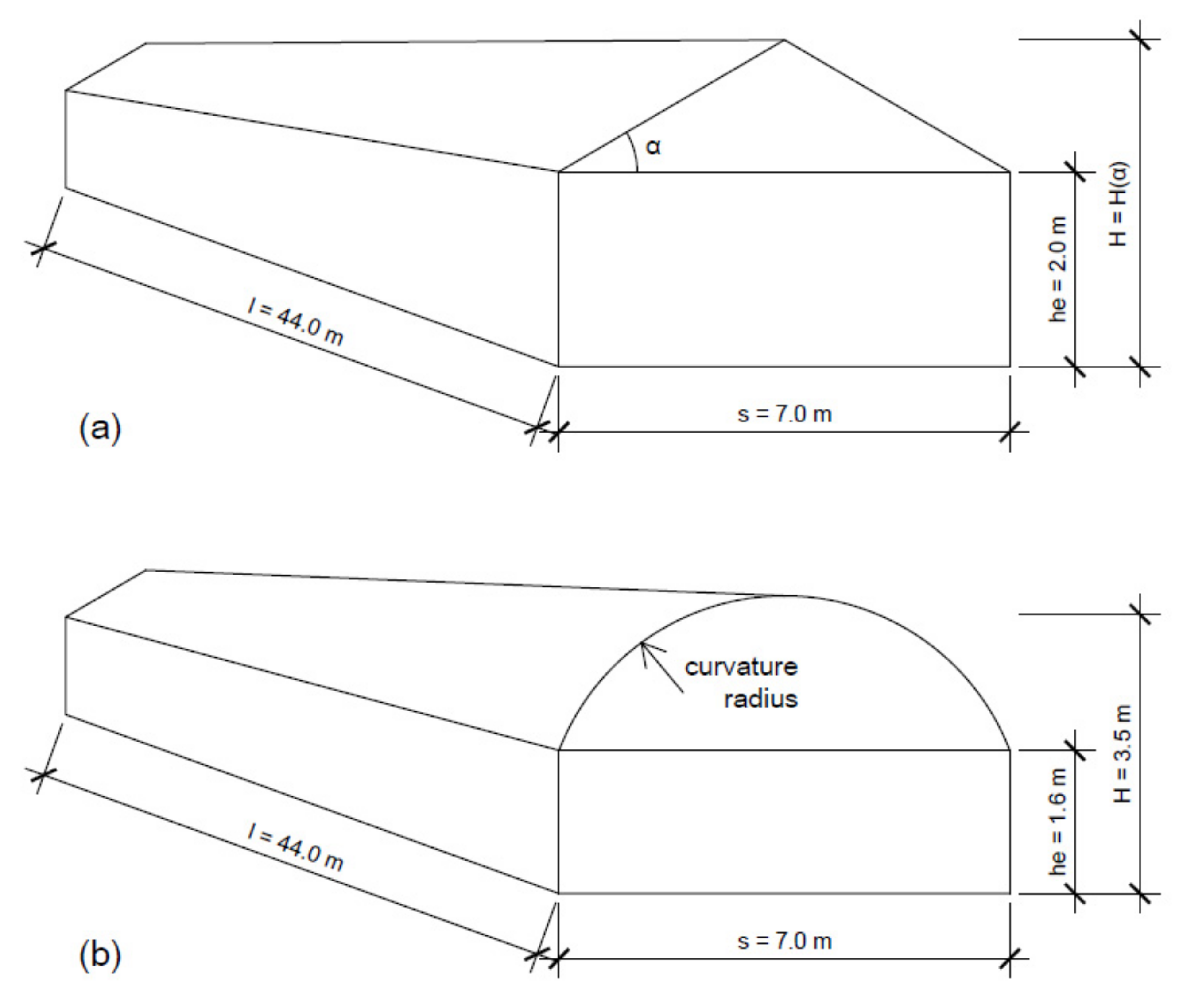
| Roof angle of a pitched roof, α (°) | 22, 24, 26, 28, 30, 32 | - |
| Curvature radius of roof (m) | - | 4, 4.5, 5, 5.5, 6, 6.5 |
| Eaves height measured from ground level, he (m) | 2 | 1.6 |
| Width of one single roof span, s (m) | 7 | 7 |
| Overall length of the greenhouse in the direction parallel to the ridge, l (m) | 44 | 44 |
| Ridge height measured from ground level, H = f (α) (m) | 3.41–4.19 | 3.5 |
| Reference height for pressure coefficients, h = max (he; 0.75 H) (m) | 2.56–3.14 | 2.63 |
| Wind Direction (°) | Surface | Wind Pressure Coefficient | |||||
|---|---|---|---|---|---|---|---|
| Roof Slope a (°) | |||||||
| 22 | 24 | 26 | 28 | 30 | 32 | ||
| 0 | WW | 0.64 | 0.61 | 0.57 | 0.56 | 0.53 | 0.50 |
| WL | −0.67 | −0.68 | −0.71 | −0.72 | −0.71 | −0.72 | |
| RW | −0.31 | −0.21 | −0.18 | −0.10 | −0.04 | 0.03 | |
| RL | −0.76 | −0.74 | −0.79 | −0.76 | −0.75 | −0.73 | |
| ES | −0.98 | −0.94 | −1.00 | −0.98 | −0.97 | −0.96 | |
| 90 | WS | −0.07 | −0.07 | −0.09 | −0.09 | −0.09 | −0.10 |
| RS | −0.10 | −0.10 | −0.12 | −0.12 | −0.12 | −0.12 | |
| EW | 0.66 | 0.62 | 0.57 | 0.56 | 0.57 | 0.58 | |
| EL | −0.26 | −0.23 | −0.26 | −0.25 | −0.24 | −0.22 | |
| Wind Direction (°) | Surface | Wind Pressure Coefficient | |||||
|---|---|---|---|---|---|---|---|
| Roof Slope a (°) | |||||||
| 22 | 24 | 26 | 28 | 30 | 32 | ||
| 0 | WW | 0.63 | 0.63 | 0.64 | 0.64 | 0.65 | 0.65 |
| WL | −0.33 | −0.33 | −0.34 | −0.34 | −0.35 | −0.35 | |
| RW | −0.42 | −0.26 | −0.10 | 0.05 | 0.21 | 0.37 | |
| RL | −0.57 | −0.58 | −0.60 | −0.61 | −0.63 | −0.65 | |
| ES | −1.00 | −1.00 | −1.00 | −1.00 | −1.00 | −1.00 | |
| 90 | WS | −1.00 | −1.00 | −1.00 | −1.00 | −1.00 | −1.00 |
| RS | −0.20 | −0.20 | −0.20 | −0.20 | −0.20 | −0.20 | |
| EW | 0.60 | 0.60 | 0.60 | 0.60 | 0.60 | 0.60 | |
| EL | −0.30 | −0.30 | −0.30 | −0.30 | −0.30 | −0.30 | |
| Wind Direction (°) | Surface | Wind Pressure Coefficient | ||||||
|---|---|---|---|---|---|---|---|---|
| Curvature Radius of Roof (m) | ||||||||
| 4 | 4.5 | 5 | 5.5 | 6 | 6.5 | EN 13031-1 | ||
| 0 | WW | 0.50 | 0.51 | 0.52 | 0.55 | 0.55 | 0.55 | 0.60 |
| WL | −0.50 | −0.50 | −0.64 | −0.74 | −0.71 | −0.75 | −0.30 | |
| RW (0 < θ < 20) | −0.09 | −0.10 | −0.02 | 0.05 | 0.03 | 0.05 | 0.30 | |
| RW (20 < θ < 40) | −1.09 | −0.95 | −0.79 | −0.53 | −0.46 | −0.44 | 0.30 | |
| RW (40 < θ < 65) | −1.73 | −1.47 | −1.11 | −0.77 | −0.79 | −0.68 | −1.00 | |
| RW (65 < θ < 90) | −1.90 | −1.77 | −1.35 | −0.83 | −0.94 | −0.80 | −1.00 | |
| RL (0 < θ < 20) | −1.76 | −1.86 | −1.36 | −0.87 | −0.90 | −0.84 | −0.40 | |
| RL (20 < θ < 40) | −1.20 | −1.04 | −1.00 | −0.82 | −0.83 | −0.81 | −0.40 | |
| RL (40 < θ < 65) | −0.61 | −0.64 | −0.81 | −0.80 | −0.79 | −0.81 | −0.40 | |
| RL (65 < θ < 90) | −0.50 | −0.55 | −0.73 | −0.79 | −0.78 | −0.81 | −1.00 | |
| ES | −0.96 | −0.90 | −0.97 | −1.07 | −1.01 | −1.11 | −1.00 | |
| 90 | WS | −0.17 | −0.14 | −0.13 | −0.11 | −0.13 | −0.12 | −1.00 |
| RS (0 < θ < 20) | −0.17 | −0.16 | −0.16 | −0.15 | −0.15 | −0.15 | −0.20 | |
| RS (20 < θ < 40) | −0.19 | −0.17 | −0.18 | −0.15 | −0.16 | −0.16 | −0.20 | |
| RS (40 < θ < 65) | −0.19 | −0.17 | −0.18 | −0.15 | −0.16 | −0.16 | −0.20 | |
| RS (65 < θ < 90) | −0.20 | −0.19 | −0.19 | −0.16 | −0.17 | −0.17 | −0.20 | |
| RS (90 < θ < 115) | −0.20 | −0.20 | −0.18 | −0.16 | −0.19 | −0.17 | −0.20 | |
| RS (115 < θ < 140) | −0.16 | −0.16 | −0.14 | −0.13 | −0.14 | −0.14 | −0.20 | |
| RS (140 < θ < 160) | −0.15 | −0.15 | −0.13 | −0.12 | −0.13 | −0.13 | −0.20 | |
| RS (160 < θ < 180) | −0.13 | −0.13 | −0.12 | −0.11 | −0.12 | −0.12 | −0.20 | |
| EW | 0.56 | 0.57 | 0.54 | 0.57 | 0.56 | 0.54 | 0.70 | |
| EL | −0.29 | −0.29 | −0.26 | −0.26 | −0.29 | −0.27 | −0.30 | |
| ns | s (m) | l (m) | he (m) | H (m) | α (°) | Reference | Front | Span 1 | Span 2 | Span 3 | Span 4 | Span 5 | Span 6 | Span 7 | Span 8 | Rear | |
|---|---|---|---|---|---|---|---|---|---|---|---|---|---|---|---|---|---|
| 7 | 3.2 | 63.0 | 2.35 | 3.1 | 26 | [21] | 0.52 | −0.76 / –0.94 | –0.7 / –0.45 | –0.29 / –0.4 | - | - | - | - | - | - | |
| EN13031-1 | 0.6 | –0.84 & 0.3 / –1 | –0.7 / –0.5 | –0.4 / –0.5 | –0.4 / –0.5 | –0.4 / –0.5 | –0.4 / –0.5 | –0.4 / –0.5 | - | –0.3 | |||||||
| EN1991-1-4 | 0.7 | –0.36 & 0.43 / –0.83 | –0.57 / –0.5 | –0.34 / –0.5 | –0.34 / –0.5 | –0.34 / –0.5 | –0.34 / –0.5 | –0.34 / –0.5 | - | –0.3 | |||||||
| 6 | 6.6 | 79.6 | 2.4 | 4.0 | 26 | [21] | 0.66 | –0.11 / –1.23 | –1.12 / –0.66 | –0.45 / –0.53 | –0.22 / –0.52 | - | –0.43 / –0.56 | - | - | –0.44 | |
| EN13031-1 | 0.6 | 0 & 0.3 /–0.8 | –0.62 / –0.5 | –0.4 / –0.5 | –0.4 / –0.5 | –0.4 / –0.5 | –0.4 / –0.4 | - | - | –0.3 | |||||||
| EN1991-1-4 | 0.7 | –0.31 & 0.4 / –0.83 | –0.57 / –0.5 | –0.34 / –0.5 | –0.34 / –0.5 | –0.34 / –0.5 | –0.34 / –0.5 | - | - | –0.3 | |||||||
| 8 | 6.4 | 88.0 | 2.8 | 3.9 | 20 | [21] | 0.32 | –0.85 / –1.01 | –0.77 / –0.56 | –0.4 / –0.55 | - | - | - | - | –0.31 / –0.47 | –0.32 | |
| EN13031-1 | 0.6 | –0.82 & 0.3 / –1 | –0.7 / –0.5 | –0.4 / –0.5 | –0.4 / –0.5 | –0.4 / –0.5 | –0.4 / –0.5 | –0.4 / –0.4 | –0.4 / –0.4 | –0.3 | |||||||
| EN1991-1-4 | 0.7 | –0.37 & 0.29 / –0.87 | –0.53 / –0.52 | –0.32 / –0.52 | –0.32 / –0.52 | –0.32 / –0.52 | –0.32 / –0.52 | –0.32 / –0.52 | –0.32 / –0.52 | –0.3 | |||||||
| 52 | 3.2 | 111.0 | 3.0 | 3.75 | 24 | [26] | 0.32 | –0.93 / –1.02 | –0.84 / –0.71 | –0.49 / –0.56 | –0.4 / –0.51 | –0.36 / –0.48 | –0.32 / –0.43 | –0.31 / –0.44 | - | - | |
| EN13031-1 | 0.6 | –1.03 & 0.3 / –1 | –0.7 / –0.5 | –0.4 / –0.5 | –0.4 / –0.5 | –0.4 / –0.5 | –0.4 / –0.5 | –0.4 / –0.5 | –0.4 / –0.5 | –0.3 | |||||||
| EN1991-1-4 | 0.7 | –0.42 & 0.4 / –0.84 | –0.56 / –0.5 | –0.34 / –0.5 | –0.34 / –0.5 | –0.34 / –0.5 | –0.34 / –0.5 | –0.34 / –0.5 | –0.34 / –0.5 | –0.3 | |||||||
| Front | Span 1 | Span 2 | Span 3 | Spans 10-30 | Rear | ||||||
|---|---|---|---|---|---|---|---|---|---|---|---|
| Wind Facing | Lee Facing | Wind Facing | Lee Facing | Wind Facing | Lee Facing | Wind Facing | Lee Facing | ||||
| Pressure coefficients | |||||||||||
| Pressure measurements [18] | cp | 0.50 | −0.43 | −0.70 | −0.60 | −0.30 | −0.05 | −0.18 | 0.00 | −0.14 | −0.15 |
| [18] | cpe,10 | 0.67 | −0.58 0.05 | −0.73 | −0.72 0.06 | −0.36 | −0.18 0.20 | −0.23 | −0.13 0.21 | −0.20 | −0.19 |
| EN13031-1 | cpe,10 | 0.60 | −1.06 0.30 | −1.00 | −0.70 | −0.50 | −0.40 | −0.50 | −0.40 | −0.40 | −0.30 |
| EN1991-1-4 | cpe,10 | 0.70 | −0.46 0.42 | −0.84 | −0.56 | −0.51 | −0.33 | −0.51 | −0.33 | −0.51 | −0.30 |
| Roof span force coefficients | |||||||||||
| Static force measurements [18] | cFx,rs | - | - | - | - | 0.07 | - | ||||
| Pressure measurements [18] | cFx,rs | - | 0.27 | −0.30 | 0.09 | 0.09 | - | ||||
| [18] | cFx,rs,10 | - | 0.78 | 0.42 | 0.30 | 0.29 | - | ||||
| EN13031-1 | cf,rs | - | 1.30 | −0.20 | 0.10 | 0.00 | - | ||||
| EN1991-1-4 | cf,rs | - | 1.26 | −0.05 | 0.17 | 0.17 | - | ||||
© 2020 by the author. Licensee MDPI, Basel, Switzerland. This article is an open access article distributed under the terms and conditions of the Creative Commons Attribution (CC BY) license (http://creativecommons.org/licenses/by/4.0/).
Share and Cite
Maraveas, C. Wind Pressure Coefficients on Greenhouse Structures. Agriculture 2020, 10, 149. https://doi.org/10.3390/agriculture10050149
Maraveas C. Wind Pressure Coefficients on Greenhouse Structures. Agriculture. 2020; 10(5):149. https://doi.org/10.3390/agriculture10050149
Chicago/Turabian StyleMaraveas, Chrysanthos. 2020. "Wind Pressure Coefficients on Greenhouse Structures" Agriculture 10, no. 5: 149. https://doi.org/10.3390/agriculture10050149
APA StyleMaraveas, C. (2020). Wind Pressure Coefficients on Greenhouse Structures. Agriculture, 10(5), 149. https://doi.org/10.3390/agriculture10050149