Article

The Tower Press for Obtaining Olive Oil: Analysis through Computer-Aided Engineering

by
José Ignacio Rojas-Sola
1,*,
Eduardo De la Morena-De la Fuente
2,
Manuel Jesús Hermoso-Orzáez
1 and
David Hernández-Díaz
3
1
Department of Engineering Graphics, Design and Projects, University of Jaén, 23071 Jaén, Spain
2
‘Engineering Graphics and Industrial Archaeology’ Research Group, University of Jaén, 23071 Jaén, Spain
3
Department of Engineering Graphics and Design, Serra Hunter Programme, Polytechnic University of Catalonia, 08222 Terrassa, Spain
*
Author to whom correspondence should be addressed.
Agriculture 2020, 10(11), 554; https://doi.org/10.3390/agriculture10110554
Submission received: 30 October 2020 / Revised: 15 November 2020 / Accepted: 17 November 2020 / Published: 19 November 2020

Abstract

:
This article analyzes a large tower press used to press crushed olives to obtain olive oil. To this end, a study of computer-aided engineering (CAE) was carried out using the parametric software Autodesk Inventor Professional, consisting of a static analysis using the finite-element method (FEM) of the 3D model of the press under real operating conditions. The tower press has been analyzed in two limit positions: in the rest position, supported on two pillars, and the pressing position, supported on the set of filter discs (basket load) called ‘cargo de capachos’ that contained the previously ground olives. In the first position, static analysis revealed that the maximum von Mises stress was 22.7 MPa, located on the axle of the roller, but this is far from the elastic limit. Moreover, the lowest safety coefficient is 11.16, produced in the contact between the tower and the right pillar and well above the optimal range between 2 and 4. On the other hand, it hardly presents equivalent displacements or deformations that would endanger the operation of the set. The greatest displacement would be in the wooden guide (0.123 mm) and a deformation of 0.027% with respect to its length. These values confirm that, in this position, the tower press was clearly oversized. However, the results obtained regarding the second position are not entirely conclusive. Although the values of the displacements and the equivalent deformations are low, with results similar to those obtained in the first position, with a maximum displacement of 0.1315 mm located in the horizontal beam of the support structure and a maximum equivalent deformation of value 0.385%, located in the contact between the screw and the nut, the same does not happen with the von Mises stress. The software did not obtain a convergent result due to the frustoconical geometry of the bolt that joins the screw and nut, adopting a maximum value of 508.3 MPa. For this point, the safety coefficient is 1.49, which reveals a sizing problem with the proposed solution of resizing the screw thread, giving it more robustness. The rest of the elements work with a safety coefficient above 4.33 so they are also clearly oversized, according to current criteria.

1. Introduction

In Mediterranean culture, olive oil is the most widely consumed natural oil in various cuisines for its culinary qualities and for its benefits for human health. For this reason, at present, many researchers are striving to carry out scientific studies on different aspects of olive grove agriculture so that they result in an improvement of the tree and therefore of its fruit [1,2,3,4,5,6].
Furthermore, the olive-growing heritage has aroused great interest as it is one of the most important manifestations in the world of olive oil [7]. In this sense, the different primitive procedures have been studied, as well as the classical systems of grinding and pressing olives [8].
Until the middle of the 20th century, the process of obtaining virgin olive oil was discontinuous: first, the olives were ground, and later the paste obtained after grinding was pressed and placed in filter discs called ‘capachos’; after this pressing, a mixture of olive oil and vegetation water called ‘alpechín’ was obtained, both components being separated by natural decantation (difference in densities).
However, since the middle of the 20th century, olive oil production has been carried out in modern facilities with stainless steel machines, thanks to a continuous process of extraction of olive oil by centrifugation.
The tower presses were direct action presses, that is to say that their operating principle was based on the action of gravity, as they dropped onto a set of filter discs (basket load) stacked one on top of the other called ‘cargo de capachos’ that contained the paste of the ground olive, with the weight of a large stone tower exerting great pressure (since the greater the mass of stone, the greater the pressure exerted on the basket load), and consequently yielding a greater quantity of olive oil in the first pressing, which was that of the highest quality [8].
At first, the stone tower, which was located inside thick solid walls, was mobile and could be raised or lowered thanks to a wooden screw (spindle) [9]. However, this had the disadvantage of great friction, which caused the tower to lean too much so that the pressure on the basket load was not uniform. For this reason, a series of guides and rollers were incorporated so that the ascent and descent movement was as straight as possible and therefore the action of the pressure on the basket load was as uniform as possible.
Other authors describe it as consisting of solid walls approximately 2.5 m high, which served as a limit to a movable stone tower crossed by a large screw, usually made of cast iron, in such a way that it was raised and dropped onto the basket load [10]. This method would undoubtedly be very advantageous, but it required a great deal of time to move large masses at different heights and, therefore, needed to evolve technologically over time.
The study of olive oil mills and presses has been approached from different points of view, such as the architectural [11,12] or the cultural [13]. However, the study of old devices, as well as the analysis and optimization of their operation, which starts with a 3D CAD (computer-aided design) model [14], followed by a static and/or dynamic analysis of the model using CAE (computer-aided engineering), has been performed. Some examples that have been studied, following this methodology, have been an ancient conical stones olive oil mil [15], a double-acting steam engine [16], a mechanical dredger in the port of Kronstadt [17] and the Hay inclined plane in Coalbrookdale (Shropshire, England) [18]. In the aforementioned investigations, it was possible to demonstrate that said historical inventions were clearly oversized according to the results offered by the static analysis carried out.
This research shows the static analysis carried out on a large tower press used until the middle of the 20th century.
As previously stated, there is no worldwide study from the point of view of mechanical engineering of this type of press, which underlines its novelty, originality and scientific interest. For this reason, the ultimate objective of this research is to perform a static analysis of this press using the finite-element method (FEM) [19,20,21] under real operating conditions, to determine if it was well dimensioned and show, where appropriate, how the model could be optimized.
The remainder of the paper is structured as follows: Section 2 presents the materials and methods used in this investigation; Section 3 then includes the main results such as von Mises stresses, displacements, deformations and safety coefficient; and Section 4 shows the main conclusions.

2. Materials and Methods

The initial material for this research has been the tower press located in the Museo de la Cultura del Olivo in the town of Puente del Obispo (Jaén, Spain) (Figure 1). This press was the object of a study from the point of view of engineering graphics within a research project of the National Research, Development and Innovation Plan of the Government of Spain, where the most notable classic mills and presses were analyzed using infographic techniques for different museums of olive oil in Spain, which allowed us to obtain a reliable 3D CAD model.
Regarding the methodology used to obtain a 3D CAD model, Autodesk Inventor Professional [22], computer-aided design parametric software developed by Autodesk, was used to obtain an accurate and reliable digital restitution of the press.
Finally, it has been possible to perform the CAE simulation from the 3D CAD model using FEM to perform a static analysis of the tower press as a whole.

2.1. Operation of the Tower Press

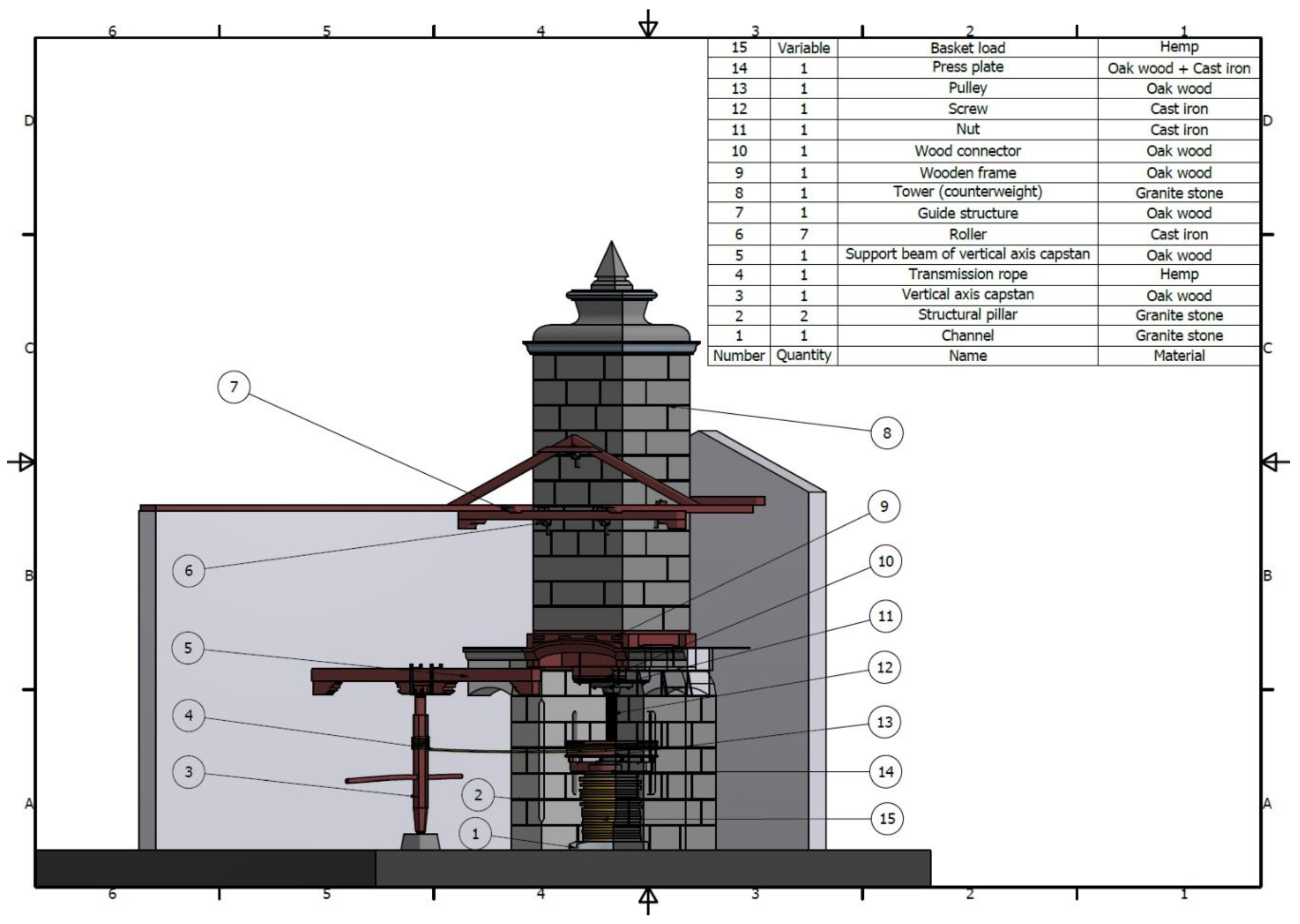
The first step in carrying out a satisfactory analysis is to understand how the tower press worked, and, for this, the assembly plan that includes all its elements will be used (Figure 2).
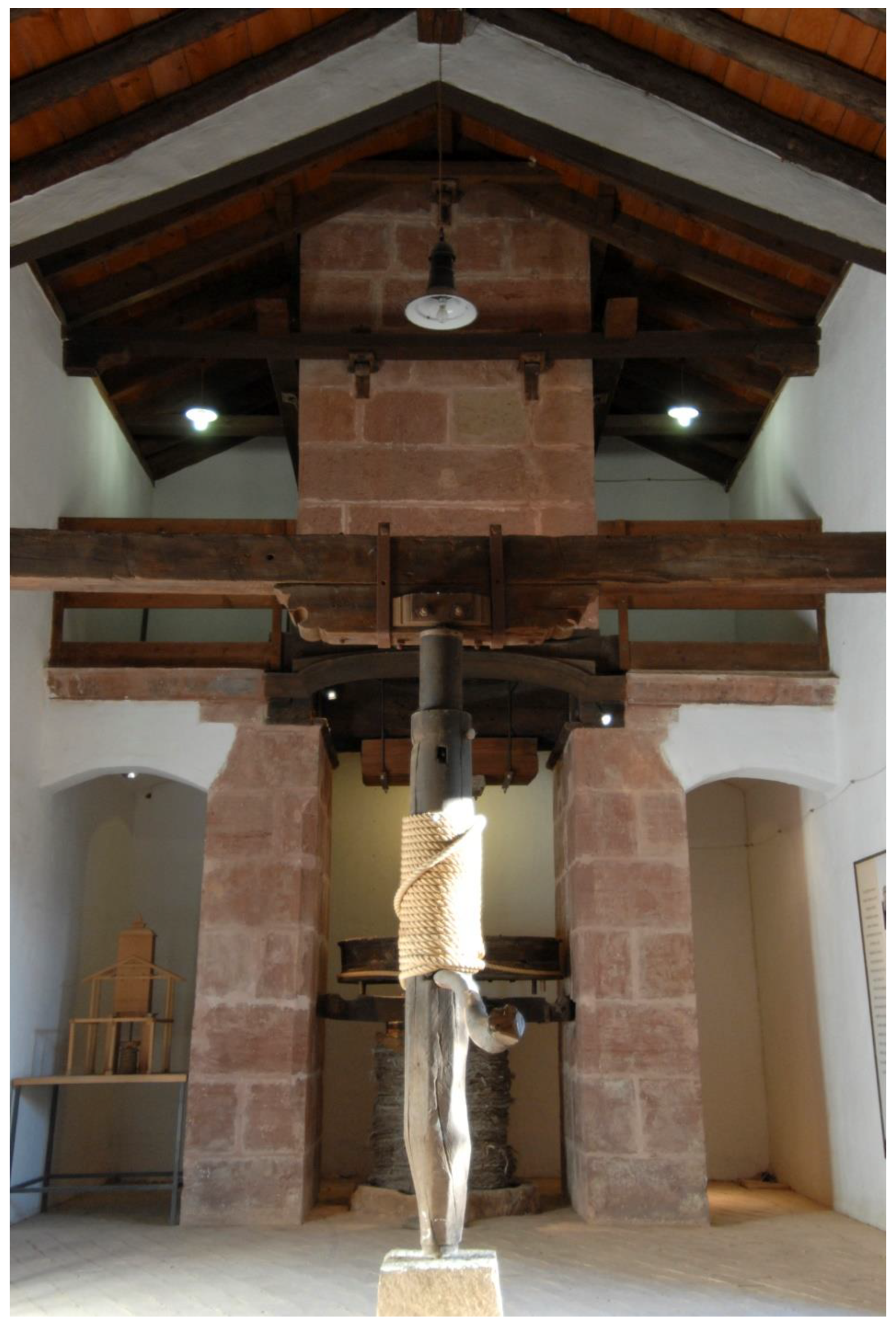
The operating principle of the tower press is common to all direct action gravity pressing systems, that is, it involves dropping a large tower formed by stones onto the basket load (15).
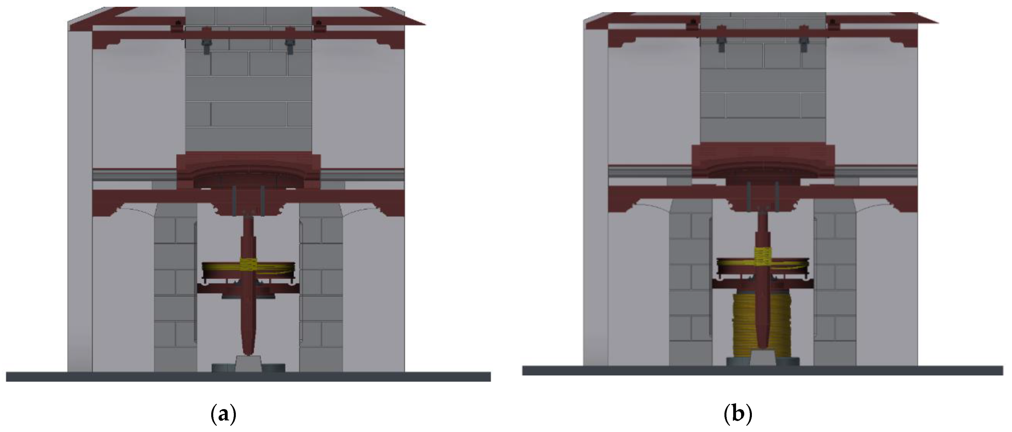
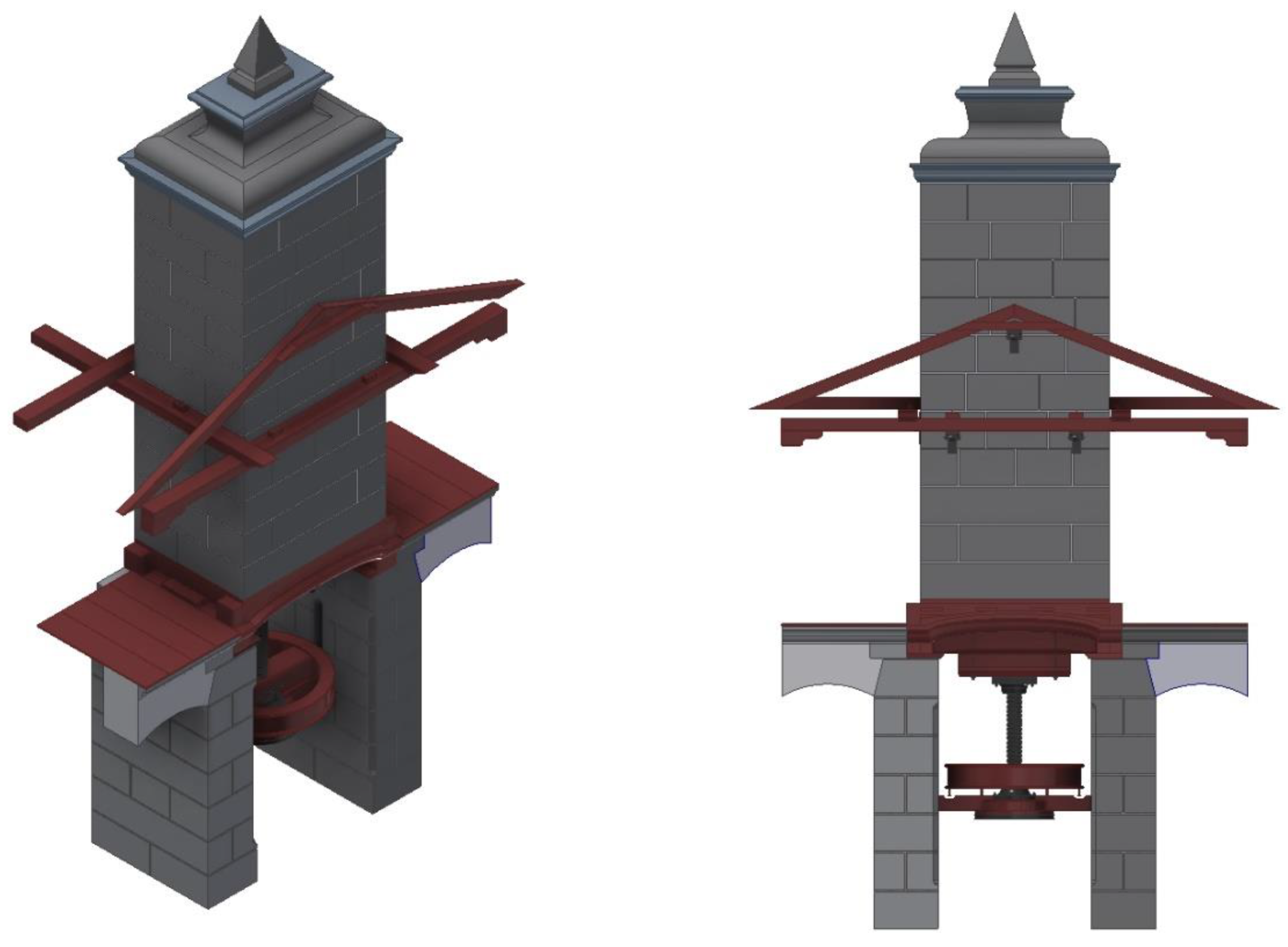
The tower (8) is made of granite and is free to move in the vertical direction thanks to a system of guides and rollers (6) housed in two trusses adjacent to the tower that form a guide structure (7) that guarantees the vertical movement of the tower. The lower part of the tower consists of a wooden frame (9) that has a double function: when there is no pressing, that is, in a resting situation (Figure 3a), this frame rests the weight of the tower on two pillars (2), and when there is pressing (Figure 3b), its weight acts on the basket load (15). These are the two limit positions that are studied in the present research.
To understand how the mechanism works, the starting point is the resting position in which the tower rests on the pillars. In principle, under the element that will directly press the basket load (press plate) called ‘marrano’ (14), there is a free height to form the load. As this basket load is formed and reaches a certain height, the operator operates the vertical axis capstan called ‘palopedro’ (3). This element acts as a manual winch with a vertical axis, supported by a support beam (5) which allows it to rotate. Thus, by rotating the capstan the transmission rope (4) is wound. This makes the pulley (13) rotate, which is attached by means of a large bolt to a cast screw called ‘husillo’ (12). As the screw is turned, it is unscrewed from the nut (11) and begins to descend. At the lower end of the screw is the press plate, which goes down jointly with the screw until at a certain moment it comes into contact with the basket load and the rotation stops.
The ingenuity of the system is that, at that moment, the operators continue turning the capstan, causing the screw to continue moving and the nut to continue unscrewing, but since the press plate can no longer descend, it is the tower that begins to ascend. Specifically, the wooden frame (9) stops leaning on the two pillars and rises a few centimeters, enough so that the weight of the tower is entirely over the basket load, and in a short time, the oily must (olive oil and alpechín mixture) runs through the baskets until it reaches a channel that surrounds the basket load called ‘regaifa’ (1) that collects it. After this time, the tower rests on the pillars, having ‘exhausted’ the basket load and reduced its height, that is, having pressed it completely. Finally, if the pressing has been satisfactory, the operators manually turn the pulley so that the press plate rises and the pressed baskets can be removed.
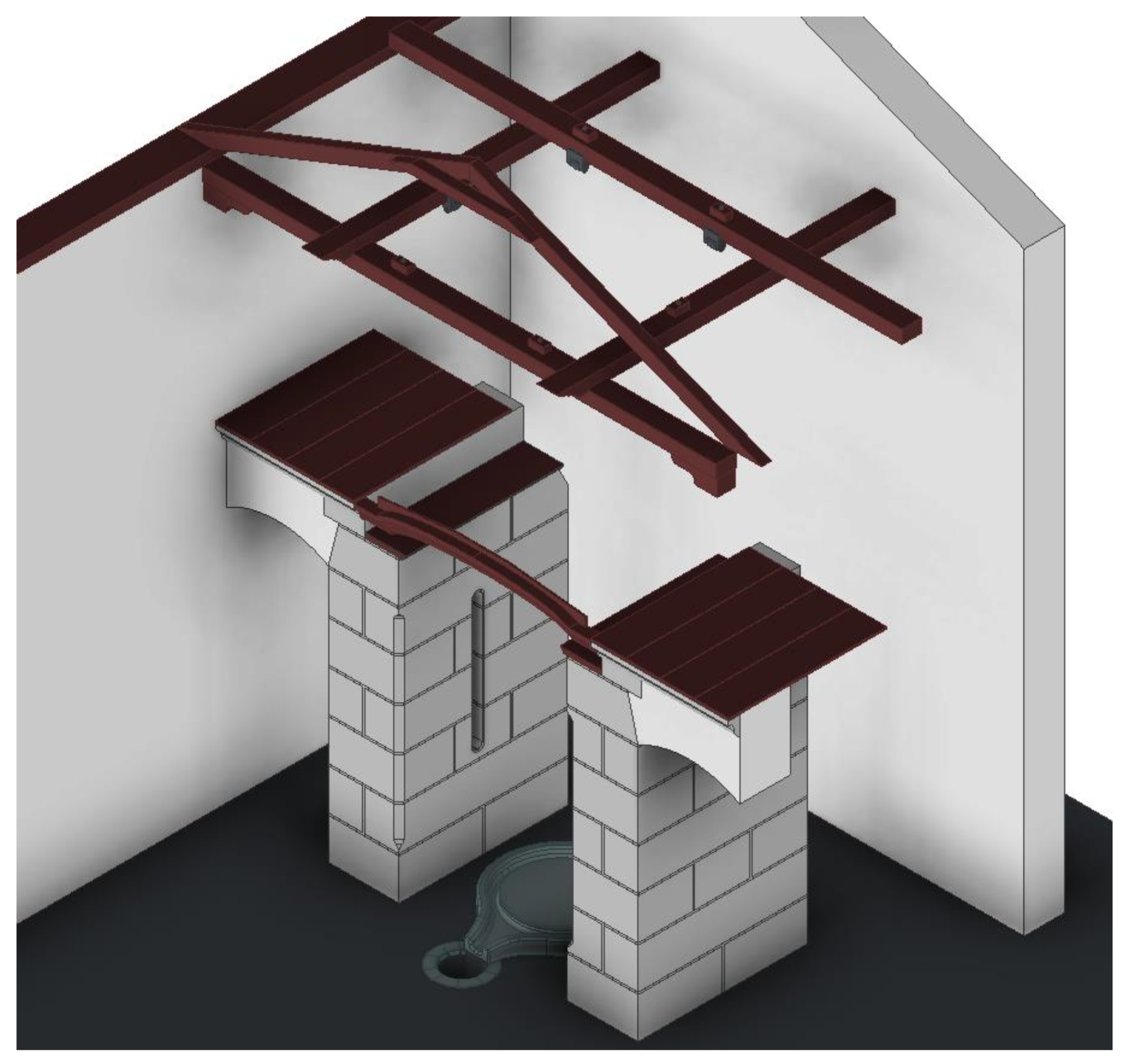
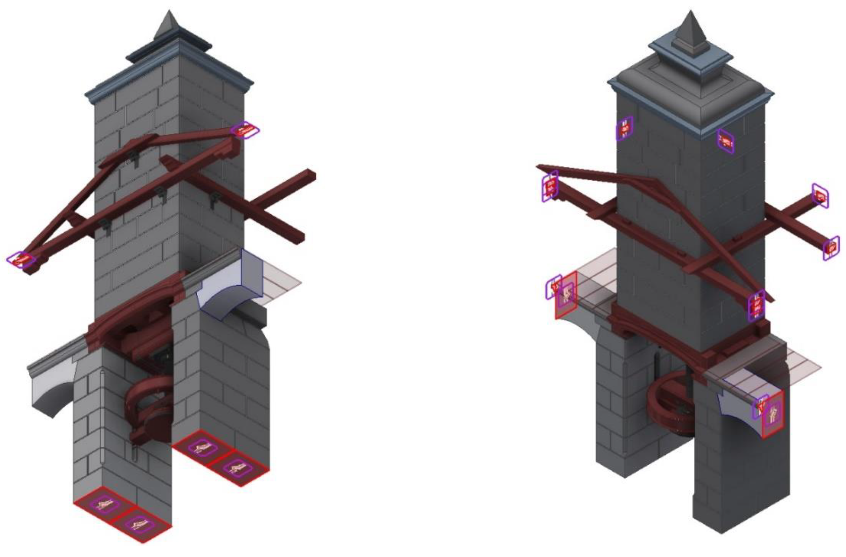
Moreover, the elements of the tower press can be organized from the point of view of their functionality. A first set of elements would be those destined to serve as a support to the tower, such as the structural elements that are fixed, facilitating its vertical movement (
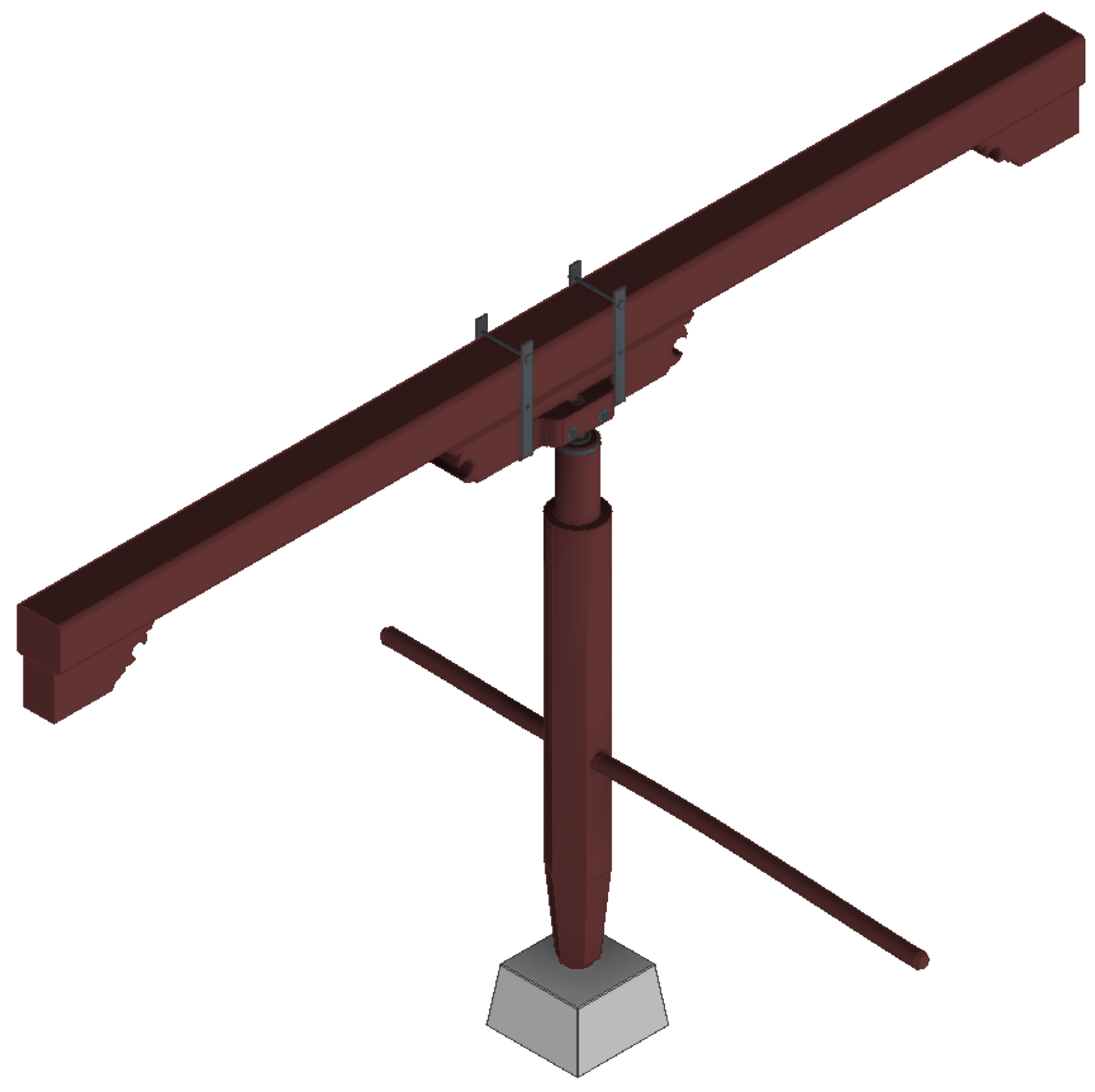
Figure 4). A second set would be the elements of the vertical axis capstan, whose purpose is to operate as a vertical axis winch that facilitates the movement of the press plate and, consequently, of the tower itself (
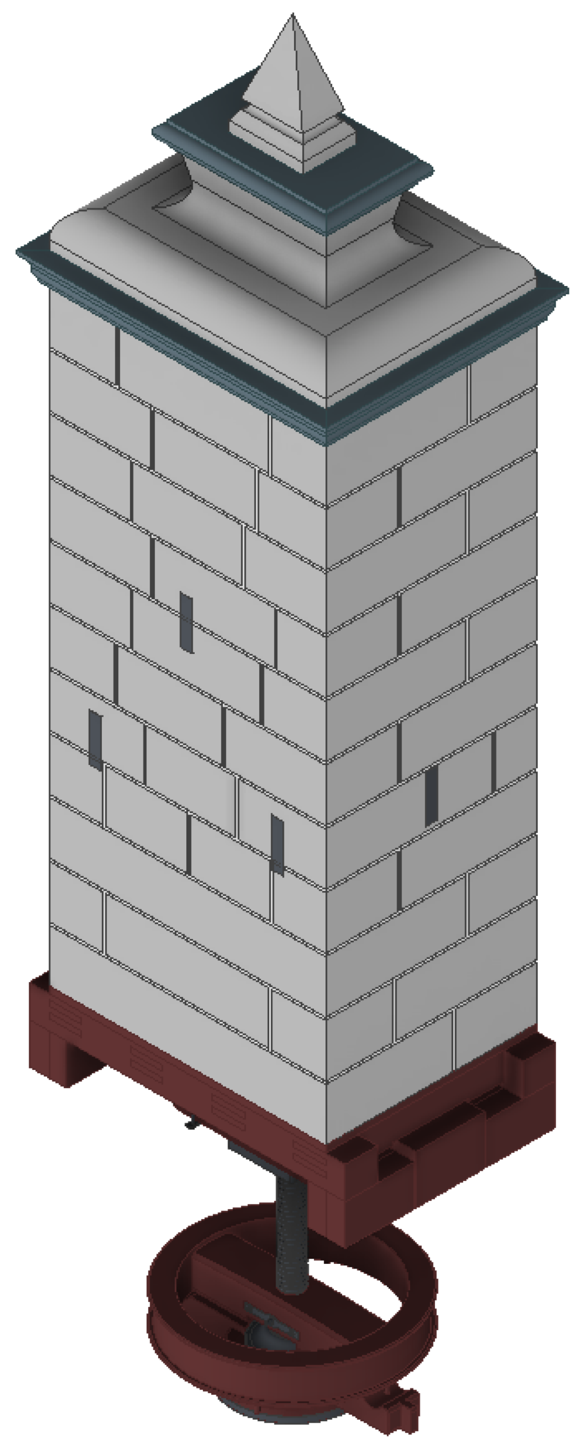
Figure 5). The final set of elements would make up the mobile part of the press and control the process of pressing the basket load that contains the ground olive paste (Figure 6).

2.2. Computer-Aided Engineering (CAE)

From the 3D CAD model, a static analysis has been carried out using the finite-element method (FEM) thanks to Autodesk Inventor Professional software.

2.2.1. Pre-Processing

This is the first step to being able to carry out an effective static analysis of the model, and it consists of simplifying and establishing the positions in which this analysis will be carried out. This is so because there are elements of the model that are not structurally involved in the analysis or also because their presence can be replaced by a movement restriction or a load. However, the simplification process must always respect the results of the analysis, that is, if the model is not simplified, the result should be the same.
From the computational point of view, the greater the number of elements, the greater the geometric mesh and the mathematical model on which to apply FEM, and this mainly translates into a greater demand on the computer processor and, therefore, into a longer calculation time. Therefore, obtaining a simplified model that yields the same results as a non-simplified model enables analysis with lower computational requirements. On the other hand, it is also necessary to determine in which limit positions the model works, as the elements that make up the tower press assembly are subject to different stresses in each position.
Following the order explained previously, the element to be studied has been simplified by eliminating a series of elements of the structural part that will be replaced by movement restrictions at some points, thus generating what are called supports.
The base, the building enclosure and the channel that collects the oily must are not part of the body of the model and are easily replaceable, as will be seen in the boundary conditions section. On the other hand, the entire vertical axis capstan system has no influence on the main structure, since it is responsible for raising or lowering the screw and allowing different positions in the press, but its elimination does not influence the static analysis of the tower press as a whole. Finally, the moving part of the press is adopted without any simplification. Figure 7 shows the simplified model. On this model, the two limit positions shown in Figure 3a,b will be studied: Position 1, in which the tower is supported by the pillars, and Position 2, in which the tower rests on the basket load.

2.2.2. Assignment of Materials

During the 3D modeling process of the tower press, the software allowed us to assign a material to each element of the assembly, although the stress analysis module of Autodesk Inventor Professional also allows users to assign a material to each element again or to modify the physical properties of the assigned material. This is an important task since if any of the elements does not have a material assigned, the software does not allow stress analysis.
On the other hand, the software requires the behavior of the material to be defined, that is, if it is isotropic and has the same properties in all directions, or if it is orthotropic, in which case its properties depend on the direction in which they are measured. In the latter case, it is proposed to replace the orthotropic material with an isotropic one elaborated from an average behavior obtained from its three main directions.
Two isotropic and one orthotropic material have been involved in the present research. The isotropic materials have been cast iron (with which all metal parts were made) and polished granite (for stone materials). The characteristics of these have been obtained from the Autodesk Inventor Professional material library with their defined properties. Thus, the physical properties of cast iron are: Young’s modulus 120,500 MPa, Poisson’s ratio 0.30, density 7150 kg/m3, and an elastic limit of 758 MPa. For its part, polished granite has a Young’s modulus of 55,000 MPa, a Poisson’s ratio of 0.25, a density of 2700 kg/m3, and an elastic limit of 39 MPa.
For elements made of oak wood, considering it as an orthotropic material, the direction of the grain has been defined as the most resistant to the direction of the longest element. Thus, oak wood has been assigned with three different values of Poisson’s ratio and Young’s modulus depending on the direction, but with a constant density value of 760 kg/m3 and an elastic limit of 41 MPa in the direction parallel to the grain.

2.2.3. Boundary Conditions

The third step prior to static analysis is to establish the boundary conditions. As previously stated, the two limit positions to be studied are closely related to the defined supports of the model.
By simplifying the model, some elements of the structure have disappeared and, therefore, it is necessary to correctly define the supports so that the study of the simplified model does not yield different results from the real one.
The supports that are defined are the classic supports used in the calculation of structures: fixed, articulated and mobile supports. However, Autodesk Inventor Professional does not define supports directly, but allows for the restriction of degrees of freedom of movement to specific surfaces, that is, the supports must be defined based on restrictions to the affected surfaces.
Figure 8 shows the surfaces that have a total restriction of movements, which would correspond to a fixed support. These are specifically the pillars of the press in their insertion in the base, the support of the arches and the beams on the walls of the building where the tower press is housed. Furthermore, these boundary conditions are common to the two limit positions to be analyzed, whether the tower is supported by the pillars (Position 1) or the basket load (Position 2).
Figure 9 shows a movement restriction that will only be produced in the case in which the tower rests on the basket load (Position 2). In this case, the lower surface of the press plate rests on the basket load and its vertical movement is impeded. It is, therefore, a mobile support in which the vertical movement of the surface is prevented. Once this support is defined, the model can dispense with the presence of basket load made of a material such as hemp, which is difficult to simulate and has variable physical properties.
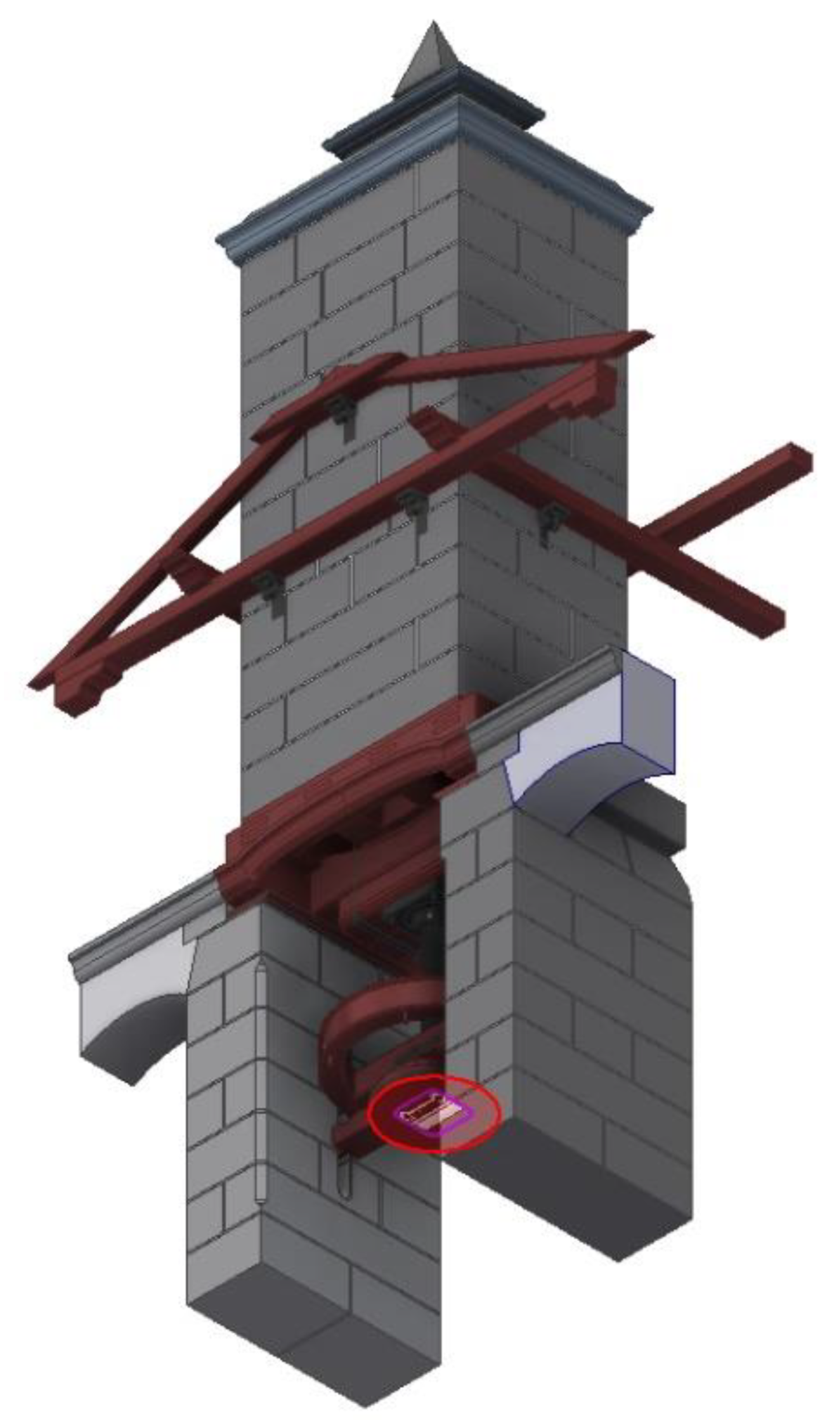
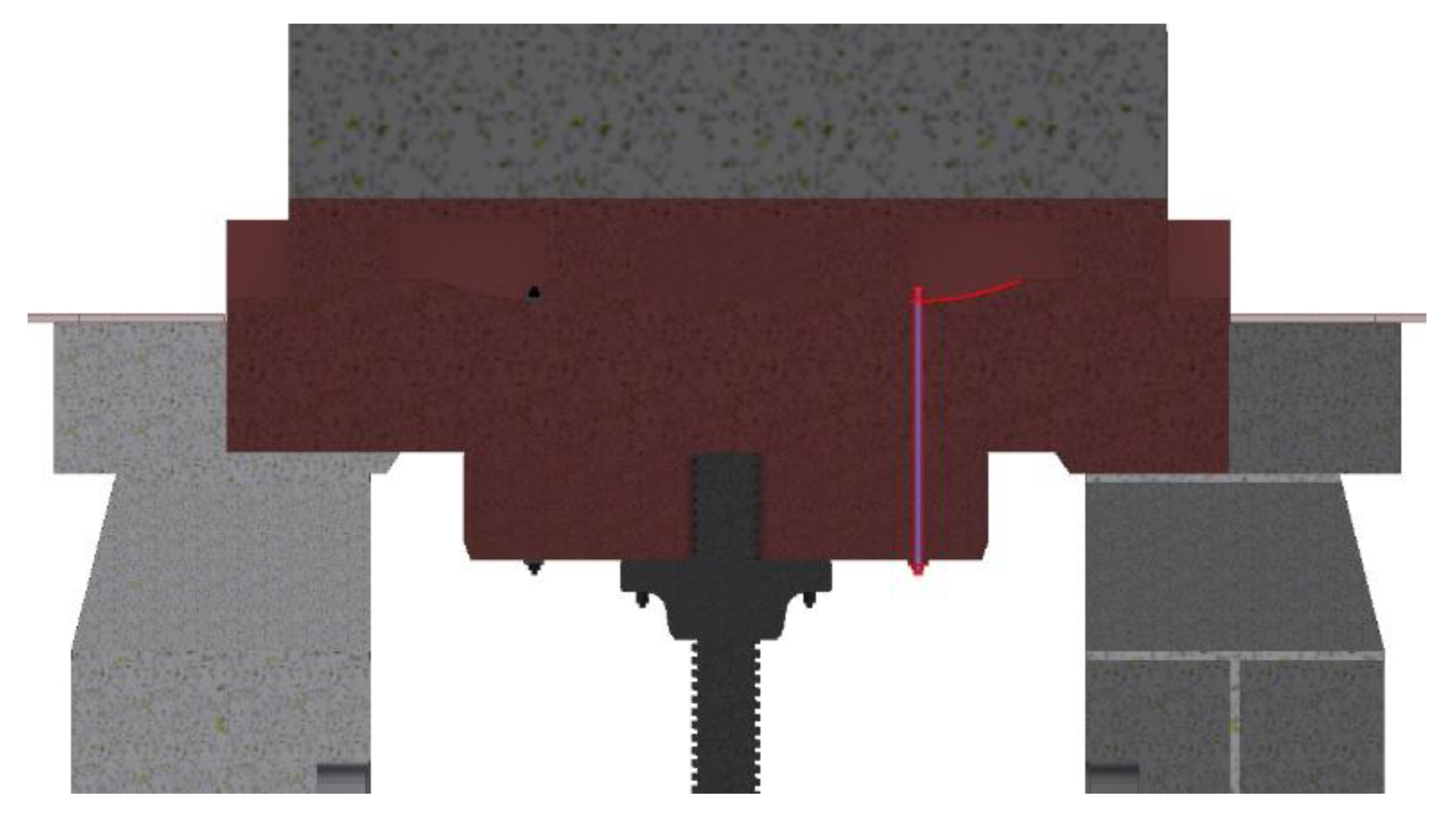
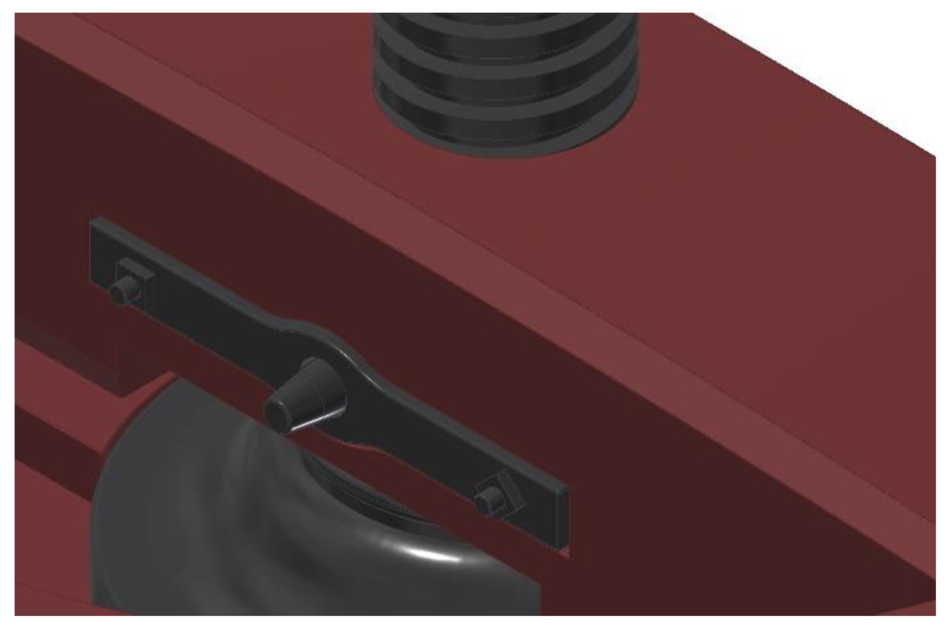
Thus, once the supports have been defined, the software allows the contacts of the different elements that are part of the final assembly to be automatically generated. If the press is well modeled and its geometry is not excessively complicated, the automatic contacts coincide with the actual contacts between elements. In the case of the present research, a difficulty appeared that has been solved by manually defining the contact between elements. These are the metal clamps that join the wooden connector and the wooden frame, made up of two metal plates and the two large screws that join them. The problem is that the contact between the wooden frame and the plate is not flat, and the software is unable to establish it (Figure 10). Therefore, by selecting the surfaces that should be related and accepting the contact, the software corrected this problem. Apart from this difficulty, the software defined the rest of the contacts perfectly.

2.2.4. Forces Applied

The next step is to define the forces that act on the press. At first, it might seem that there are two fundamental forces that intervene on the structure: gravitational action and that from the action of the vertical axis capstan on the pulley, but this is not the case.
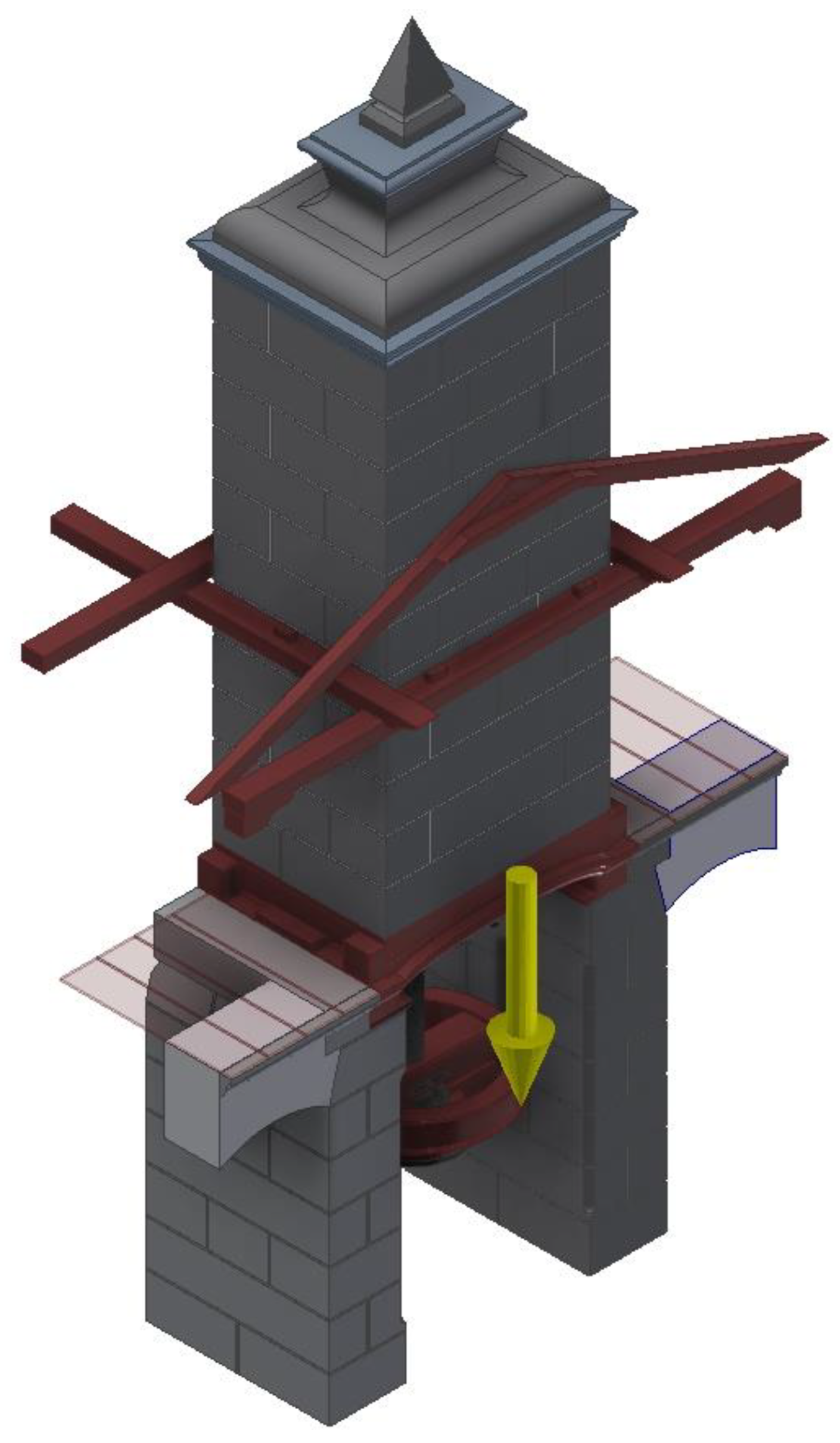
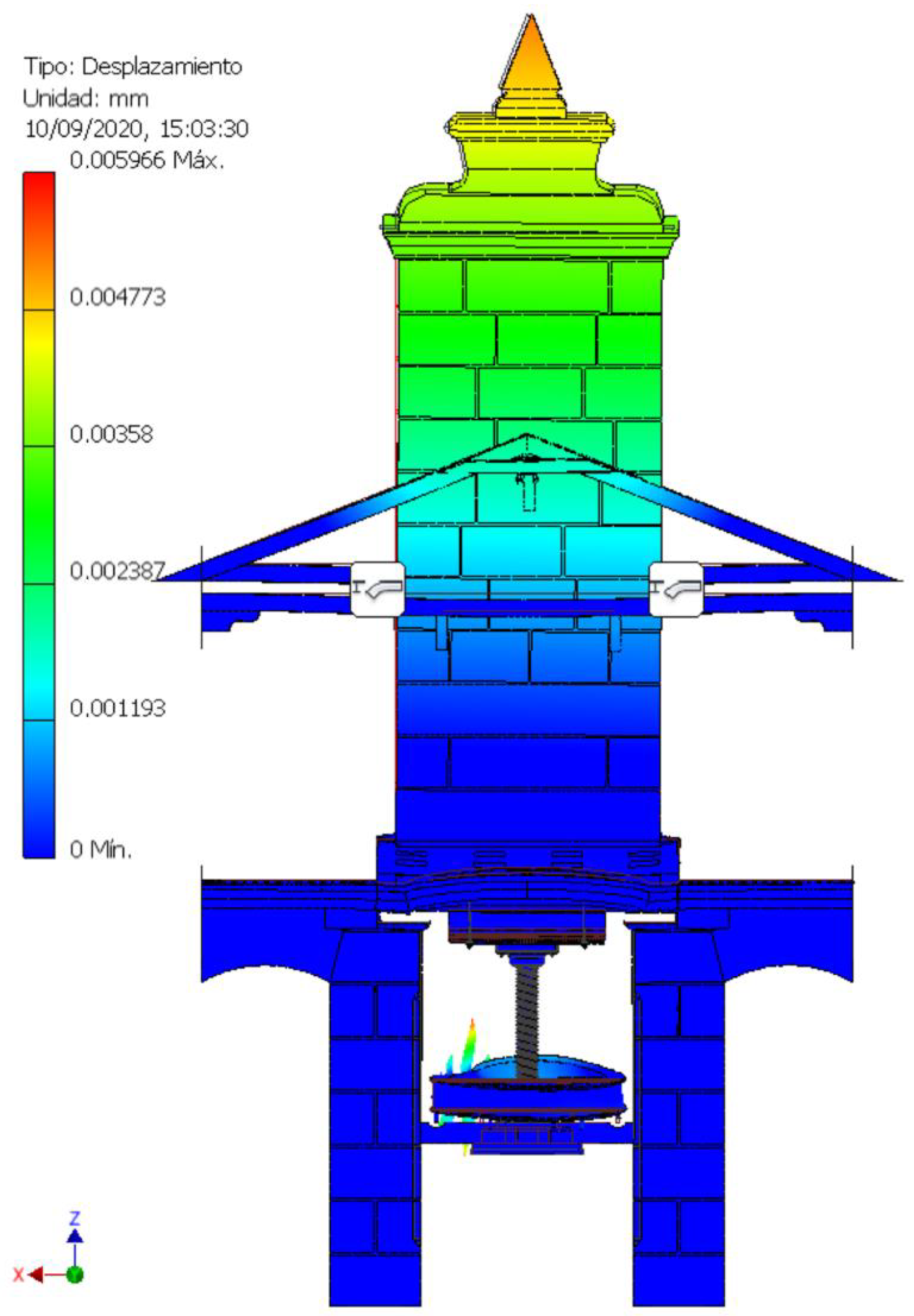
The gravitational action, represented in Figure 11, is the one that affects the set of elements of the model, and as will be explained below, it is the only force that acts in the pressing of the basket load.
To define this force, the acceleration of gravity with a value of 9.81 m/s2 in the negative direction of the z axis has been taken.
The mass of the moving part of the press (tower with a height of 6.93 m), which is what is going to exert pressure on the basket load, is 45,988 kg, which means a force of 451,142 N.
Furthermore, the surface of the press plate that comes into contact with the surface of the baskets is 0.578 m2, so the pressure that will support the charge of baskets is 780,522 Pa, which is more than enough to extract the oily must from the previously-ground olives.
However, the force derived from the action of the vertical axis capstan has no reason to appear in the static analysis of the model, since the function of this element is only to rotate the pulley that is integrally attached to the screw, screwing it or unscrewing it on the nut that joins the connector to the wooden frame.
The pulley rotates freely in Position 1, that is, when there is no lower opposition from the basket load. As the structure is supported by the pillars, the screw can adopt any position without any resistance from the structure. Therefore, in this position, it is unnecessary to define the force.
In Position 2, when the tower is supported by the basket load, the vertical axis capstan must overcome the resistance of the tower to be lifted, which is caused by gravitational action; furthermore, if the capstan is stopped from rotating, the tower does not return to its original position resting on the pillars. Thus, it can be said that Position 2 can be characterized without the intervention of forces on the pulley. This is, therefore, the situation that has been chosen to perform the static analysis, thus avoiding the intervention of more actions than necessary.

2.2.5. Meshing

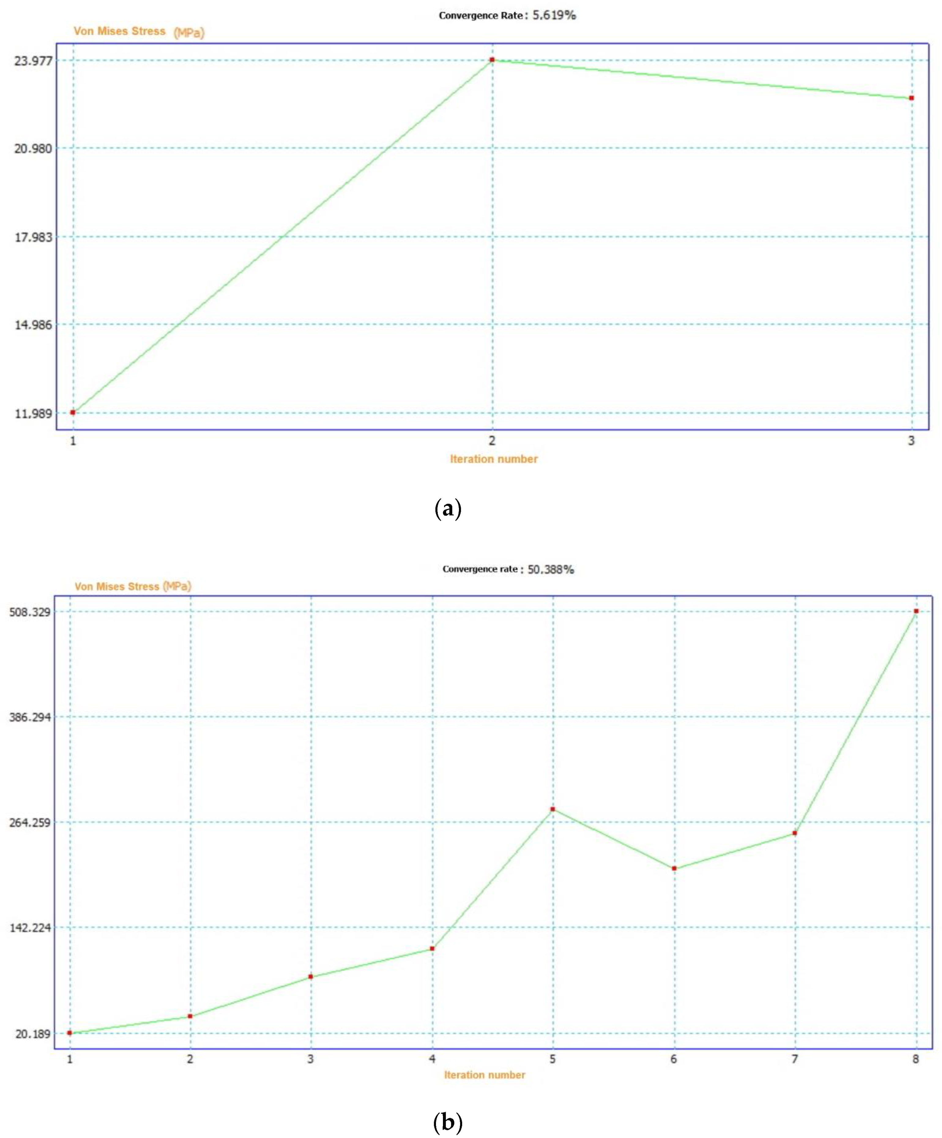
Meshing is the last action to take before running the stress analysis. Meshing consists of the geometric discretization of the model, generating a volumetric network of tetrahedra that simulate its geometry. Each of the vertices of the volume is a node that is related to its neighboring nodes, and the values it presents in relation to those neighboring nodes can be written as a system of linear equations that can be solved by iterative methods. The greater the number of nodes, the greater the computational requirements necessary to solve all the equations.
Generally, the software that performs the FEA uses tetrahedral elements tetra 10 (4 physical points and 10 nodes). More specialized software allows for the use of hexahedral volumes, such as hexa 8, hexa 20 or hexa 27, to perform meshing in dynamic analysis or in static analysis of elements with very complex geometries. The mesh formed by hexahedra, compared to the one formed by the tetrahedral, generates the same volumes with fewer elements, but also with less geometric precision. The choice of hexagonal meshes reduces computational requirements and saves time and maybe from mathematical point of view the result would be better (total number of nodes is reduced and there are fewer differential equations), but the mesh does not conform to the real geometry. In a linear analysis such as the current one, there is no problem in using volumes of tetra 10 because the total number of elements to be analyzed is not excessive and the geometry will be better characterized.
In other types of simulations, for example, in lighting or thermal analysis, the use of bar or shell elements is more frequent. It is evident that this type of element, of a lower order, has much fewer elements (and calculation time) but the problem is, to adapt 2D elements to 3D models, this simplification, which is not always possible, requires time and must be well justified in order to analyze the real model.
It is important to find a balance. The results obtained using higher order meshes, the tetrahedral ones, generally differ little from those obtained by other 3D methods, and the 2D methods are difficult to implement in the present case; therefore, the use of a tetrahedral mesh is the one that has been imposed in this analysis. Furthermore, the mechanism that is being studied, at the time it was built (the study of the calculation of structures had not been extended), is an oversized structure.
On the other hand, the default tetrahedral mesh proposed by Autodesk Inventor Professional has problems when the geometry is complex. To avoid this problem, the software allows for reworking the mesh manually (mesh refinement), determining the maximum distance between nodes in some regions or in regions where stresses are concentrated, since if the mesh fits the geometry better the results are more reliable.
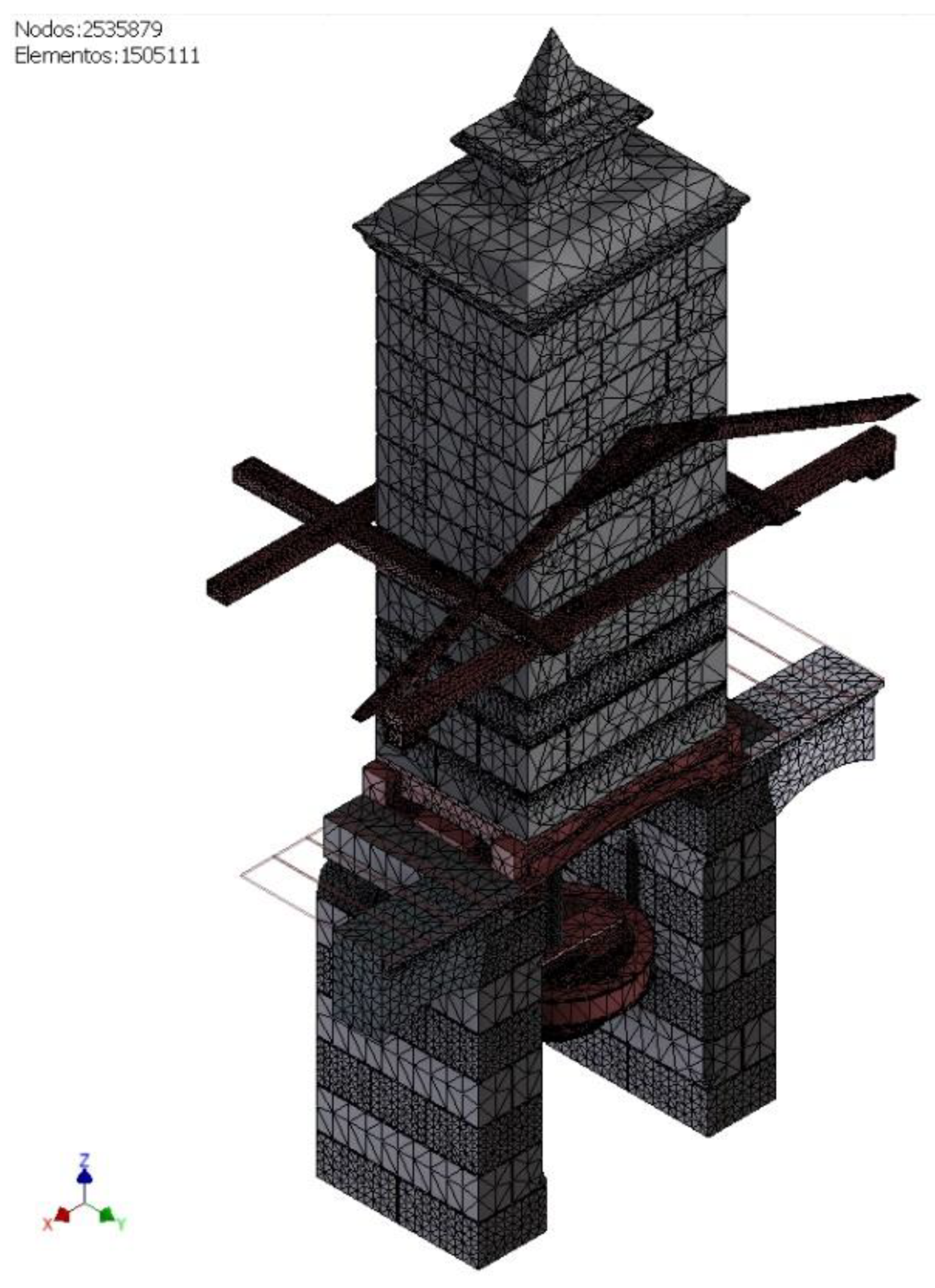
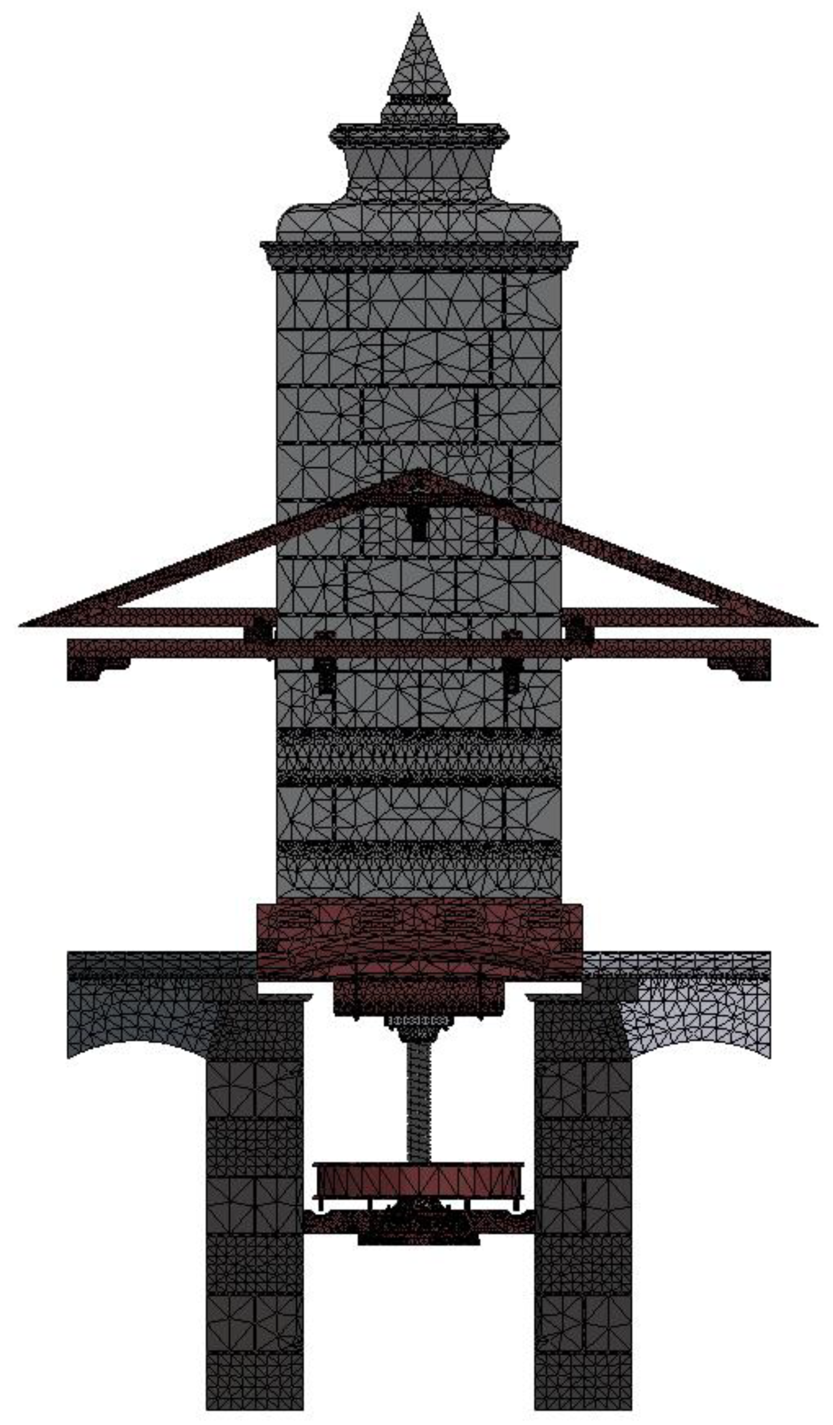
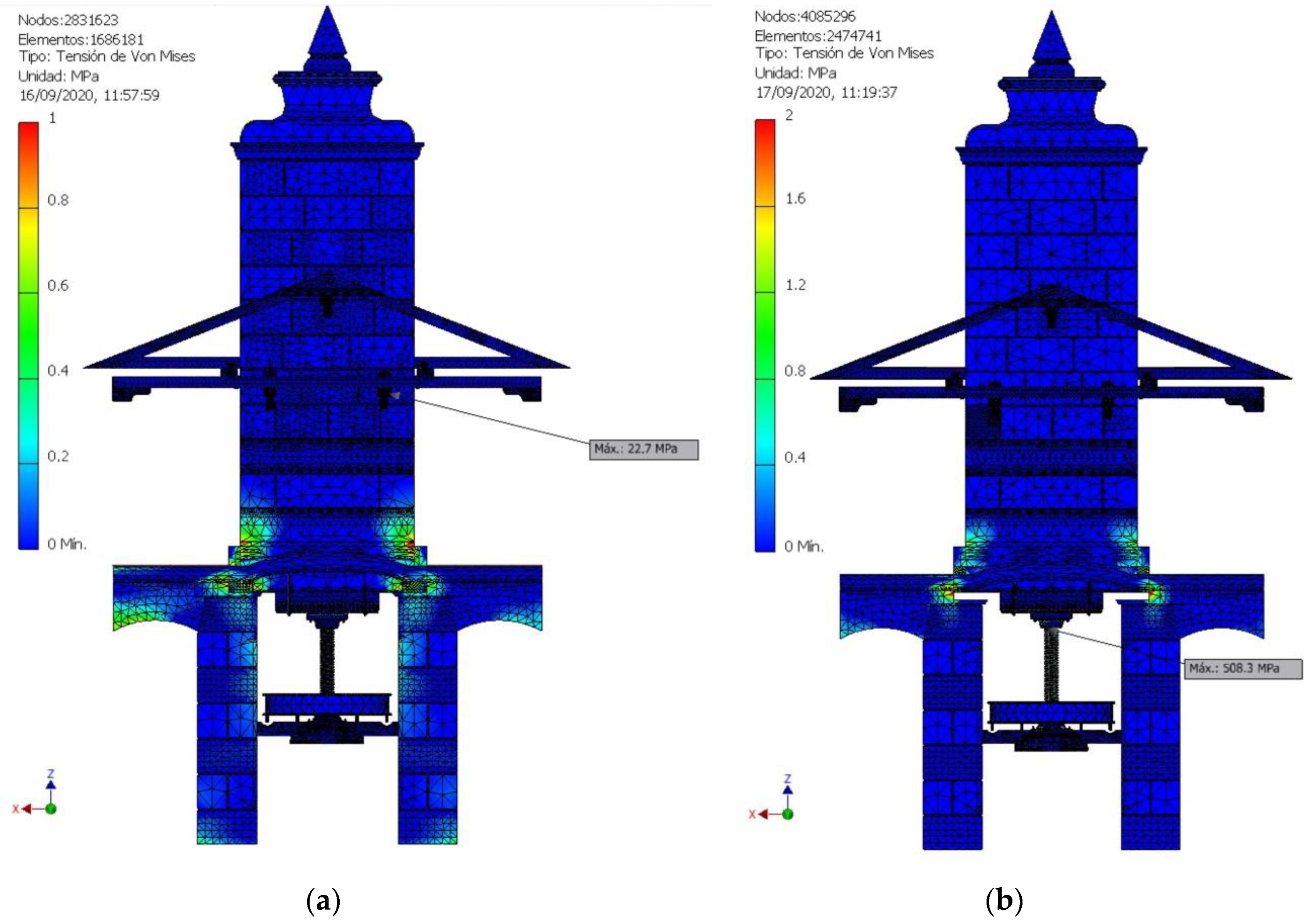
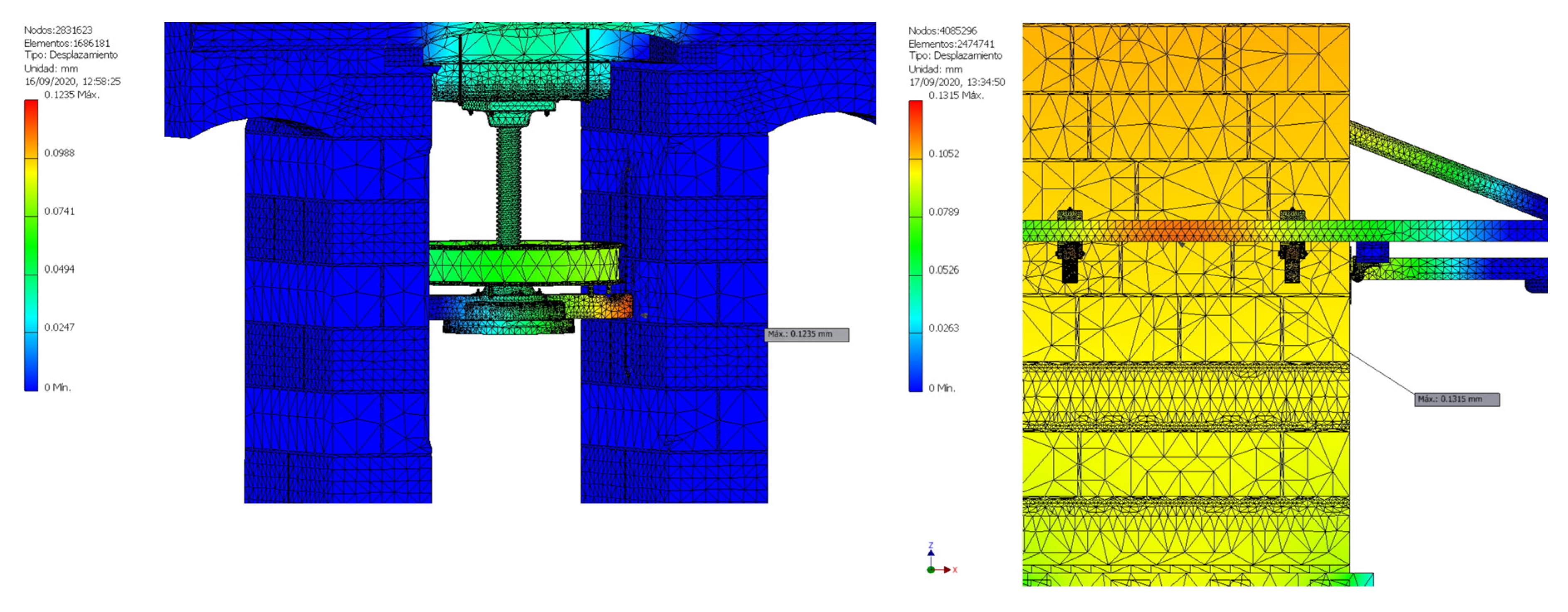
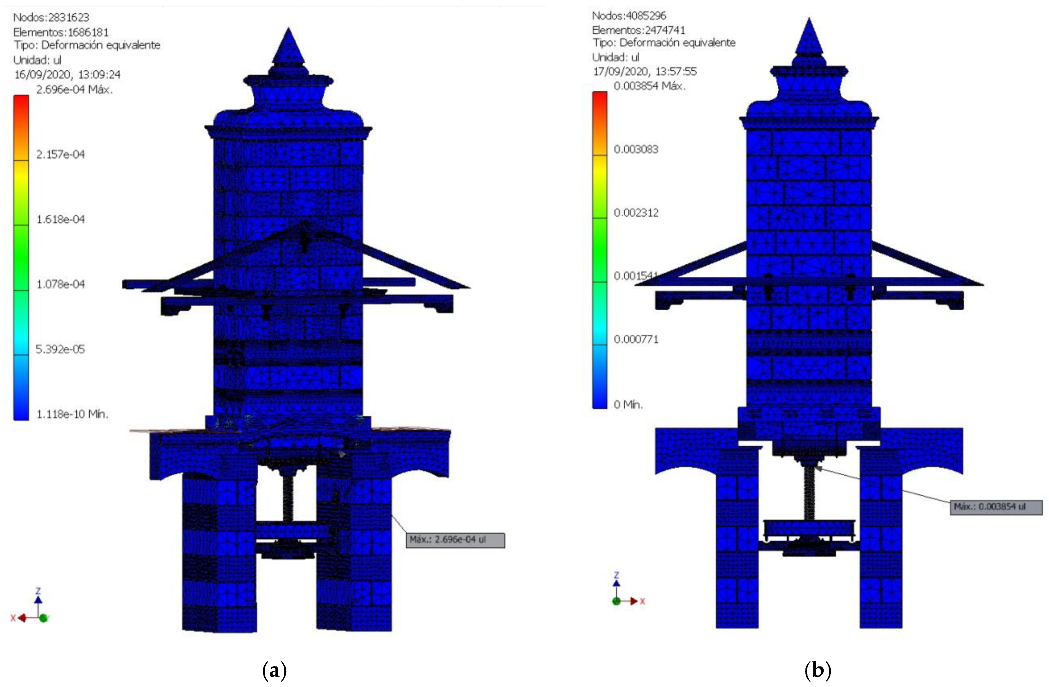
In the present research, a tetrahedral mesh has been obtained from the default values offered by the software. The mean size of the mesh element is 0.1 times the size of the bounding square, its minimum size is 0.2 times that of the mean element, and the variability factor between contiguous elements is 1.5. Finally, the maximum angle of rotation between tetrahedral surfaces is 60°. With these parameters, the mesh result obtained is precise, adjusting correctly to the geometry (Figure 12 and Figure 13).
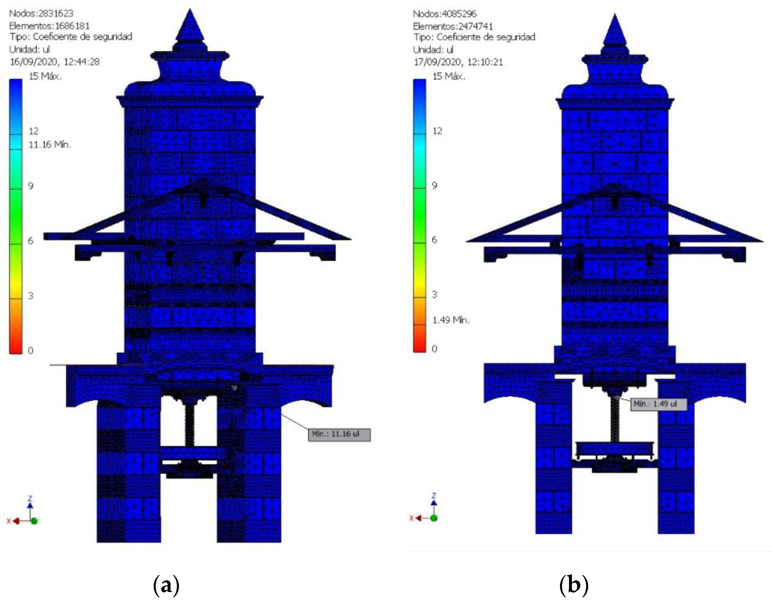
In Position 1 (tower supported on the pillars) a mesh with 1,505,111 elements and 2,535,879 nodes was obtained. However, in Position 2 (tower resting on the basket load), a larger mesh was obtained with 2,474,741 elements and 4,085,296 nodes, since when the tower is raised it presents a larger surface without contacts and more elements are needed to define its geometry.
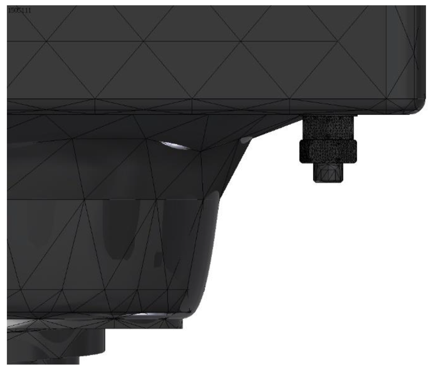
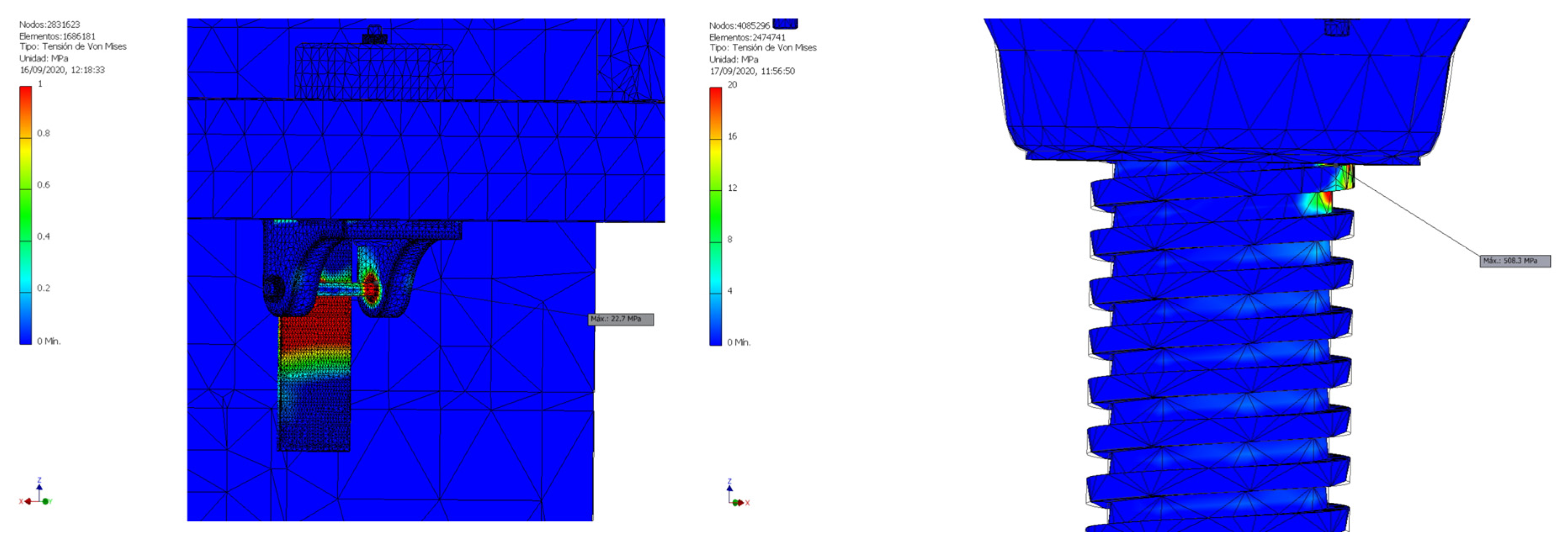
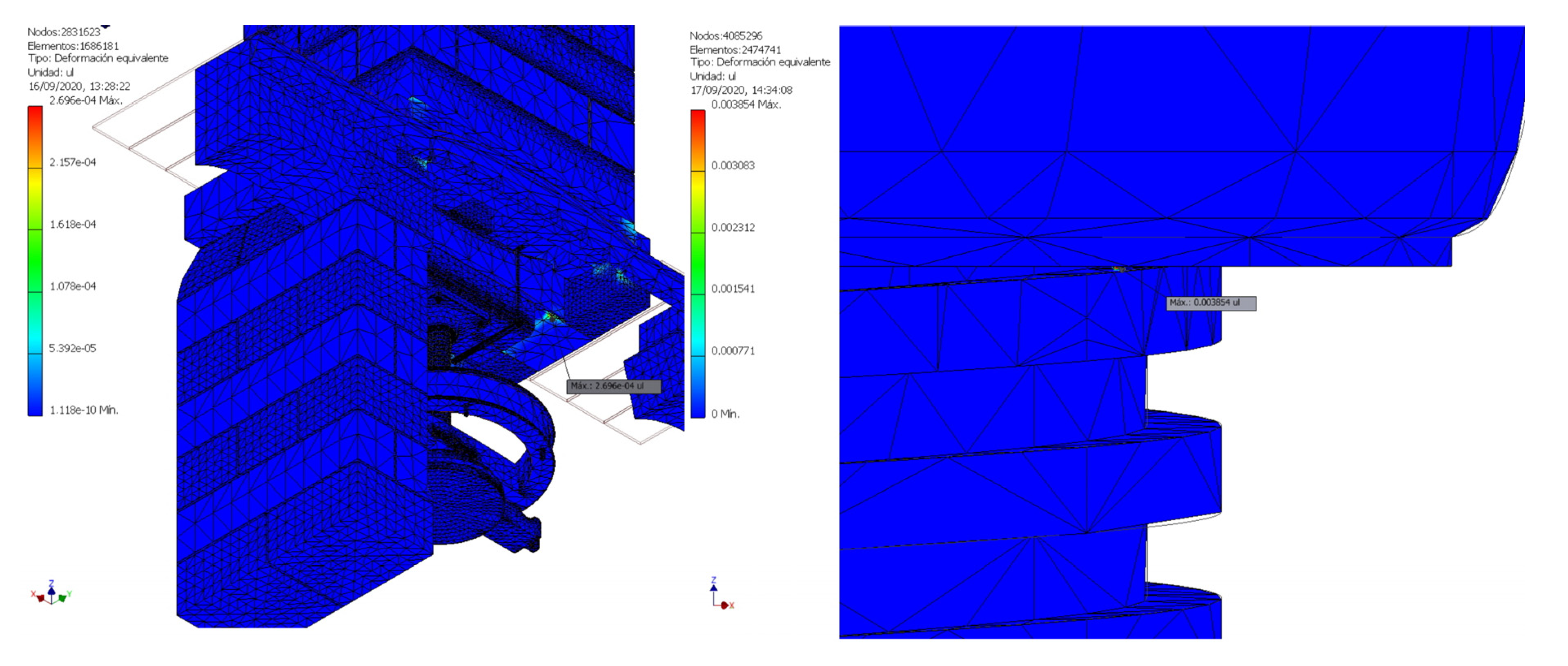
In addition, the complex geometry of some elements and the concentration of stresses that they are going to undergo forces a modification to be made in their mesh size, refining it. The meshing generated automatically by the software, which takes a mesh size proportional to the measure of the element, has caused some elements with a more complex and smaller geometry, such as the nuts or washers, to present a more refined mesh (Figure 14) compared to the rest of the elements, so it was not necessary to modify their size.

3. Results and Discussion

Once all the previous steps have been correctly carried out, the software allows the static analysis of the two limit positions by FEM to be performed, obtaining the von Mises stresses, the safety coefficient, the displacements and the equivalent deformation.
Von Mises stress is defined by [23]:
σ V M = ( σ 1 σ 2 ) 2 + ( σ 2 σ 3 ) 2 + ( σ 3 σ 1 ) 2 2
where σ1, σ2 and σ3 are the principal stresses.
In addition, Autodesk Inventor Professional enables modal analysis prior to static analysis, in which the model is subjected to a resonance study. Such modal analysis can discover errors without the need to perform a full simulation, since the static analysis requires as a precondition that the model does not behave as a rigid solid, which would mean that the resonance frequencies were close to 0 Hz.
On the interpretation of the results, it is convenient to point out that von Mises stresses were used instead of principal stresses. Although these show somewhat lower values than the principal stresses for the elements made of wood, it does not mean that these values are not valid, but they provide important indicative values, which, moreover, will not be too far from the value maximum stress in the most unfavorable direction.

3.1. Modal Analysis

Modal analysis of the two limit positions is performed in the absence of loads. To do this, the model is subjected to a resonance study in which the frequency of the wave is gradually increased until a considerable deformation is achieved in the different parts of the model. In static structures, the first deformations must appear above 2 Hz and must be relatively small, but it can also occur that the assembly has some part that does not behave statically. The results obtained in the modal analysis for the eight lower frequencies in which deformation occurs appear in Table 1.
In Position 1, the first two frequencies in which a deformation occurs are below 2 Hz, specifically at 1.34 and 1.55 Hz, and the element that has entered into resonance in both cases has been the pulley (Figure 15). This result makes sense since if the union between the nut and the bolt is observed in detail, it is not tight as it presents a bolt with a frusto-conical geometry (Figure 16), and therefore the nut presents some looseness with respect to the screw. The displacement produced at that frequency is, however, 0.00799 mm and therefore not relevant. The rest of the elements enter into resonance with frequencies above 2 Hz, so it can be concluded that a static analysis can be performed.
In Position 2, something similar happens; the first two frequencies of 0.78 and 1.13 Hz are below 2 and, therefore, there is an element that has come into resonance. In this case, it is the top of the tower, as could have been assumed a priori (Figure 17). When the tower is supported on the basket load there is no structural element that provides support; furthermore, the tower is free to move in the vertical direction. The rollers simply facilitate this movement, but in no way serve as a support; in fact, the part that has been called ‘mobile’ of the press could be analyzed independently with respect to which it has a structural purpose. However, resonance produces a deformation with a very small associated maximum displacement of 0.00596 mm. The rest of the frequencies are above 2 Hz and give results similar to those of Position 1, concluding that the static analysis can be performed.

3.2. Static Analysis

The FEM calculation procedure can lead to a different result depending on the starting point of the calculation. Each node of the mesh influences the calculation of the nodes of the adjacent meshes and therefore is not the same, as the method starts from one initial value or another. To obtain a result that is as close as possible to the real one, the software allows one to carry out a certain number of iterations in the simulation. On the other hand, every time it reaches a result it starts the calculation process again from that value and this causes the calculation process to take longer, meaning that convergence cannot be achieved in a reasonable time.
Autodesk Inventor Professional establishes as standard criteria parameters for convergence. Specifically, it focuses on a parameter (the von Mises stress has been chosen), which requires a maximum difference of 10% with respect to the previous result and sets the limit for the achievement of the result in eight iterations. In this way, if the result differs by more than 10% from the previous one, the calculation starts again from the values obtained, and if it completes the eighth iteration without a convergent result, it takes the last data obtained as the result.
Figure 18 shows the convergence study for both positions. For Position 1 (Figure 18a) of the study, a convergent result was obtained in the third iteration with a maximum von Mises stress value that differs by 5.619% from the previous one. For Position 2 (Figure 18b), the result has not been convergent. Between the sixth and seventh iteration there is a variation of 19.35%, but in the rest of the iterations it is higher. As in none of the iterations it is less than 10%, the value of the eighth iteration is taken, but being aware that the convergence rate of 50.38% will force us to be prudent in our conclusions regarding the analysis.
Table 2 shows the results of the static analysis for the main variables which will be explained below.

3.2.1. Von Mises Stresses

Figure 19 shows the von Mises stress distribution, showing that, in both positions, most of the elements work with very low stress values. In Position 1 (Figure 19a), the point of greatest stress occurs on the axis of the roller that helps the vertical movement of the tower, where the stress reaches a maximum value of 22.7 MPa. In Position 2 (Figure 19b), the maximum stress is located at the contact point between the screw and the nut, reaching the considerable value of 508.3 MPa.
If the elements where the tension is greater are observed in detail, several aspects are discovered (Figure 20). In Position 1, the elements designed to facilitate vertical movement (rollers) are perfectly positioned to the tower, so that it exerts an axial force that translates into a relatively high pressure on the roller axis. Today, these types of elements are designed with tolerances precisely so that they receive the force for which they were designed. In any case, a maximum value of 22.7 MPa (Figure 20a) is low for any element of the press regardless of the material with which the element is made. Without advancing conclusions, it is not too much of a risk to venture that for this position the press is clearly oversized.
On the other hand, Position 2 (Figure 20b) presents a particularly delicate point, the contact between the nut and the screw with a considerable value of 508.3 MPa, although, given that the elements in contact are made of cast iron, they do present a certain margin until reaching the elastic limit (758 MPa). As previously stated, Position 2 does not present the convergence of the von Mises stress, since the result of the eighth iteration is superior to that of the previous iterations. The actual von Mises stress at that point is probably somewhat lower, since previous iterations all show appreciably lower results. In any case, it is not a problem to adopt a value of 508.3 MPa as valid since, in any case, the press as a whole is being evaluated from the point of view of safety.

3.2.2. Safety Coefficient

The next variable to analyze is the safety coefficient at a point that represents the relationship between the von Mises stress at that point and the elastic limit of the material. The closer it is to the unit, the more compromised the element will be, even breaking if the material presents a safety coefficient lower than the unit. On the other hand, 15 is established as the maximum safety coefficient, although there are elements that could exceed this figure. Currently, designers work with optimal ranges between 2 and 4, so elements with values above this interval could be resized to optimize the model.
For Position 1, the tower press has a safety coefficient greater than 10 (Figure 21a). Specifically, it is the contacts between the tower (wooden frame) and the pillars that have a lower safety coefficient with a value of 11.16 (Figure 22a). Therefore, in this position it could be concluded that it is greatly oversized and that an extensive modification of the design of some elements would be desirable.
However, at Position 2 the analysis changes substantially. Figure 21b shows that in general, almost all the elements of the press have a safety coefficient close to 15, but when analyzing the model in detail (Figure 22b) it is observed that the point of contact between the screw and the nut presents a safety coefficient of 1.49. In this case, the point of maximum von Mises stress coincides with the point with a lower safety coefficient, and therefore any designer would consider changing the dimensions or geometry of this contact. To obtain a higher safety coefficient, it is not only necessary to increase the section of the screw, but, in this case, it is the geometry of the contact that could present a margin of improvement. Nowadays, the screw could be made of steel instead of cast iron, but, for the time in which it was designed, the best solution would have been to provide the screw thread with a greater dimension.
Figure 23 shows the second point with the lowest safety coefficient. This is the contact between the wood connector and the screw. This part presents a safety coefficient of 4.33 and therefore works within an efficient range and would not need to be replaced by another material. The rest of the elements work above this value and do not compromise the structure. Therefore, if the pillars on which the tower rests did not also have another structural function within the building itself (since the arches serve to transmit loads from the walls of the building to the pillars), they could also be resized.

3.2.3. Displacements

On the other hand, the maximum displacement of the elements is another of the most important aspects to study since an element whose displacement is too high could make some of the functions for which it is designed not possible or prevent the correct operation of the press as a whole.
In the present research, the maximum displacements, in either of the two positions, are very small. For Position 1, the element that undergoes the greatest displacement is the wooden pulley guide, while, in Position 2, the maximum displacement is located in the center of one of the beams of the guide structure that guarantee the vertical movement of the tower, which suffers some buckling (Figure 24 and Figure 25). In both cases, the displacement is less than 0.15 mm, so the wooden guide could affect the movement of the tower, as it does not leave the hole where it is housed in the pillars.

3.2.4. Equivalent Deformations

The last variable to study is the equivalent deformation, which is expressed as the relationship between the displacement of an element and its length, expressed as a percentage. Excessive deformation can cause damage to the material, which makes it unusable over time.
For Position 1, Figure 26a and Figure 27a show that the element that suffers the greatest deformation is the wooden connector that rests on the right pillar. The deformation of this element is 0.02696% with respect to the size of its length, so it is an acceptable value.
In Position 2, Figure 26b and Figure 27b show that the element that undergoes the greatest deformation is once again the point of contact between the nut and the screw, reaching a value of the equivalent deformation of 0.3854% of its length. This value is significantly higher than the previous one, but since it occurs in a metallic element, it does not represent a value to take into account.

4. Conclusions

The article shows the results of a static analysis carried out on the 3D model of a tower press for obtaining olive oil from the 20th century. For this, CAE techniques have been used thanks to the parametric software Autodesk Inventor Professional.
The tower press studied here is an original system used in ancient times to obtain olive oil from ground olive paste placed in a set of filter discs stacked one on top of the other (basket load) and forming what is called ‘cargo de capachos’. Thus, the tower with an enormous mass of approximately 46 t was allowed to fall perpendicularly onto this basket load, exerting a pressure of approximately 780 KPa. The tower press was a very robust device, large but with certain drawbacks such as the friction produced and the loss of verticality in the downward movement of the tower, which is why over time it was replaced by other technologically more advanced machines such as hydraulic presses.
The static analysis of the tower press has been carried out on two limit positions: The first, in a situation of rest, in which the tower rests on the pillars, and the second, in a situation of pressure on the basket load.
In the first position, the static analysis revealed that the maximum von Mises stress was 22.7 MPa. Furthermore, the minimum safety coefficient was 11.16 in the contact between the tower and the right pillar, well above the optimal range of values between 2 and 4. In addition, the greatest displacement would occur in the wooden guide that keeps the pulley in place, with a value of 0.123 mm and the equivalent deformation, also located in the support, with a value of 0.027% with respect to its length. These values confirm that, in this position, the tower press was clearly oversized.
However, in the second position, the results are not entirely conclusive. The software has not been able to obtain a convergent result for the von Mises stress, and the analysis of the iterations seems to indicate that the value adopted is well above what could be estimated as real. The maximum stress value is 508.3 MPa, lower than the elastic limit of cast iron (758 MPa), but remarkably high. The place where this value has been located is the contact between the screw and the nut into which it is screwed, due to the existence of a bolt that joins them with a frustoconical geometry. In this contact, the safety coefficient is 1.49, which, without compromising the material, does reveal a sizing problem. To solve this, it would have been convenient to resize the screw thread, giving it more robustness. The rest of the elements work with a safety factor above 4.33 so they are also clearly oversized, according to current criteria. Apart from this consideration the values of the displacements and the equivalent deformations are low, with results similar to those obtained in the first position with a maximum displacement of 0.1315 mm, located in the horizontal beam of the guide structure that guaranteed vertical movement of the tower, and a maximum equivalent deformation of 0.385%, located at the point of maximum von Mises stress (contact between screw and nut).
Moreover, the design of the olive oil mills and presses used in the last century for the most part did not take into account material resistance considerations, so they were clearly oversized from the point of view of safety, as has been verified in the present research.
As future research, and in order to analyze the dimensions of the pillars, the study would have to be completed with the structural analysis of the building that housed the tower press since, through the arches, the pillars that support the tower also work as a buttress.

Author Contributions

Formal analysis, J.I.R.-S., E.D.l.M.-D.l.F., M.J.H.-O. and D.H.-D.; investigation, J.I.R.-S. and E.D.l.M.-D.l.F.; methodology, J.I.R.-S., E.D.l.M.-D.l.F, M.J.H.-O. and D.H.-D.; supervision, J.I.R.-S.; validation, E.D.l.M.-D.l.F.; visualization, J.I.R.-S.; writing—original, draft, J.I.R.-S. and E.D.l.M.-D.l.F.; writing—review and editing, J.I.R.-S. and E.D.l.M.-D.l.F. All authors have read and agreed to the published version of the manuscript.

Funding

This research received no external funding.

Acknowledgments

This research has been supported by the results of the Research Project of the National Research, Development and Innovation Plan of the Government of Spain with reference HAR2009-06943. In addition, we thank the Museo de la Cultura del Olivo del Puente del Obispo (Jaén, Spain) for their kindness and collaboration in the aforementioned project by allowing a visit to their facilities. Also, we sincerely appreciate the work of the reviewers of this article.

Conflicts of Interest

The authors declare no conflict of interest.

References

  1. Tempesta, T.; Vecchiato, D. Analysis of the factor that influence olive oil demand in the Veneto region (Italy). Agriculture 2019, 9, 154. [Google Scholar] [CrossRef] [Green Version]
  2. Lia, F.; Zammit-Mangion, M.; Farrugia, C. A first description of the phenolic profile of EVOOs from the Maltese Islands using SPE and HPLC: Pedo-climatic conditions modulate genetic factors. Agriculture 2019, 9, 107. [Google Scholar] [CrossRef] [Green Version]
  3. Castellano, S.; Di Palma, A.; Germinara, G.S.; Lippolis, M.; Starace, G.; Scarascia-Mugnozza, G. Experimental nets for a protection system against the vectors of xylella fastidiosa well et al. Agriculture 2019, 9, 32. [Google Scholar] [CrossRef] [Green Version]
  4. Niavis, S.; Tamvakis, N.; Manos, B.; Vlontzos, G. Assessing and explaining the efficiency of extensive olive oil farmers: The case of Pelion peninsula in Greece. Agriculture 2018, 8, 25. [Google Scholar] [CrossRef] [Green Version]
  5. Cabanas, C.G.L.; Ruano_Rosa, D.; Legarda, G.; Pizarro-Tobias, P.; Valverde-Corredor, A.; Trivino, J.C.; Roca, A.; Mercado-Blanco, J. Bacillales members from the olive rhizosphere are effective biological control agents against the defoliating pathotype of verticillium dahliae. Agriculture 2018, 8, 90. [Google Scholar] [CrossRef] [Green Version]
  6. Zambon, I.; Serra, P.; Salvia, R.; Salvati, L. Fallow land, recession and socio-demographic local contexts: Recent dynamics in a Mediterranean urban fringe. Agriculture 2018, 8, 159. [Google Scholar] [CrossRef] [Green Version]
  7. Rodnick, D. Old olive oil mills and presses on island of Corfu, Greece–Essay on industrial archaeology and etnography of agricultural implements–Sordina, A. Am. Anthropol. 1972, 74, 1519. [Google Scholar] [CrossRef]
  8. Rojas-Sola, J.I. A review of the historical procedures for obtaining the oil olive in the oil mills from the engineering graphics. In The Olive Grove and Its Oil; Fundación del Olivar: Jaén, Spain, 2013; pp. 67–96. (In Spanish) [Google Scholar]
  9. Pequeño y Muñoz-Repiso, D. Elaboración del Aceite de Olivas; Imprenta de la Sociedad Tipográfica: Madrid, Spain, 1879. (In Spanish) [Google Scholar]
  10. Berges-Roldán, L.; López-Pérez, M. Caserías de Jaén. Arquitectura del Olivar; Estudio Tría: Jaén, Spain, 1973. (In Spanish) [Google Scholar]
  11. Vehbi, B.O.; Yuceer, H.; Hurol, Y. New uses for traditional buildings: The olive oil mills of the Karpas Peninsula, Cyprus. Hist. Environ. Policy Prac. 2019, 10, 58–82. [Google Scholar] [CrossRef]
  12. Yuceer, H.; Vehbi, B.O.; Hurol, Y. The conservation of traditional olive oil mills in Cyprus. J. Archit. Conserv. 2018, 24, 105–133. [Google Scholar] [CrossRef]
  13. Mazzotti, M. Enlightened mills–Mechanizing olive oil production in Mediterranean Europe. Technol. Cult. 2004, 45, 277–304. [Google Scholar] [CrossRef] [Green Version]
  14. Rojas-Sola, J.I. Ancient technology and computer-aided design: Olive-oil production in Southern Spain. Interdiscip. Sci. Rev. 2005, 30, 59–67. [Google Scholar] [CrossRef]
  15. Rojas-Sola, J.I.; De la Morena-de la Fuente, E. The conical stones olive oil mil: Analysis through Computer-Aided Engineering. Agriculture 2020, 10, 255. [Google Scholar] [CrossRef]
  16. Rojas-Sola, J.I.; De la Morena-De la Fuente, E. Agustin de Betancourt’s double-acting steam engine: Analysis through computer-aided engineering. Appl. Sci. 2018, 8, 2309. [Google Scholar] [CrossRef] [Green Version]
  17. Rojas-Sola, J.I.; De la Morena-De la Fuente, E. Agustin de Betancourt’s mechanical dredger in the port of Kronstadt: Analysis through computer-aided engineering. Appl. Sci. 2018, 8, 1338. [Google Scholar] [CrossRef] [Green Version]
  18. Rojas-Sola, J.I.; De la Morena-De la Fuente, E. The Hay inclined plane in Coalbrookdale (Shropshire, England): Analysis through computer-aided engineering. Appl. Sci. 2019, 9, 3385. [Google Scholar] [CrossRef] [Green Version]
  19. Zienkiewicz, O.C.; Taylor, R.L.; Zhu, J.Z. Finite Element Method: Its Basis and Fundamentals; Elsevier: Oxford, UK, 2013. [Google Scholar]
  20. Khoei, A.R. Extended Finite Element Method: Theory and Applications; Wiley: Chichester, UK, 2015. [Google Scholar]
  21. Song, C. The Scaled Boundary Finite Element Method: Introduction to Theory and Implementation; John Wiley & Sons: Hoboken, NJ, USA, 2018. [Google Scholar]
  22. Shih, R.H. Parametric Modeling with Autodesk Inventor 2016; SDC Publications: Mission, KS, USA, 2015. [Google Scholar]
  23. Gross, D.; Ehlers, W.; Wriggers, P.; Schröder, J.; Müller, R. Mechanics of Materials-Formulas and Problems: Engineering Mechanics 2, 1st ed.; Springer: New York, NY, USA, 2016. [Google Scholar]
Figure 1. Tower press.
Agriculture 10 00554 g001
Figure 2. Assembly plan of the tower press with an indication of all its elements.
Agriculture 10 00554 g002
Figure 3. (a) Position 1: Tower supported on the pillars and (b) Position 2: Tower supported on the basket load.
Agriculture 10 00554 g003
Figure 4. Fixed or structural part of the tower press.
Agriculture 10 00554 g004
Figure 5. Vertical axis capstan system.
Agriculture 10 00554 g005
Figure 6. Mobile part of the tower press.
Agriculture 10 00554 g006
Figure 7. Simplified model of the tower press for static analysis.
Agriculture 10 00554 g007
Figure 8. Elements with full movement restriction (fixed supports).
Agriculture 10 00554 g008
Figure 9. Movement restriction in the direction perpendicular to the face.
Agriculture 10 00554 g009
Figure 10. Manual contact between wooden frame and metal plate.
Agriculture 10 00554 g010
Figure 11. Gravitational force.
Agriculture 10 00554 g011
Figure 12. Automatic meshing obtained for the tower press (Position 1).
Agriculture 10 00554 g012
Figure 13. Automatic meshing obtained for the tower press (Position 2).
Agriculture 10 00554 g013
Figure 14. Detail of automatic meshing in elements of complex geometry.
Agriculture 10 00554 g014
Figure 15. Point of maximum displacement in the resonance study at 1.34 Hz (Position 1).
Agriculture 10 00554 g015
Figure 16. Screw attached to the nut by means of a frusto-conical bolt with some looseness.
Agriculture 10 00554 g016
Figure 17. Point of maximum displacement in the resonance study at 0.78 Hz (Position 2).
Agriculture 10 00554 g017
Figure 18. Convergence curve: (a) Position 1 and (b) Position 2.
Agriculture 10 00554 g018
Figure 19. Von Mises stress distribution: (a) Position 1 and (b) Position 2.
Agriculture 10 00554 g019
Figure 20. Location of the highest von Mises stress: (a) Position 1 and (b) Position 2.
Agriculture 10 00554 g020
Figure 21. Distribution of the safety coefficient: (a) Position 1 and (b) Position 2.
Agriculture 10 00554 g021
Figure 22. Location of the lowest value of the safety coefficient: (a) Position 1 and (b) Position 2.
Agriculture 10 00554 g022
Figure 23. Location of the second lowest value of the safety coefficient.
Agriculture 10 00554 g023
Figure 24. Displacement distribution: (a) Position 1 and (b) Position 2.
Agriculture 10 00554 g024
Figure 25. Location of maximum displacement: (a) Position 1 and (b) Position 2.
Agriculture 10 00554 g025
Figure 26. Distribution of equivalent deformations: (a) Position 1 and (b) Position 2.
Agriculture 10 00554 g026
Figure 27. Location of maximum equivalent deformations: (a) Position 1 and (b) Position 2.
Agriculture 10 00554 g027
Table 1. Frequencies of modal analysis.
F1F2F3F4F5F6F7F8
Position 11.34 Hz1.55 Hz3.88 Hz4.23 Hz4.53 Hz6.57 Hz7.08 Hz8.24 Hz
Position 20.78 Hz1.13 Hz2.15 Hz4.14 Hz4.26 Hz4.41 Hz4.52 Hz7.07 Hz
Table 2. Results of the static analysis.
Position 1Position 2
Maximum von Mises stress22.7 MPa508.3 MPa
Minimum safety coefficient11.161.49
Maximum displacement0.1235 mm0.1315 mm
Maximum equivalent deformation0.02696%0.3854%
Publisher’s Note: MDPI stays neutral with regard to jurisdictional claims in published maps and institutional affiliations.

