Article

Design and Analysis of an Automatic Shell Cracking Machine of Metohuayo (“Caryodendron orinocense Karst”) with a Capacity of 50 kg/h

by
Carlos Gianpaul Rincón Ruiz
,
Marco Antonio Tejada Cardeña
and
Juan José Jiménez de Cisneros Fonfría
*
Mechanical Engineering Department, Pontificia Universidad Católica del Perú, Lima 15088, Peru
*
Author to whom correspondence should be addressed.
Agriculture 2020, 10(11), 537; https://doi.org/10.3390/agriculture10110537
Submission received: 9 October 2020 / Revised: 31 October 2020 / Accepted: 2 November 2020 / Published: 9 November 2020

Abstract

:
This article presents the design and analysis of an automatic shell broken machine of seeds of Metohuayo (“Caryodendron orinocense Karst”) with a production capacity of 50 kg/h, considering manufacturing and maintenance of local facilities. Metohuayo is the fruit of a tree that grows in various jungle areas of Perú, and the Metohuayo oil is very requested because of its nutritional properties. Starting with these specifications, the design was developed according to the systematic approach established by the VDI-2221 standard, with seven basic steps to analyze the optimum design. Once the definitive project was reached and the commercial components were selected, finite element simulations were performed to analyze the strength of the shell broken system and to evaluate the strength and the dynamic response of the structural support of the machine components. Additionally, complementary experimental studies were performed, such as the analysis of the required force to break the shell or the measurement of their dimensions.

1. Introduction

The Amazon rainforest is a jungle with a huge variety of vegetation and wildlife; to date, more than 40,000 plant species and 3500 animal species are considered over the nine countries on the 7 million km2 of covered area. In this diversity, a special fruit named Metohuayo “Caryodendron orinocense Karst” is native to northwestern South America, particularly the Orinoco and Amazon river basins of Colombia, Venezuela, Ecuador, Perú, and Brazil (Figure 1a) [1]. The fruit, which has the same name as the tree, must be collected immediately after detaching because of its fast seed exposure and germination [2].
Metohuayo is characterized by a tough exterior shell that wraps and protects the seed inside (Figure 1b). Its seed is edible and consumed either directly or by extracting oil. The oil extract from seeds has a higher nutritional value in quantity and quality than the oil extracted from others fruits such as peanut, soybean, and olive; there is about 75% linoleic acid contained in Metohuayo seed, which gives a high concentration of polyunsaturated fats [1,2,3]. It can also be considered in the production of cosmetic products.
Figure 1. (a) Metohuayo’s growing regions [4]; (b) composition of the Metohuayo fruit [5].
Agriculture 10 00537 g001
Traditionally, the cracking process for Metohuayo and similar species used to be done by a group of people using human force. Because of the continuous rise in demand, small farmers need to increase their production capacity. This forced the creation of machines to automatically crack the fruit shell. In this sense, different shell cracking machines were developed specially for well-known nuts. The food processing industry proposed different machines to process the Cacay, Sacha Inchi, and macadamia fruits [6,7,8]. In South America, these machines are usually developed empirically for small farmers [9]. They improve their machines via trial and error, but they do not have a clear procedure for fabricating a machine which depends on the capacity requirements, local technology, and fruit mechanical characterization.
Moreover, it has been identified that there is no mechanical characterization available which quantifies the magnitude of force and strain required to crack the Metohuayo shell, information which is needed in order to design a machine specialized for the processing of Metohuayo fruits. Their complex geometrical characteristics vary; furthermore, an appropriate study is required to design a machine capable of processing different Metohuayo dimensions.
In this research, a novel shell cracking machine is proposed by applying the design methodology established in VDI-2221 [10]. The procedure proposed considers the problem through research about Metohuayo’s characteristics and mechanical characterization, presenting conceptual solutions evaluated on the basis of a list of requirements previously established. This led to the final project consisting of the development of a functional machine ready for fabrication. Computer-aided design/engineering (CAD/CAE) simulations were performed in order to evaluate the functionality of the machine proposed, extend the analysis previously done by hand, and improve the mechanical behavior, as well as dynamic response.

2. Materials and Methods

2.1. Mechanical Characterization of the Metohuayo Fruit

Metohuayo fruits, consisting of a shell and seed, are deposited into the machine (Figure 2). They can be found in different dimensions in terms of their length, width, and thickness [3]. As part of the problem clarification, the Metohuayo fruit needed to be mathematically represented in order to satisfy the space requirements and processing capacity. Hence, a sample of 100 Metohuayo fruits were measured, and the results are listed in Table 1.
It was identified that there is no mechanical characterization of this fruit which establishes the magnitude of force and strain required to crack its shell. In this sense, there are different types of test which can be used for this purpose, such as the well-known impact compression test, as well as other more difficult tests related to the production of shear stresses in the shell. According to the fracture mechanism proposed for the Metohuayo shell, compression tests were done at the material characterization laboratories of Pontificia Universidad Católica del Perú (Figure 3).

2.2. Application of the VDI-2221 Design Methodology to Determine the Conceptual Design

The VDI-2221 guideline [10] proposes a systematic approach to the process design of technical systems and products, which is very useful for the particular case of agriculture equipment. The methodology mainly consists of four phases: clarification of the problem, conceptual design, project development, and detailed design. The advantage of this guideline is the assessment of alternatives developed in each phase and the choice of the most optimal alternative on the basis of the designer’s criteria through their experience and knowledge.
The first phase is achieved by making a requirement list and determining the state of the art. It involves the characteristics that the project needs to achieve and characteristics that could be achieved. In order to meet the production demand, the design requirements were established by entrepreneurs who needed to process 50 kg per hour. The machine function covered fruit feeding to the separation of shell and fruit seed. Allowed materials were established according to the standards from the Food and Agriculture Organization of the United Nations (FAO) and World Health Organization (WHO). Local security standards were followed to assure operator safety and ergonomic operation.
The next step was to gather information from research on technologies and machines with the main function of separating the shell and seeds of different nuts such as macadamia nuts [11] in articles, patents, videos, and other information sources.
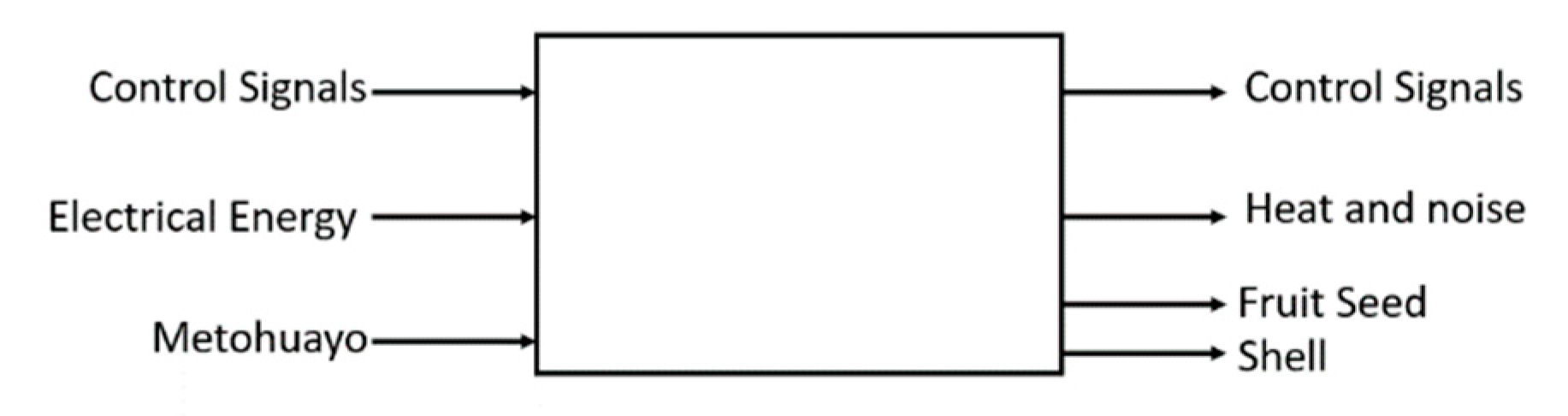
After the clarification of the problem, the phase of conceptual design was implemented to determine the optimal concept or solution principle. The machine is described as an overall function depicted as a black box in Figure 4.
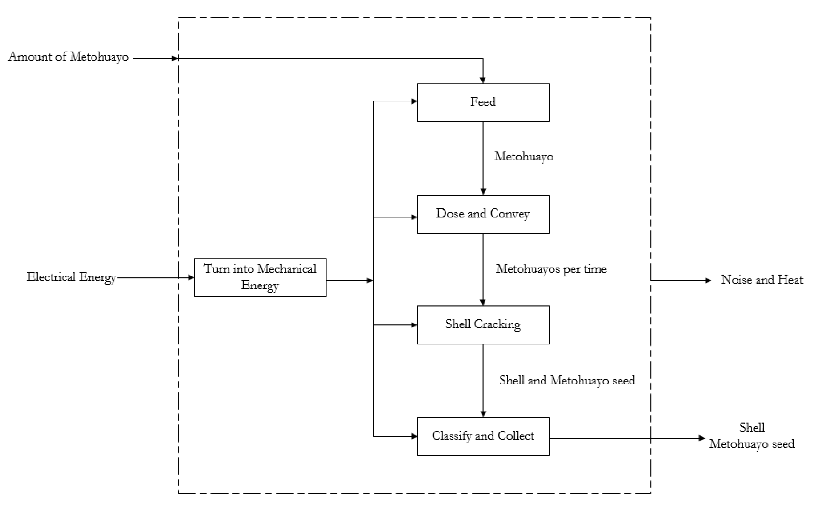
According to the aim, the strategy was to split the complex overall function into subfunctions. A sequence of operations was established to order the subfunctions. The function structure was represented in connected blocks due to the established sequence. Furthermore, some subfunctions could be grouped into one block which resulted in a number of alternative function structures. Figure 5 shows the optimal function structure composed of both individual and group subfunction blocks. The individual subfunctions were feed and shell cracking. The group subfunctions were dose and convey, shell cracking, and classify and collect.
Then, the functional elements performing the abovementioned blocks were determined through the research of components or systems satisfying the solution principles [12]. 
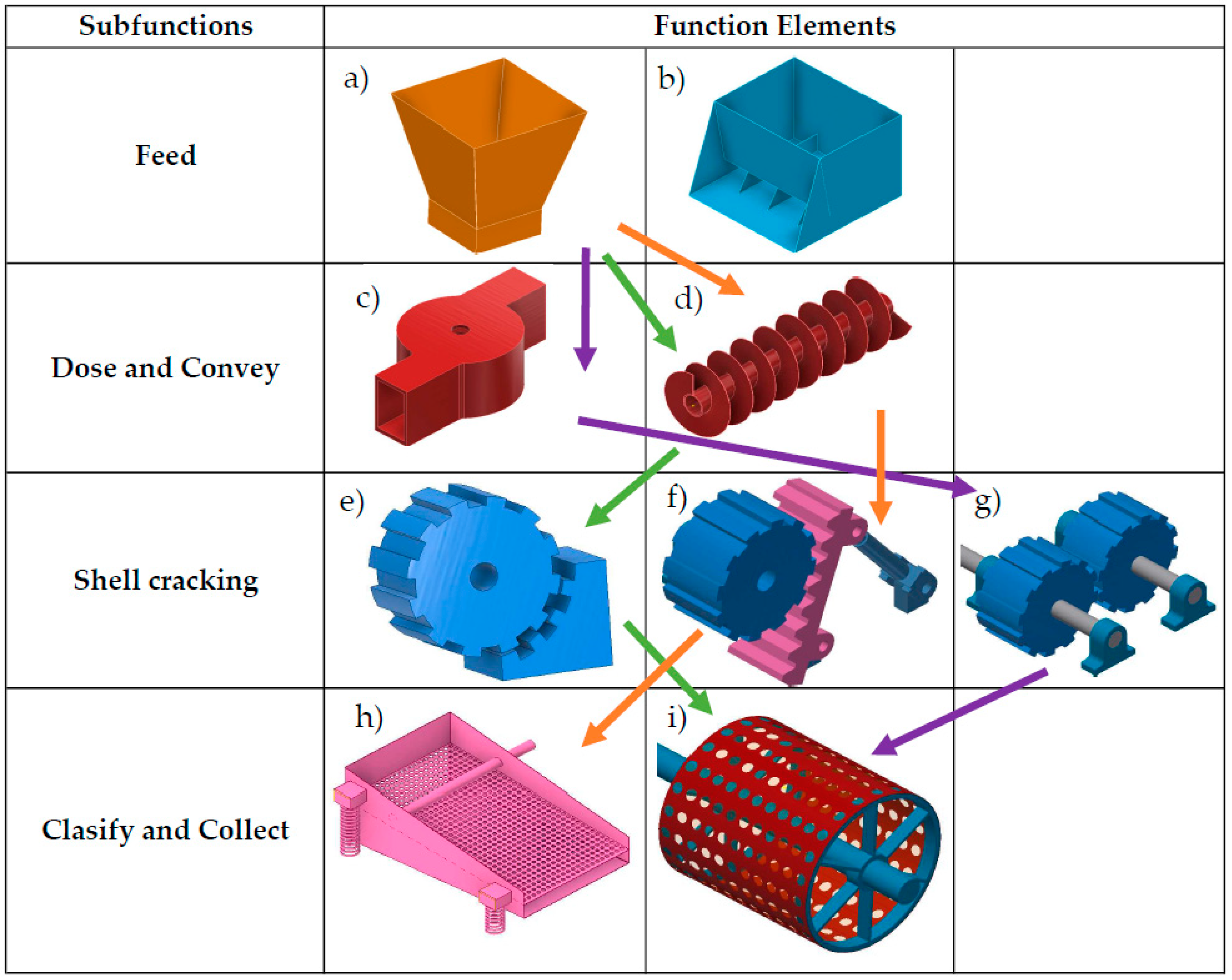
Figure 6 shows a morphological table in which the subfunctions are listed in the first column of the table and the functional elements are presented in each respective row. The elements are linked by arrows, resulting in alternative solution concepts. In this sense, the morphological table provides a large number of possible solutions which is both an advantage and a disadvantage of this method since the number of layouts must be reduced according to the requirements previously established [
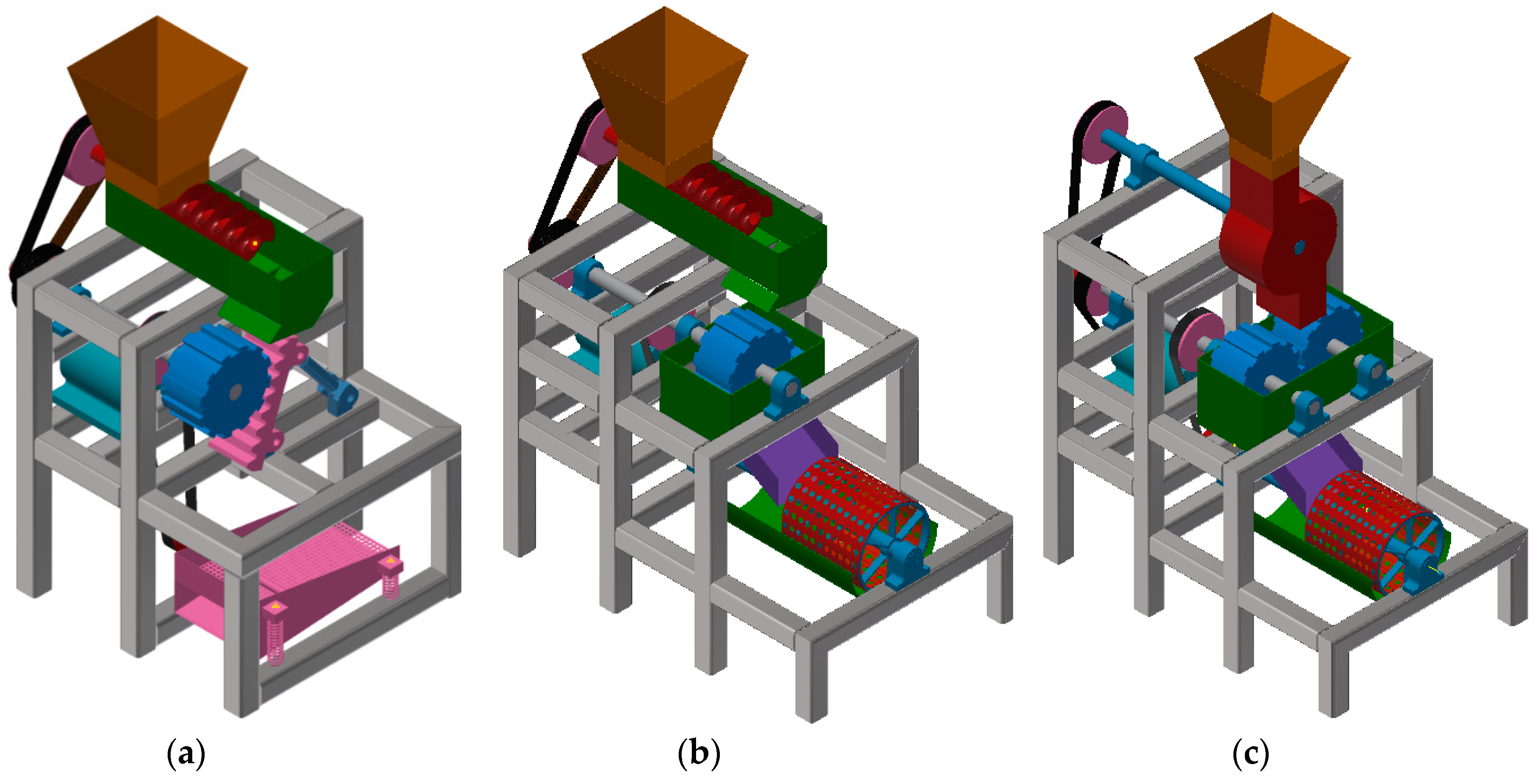
13]. In the current design, the best three concepts were chosen according to the requirements of farmers and the advantages of the functional elements presented as combinations. Three-dimensional (3D) freehand drawings were generated to visualize the alternatives. The schematic concepts made with the program Autodesk Inventor are shown in Figure 7. The determination of the optimal concept was based on economic and technical criteria such as minimum components, fabrication feasibility, design safety, and requirement accomplishment. 
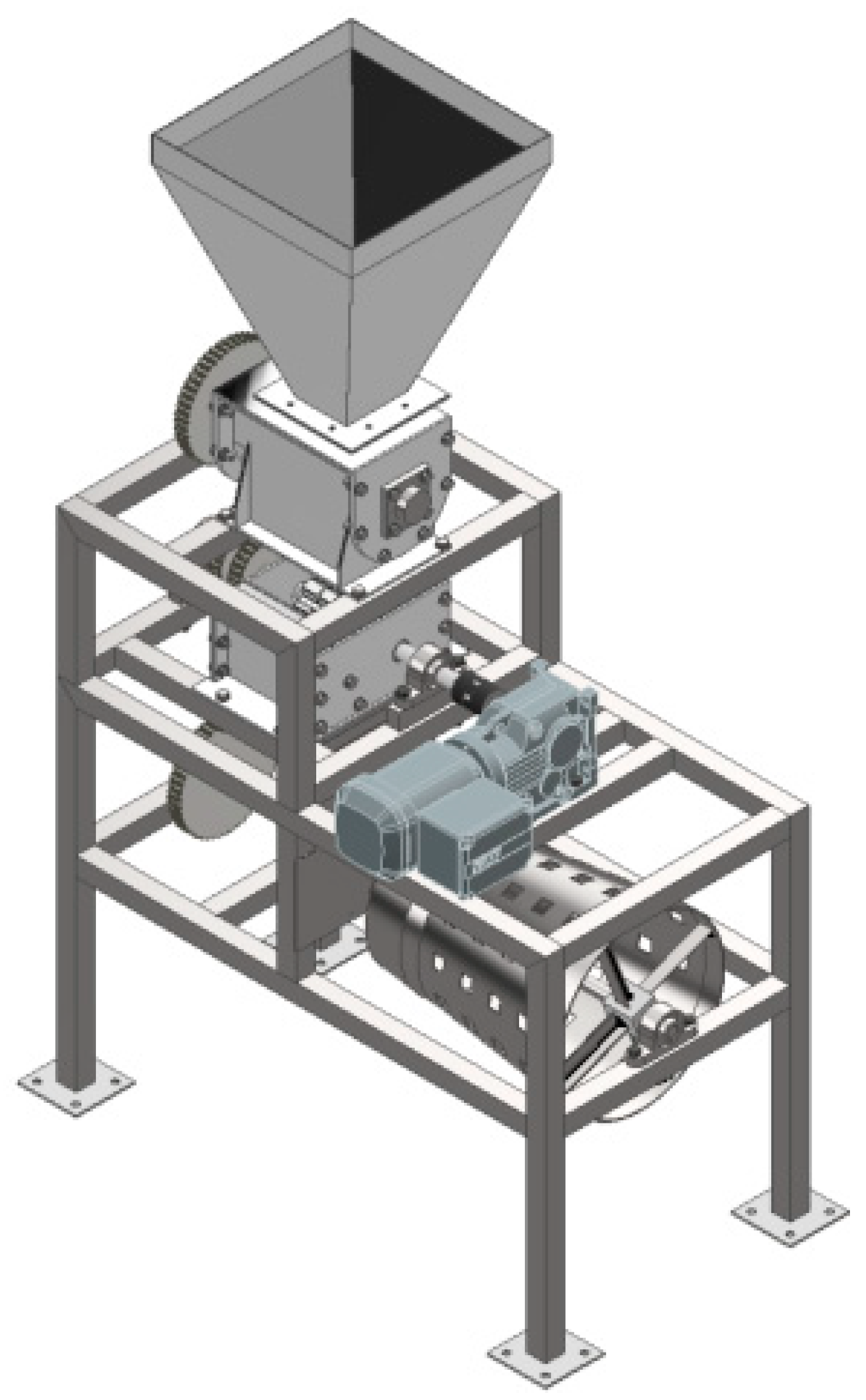
Figure 7b shows the optimal solution concept consisting mainly of a chute (Figure 6a), screw conveyor (Figure 6d), toothed wheel with a tilted toothed wall (Figure 6f), and rotating screen (Figure 6i).
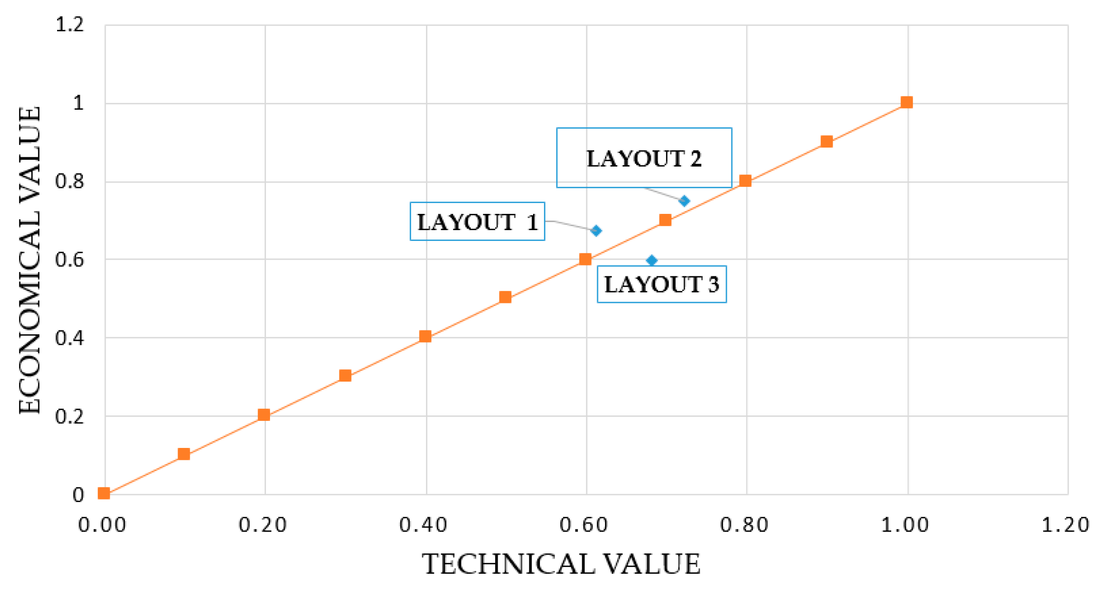
After the determination of the optimal solution concept, the phase of project development continued. The third phase was characterized by the development of preliminary layouts that differed from each other because of the power transmission and the arrangement of functional elements. Rough calculations according to the strength of materials were carried out in order to determine the dimensions of components, as well as the total power required by each component to determine the total power required by the electrical motor. This is discussed in Section 2.3. Three-dimensional freehand drawings and three preliminary layouts were generated. The selection of the optimal preliminary layout depended on the technical and economic criteria listed in Table 2 and Table 3, respectively. This procedure allowed evaluating the solutions as a function of different criteria, where a better performance corresponded to a higher mark, and weighting factors were established for each criteria according to the project requirements [13]. In Table 2 and Table 3, g is the weighing factor, p is the mark assigned from 0–4 depending on the performance achieved for each criterion, and gp is their product. The ideal solution represents the maximum grade possible assigned as 4 for each criterion, whereas the ratios between the sum of gp from the ideal solution column and the sum of gp from the other solutions correspond to the technical value xi or economic value yi. The best solution results from an equilibrium between both technical and economic criteria, which corresponds to the nearest solution to the 45° line (Figure 8). Then, the layout was improved since the location of the components, materials, frame, and dimensions was defined. The assembly of the components and the final project were carried out using the program Autodesk Inventor (Figure 9).
The final phase was the design consisting of the development of engineering drawings and the 3D model with the use of computer-aided design (CAD) and computer-aided engineering (CAE) software, as discussed in detail in Section 2.5 and Section 2.6, respectively.

2.3. Design and Component Sizing

The procedure presented above allowed us to obtain different and creative solution concepts from the functional and physical principles. However, the machine’s morphology and aesthetics were not sufficient to design a machine, and dimensions needed to be calculated in order to get a good performance.

2.3.1. Fracture Mechanism

Figure 10 schematically shows the proposed fracture mechanism. It consisted of a toothed cylinder whose profile shape was experimentally determined for cracking macadamia nuts [11]. This fruit is similar to the Metohuayo in terms of their dimensions and the force required to crack their shells. The torque on the shaft required could be calculated by using Equation (1), where F is the force provided by the mechanical characterization in N, rgear is the radius from the center to the contact point in meters, and nmetohuayos is the number of Metohuayos cracked at the same time.
It can be seen that there is an angle between the force and radius, but the maximum torque possible was considered to occur when this angle is 90°; thus, the expression was reduced to Equation (1).
T f . m = F · r g e a r · n m e t o h u a y o s
Power requirements for the shaft could be calculated using Equation (2), where Pf.m is the power required for the fracture mechanism, Tf.m is the torque in N·m, and ω1 is angular velocity of the shaft in rad/s.
P f . m = T f . m · ω 1

2.3.2. Screw Conveyor

According to the concept evaluation, a screw conveyor was selected to dose a quantity of Metohuayos from the chute to the fracture mechanism inside the machine. This dose corresponded to the capacity of 50 kg per hour previously established by small farmers’ requirements. Equation (3) allows determining the power required to achieve this capacity in a horizontal position [14], where Ps.c is the power required in kW, L is the screw length in m, c is the material factor in kW∙h/ton, Qme is the mass per unit of time expressed in ton/h, and Dh is the screw external diameter in m.
P s . c = L ( c Q m e 367 + D h 20 )
Then, the torque required for screw conveyor could be calculated using Equation (4), where Ts.c is the torque on the shaft in N·m, and ω2 is the angular velocity of its shaft in rad/s.
T s . c = P s . c ω 2

2.3.3. Rotating Screen

The dynamic behavior of the particles inside the screen during operation is very complex to determine analytically; hence, some suppositions were made in order to estimate the power required in a critical case corresponding to the start-up because of the inertial forces produced.

Screen Rotational Inertia

The screen could be modeled as a truncated cone surface whose rotational inertia could be calculated using Equation (5), where Iscreen is the screen rotational inertia in kg∙m2, mscreen is the screen mass, rmax is the maximum cone radius in meters, and rmin is the minimum cone radius in meters.
I s c r e e n = 3 10 m s c r e e n ( r m a x 5 r m i n 5 ) ( r max 3 r min 3 )

Shaft Rotational Inertia

The rotational inertia of the solid shaft could be calculated using Equation (6), where Ishaft.3 is the shaft rotational inertia in kg∙m2, mshaft.3 is the shaft mass in kg, and dshaft.3 is the shaft diameter in meters.
I s h a f t .3 = 1 4 m s h a f t .3 d s h a f t .3 2

Metohuayo Mass Rotational Inertia

The critical case analyzed consisted of part of the mass deposited inside the screen which produced an inertial force. This inertia could be modeled as punctual mass inertia, Equation (7), where Ime is the rotational inertia of the Metohuayos in kg∙m2, mme is the Metohuayo mass in kg, and rcone is the average radius in meters. In this calculation, the magnitude of mass corresponded to half the mass processed in an hour, due to the screen tilt.
I m e = m m e r c o n e 2
Total inertia could be calculated using Equation (8) as the sum of each component’s rotational inertia.
I r . s = I s c r e e n + I s h a f t .3 + I m e
A constant angular acceleration was assumed to reach the operation angular velocity of 60 rpm in 2 s. Furthermore, the torque required to contrast these inertial forces was calculated using Equation (9), where Tr.s is the torque required in N∙m, Ir.s is the rotating screen inertia in kg∙m2, and αr.s is the angular acceleration of the shaft in rad/s2.
T r . s = I r . s α r . s

2.3.4. Power Requirement

Each component described needs a quantity of mechanical power in a determined angular velocity to operate. The drive system consisted of a main shaft mounted for the fracture mechanism with two pulleys. Each pulley was linked by a toothed belt transmission to the screw conveyor shaft and rotating screen shaft. Total power could be calculated using Equation (10) as the sum of each component’s required power considering the belt transmission efficiency, where Ps.c is the power for the screen conveyor, Pgear is the power for the fracture mechanism, Pr.s is the power for the rotating screen, and ηbelt is the transmission efficiency.
P t o t a l = P s . c η b e l t + P g e a r + P r . s η b e l t

2.4. Dynamic Modeling of the Machine

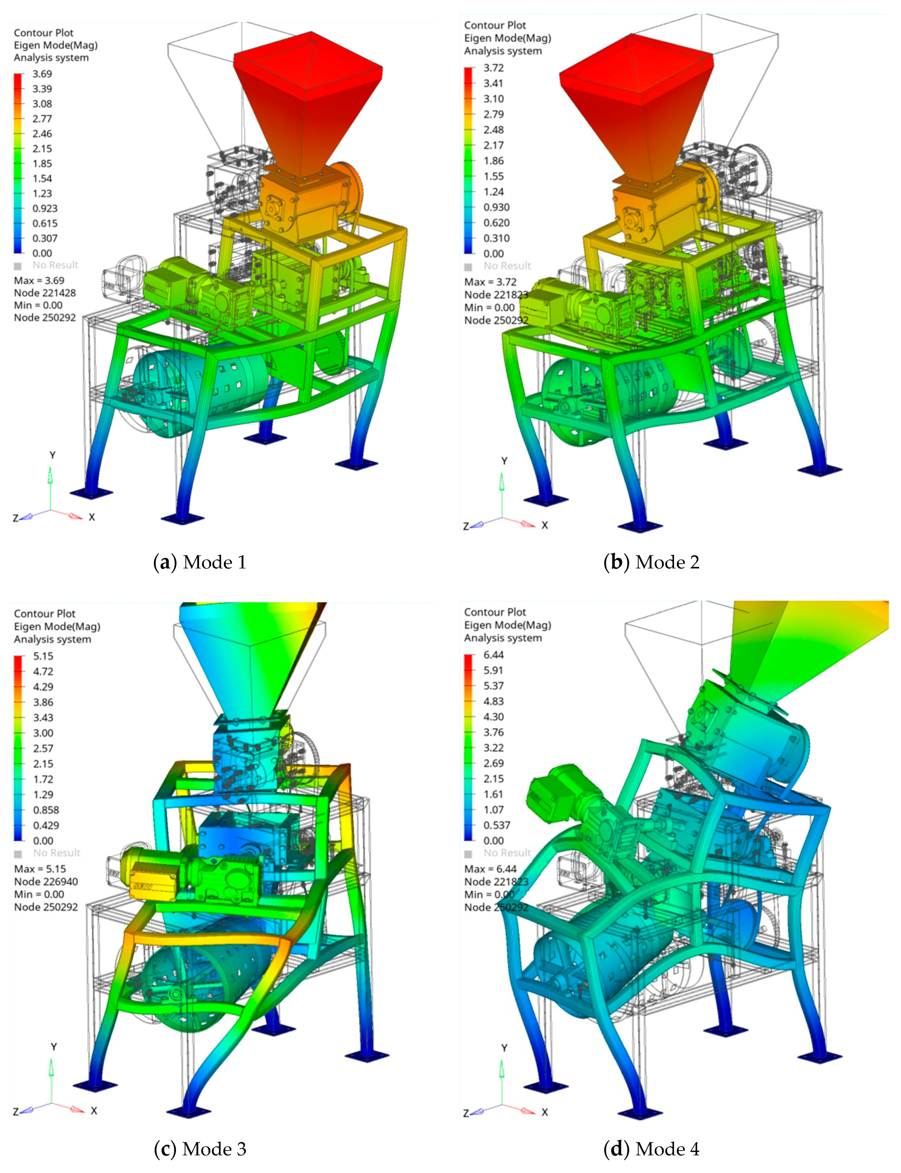
For each material’s mechanical properties, a system has its own dynamical characteristics depending on mass, stiffness, damping, and boundary conditions. These parameters together establish the natural frequencies of the system, in this case, the machine. If there is an excitation force near to one of these natural frequencies, high vibration amplitudes are produced and, when both coincide, a phenomenon known as resonance occurs [15]. In this sense, it must be verified that each excitation frequency is sufficiently far from the natural frequency. In the same way, the forces related to each excitation frequency must not occur in the plane of their respective modal shape.
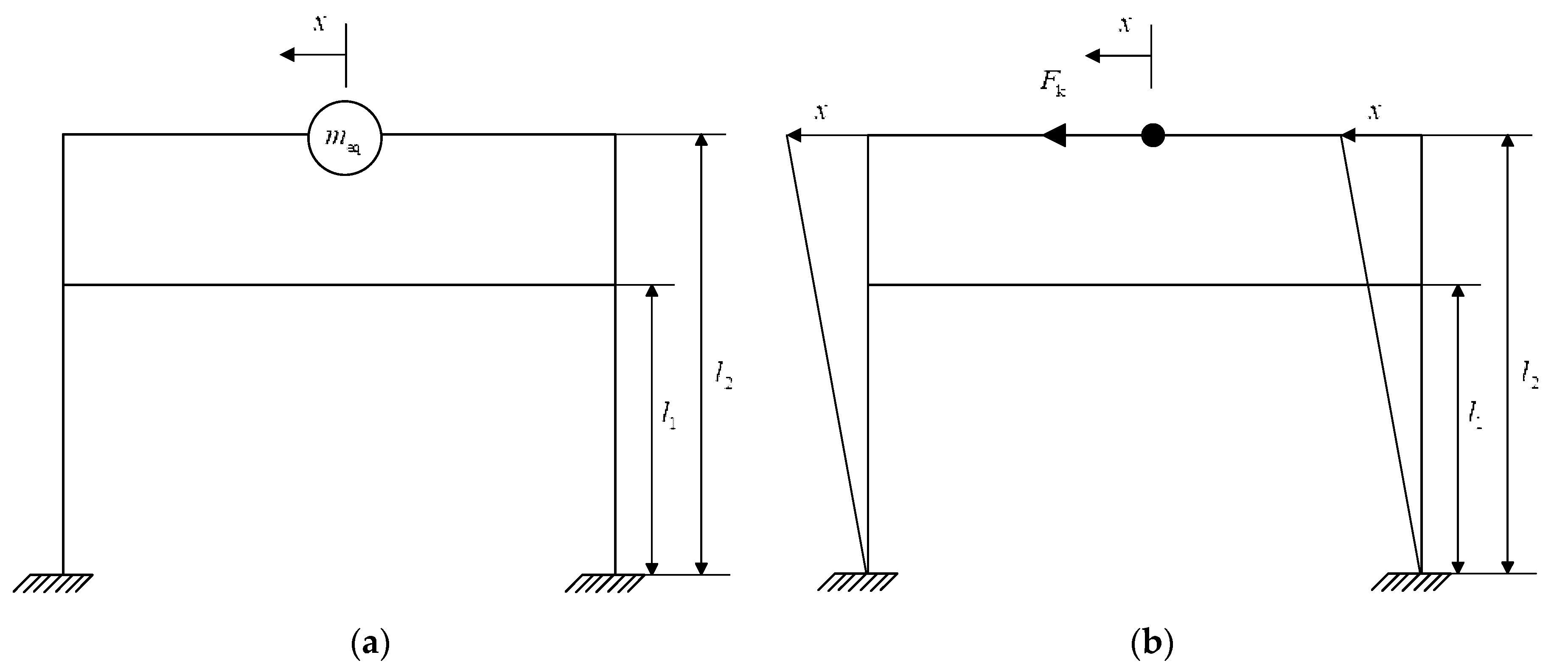
In order to calculate the natural frequency of the machine designed, an analytical model was proposed. In the first approach, a one degree of freedom (1DOF) model was developed (Figure 11a). The equivalent mass meq corresponded to the sum of mass above the second level of the structure because of the mass distribution along the machine. The frame for the machine was modeled as four columns united by eight beams, with four on each level. Damping was neglected in this model, and small displacements x were assumed on the second level on top of the structure.
In the operational conditions of the machine, dynamical forces are produced through the interaction between mass equivalent and frame. In order to analyze the dynamics corresponding to the horizontal direction, the stiffness in this direction needed to be calculated. The stiffness is the relationship between a force applied and the displacement produced in that direction. In this sense, a force Fk produced a displacement x in the horizontal direction (Figure 11b). The displacement was calculated using the beam deflection theory. The columns were analyzed as fixed beams, with the upper and lower beams producing a force because of their interaction with the columns; thus, the superposition principle was used, resulting in Equation (11), where E is the Young modulus of the material in MPa, I is the inertial moment from the section of the column used in m4, l1 is the length from the ground to the lower beam in m, and l2 is the length from the ground to the upper beam in m.
x = F k E I ( l 2 3 12 l 2 l 1 2 12 l 2 2 l 1 8 )
Then, the stiffness keq in N/m corresponding to the horizontal direction is the relationship between Fk and x (Equation (12)).
k e q = E I ( l 2 3 12 l 2 l 1 2 12 l 2 2 l 1 8 )
The differential equation representing the movement of the machine along the horizontal direction with no external forces had the form shown in Equation (13), where meq is the equivalent mass in kg, and keq is the equivalent stiffness corresponding to the displacement x. The natural frequency of the machine ω modeled with 1-DOF was estimated using Equation (14).
m e q x ¨ + k e q x = 0
ω = k e q m e q

2.5. Computer-Aided Design (CAD) of the Machine

According to the basic specifications and calculations developed and exposed in previous points, a detailed three-dimensional computer-aided model of the complete machine and the support was modeled. Autodesk Inventor software was considered to create a digital prototype of a general 3D mechanical solid modeling application, commonly used in the design of machinery for different sectors, such as the construction, automotive, or agriculture sectors. All components of the machine (structural profiles, mechanical devices, and standard and commercial components) were assembled and positioned in a unique model, where the geometric and manufacturing information was obtained, such as part and assembly drawings, bill of materials, or models to generate toolpaths in manufacturing applications (CAM software). The software also allowed the export of geometry in standard formats recognized by CAE software.
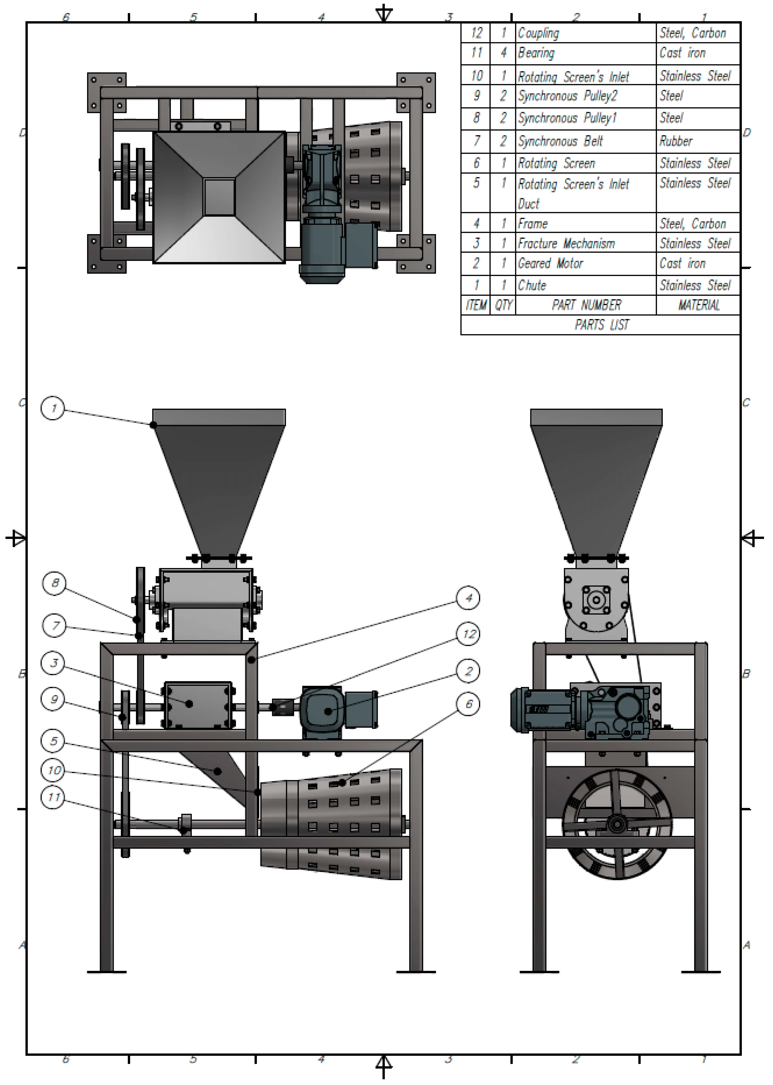
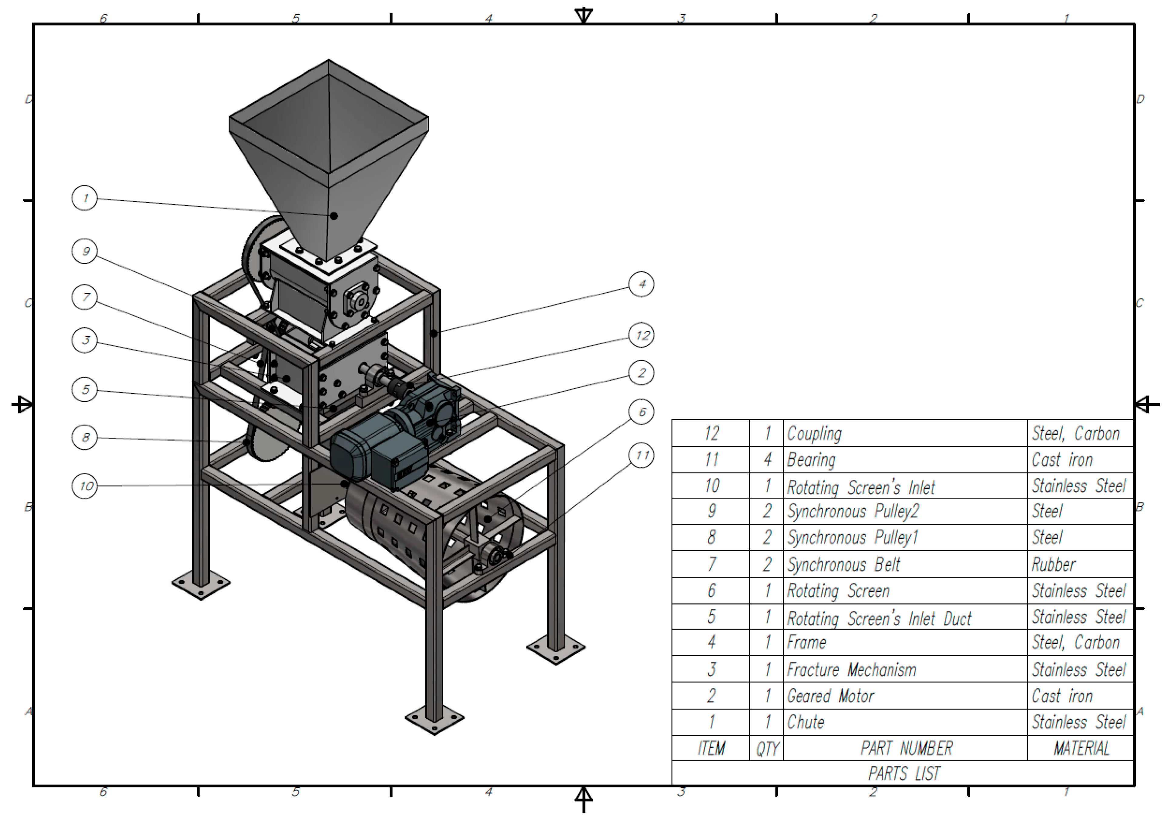
Figure 12 shows the assembly plan of the shell cracking machine and its four main components. Figure 13 shows main views of the machine. Each was developed by following the structure of functions in the conceptual design phase. As can be seen, a modular design was favorable in order to facilitate fabrication, maintenance, and assembly.
Figure 14 shows a section of the machine describing the Metohuayo fruit processing. The operation started with Metohuayo fruits being fed through a chute fed. The screw conveyor controlled the quantity and velocity of processing according to the capacity 50 kg/h. Fruits were then sent to the fracture mechanism composed of a toothed cylinder and a toother wall with variable clearance provided by the wall tilt. This allowed processing different dimensions of Metohuayo fruits according to the sample analyzed.
When the fruits were cracked, they were divided into shell and seed, which needed to be separated in order to get only the seeds. Under the fracture mechanism, there was a duct leading the cracked fruits to the rotating screen. This rotating screen had a truncated cone shape to generate a tilt for the shells to drop to the end.

2.6. Computer-Aided Engineering (CAE) of the Machine

Conventionally, the engineering product development process employed a design–build–test philosophy, where the “optimum” solution was reached via a trial-and-error sequence, and where the experience of the designer related to the product was decisive. Simulation-based design methods, as defined in [16], considerably reduced this design process, in terms of time and cost, and the concept of concurrent engineering, for example, is today considered in product design. In these techniques, the task of carrying out experimental tests is displaced by the simulation through numerical techniques of the different physics involved in the problem which is the object of study by the designer.
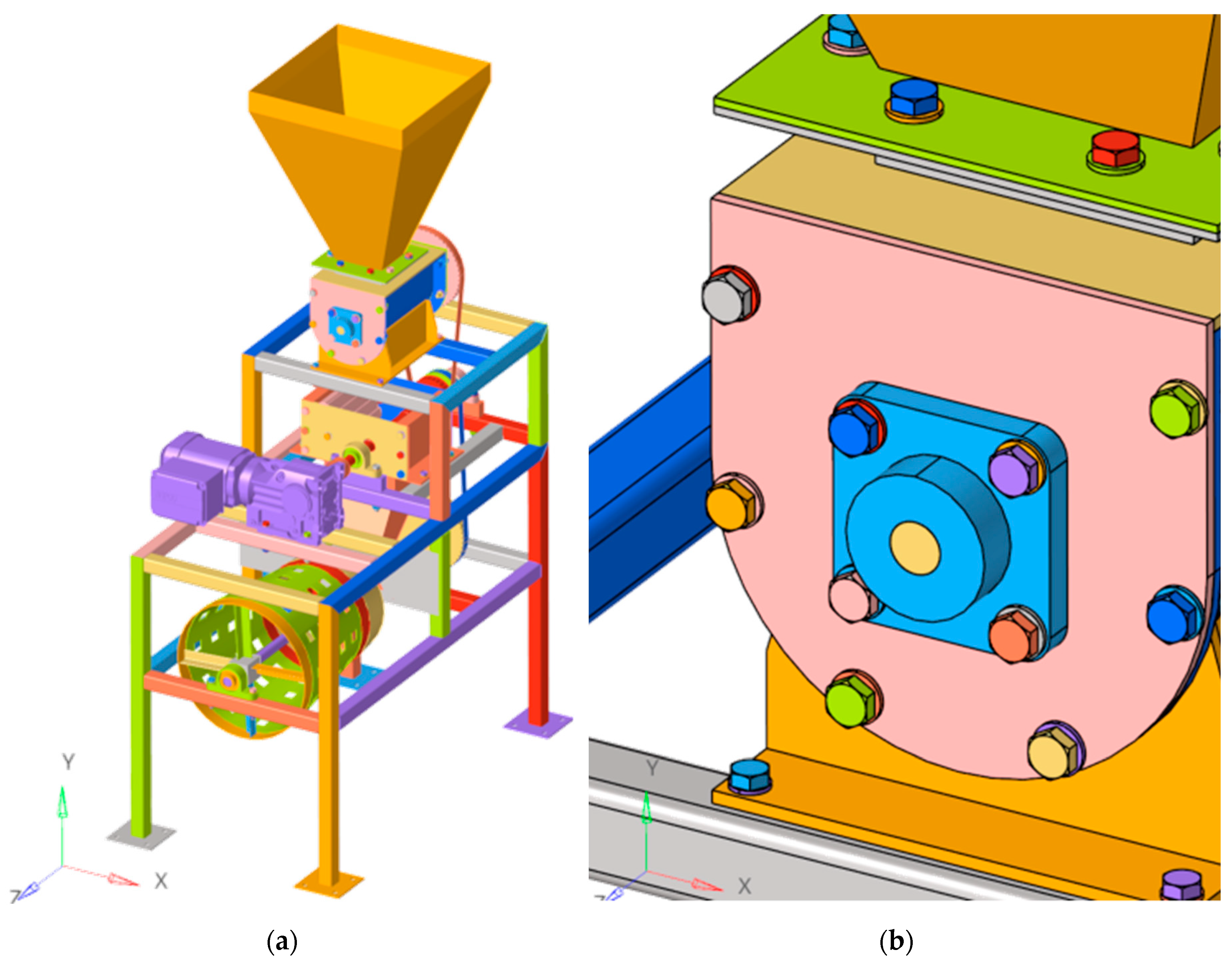
For the CAE simulation, the Altair Hyperworks simulation platform was considered, in which the preprocessing and postprocessing stages were addressed. The CAD three-dimensional model was taken as a starting point (Figure 15a), whose components were pre-dimensioned and selected according to basic calculations. In this model, some simplifications were implemented in the bearing supports (Figure 15b), since these subsets included all the elements that made them up (balls, cages, raceways, seals, etc.), which complicated their analysis. The difference in results at the level of the overall behavior of the structure was imperceptible.
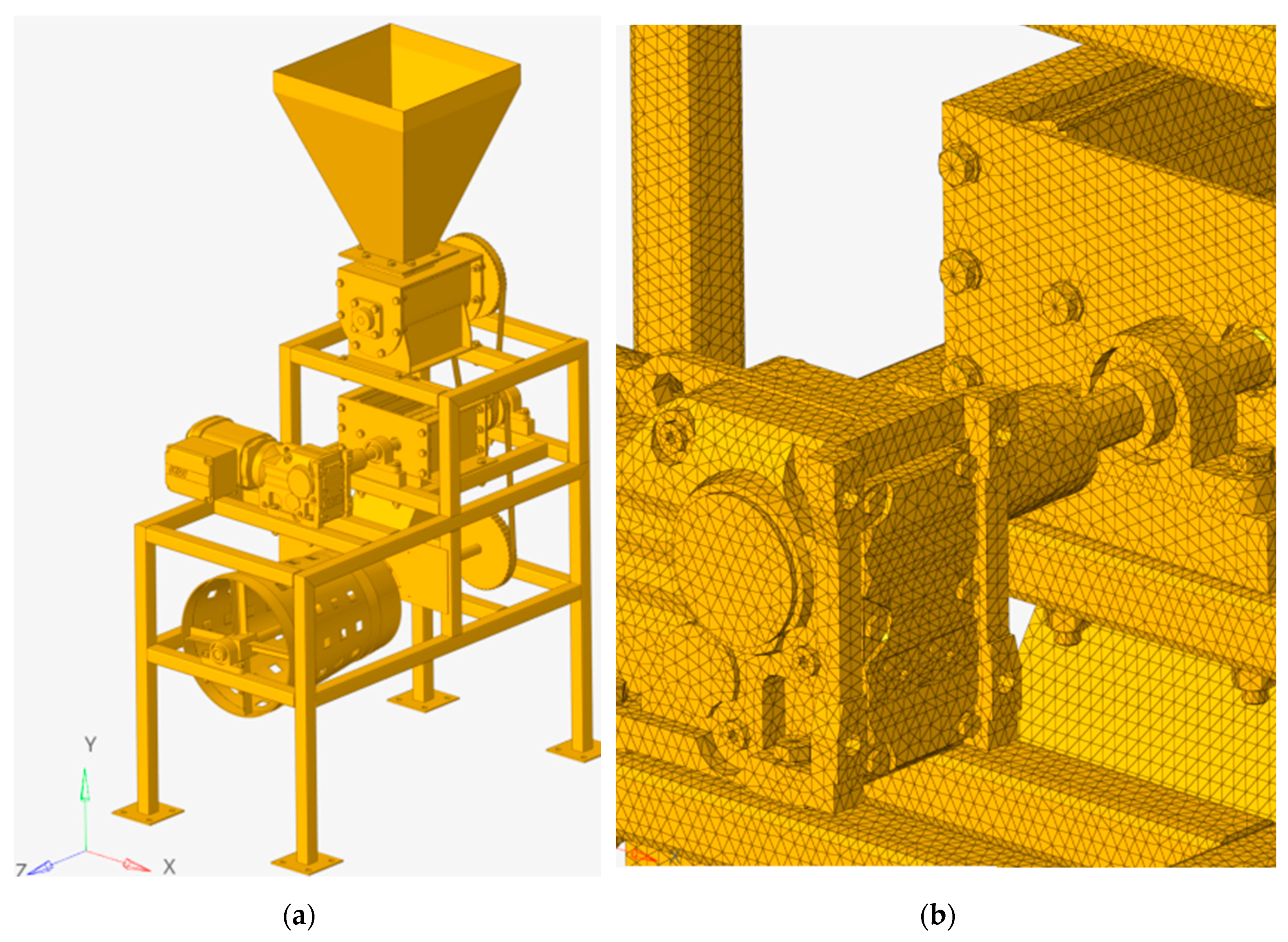
The subdivision of the geometry into discrete approximations, known as meshing, was automatically done by the software. In calculations that consider only stiffness, as is the case of the analysis of buckling modes and vibration modes, the influence of the mesh on the results is very small; thus, two different sizes were considered and the values obtained were equal or very similar, guaranteeing the mesh independence of the calculations. However, in stress analysis, a coarse mesh can yield inaccurate results; thus, it was necessary to carry out a mesh convergence study in order to achieve reliable results. The convergence method considered in static analysis was the adaptative method, through the iterative reduction of the mesh in the stress concentration zone until the difference between two consecutive iterations was affordable. The definitive mesh of the model (Figure 16a,b) was made up of 281,128 nodes and 864,095 elements. Solid second-order tetrahedrons were considered in the meshing calculation. Finally, the interaction between elements making up different parts of the machine was carried out through the kinematic conditions of the three relative degrees of freedom between the surfaces in contact (similar conditions to a welded connection); this assumption was valid because the loads were relatively small and the focus was on the parts to be connected. Additional conditions such as bolt prestress were not considered, further reinforcing this hypothesis.
In the part in contact with the fruit, A304 stainless-steel components were considered, in order to comply with the national hygiene and health regulations. For the other components, A500 steel (yielding strength = 250 MPa) for hollow structural sections was considered, and A36 steel profiles were considered for the sheet metal elements (yielding strength = 250 MPa), both easily found on the national market. The Young modulus of the materials considered was 200 GPa. The material properties used for modeling are listed in 
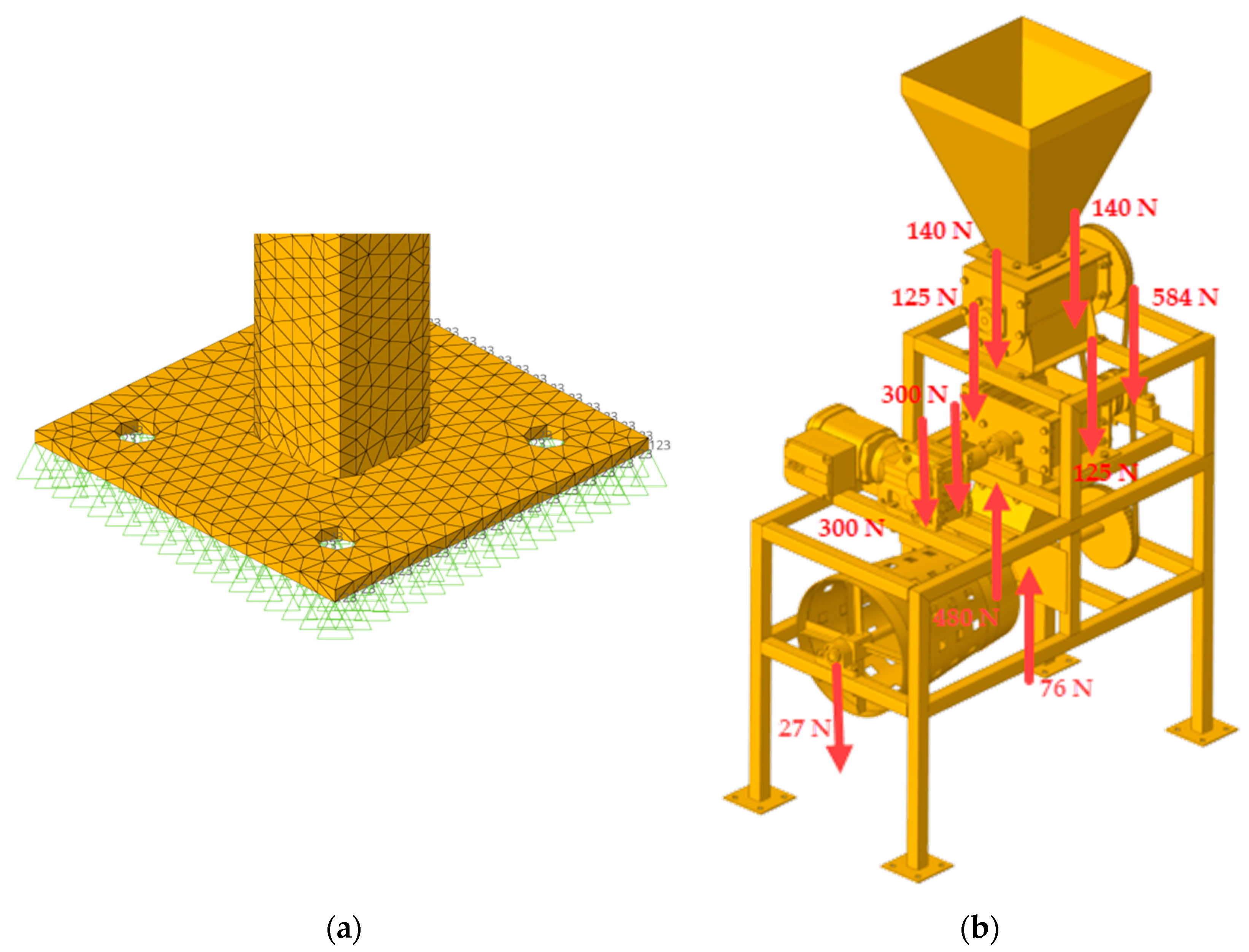
Table 4. Loads and boundary conditions correspond to the machine working, Figure 17a shows the boundary condition applied to each support and Figure 17b shows the loads applied to the structure by each component support.
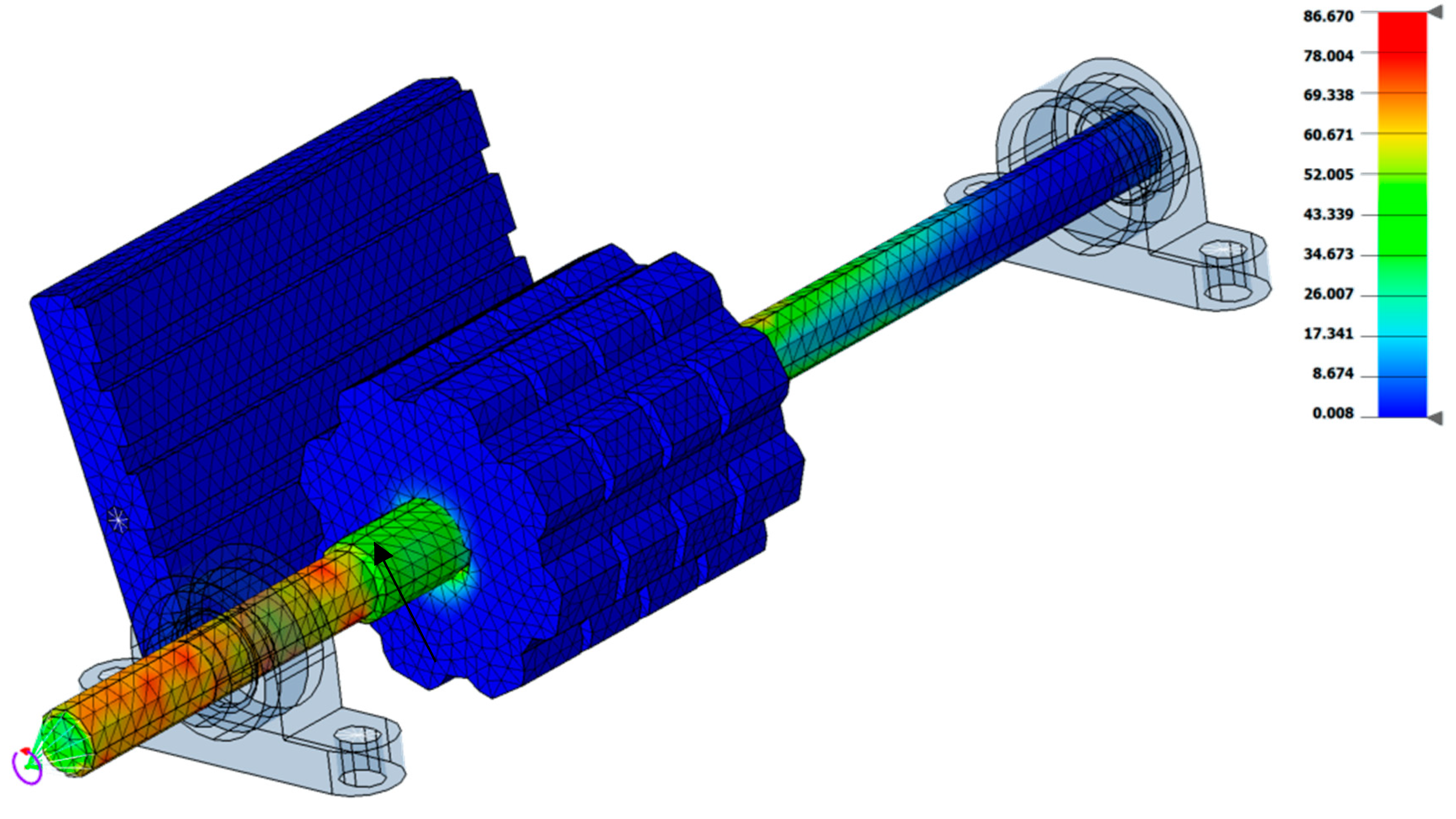
In addition to the analytic calculations of the machine structure, a static analysis corresponding to the worst condition of the components and structure of the machine was simulated. This condition was the blocking produced if the mechanism fracture could not crack the fruit or the stone inside. 
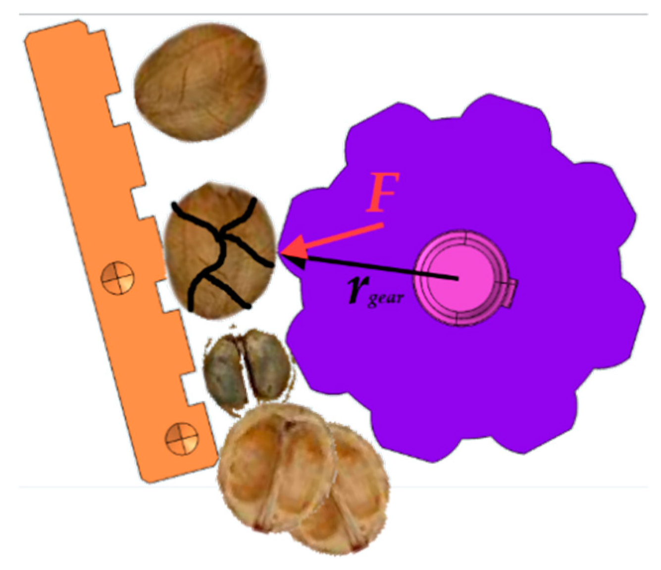
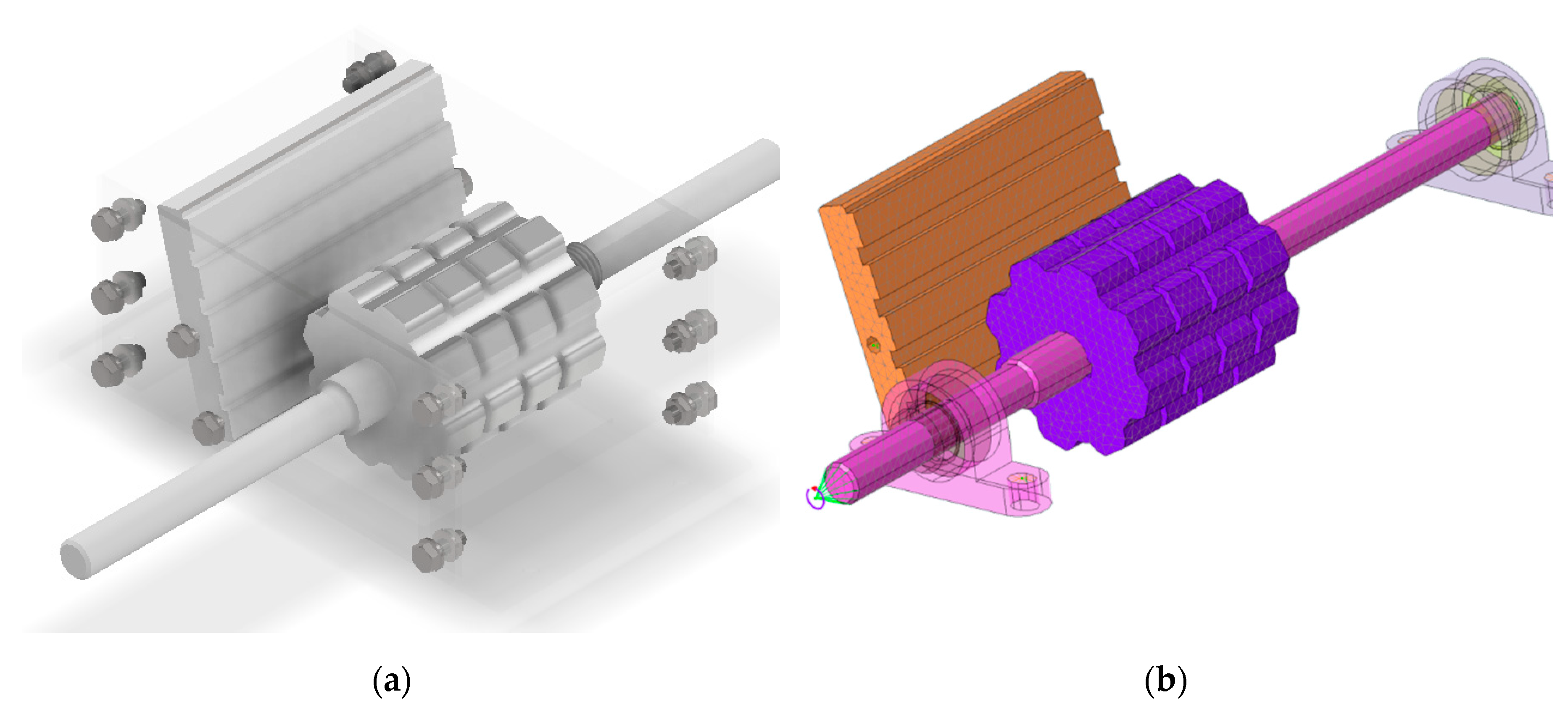
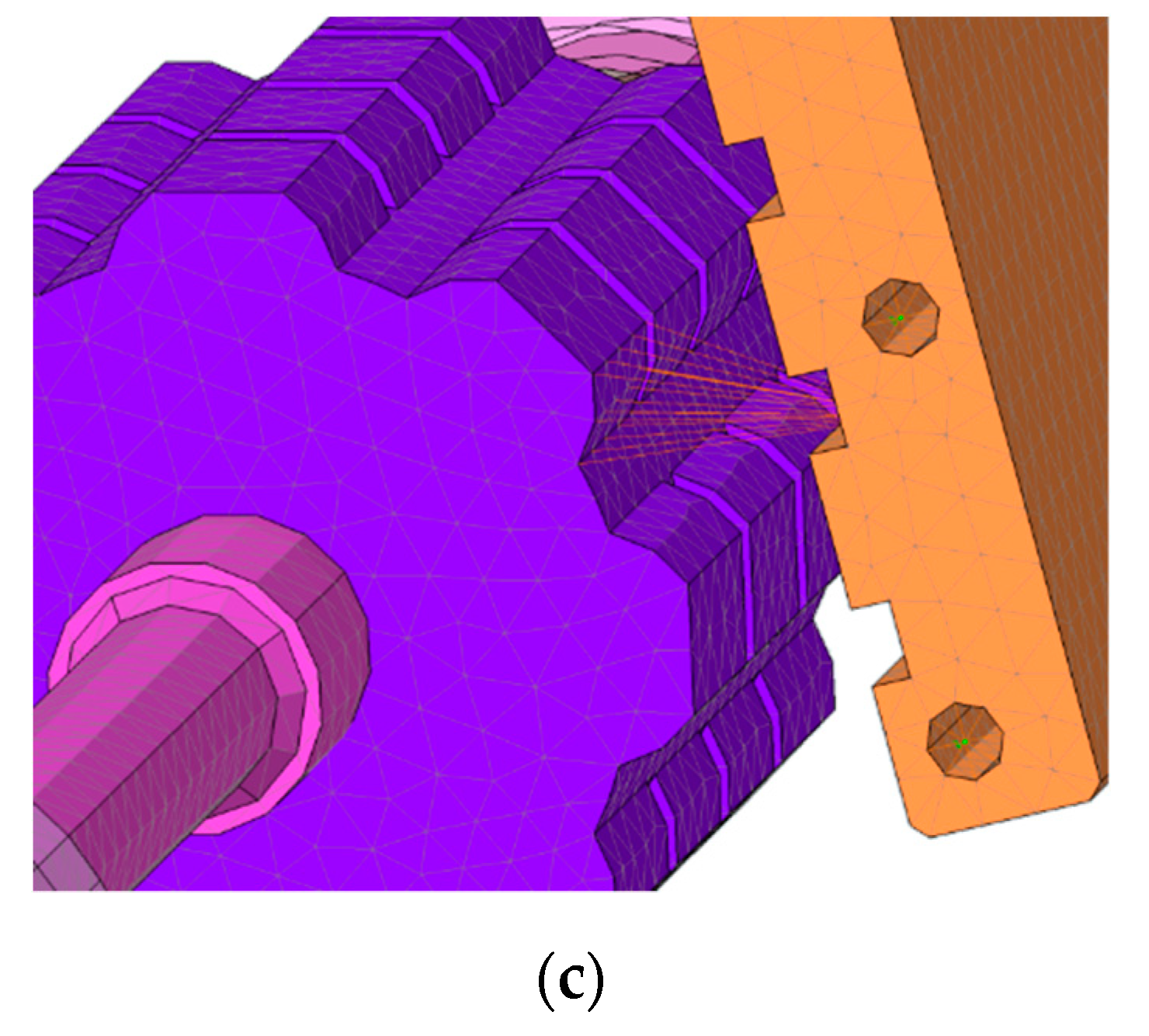
Figure 18a shows the fracture mechanism of the Metohuayo fruits analyzed, Figure 18b shows the mesh used, and Figure 18c is a detailed form of the mesh.
It was considered that this blocking would produce the maximum torque in the transmission, with a value of 2.4 corresponding to the nominal torque according to the electrical motor datasheet (144.8 Nm). Boundary conditions of the lateral supports corresponded to a sliding contact. All bolt connections were modeled as MPC (multipoint constraint) elements, which allowed connecting the nodes for which restrictions could be defined; hence, the behavior of these nodes was compatible with the boundary conditions established. Similarly, for the forced applied, a torque transmission proportional to the position of nodes in the outer surface was considered. The transmission from the toothed wheel to the Metohuayo cracking work plane was generated with RBE (rigid body elements).

3. Results and Discussion

3.1. Mechanical Behavior of the Metohuayo Fruit

According to the mechanical characterization of the Metohuayo fruit, a sample of 100 Metohuayo fruits were tested. Figure 19 shows the two main specimens from the sample, where each one represents the maximum and minimum strain measured along the test (6 and 13 mm, respectively). This also indicates the maximum force required to crack the Metohuayo shell, which is approximately 550 N. The strain information was used to establish the clearance needed in the fracture mechanism, while the maximum force allowed sizing the fracture mechanism components on the basis of materials theory, as well as calculating drive requirements such as torque and power.

3.2. Static Analysis

A static analysis of the whole structure and components was carried out in order to determine the magnitude of stresses along them and the critical zones where the stress was maximum. A first analysis was carried out with the machine in nominal operation conditions, and the results are shown in Figure 20a. The maximum stress calculated was 41.84 MPa, far from the yield strength of a conventional steel which is 250 MPa; hence, the minimum safety factor was 5.97. This value was high as expected due to the structural shapes dimensions used. It could be considered an oversizing; however, it corresponds to the fabrication requirements and material availability in local mechanic workshops in the rainforest from Perú. The structural shape selected is used as a standard there for different mechanical applications.
Additionally, it must be assured that the displacements do not affect the machine performance during its operation. In this sense, the displacement of each point along the machine and its structure was calculated, and the results are shown in Figure 20b. The maximum displacement was 0.4 mm and corresponded to the top of the chute, while there was practically no stress in this zone. This was due to the force locations, which were near the fracture mechanism at the first and second levels of the structure. There was a relatively large vertical distance between this zone, where the forces act, and the chute; hence, the displacements were amplified at the top.
A second static analysis was carried out according to the worst possible situation in the machine during its operation. This situation corresponded to the blocking of the fracture mechanism if Metohuayo fruits could not be cracked. When this situation occurred, the electric motor transmitted its maximum possible torque to the shaft and toothed wheel to crack the fruits. Obviously, in this situation, electronic components open the electrical circuit of the motor in order to avoid the very high current magnitude produced. The stress magnitudes produced during this condition are shown in Figure 21, where the maximum stress was 86.67 MPa and corresponded to the minor diameter section of the shaft, where torque and flection were superposed. This value was still far from the yield strength; hence, the machine would resist the blocking condition.

3.3. Buckling Analysis

In order to evaluate the reduction of the resistant capacity against compression stresses, a linear buckling analysis was performed. The results obtained in the buckling analysis correspond to the factor of the critical buckling load that destabilized the system. Therefore, a value greater than 1 refers to a security condition. Table 5 summarizes the safety factors associated with the main buckling modes defined in Figure 22. Due to the low load to which the system was subjected, the buckling factors were very high when not assuming a conditioning for its design and a risk for the integrity of the equipment.

3.4. Modal Analysis

Natural frequencies obtained analytically and using finite element method (FEM) are listed in Table 6. The first natural frequency calculated by the FEM model was very close to that calculated by the 1-DOF model. It must be known that an analytical model only focuses on vibration modes in which the designer is interested. Hence, only a 1-DOF model was considered to analyze the more flexible mode, corresponding to mode 1. FEM allowed determining more natural frequencies, and the analytical result allowed concluding that the FEM model was well developed.
As explained before, each natural frequency corresponds to a characteristic modal shape. Figure 23a,b shows the modal shape for the first and second natural frequencies. Their magnitudes were very similar as expected, explained by the similarity between the stiffness in these two horizontal directions. These modal shapes could be modeled as columns fixed to the ground and free on their ends according to the dynamic model presented in Figure 11. Equivalent mass was still the same for each horizontal direction, but the structure also practically maintained the same components, with no difference between bracings added in each direction. The deflection caused by an external force in each direction corresponded mainly to the large column of the structure which did not depend on the direction because it involved the same square tubes. If the tubes were not square, the section inertia would change and, thus, also the stiffness depending on the direction, but this was not the case.
Figure 23c shows the third vibration mode corresponding to the torsional vibration of the structure. Maximum displacement occurred on the chute and was higher than other displacements from the first and second mode. Figure 23d shows the fourth mode corresponding to the translation of each component mass; in contrast to the first and second mode, the fourth mode presents a more independent component mass vibration, where they did not move in the same direction.
It must be noted that each modal shape corresponded to free vibration. However, if an excitation frequency was sufficiently close to the corresponding natural frequency and the excitation force acted on the characteristic modal shape plane, the dynamical behavior would correspond to the vibration mode of this natural frequency. This condition must be avoided, as explained before. In this sense, it was verified that there were no excitation forces from components which could excite a modal shape; the values are listed in Table 7.
Finally, technical data of the automatic shell cracking machine developed are listed in Table 8, as a result of the analytical calculations and simulation.

4. Conclusions

A shell cracking machine of Metohuayo fruits was developed by applying VDI-2221 methodology. Conceptual solutions were proposed and evaluated in order to obtain an optimal design. Analytical analysis was carried out to determine dimensions, mechanical requirements from materials, and power consumption. In order to extend the analysis along the machine, CAD/CAE techniques and simulations were applied. The CAD and CAE tools used in this work demonstrate their applicability to this type of equipment.
Static analysis indicated a high safety factor in the structure as expected and could indicate an oversizing; however, it corresponded to the local requirements. The rainforest from Peru presents some particularities such as a corrosive environment and material availability. Local mechanic workshops only work with a few dimensions of structural shapes, including that selected for this machine as a standard. The worst operation conditions analyzed corresponded to a situation of fracture mechanism blocking, when the torque produced on the shaft increased to a maximum of 2.4 times its rated value. During this condition, it was found that each component of the machine and structure was able to resist with an acceptable safety factor, where the highest stress was 86.67 MPa, far from the yield strength of 250 MPa.
Modal analysis revealed that the excitation frequencies from the components were not able to excite one of the modes of vibration since the natural frequencies were far from the values. In the same way, displacements determined in static analysis were very small and, hence, there would be no amplitudes of vibration negatively affecting the dynamic performance of the machine.
The design methodology presented was customized to a special fruit processing, and the addition of a new mechanical characterization allowed assuring good performance of the machine for this particular application. This procedure and analysis could be applied for the development of multiple processing machines for particular fruits, especially from the rainforest, where various species continue being processed manually.
Finally, the results obtained from the analysis (safety factor related to static load of 670 against buckling, considering a long column) indicate that the machine designed was sturdy in its operation, including in the worst situation; thus, it is functional for small farmers’ requirements, as well as simple for fabrication with local technology.
As future research, an analysis of the dynamic behavior of Metohuayo fruits from feeding to separation could be carried out using the discrete element method (DEM). The interaction between their particles at each stage is very complex and, hence, requires experimentation and an appropriate statistical analysis of the data obtained.

Author Contributions

Conceptualization, J.J.J.d.C.F.; methodology, C.G.R.R., M.A.T.C. and J.J.J.d.C.F.; software, C.G.R.R., M.A.T.C. and J.J.J.d.C.F.; validation, C.G.R.R., M.A.T.C. and J.J.J.d.C.F.; formal analysis, C.G.R.R., M.A.T.C. and J.J.J.d.C.F.; writing—original draft preparation, C.G.R.R., M.A.T.C. and J.J.J.d.C.F.; writing—review and editing, C.G.R.R., M.A.T.C. and J.J.J.d.C.F. All authors have read and agreed to the published version of the manuscript.

Funding

This research received no external funding.

Acknowledgments

The authors would like to acknowledge CITE-Materiales PUCP for laboratory support.

Conflicts of Interest

The authors declare no conflict of interest.

References

  1. Ávila, L.M.; Merchán, J.A.D. Sondeo del Mercado Mundial de Inchi (Caryodendron orinocense). Available online: https://www.academia.edu/7205491/Sondeo_del_mercado_mundial_de_Inchi_Caryodendron_orinocense (accessed on 1 April 2019).
  2. Gonzáles, A.; Torres, G. Cultivo de Metohuayo. Available online: http://repositorio.iiap.org.pe/bitstream/IIAP/114/2/Gonzales_Libro_2010.pdf (accessed on 1 April 2019).
  3. Tratado de Cooperación Amazónica. Cultivo de Frutales Nativos Amazònicos: Manual del Extensionista. Available online: https://www.scribd.com/doc/18988919/Cultivo-de-Frutales-Nativos-Amazonicos (accessed on 1 April 2019).
  4. GBIF Backbone Taxonomy. Available online: https://doi.org/10.15468/39omei (accessed on 29 September 2020).
  5. Duke, J.A. Handbook of Nuts; CRC Press: Boca Raton, FL, USA, 2017; ISBN 9780203752685. [Google Scholar]
  6. Kahai Galería. Available online: https://www.kahai.co/nueces-kahai/ (accessed on 1 April 2019).
  7. Macadamia Nut Shelling Machine Automatically. Available online: https://www.youtube.com/watch?v=DGGPVuR8dD0&ab_channel=toantran (accessed on 30 March 2019).
  8. Maquina Peladora de Almendras. Available online: https://www.youtube.com/watch?v=xK0B5rZjwgI&ab_channel=AptMaquinas (accessed on 29 March 2019).
  9. Descapsuladora de Sacha Inchi. Available online: https://www.youtube.com/watch?v=I_FNs1BOpsI&ab_channel=MADECSAPERU (accessed on 29 March 2019).
  10. Verein Deutscher Ingenieure. VDI-Guideline 2221: Systematic Approach to the Development and Design of Technical Systems and Products; Verlag des Vereins Deutscher Ingenieure: Düsseldorf, Germany, 1993. [Google Scholar]
  11. Rojas, D. Diseño de una Máquina para Extraer Frutos de nuez de Macadamia con Capacidad de 100 kg/día. Engineer Bachelor’s Thesis, Pontificia Universidad Católica del Perú, Lima, Peru, 2017. [Google Scholar]
  12. Saravacos, G.; Kostaropoulos, A.E. Mechanical Processing Equipment; Springer: Berlin/Heidelberg, Germany, 2016; ISBN 9783319250182. [Google Scholar]
  13. Phal, G.; Beitz, W.; Feldhusen, J.; Grote, K.H. Engineering Design, 3rd ed.; Springer: Berlin/Heidelberg, Germany, 2007; ISBN 9788578110796. [Google Scholar]
  14. Bucklin, R.; Thompson, S.; Montross, M.; Abdel-Hadi, A. Grain Storage Systems Design; Elsevier Inc.: Amsterdam, The Netherlands, 2013; ISBN 9780123858825. [Google Scholar]
  15. Rao, S.S. Mechanical Vibrations; Pearson: London, UK, 2010; Volume 1, ISBN 9780132128193. [Google Scholar]
  16. Karlberg, M.; Löfstrand, M.; Sandberg, S.; Lundin, M. State of the art in simulation-driven design. Int. J. Prod. Dev. 2013, 18, 68–87. [Google Scholar] [CrossRef]
Figure 2. Metohuayo fruit processed by the machine.
Agriculture 10 00537 g002
Figure 3. Fruit compression test set-up.
Agriculture 10 00537 g003
Figure 4. Black box of the machine.
Agriculture 10 00537 g004
Figure 5. Optimal structure of functions.
Agriculture 10 00537 g005
Figure 6. Morphological table with functional elements: (a) chute; (b) chute with channels; (c) circular dosing unit; (d) screw conveyor; (e) toothed wheel with a curved toothed wall; (f) toothed wheel with a tilted toothed wall; (g) two toothed wheels; (h) vibrating screen; (i) rotating screen.
Agriculture 10 00537 g006
Figure 7. Three solution concepts according to the combination of functions presented in the morphological matrix; (a) a conceptual design based on toothed cylinder and wall mechanism; (b) based on toothed wheel and curved toothed wall mechanism; (c) based on two toothed cylinders.
Agriculture 10 00537 g007
Figure 8. Assessment diagram in accordance with VDI-2221 [10].
Agriculture 10 00537 g008
Figure 9. Final design: automatic shell cracking machine.
Agriculture 10 00537 g009
Figure 10. Fracture mechanism proposed.
Agriculture 10 00537 g010
Figure 11. (a) One degree of freedom (1-DOF) model of the machine; (b) frame model used to calculate the stiffness to the horizontal displacement from the equivalent mass.
Agriculture 10 00537 g011
Figure 12. Assembly plan of the shell cracking machine and its elements.
Agriculture 10 00537 g012
Figure 13. Assembly plan of the shell cracking machine and its elements: main views.
Agriculture 10 00537 g013
Figure 14. (a) Section of the shell cracking machine corresponds to the fruits flow; (b) Dosify and cracking of fruits section.
Agriculture 10 00537 g014
Figure 15. (a) Three-dimensional (3D) model considered in computer-aided engineering (CAE) analysis; (b) bearing support detail.
Agriculture 10 00537 g015
Figure 16. (a) Meshed shell craking machine model; (b) Mesh of the machine.
Agriculture 10 00537 g016
Figure 17. (a) Boundary conditions applied to each support; (b) loads applied to the structure.
Agriculture 10 00537 g017
Figure 18. (a) Fracture mechanism for Metohuayo fruits; (b) mesh of fracture mechanism; (c) detailed mesh of the toothed wheel and toothed wall.
Agriculture 10 00537 g018aAgriculture 10 00537 g018b
Figure 19. Compression force applied on the fruit’s shell (N) vs. strain produced (mm).
Agriculture 10 00537 g019
Figure 20. (a) Von Misses stresses contour (MPa) in static load case; (b) resultant displacements (mm) in static load case, scaled 500×.
Agriculture 10 00537 g020
Figure 21. Stress magnitudes (MPa) produced on the mechanism during a blocking condition.
Agriculture 10 00537 g021
Figure 22. Principal buckling modes shapes; (a) First; (b) Second; (c) Third and (d) Fourth buckling mode shape.
Agriculture 10 00537 g022aAgriculture 10 00537 g022b
Figure 23. Principal modal shapes of vibration; (a) First; (b) Second; (c) Third and (d) Fourth mode of vibration.
Agriculture 10 00537 g023
Table 1. Average dimensions measured from a sample of Metohuayo fruits.
DescriptionDimensions
Fruit length, width, and thickness33.5 mm, 35 mm, and 25 mm
Fruit weight18.9 g
Seed length, width, and thickness27.5 mm, 21.75 mm, and 16 mm
Seed weight12.6 g
Table 2. Technical assessment of the preliminary layouts.
Technical Value (xi)
Layouts123Ideal
NumberAssessment criteriagpgppgppgppgp
1Size224363648
2Design: stability, durability, wear3263939412
3Safety3393939412
4Fabrication236242448
5Assembly: feasibility224363648
6Maintenance3393926412
7Ergonomic design3263939412
xi 0.610.720.681.00
Table 3. Economical assessment of the preliminary layouts.
Economical Value (yi)
Layouts123Ideal
NumberAssessment criteriagpgppgppgppgp
1Power consumption3393926412
2Increasing capacity3263939412
3Operator training133333344
4Cost of spare parts3393926412
yi 0.6750.750.61
Table 4. Material properties.
SteelValueUnits
Elastic modulus200GPa
Poisson ratio0.3
Density7850kg/m3
Table 5. Critical load factors.
ModeFactor
1669.74
2775.92
3896.89
41158.04
Table 6. Natural frequencies of the system. FEM, finite element method.
Mode1-DOF ModelFEM
119.8 Hz21.22 Hz
2-23.54 Hz
3-40.35 Hz
4-47.72 Hz
Table 7. Excitation frequencies produced by components.
ComponentFrequency
Rotating Screen0.25 Hz
Screw Conveyor0.25 Hz
Fracture Mechanism0.5 Hz
Electric motor29.3 Hz
Table 8. Technical data of the machine developed.
ParameterValue
Capacity50 kg/h
Torque59 N·m
Rpm30
Power0.185 kW
Dimensions1080 mm × 60 mm × 1745 mm
Publisher’s Note: MDPI stays neutral with regard to jurisdictional claims in published maps and institutional affiliations.

