
Performance Analysis of DCMD Modules Enhanced with 3D-Printed Turbulence Promoters of Various Hydraulic Diameters


Abstract
1. Introduction
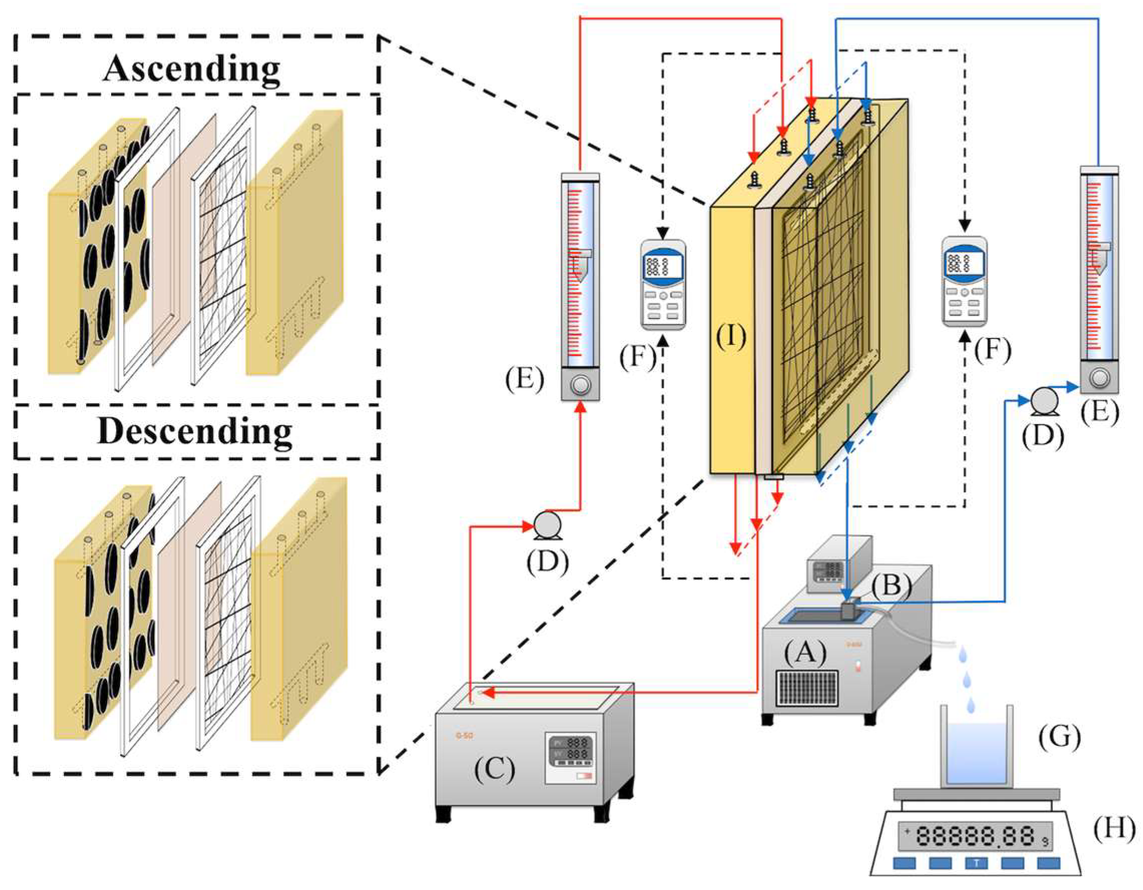
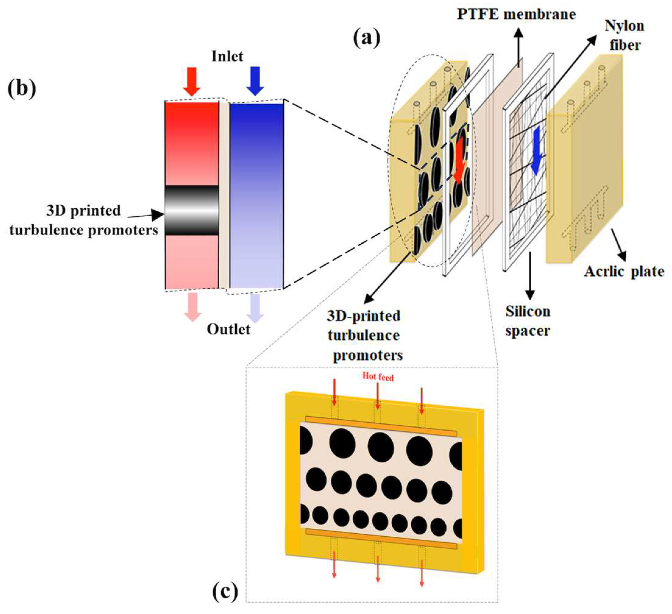
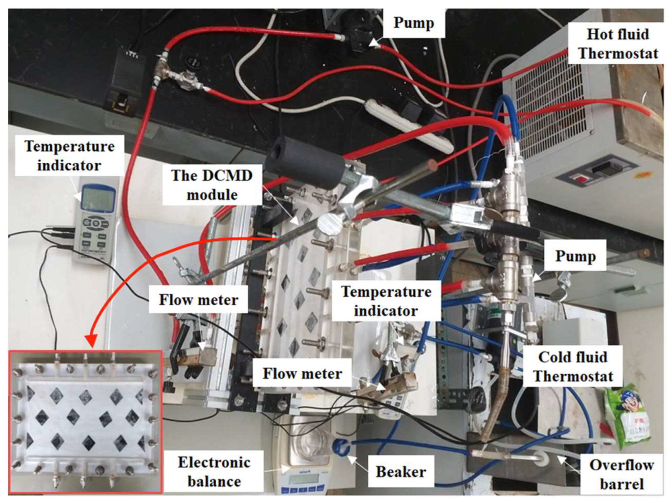
2. Experimental Apparatus and Materials
3. Theory and Analysis
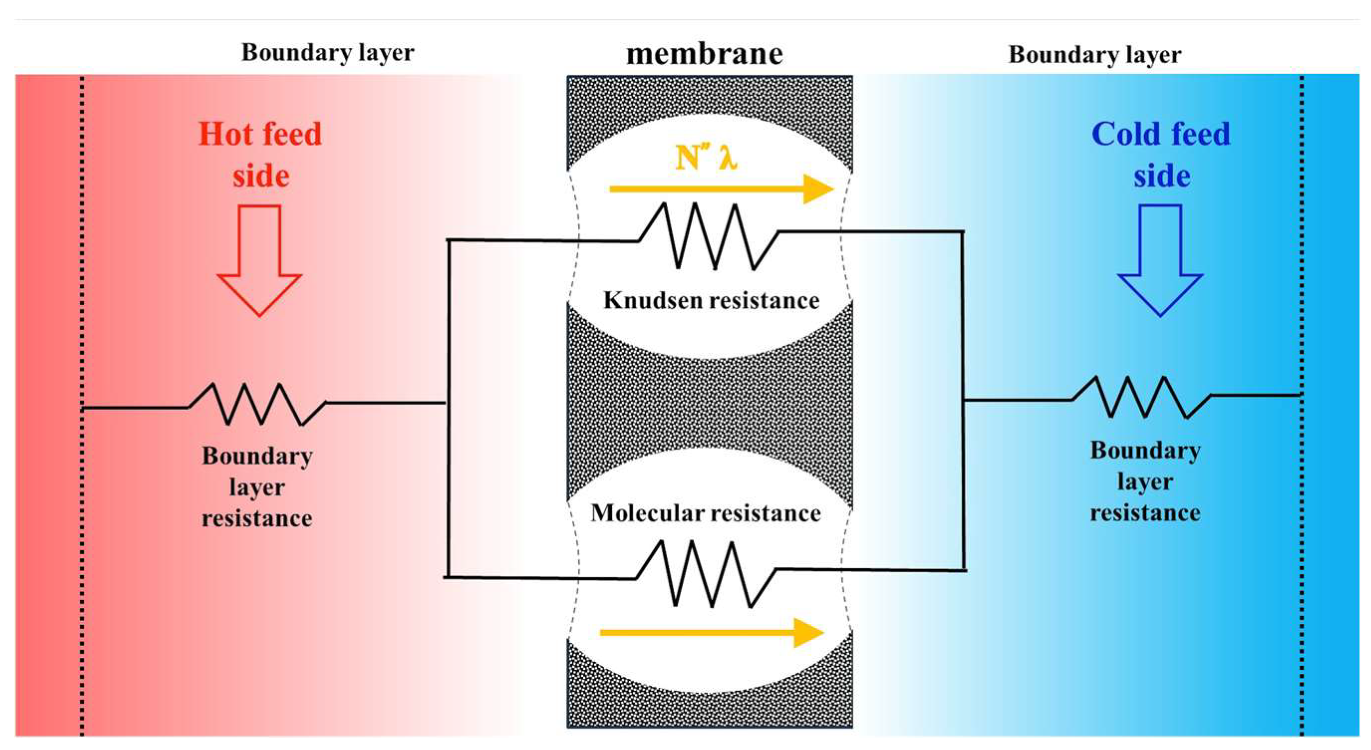
3.1. Mass Transfer
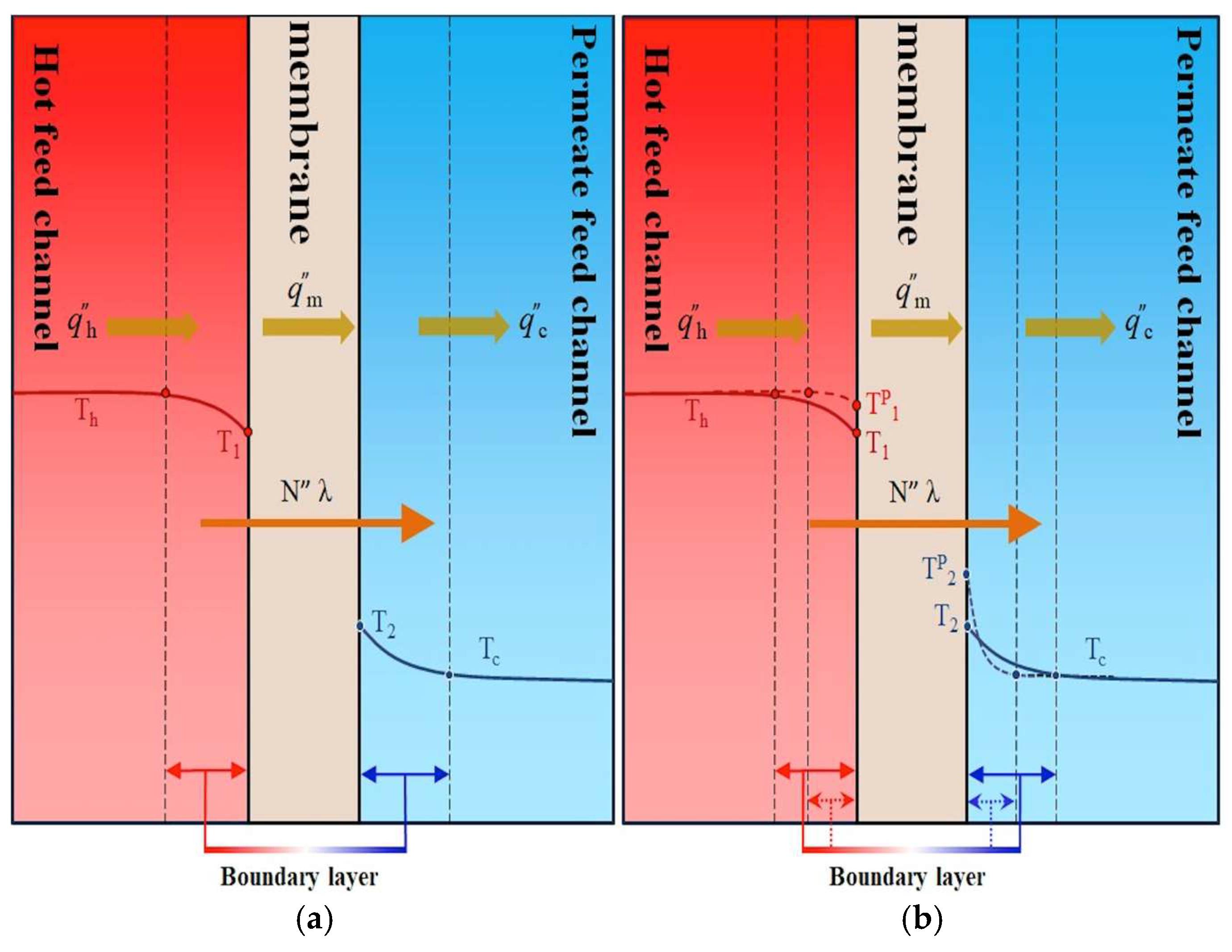
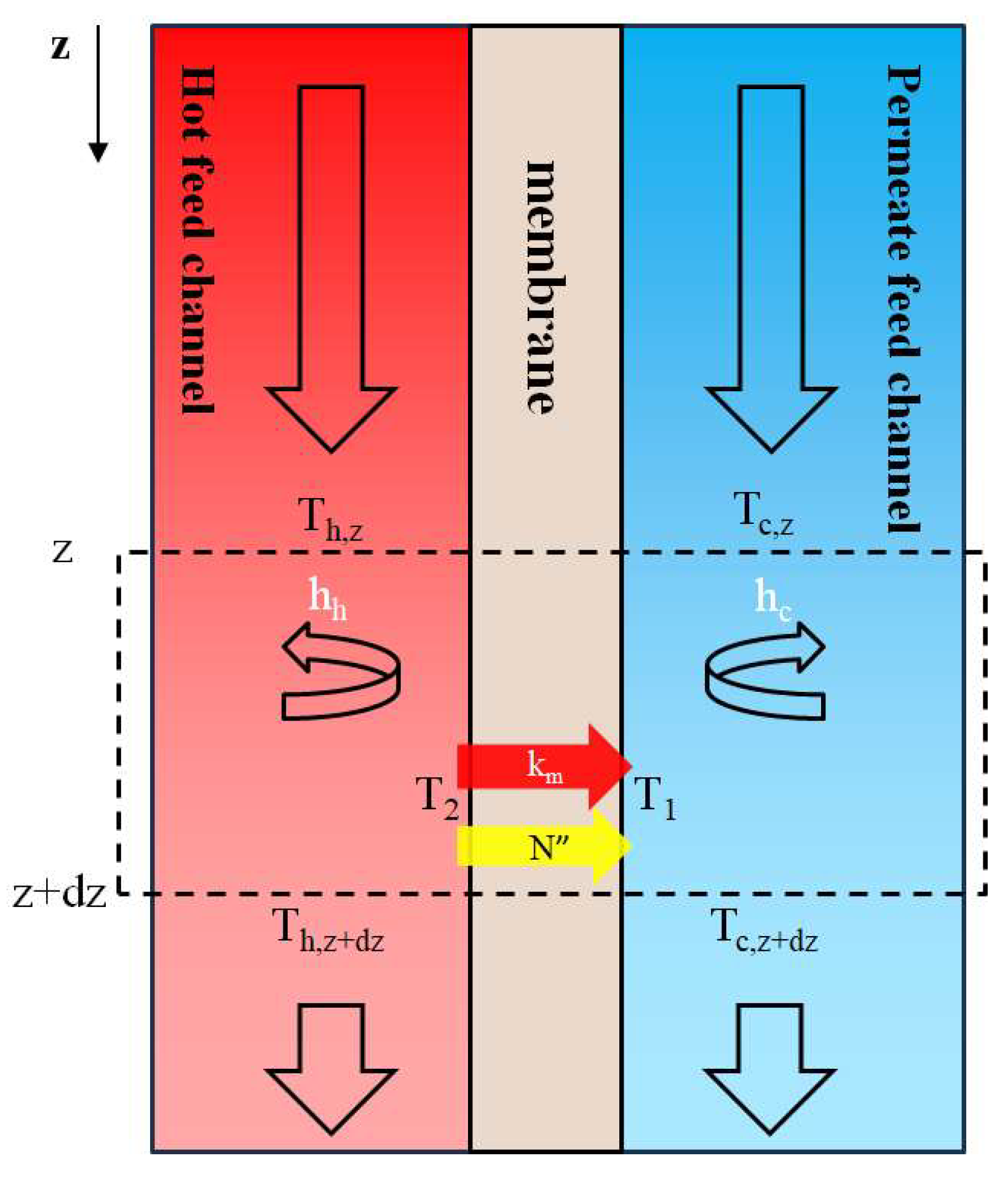
3.2. Heat Transfer
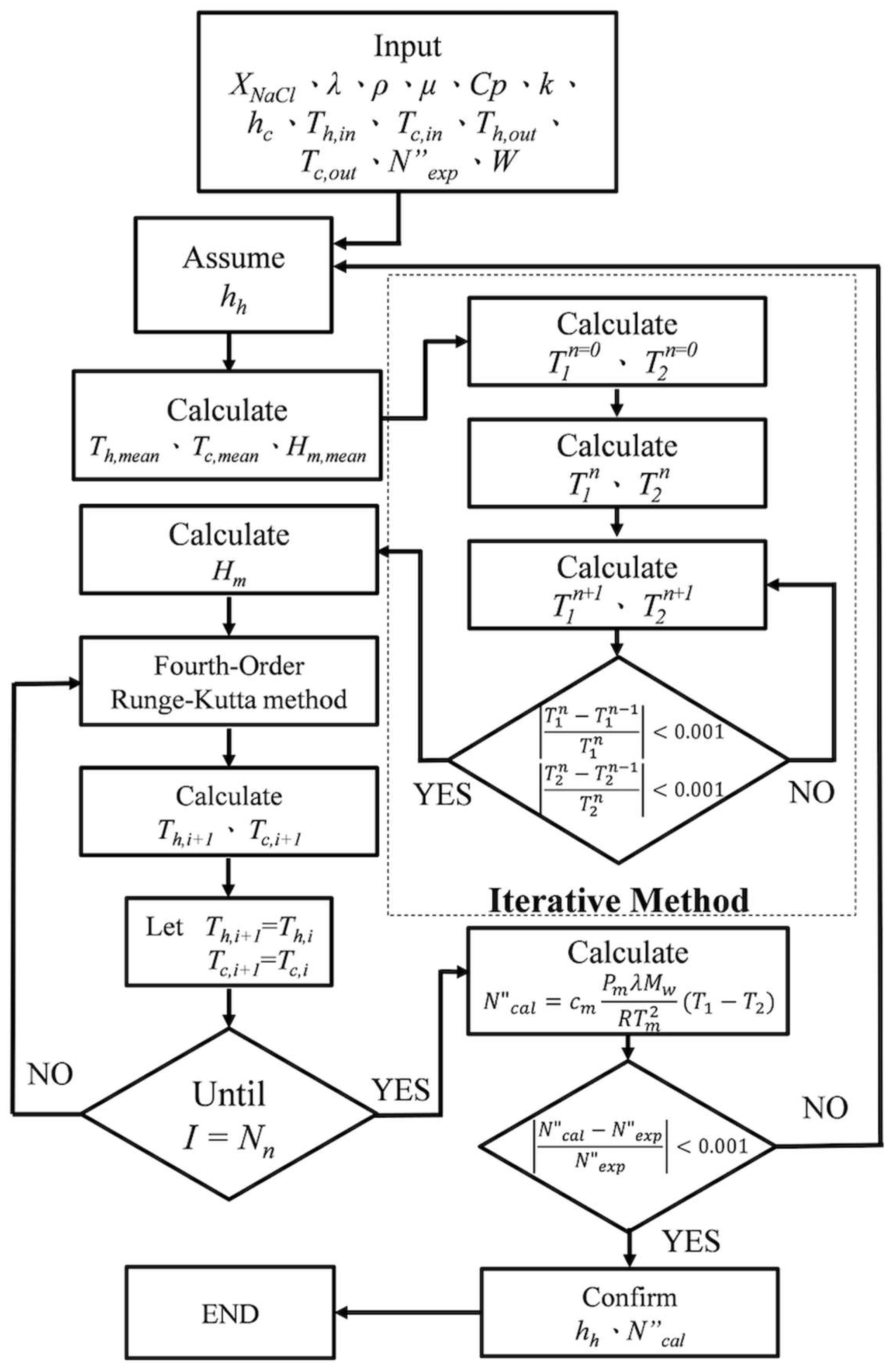
3.3. Theoretical Analyses of the Heat Transfer and Mass Transfer
3.4. Power Consumption Increment
4. Results and Discussions
4.1. Diminishing Temperature Polarization Effect by Inserting 3D-Printed Turbulence Promoters
4.2. Permeate Flux Improvement by Inserting 3D-Printed Turbulence Promoters
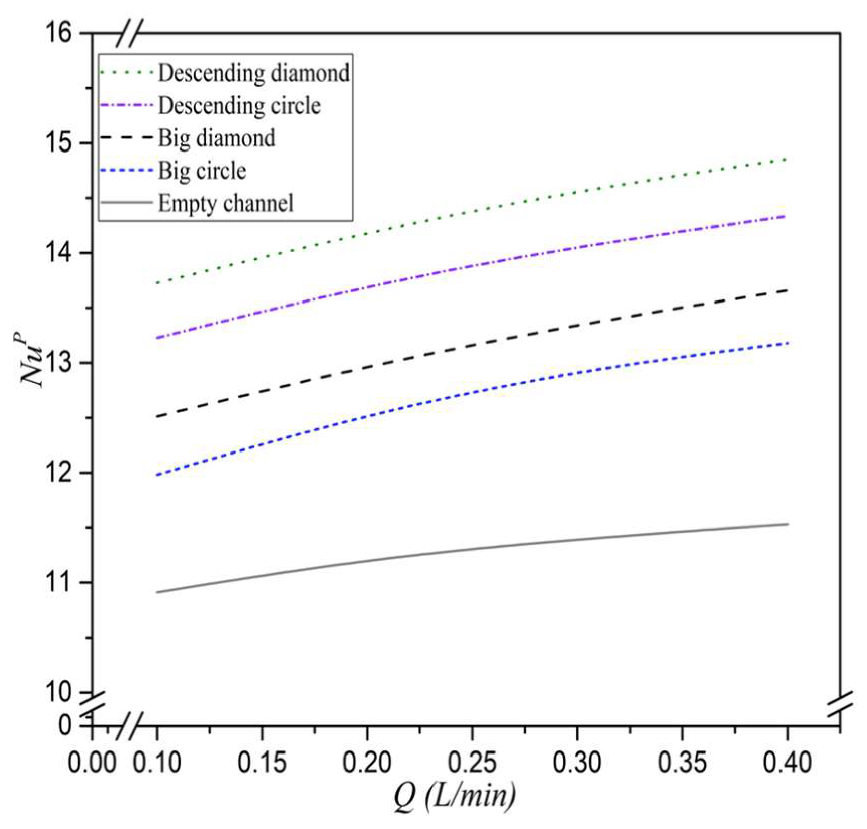
4.3. Heat Transfer Enhancement Factor
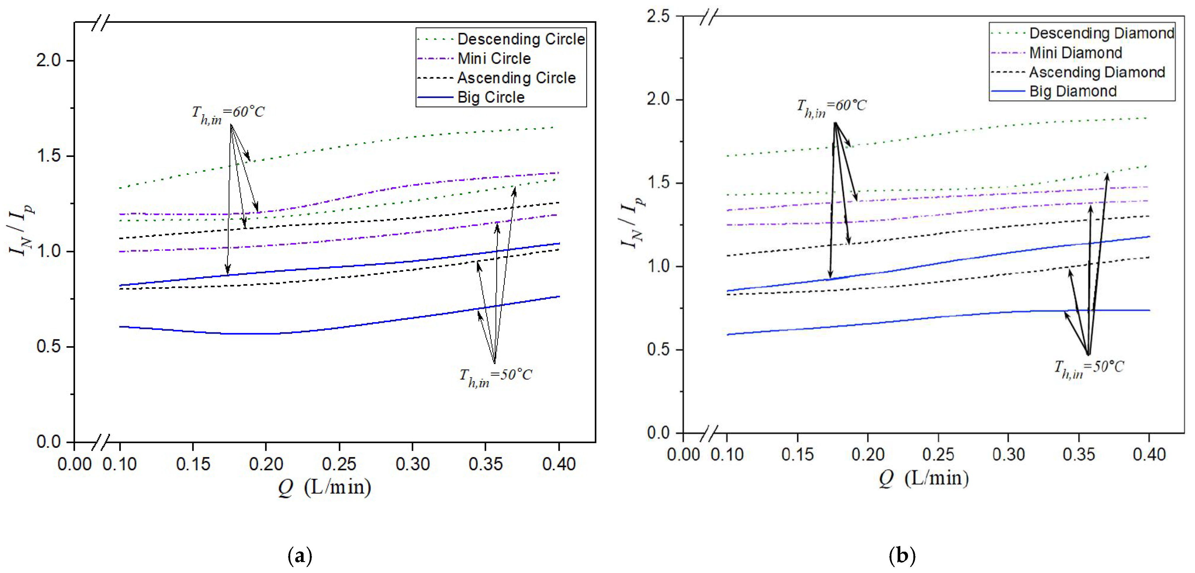
4.4. Energy Consumption Increment
5. Conclusions
- Implementing promoter-filled channels with descending hydraulic diameters in the hot saline feed stream resulted in a significant relative permeate flux improvement. A maximum enhancement of 91.73% was achieved at an inlet temperature of 60 °C and a flow rate of 0.4 L/min.
- Modules using uniform mini-type promoter-filled channels exhibited greater permeate flux improvements () compared to those using both ascending and descending promoter configurations. However, the ratio of , which normalizes performance by hydraulic effect, showed an inverse trend among different promoter types.
- Permeate flux improvements were more pronounced in modules with descending promoter-filled channels compared to ascending ones due to the development of a stronger and more uniform driving-force temperature gradient along the membrane module.
- Among various array configurations, descending promoter-filled channels showed a clearly positive effect on permeate flux. This is attributed to enhanced temperature gradients achieved by strategically varying the hydraulic diameters, thereby optimizing thermal boundary layer disruption.
Author Contributions
Funding
Institutional Review Board Statement
Data Availability Statement
Acknowledgments
Conflicts of Interest
Abbreviations
| Water activity in NaCl solution | |
| Available membrane surface area (m2) | |
| Friction losses coefficient | |
| Heat capacity () | |
| Membrane coefficient based on the Knudsen diffusion model () | |
| Membrane coefficient based on the molecular diffusion model () | |
| Membrane permeation coefficient () | |
| Turbulence promoter thickness (m) | |
| Diffusion coefficient of air and vapor in the membrane () | |
| Hydraulic equivalent diameter of channel (m), | |
| Accuracy deviation of experimental results from the theoretical predictions | |
| Fanning friction factor, | |
| Heat transfer coefficient of cold feed (W ) | |
| Heat transfer coefficient of hot saline feed (W ) | |
| Improved heat transfer coefficient of hot stream with promoter insertion (W ) | |
| Hydraulic dissipate energy (W), | |
| Permeate flux relative factor | |
| Power consumption relative index | |
| Thermal conductivity of water () | |
| Channel length (m) | |
| Friction loss (J kg−1), | |
| Molecular weight of water (kg mol−1) | |
| Average molecular weight of water and air (kg mol−1) | |
| The number of the flow segments under various configurations | |
| Permeate flux () | |
| Average value of for all numbers of experimental measurements () | |
| Number of experimental measurements | |
| Enhanced dimensionless Nusselt number | |
| Nusselt number for laminar flow | |
| Vapor pressure at membrane surface in the hot saline feed (Pa) | |
| Vapor pressure at membrane surface in the cold feed (Pa) | |
| Pressure at the temperature T (Pa) | |
| Mean saturated pressure in membrane (Pa) | |
| Saturation vapor pressure (Pa) | |
| Volumetric flow rate (m3 s−1) | |
| Heat flux () | |
| Membrane pore radius (m) | |
| Gas constant (8.314 J mol−1 K−1) | |
| Thermal resistance (K W−1) | |
| Reynolds number | |
| The ratio of the largest width of each promoter to the average big-circle promoter width | |
| Uncertainty of the experimental measurements | |
| Mean value of | |
| Membrane surface temperature in the hot saline feed region (K) | |
| Membrane surface temperature in the cold feed region (K) | |
| Membrane surface temperature with promoter insertion in the hot saline feed region (K) | |
| Membrane surface temperature with promoter insertion in the cold feed region (K) | |
| Average membrane temperature (K) | |
| Average velocity () | |
| Width of channel (m) | |
| Pseudo-average width occupied by turbulence promoters in each flow segment (m) | |
| Liquid mole fraction of water | |
| Mole fraction of NaCl in saline solution | |
| Vapor mole fraction of water | |
| Natural log mean vapor mole fraction of water in the membrane | |
| Axial coordinate along the flow direction (m) | |
| Greek letters | |
| Enhancement factor | |
| Thickness of membrane (µm) | |
| Membrane porosity | |
| Gas viscosity () | |
| Latent heat of water () | |
| Viscosity () | |
| Density () | |
| Diffusion volume of water () | |
| Diffusion volume of water () | |
| Membrane tortuosity | |
| Temperature polarization coefficients | |
| Subscripts | |
| 1 | Membrane surface on hot fluid side |
| Membrane surface on cold fluid side | |
| c | Cold feed stream |
| h | Hot feed stream |
| cor | Correlated results |
| empty | Channel without embedded turbulence promoters |
| exp | Experimental results |
| in | At the inlet |
| Laminar flow | |
| m | Membrane |
| out | At the outlet |
| promoter | Channel with embedded turbulence promoters |
| theo | Theoretical predictions |
| Superscripts | |
| h | Heat transfer mechanism |
| p | Promoter-filled channels |
References
- Tomaszewska, M. Membrane distillation-examples of applications in technology and environmental protection. Environ. Stud. 2005, 9, 27–36. [Google Scholar]
- Al-Obaidani, S.; Curcio, E.; Macedonio, F.; Profio, G.D.; Al-Hinai, H.; Drioli, E. Potential of membrane distillation in seawater desalination: Thermal efficiency, sensitivity study and cost estimation. J. Membr. Sci. 2008, 323, 85–98. [Google Scholar]
- Huang, Y.X.; Wang, Z.X.; Horseman, T.; Livingston, J.L.; Lin, S.H. Interpreting contact angles of surfactant solutions on microporous hydrophobic membranes. J. Membr. Sci. Let. 2022, 2, 100015–100019. [Google Scholar]
- Schofield, R.W.; Fane, A.G.; Fell, C.J.D. Heat and mass transfer in membrane distillation. J. Membr. Sci. 1987, 33, 299–313. [Google Scholar]
- Ichiyanagi, M.; Tsutsui, I.; Kakinuma, Y.; Sato, Y.; Hishida, K. Three-dimensional measurement of gas dissolution process in gas–liquid microchannel flow. Int. J. Heat Mass Transfer 2012, 55, 2872–2878. [Google Scholar]
- El-Bourawi, M.S.; Ding, Z.; Ma, R.; Khayet, M. A framework for better understanding membrane distillation separation process. J. Membr. Sci. 2006, 285, 4–29. [Google Scholar]
- Martínez-Díez, L.; Vázquez-González, M.I. Effects of polarization on mass transport through hydrophobic porous membranes. Ind. Eng. Chem. Res. 1998, 37, 4128–4135. [Google Scholar]
- Bandini, S.; Gostoli, C.; Sarti, G.C. Role of heat and mass transfer in membrane distillation process. Desalination 1991, 81, 91–106. [Google Scholar]
- Sheikh, M.; Chimeh, A.F.; Ashtiani, F.Z.; Fouladitajar, A.; Yavarzadeh, N. Mathematical Modeling of Direct Contact Membrane Distillation (DCMD) Using Knudsen-Diffusion Model for PVDF Membranes. J. Membr. Sci. Res. 2025, 11, 2040777. [Google Scholar]
- Suleman, M.; Asif, M.; Jamal, S.A. Temperature and concentration polarization in membrane distillation: A technical review. Desalination Water Treat. 2021, 229, 52–68. [Google Scholar]
- Yun, Y.; Ma, R.; Zhang, W.; Fane, A.G.; Li, J. Direct contact membrane distillation mechanism for high concentration NaCl solutions. Desalination 2006, 188, 251–262. [Google Scholar] [CrossRef]
- Ni, W.; Li, Y.; Zhang, G.; Du, X. Study of spacer structure on the enhancement of heat and mass transfer in direct contact membrane distillation modules. Desalination 2022, 530, 115617. [Google Scholar] [CrossRef]
- Alwatban, A.M.; Mohammed, M.A.; Aljumaily, M.M.; Alsalhy, Q.F. Computational fluid dynamics simulations of desalination processes in vacuum membrane distillation. Desalination Water Treat. 2025, 322, 101174. [Google Scholar] [CrossRef]
- Jeong, S.; Gu, B.; Choi, S.; Ahn, S.; Lee, J.; Jeong, S. Engineered multi-scale roughness of carbon nanofiller- embedded 3D printed spacers for membrane distillation. Water Res. 2023, 231, 119649. [Google Scholar] [CrossRef]
- Ho, C.D.; Chen, L.; Chen, L.; Huang, M.C.; Lai, J.Y.; Chen, Y.A. Distillate flux enhancement in the air gap membrane distillation with inserting carbon-fiber spacers. Sep. Sci. Technol. 2017, 52, 2815–2826. [Google Scholar] [CrossRef]
- Khalifa, A.; Ahmad, H.; Antar, M.; Laoui, T.; Khayet, M. Experimental and theoretical investigations on water desalination using direct contact membrane distillation. Desalination 2017, 404, 22–34. [Google Scholar] [CrossRef]
- Li, L.; Sirkar, K.K. Studies in vacuum membrane distillation with flat membranes. J. Membr. Sci. 2017, 523, 225–234. [Google Scholar] [CrossRef]
- Haidari, A.H.; Heijman, S.G.J.; van der Meer, W.G.J. Visualization of hydraulic conditions inside the feed channel of reverse osmosis: A practical comparison of velocity between empty and spacer–filled channel. Water Res. 2016, 106, 232–241. [Google Scholar] [CrossRef]
- Taamneh, Y.; Bataineh, K. Improving the performance of direct contact membrane distillation utilizing spacer-filled channel. Desalination 2017, 408, 25–35. [Google Scholar] [CrossRef]
- Dimitrov, D.; Schreve, K.; de Beer, N. Advances in three dimensional printing—State of the art and future perspectives. Rapid Prototyp. J. 2006, 12, 136–147. [Google Scholar] [CrossRef]
- Abueidda, D.W.; Dalaq, A.S.; Abu Al-Rub, R.K.; Younes, H.A. Finite element predictions of effective multifunctional properties of interpenetrating phase composites with novel triply periodic solid shell architectured reinforcements. Int. J. Mech. Sci. 2015, 92, 80–89. [Google Scholar] [CrossRef]
- Santos, J.L.C.; Geralds, V.; Velizarov, S.; Crespo, J.G. Investigation of flow patterns and mass transfer in membrane module channels filled with flow-aligned spacers using computational fluid dynamics (CFD). J. Membr. Sci. 2007, 305, 103–117. [Google Scholar] [CrossRef]
- Yeh, H.M. Effect of gradually varying baffled-ring distance on ultrafiltration in tubular membranes inserted concentrically with a ring rod. Desalination Water Treat. 2004, 40, 321–325. [Google Scholar] [CrossRef]
- Chang, H.; Ho, C.D.; Chen, Y.H.; Chen, L.; Hsu, T.H.; Lim, J.W.; Chiou, C.P.; Lin, P.H. Enhancing the permeate flux of direct contact membrane distillation modules with inserting 3D printing turbulence promoters. Membranes 2021, 11, 266. [Google Scholar] [CrossRef]
- Fukazawa, T.; Kawamura, H.; Tamura, T. Water vapour resistance of hydrophobic microporous membranes under reduced pressure at a constant temperature. J. Text. Inst. Part 1 1999, 4, 602–615. [Google Scholar] [CrossRef]
- Zhang, J.H.; Gary, H.; Li, J.D. Modeling heat and mass transfers in DCMD using compressible membranes. I. Knudsen-Poiseuille transition. J. Membr. Sci. 2012, 387–388, 7–16. [Google Scholar] [CrossRef]
- Ding, Z.W.; Ma, R.Y.; Fane, A.G. A new model for mass transfer in direct contact membrane distillation. Desalination 2003, 151, 217–227. [Google Scholar] [CrossRef]
- Iversen, S.B.; Bhatia, V.K.; Dam-Jphasen, K.; Jonsson, G. Characterization of microporous membranes for use in membrane contactors. J. Membr. Sci. 1997, 130, 19–27. [Google Scholar] [CrossRef]
- Fuller, E.N.; Schettler, P.D.; Giddings, J.C. Characterization of microporous membranes for use in membrane contactors. J. Membr. Sci. 1996, 58, 205–217. [Google Scholar]
- Lawson, K.W.; Lloyd, D.R. Membrane distillation. II. Direct contact MD. J. Membr. Sci. 1996, 120, 123–133. [Google Scholar] [CrossRef]
- Phattaranawik, J.; Jiraratananon, R.; Fane, A.G. Effects of net-type spacers on heat and mass transfer in direct contact membrane distillation and comparison with ultrafiltration studies. J. Membr. Sci. 2003, 217, 193–206. [Google Scholar] [CrossRef]
- Phattaranawik, J.; Jiraratananon, R.; Fane, G.A. Effect of pore size distribution and air flux on mass transport in direct contact membrane distillation. J. Membr. Sci. 2003, 215, 75–85. [Google Scholar] [CrossRef]
- Kern, D.Q. Process Heat Transfer; McGraw-Hill: New York, NY, USA, 1950. [Google Scholar]
- Welty, J.R.; Wick, C.E.; Wilson, R.E. Fundamentals of Momentum, Heat, and Mass Transfer, 3rd ed.; John Wiley & Sons: New York, NY, USA, 1984. [Google Scholar]
- Kakac, S.; Shah, R.K.; Aung, W. Handbook of Single-Phase Convective Heat Transfer; Wiley: New York, NY, USA, 1987. [Google Scholar]
- Moffat, R.J. Describing the uncertainties in experimental results. Exp. Thermal Fluid Sci. 1988, 1, 3–17. [Google Scholar] [CrossRef]


| Array Configurations | (mm) | ||
|---|---|---|---|
| Big circle | 4 | 9.76 | 1.57 |
| Medium circle | 6 | 6.51 | 1.28 |
| Mini circle | 8 | 4.88 | 1.11 |
| Ascending circle | 8 | 4.88 | 1.43 |
| Descending circle | 4 | 9.76 | 1.43 |
| Big diamond | 4 | 9.77 | 1.80 |
| Medium diamond | 6 | 6.52 | 1.47 |
| Mini diamond | 8 | 4.89 | 1.28 |
| Ascending diamond | 8 | 4.89 | 1.64 |
| Descending diamond | 4 | 9.77 | 1.64 |
) | (L/min) | Promoter-Filled Channel Configurations with Descending Hydraulic Diameter | |||||
|---|---|---|---|---|---|---|---|
| Circle-Type | Diamond-Type | ||||||
(kg m−2 h−1) | (kg m−2 h−1) | (kg m−2 h−1) | (kg m−2 h−1) | ||||
| 45 | 0.1 | 1.98 | 2.08 | 5.43 | 2.21 | 2.09 | 5.05 |
| 0.2 | 2.49 | 2.47 | 3.72 | 2.42 | 2.51 | 0.80 | |
| 0.3 | 2.75 | 2.67 | 6.78 | 2.95 | 2.75 | 2.91 | |
| 0.4 | 3.21 | 3.02 | 8.31 | 3.37 | 3.09 | 5.92 | |
| 50 | 0.1 | 2.74 | 2.82 | 3.09 | 2.91 | 2.82 | 2.92 |
| 0.2 | 3.52 | 3.45 | 3.51 | 3.42 | 3.54 | 1.99 | |
| 0.3 | 3.87 | 3.97 | 1.21 | 4.12 | 4.07 | 2.58 | |
| 0.4 | 4.13 | 4.23 | 3.34 | 4.49 | 4.34 | 2.42 | |
| 55 | 0.1 | 3.27 | 3.38 | 1.17 | 3.42 | 3.46 | 3.36 |
| 0.2 | 4.21 | 4.19 | 2.27 | 4.41 | 4.31 | 0.48 | |
| 0.3 | 5.05 | 4.86 | 3.62 | 5.25 | 5.06 | 3.76 | |
| 0.4 | 5.74 | 5.41 | 8.01 | 6.12 | 5.63 | 5.75 | |
| 60 | 0.1 | 4.32 | 4.62 | 0.81 | 4.91 | 4.87 | 6.94 |
| 0.2 | 5.13 | 5.28 | 4.45 | 5.84 | 5.58 | 2.92 | |
| 0.3 | 6.26 | 6.05 | 0.31 | 6.54 | 6.56 | 3.35 | |
| 0.4 | 6.56 | 6.28 | 5.88 | 6.46 | 6.84 | 4.27 | |
) | (L/min) | Promoter-Filled Channel Configurations with Uniform Big-Type Promoters | ||||
|---|---|---|---|---|---|---|
| Empty Channel | Circle-Type | Diamond-Type | ||||
(kg m−2 h−1) | (kg m−2 h−1) | (%) | (kg m−2 h−1) | |||
| 45 | 0.1 | 1.29 | 1.59 | 23.25 | 1.70 | 31.78 |
| 0.2 | 1.58 | 1.93 | 22.15 | 2.05 | 29.74 | |
| 0.3 | 1.76 | 2.11 | 19.88 | 2.26 | 28.40 | |
| 0.4 | 2.04 | 2.40 | 17.64 | 2.57 | 25.98 | |
| 50 | 0.1 | 1.63 | 2.11 | 29.44 | 2.24 | 37.42 |
| 0.2 | 2.11 | 2.67 | 26.54 | 2.82 | 33.64 | |
| 0.3 | 2.47 | 3.11 | 25.91 | 3.26 | 31.98 | |
| 0.4 | 2.67 | 3.33 | 24.71 | 3.49 | 30.71 | |
| 55 | 0.1 | 1.88 | 2.51 | 33.51 | 2.74 | 45.74 |
| 0.2 | 2.43 | 3.22 | 32.51 | 3.42 | 40.74 | |
| 0.3 | 2.91 | 3.78 | 29.89 | 4.02 | 38.14 | |
| 0.4 | 3.32 | 4.23 | 27.40 | 4.48 | 34.93 | |
| 60 | 0.1 | 2.54 | 3.41 | 34.25 | 3.78 | 48.81 |
| 0.2 | 2.94 | 3.94 | 34.01 | 4.34 | 47.61 | |
| 0.3 | 3.49 | 4.65 | 33.23 | 5.12 | 46.70 | |
| 0.4 | 3.67 | 4.88 | 32.97 | 5.34 | 45.50 | |
) | (L/min) | Promoter-Filled Channel Configurations with Uniform Mini-Type Promoters | ||||
|---|---|---|---|---|---|---|
| Empty Channel | Circle-Type | Diamond-Type | ||||
(kg m−2 h−1) | (kg m−2 h−1) | (%) | (kg m−2 h−1) | |||
| 45 | 0.1 | 1.29 | 2.23 | 72.86 | 2.44 | 89.14 |
| 0.2 | 1.58 | 2.57 | 62.66 | 2.88 | 82.27 | |
| 0.3 | 1.76 | 2.81 | 59.65 | 3.19 | 81.25 | |
| 0.4 | 2.04 | 3.24 | 58.82 | 3.68 | 80.39 | |
| 50 | 0.1 | 1.63 | 2.89 | 77.30 | 3.16 | 93.86 |
| 0.2 | 2.11 | 3.52 | 66.82 | 3.94 | 86.72 | |
| 0.3 | 2.47 | 4.02 | 62.75 | 4.57 | 85.02 | |
| 0.4 | 2.67 | 4.23 | 58.42 | 4.91 | 83.89 | |
| 55 | 0.1 | 1.88 | 3.37 | 79.25 | 3.62 | 92.55 |
| 0.2 | 2.43 | 4.21 | 73.25 | 4.66 | 91.76 | |
| 0.3 | 2.91 | 4.86 | 67.01 | 5.53 | 90.03 | |
| 0.4 | 3.32 | 5.39 | 62.34 | 6.23 | 87.65 | |
| 60 | 0.1 | 2.54 | 4.63 | 82.28 | 4.92 | 93.70 |
| 0.2 | 2.94 | 5.31 | 80.61 | 5.67 | 92.85 | |
| 0.3 | 3.49 | 6.27 | 79.65 | 6.59 | 88.82 | |
| 0.4 | 3.67 | 6.52 | 77.65 | 6.89 | 87.73 | |
) | (L/min) | Promoter-Filled Channel Configurations with Descending Hydraulic Diameters | ||||
|---|---|---|---|---|---|---|
| Empty Channel | Circle-Type | Diamond-Type | ||||
(kg m−2 h−1) | (kg m−2 h−1) | (%) | (kg m−2 h−1) | |||
| 45 | 0.1 | 1.29 | 2.08 | 61.24 | 2.09 | 62.02 |
| 0.2 | 1.58 | 2.47 | 56.32 | 2.51 | 58.86 | |
| 0.3 | 1.76 | 2.67 | 51.70 | 2.75 | 56.25 | |
| 0.4 | 2.04 | 3.02 | 48.03 | 3.09 | 51.47 | |
| 50 | 0.1 | 1.63 | 2.82 | 73.01 | 2.82 | 73.01 |
| 0.2 | 2.11 | 3.45 | 63.50 | 3.54 | 67.77 | |
| 0.3 | 2.47 | 3.97 | 60.72 | 4.07 | 64.77 | |
| 0.4 | 2.67 | 4.23 | 58.42 | 4.34 | 62.54 | |
| 55 | 0.1 | 1.88 | 3.38 | 79.78 | 3.46 | 84.04 |
| 0.2 | 2.43 | 4.19 | 72.42 | 4.31 | 77.36 | |
| 0.3 | 2.91 | 4.86 | 67.01 | 5.06 | 73.88 | |
| 0.4 | 3.32 | 5.41 | 62.95 | 5.63 | 69.57 | |
| 60 | 0.1 | 2.54 | 4.62 | 81.88 | 4.87 | 91.73 |
| 0.2 | 2.94 | 5.28 | 79.59 | 5.58 | 89.79 | |
| 0.3 | 3.49 | 6.05 | 73.35 | 6.56 | 87.96 | |
| 0.4 | 3.67 | 6.28 | 71.11 | 6.84 | 86.37 | |
) | (L/min) | Promoter-Filled Channel Configurations with Ascending Hydraulic Diameters | ||||
|---|---|---|---|---|---|---|
| Empty Channel | Circle-Type | Diamond-Type | ||||
(kg m−2 h−1) | (kg m−2 h−1) | (%) | (kg m−2 h−1) | |||
| 45 | 0.1 | 1.29 | 1.78 | 37.98 | 1.84 | 42.63 |
| 0.2 | 1.58 | 2.16 | 36.71 | 2.23 | 41.13 | |
| 0.3 | 1.76 | 2.35 | 33.52 | 2.46 | 39.77 | |
| 0.4 | 2.04 | 2.71 | 32.84 | 2.83 | 38.72 | |
| 50 | 0.1 | 1.63 | 2.32 | 42.33 | 2.35 | 44.17 |
| 0.2 | 2.11 | 2.99 | 41.71 | 3.03 | 43.60 | |
| 0.3 | 2.47 | 3.41 | 38.05 | 3.51 | 42.10 | |
| 0.4 | 2.67 | 3.64 | 36.32 | 3.74 | 40.07 | |
| 55 | 0.1 | 1.88 | 2.73 | 45.21 | 2.94 | 56.38 |
| 0.2 | 2.43 | 3.49 | 43.62 | 3.76 | 54.73 | |
| 0.3 | 2.91 | 4.15 | 42.61 | 4.41 | 51.54 | |
| 0.4 | 3.32 | 4.67 | 40.66 | 4.85 | 46.08 | |
| 60 | 0.1 | 2.54 | 3.85 | 51.57 | 4.05 | 59.44 |
| 0.2 | 2.94 | 4.43 | 50.68 | 4.65 | 58.16 | |
| 0.3 | 3.49 | 5.15 | 47.56 | 5.51 | 57.87 | |
| 0.4 | 3.67 | 5.34 | 45.50 | 5.74 | 56.40 | |
() | (L/min) | Descending Promoter-Filled Channels | |||||
|---|---|---|---|---|---|---|---|
| Big-Circle | Big-Diamond | Descending Circle-Type | Descending Diamond-Type | ||||
| (%) | (%) | (%) | (%) | (%) | |||
| 45 | 0.1 | 23.25 | 31.78 | 61.24 | 22.94 | 62.02 | 30.81 |
| 0.2 | 22.15 | 29.74 | 56.32 | 22.43 | 58.86 | 27.97 | |
| 0.3 | 19.88 | 28.40 | 51.70 | 21.68 | 56.25 | 26.54 | |
| 0.4 | 17.64 | 25.98 | 48.03 | 20.23 | 51.47 | 25.83 | |
| 50 | 0.1 | 29.44 | 37.42 | 73.01 | 25.89 | 73.01 | 33.64 |
| 0.2 | 26.54 | 33.64 | 63.50 | 25.53 | 67.77 | 29.21 | |
| 0.3 | 25.91 | 31.98 | 60.72 | 24.84 | 64.77 | 27.65 | |
| 0.4 | 24.71 | 30.71 | 58.42 | 24.35 | 62.54 | 27.02 | |
| 55 | 0.1 | 33.51 | 45.74 | 79.78 | 26.27 | 84.04 | 34.66 |
| 0.2 | 32.51 | 40.74 | 72.42 | 26.023 | 77.36 | 30.12 | |
| 0.3 | 29.89 | 38.14 | 67.01 | 25.87 | 73.88 | 28.57 | |
| 0.4 | 27.40 | 34.93 | 62.95 | 25.66 | 69.57 | 27.89 | |
| 60 | 0.1 | 34.25 | 48.81 | 81.88 | 28.83 | 91.73 | 35.48 |
| 0.2 | 34.01 | 47.61 | 79.59 | 28.57 | 89.79 | 34.01 | |
| 0.3 | 33.23 | 46.70 | 73.35 | 28.12 | 87.96 | 30.10 | |
| 0.4 | 32.97 | 45.50 | 71.11 | 28.08 | 86.37 | 28.68 | |
| ) | (L/min) | Thermal Resistances (or Convection Resistance) (K/W) | ||||||
|---|---|---|---|---|---|---|---|---|
| Circle-Type | Diamond-Type | |||||||
| Empty Channel | Big | Descending | Mini | Big | Descending | Mini | ||
| 45 | 0.1 | 3.64 | 2.90 | 2.65 | 2.48 | 2.76 | 2.36 | 2.35 |
| 0.2 | 3.56 | 2.81 | 2.58 | 2.41 | 2.68 | 2.30 | 2.28 | |
| 0.3 | 3.49 | 2.73 | 2.51 | 2.35 | 2.60 | 2.24 | 2.22 | |
| 0.4 | 3.42 | 2.65 | 2.45 | 2.30 | 2.53 | 2.19 | 2.17 | |
| 50 | 0.1 | 3.53 | 2.75 | 2.55 | 2.38 | 2.62 | 2.27 | 2.25 |
| 0.2 | 3.45 | 2.67 | 2.48 | 2.33 | 2.54 | 2.21 | 2.19 | |
| 0.3 | 3.38 | 2.60 | 2.41 | 2.27 | 2.47 | 2.16 | 2.14 | |
| 0.4 | 3.31 | 2.53 | 2.35 | 2.22 | 2.41 | 2.11 | 2.09 | |
| 55 | 0.1 | 3.42 | 2.58 | 2.45 | 2.30 | 2.46 | 2.19 | 2.17 |
| 0.2 | 3.35 | 2.51 | 2.38 | 2.24 | 2.39 | 2.13 | 2.11 | |
| 0.3 | 3.28 | 2.45 | 2.33 | 2.19 | 2.33 | 2.09 | 2.06 | |
| 0.4 | 3.21 | 2.38 | 2.27 | 2.14 | 2.27 | 2.04 | 2.01 | |
| 60 | 0.1 | 3.31 | 2.49 | 2.35 | 2.22 | 2.38 | 2.11 | 2.09 |
| 0.2 | 3.25 | 2.45 | 2.30 | 2.16 | 2.33 | 2.06 | 2.04 | |
| 0.3 | 3.18 | 2.40 | 2.24 | 2.12 | 2.28 | 2.01 | 1.99 | |
| 0.4 | 3.12 | 2.35 | 2.19 | 2.07 | 2.24 | 1.97 | 1.94 | |
Disclaimer/Publisher’s Note: The statements, opinions and data contained in all publications are solely those of the individual author(s) and contributor(s) and not of MDPI and/or the editor(s). MDPI and/or the editor(s) disclaim responsibility for any injury to people or property resulting from any ideas, methods, instructions or products referred to in the content. |
© 2025 by the authors. Licensee MDPI, Basel, Switzerland. This article is an open access article distributed under the terms and conditions of the Creative Commons Attribution (CC BY) license (https://creativecommons.org/licenses/by/4.0/).
Share and Cite
Ho, C.-D.; Chiang, M.-S.; Ng, C.A. Performance Analysis of DCMD Modules Enhanced with 3D-Printed Turbulence Promoters of Various Hydraulic Diameters. Membranes 2025, 15, 144. https://doi.org/10.3390/membranes15050144
Ho C-D, Chiang M-S, Ng CA. Performance Analysis of DCMD Modules Enhanced with 3D-Printed Turbulence Promoters of Various Hydraulic Diameters. Membranes. 2025; 15(5):144. https://doi.org/10.3390/membranes15050144
Chicago/Turabian StyleHo, Chii-Dong, Ming-Shen Chiang, and Choon Aun Ng. 2025. "Performance Analysis of DCMD Modules Enhanced with 3D-Printed Turbulence Promoters of Various Hydraulic Diameters" Membranes 15, no. 5: 144. https://doi.org/10.3390/membranes15050144
APA StyleHo, C.-D., Chiang, M.-S., & Ng, C. A. (2025). Performance Analysis of DCMD Modules Enhanced with 3D-Printed Turbulence Promoters of Various Hydraulic Diameters. Membranes, 15(5), 144. https://doi.org/10.3390/membranes15050144