

Simulation, Fabrication and Microfiltration Using Dual Anodic Aluminum Oxide Membrane

 , ,
, ,  and
and 
Abstract
:1. Introduction
2. Methodology
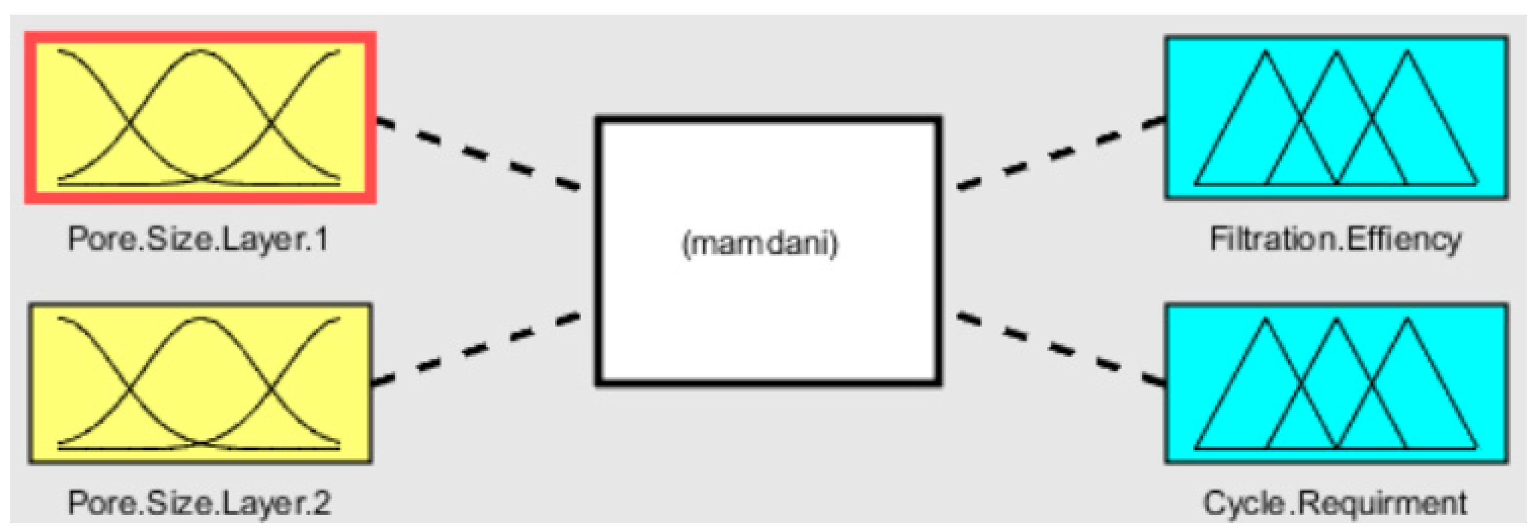
2.1. Fuzzy Analysis
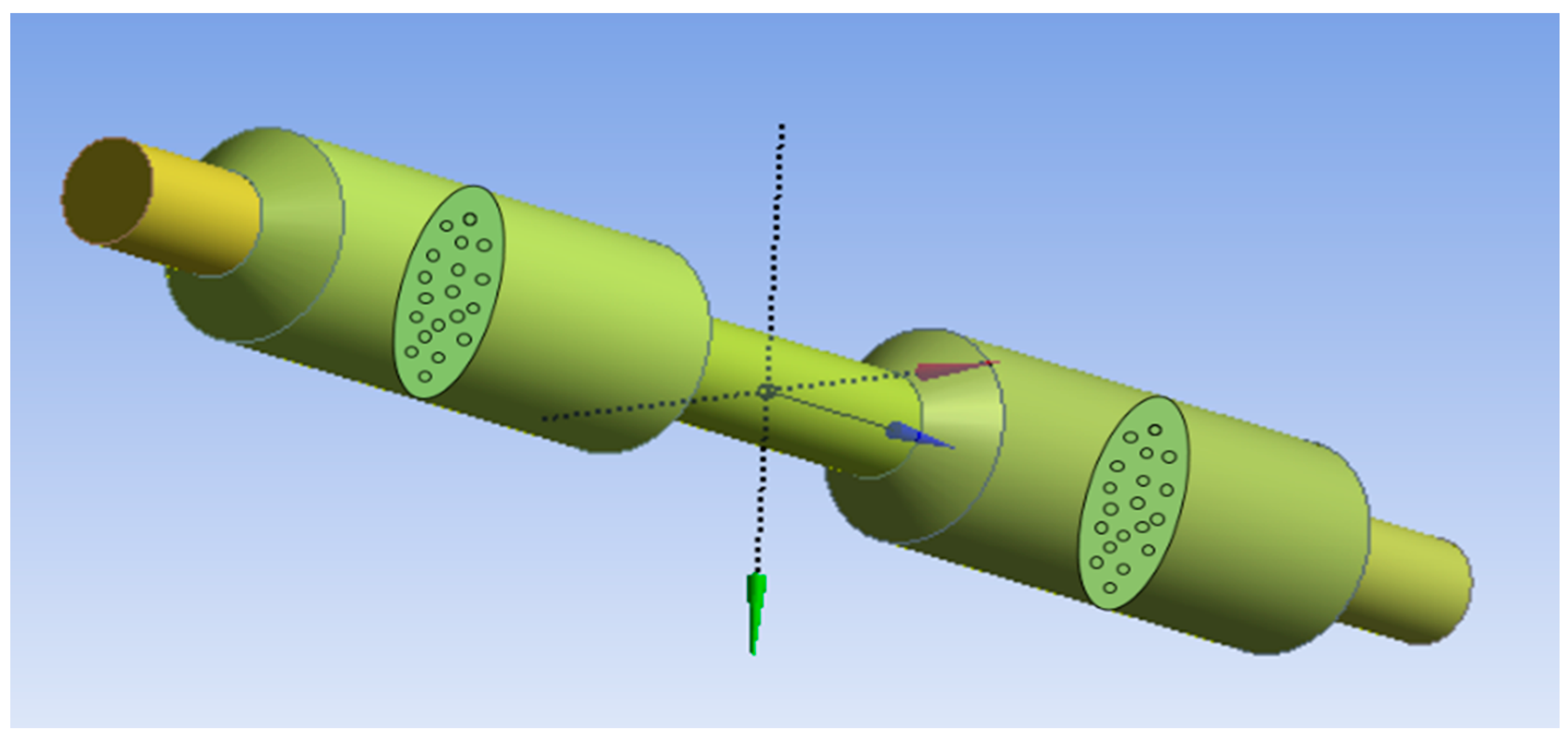
2.2. Microfluidic Simulation and Analysis
2.3. Fabrication of Anodic Aluminum Oxide Membrane
2.3.1. Materials
2.3.2. Methods
2.3.3. Characterization
2.4. Filtration Setup
3. Results and Discussion
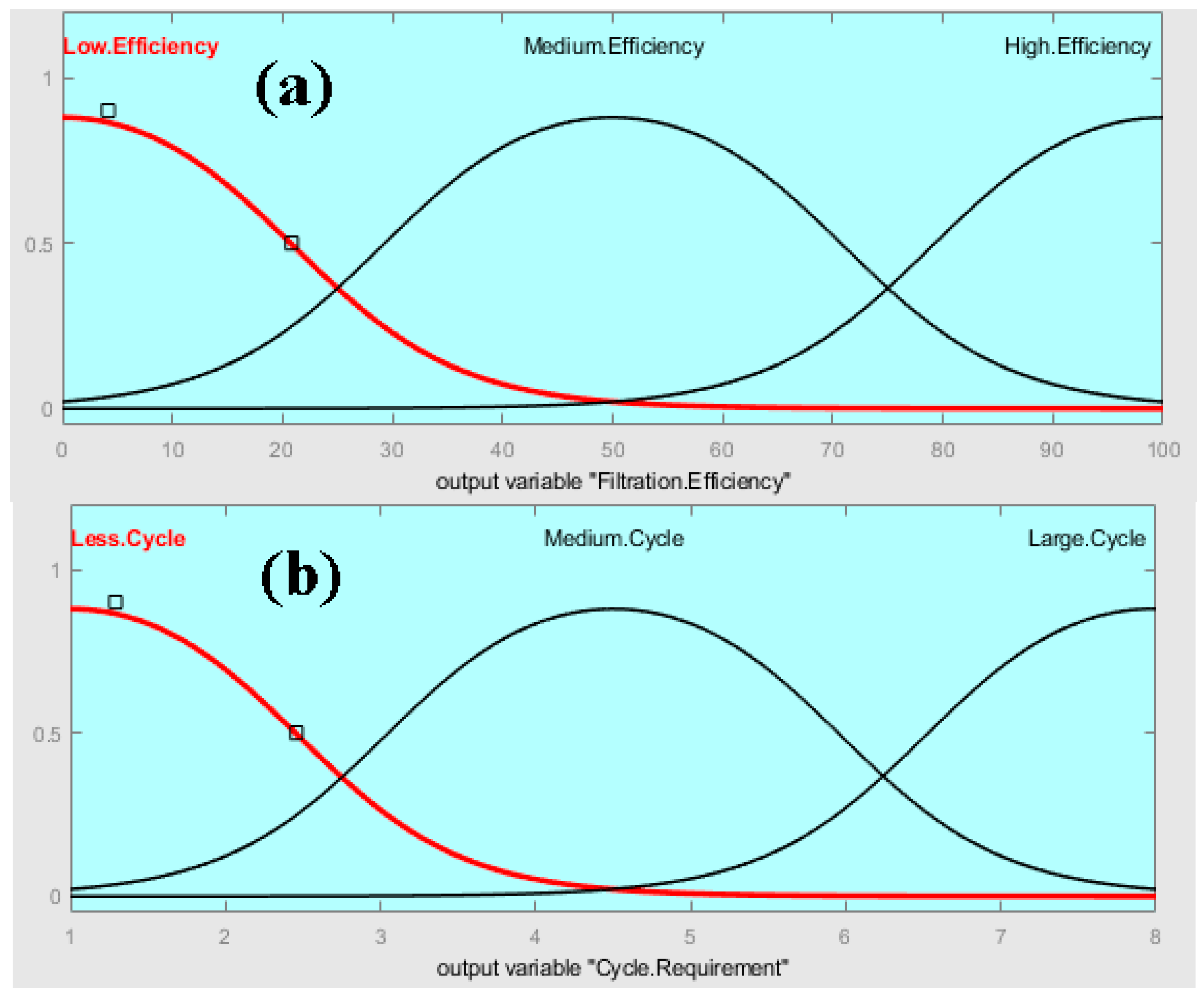
3.1. Fuzzy Analysis Results
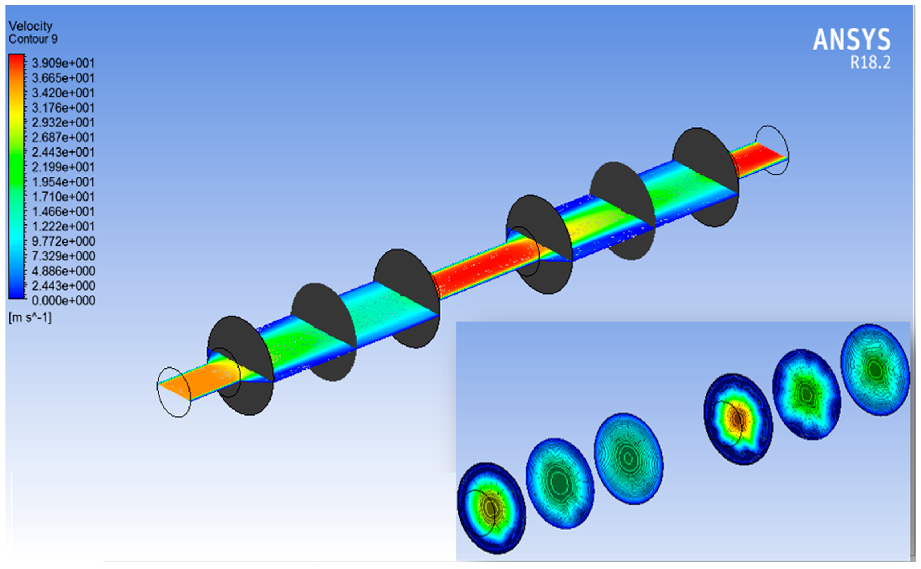
3.2. ANSYS Fluent Results
3.3. AAO Template Morphology Results
3.4. Filtration Analysis
4. Conclusions
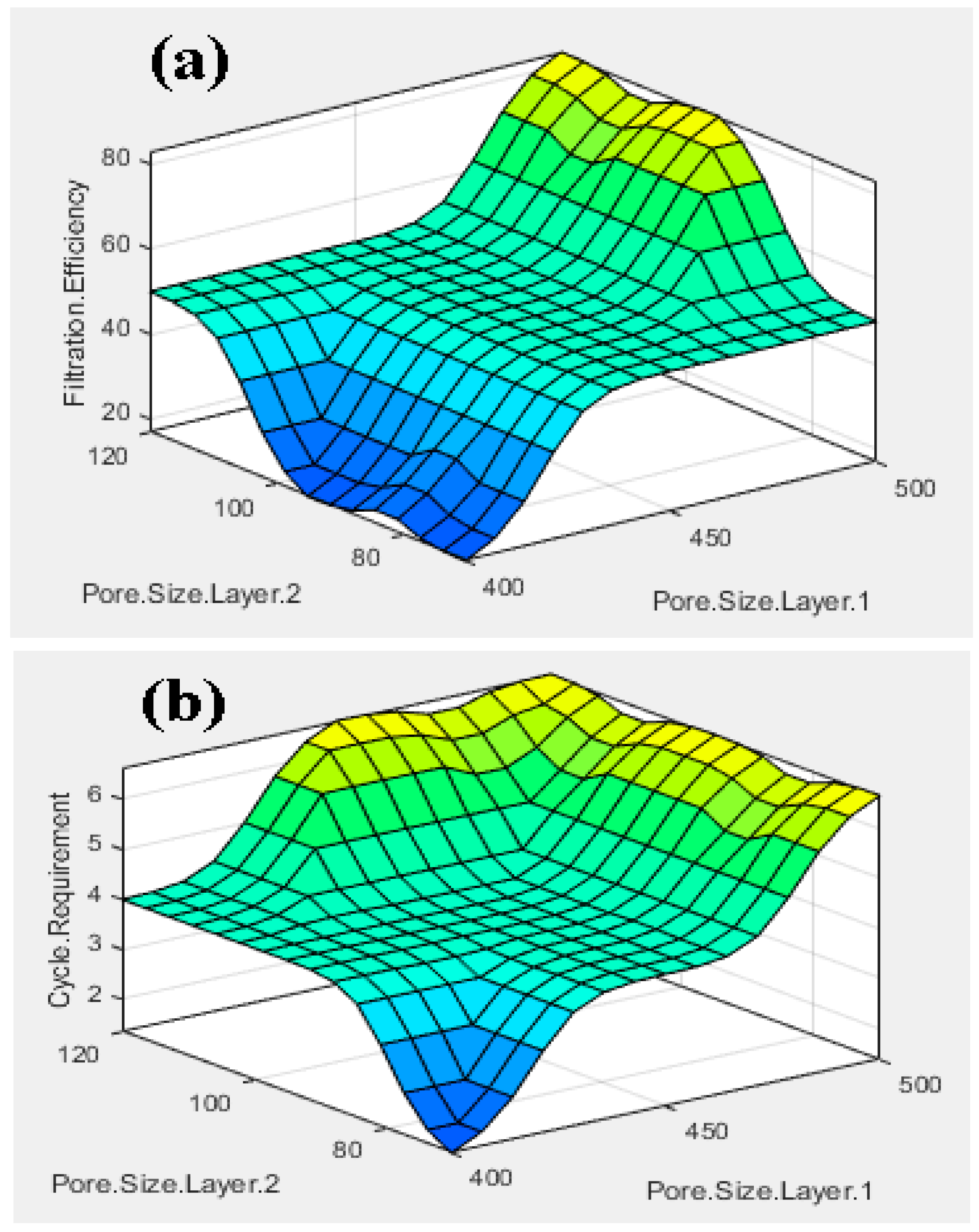
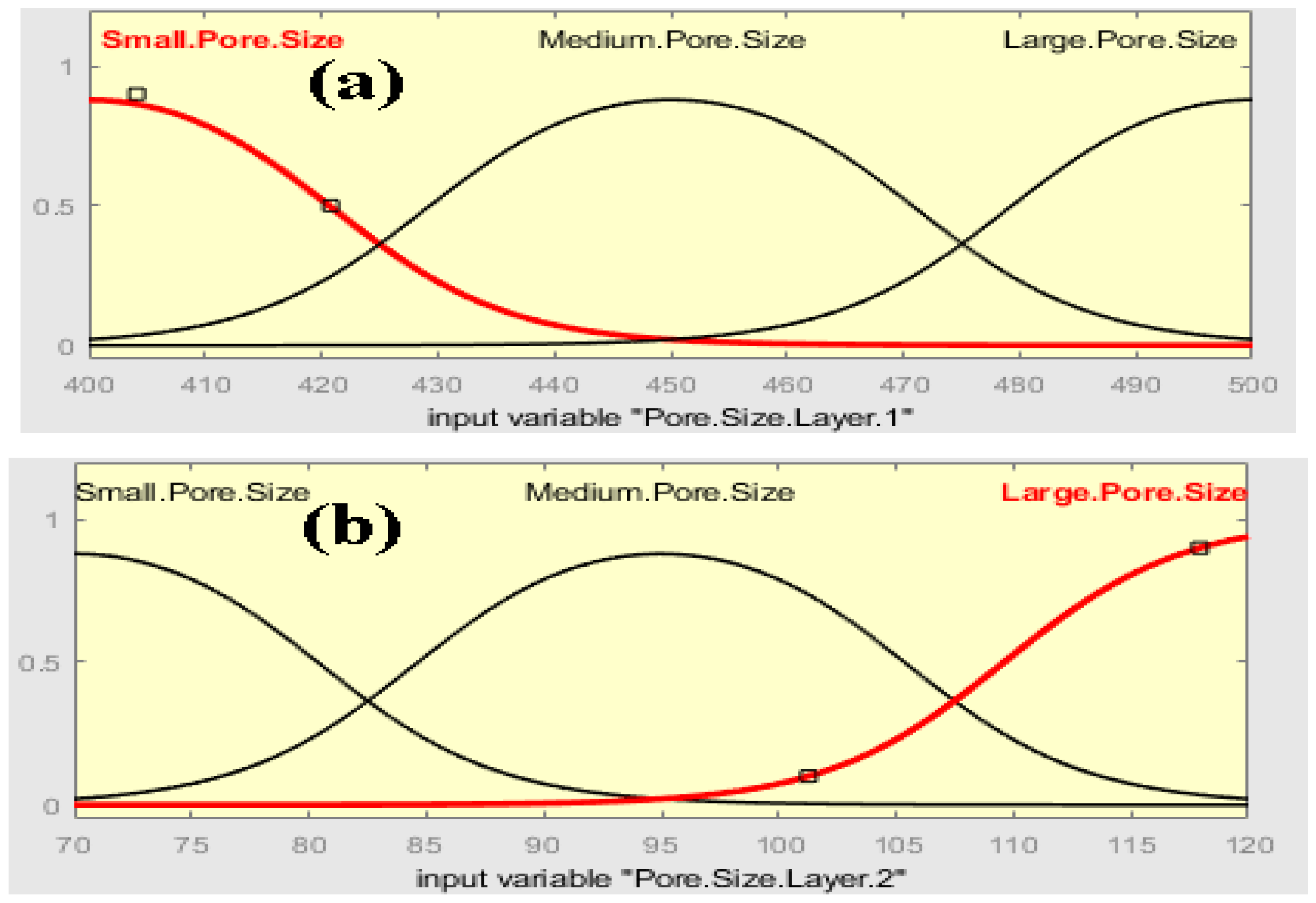
- The fuzzy-rule-based 3D graphs establish connections between the input pore size in Layer 1 and Layer 2, the filtration efficiency and the cycle requirements as outputs. The larger pore size in Layer 1 was found to enhance the removal of unwanted particles, resulting in pore blockage and the subsequent filtration of smaller contaminants, thereby improving filtration efficiency. The dual membranes were analyzed using soft computing techniques. A fuzzy analysis shows that the membrane pore size is a factor that greatly impacts the filtration efficiency and number of cycles required for purification. With larger pore size, more cycles can be taken for filtration, resulting in the better efficiency of the filtration process.
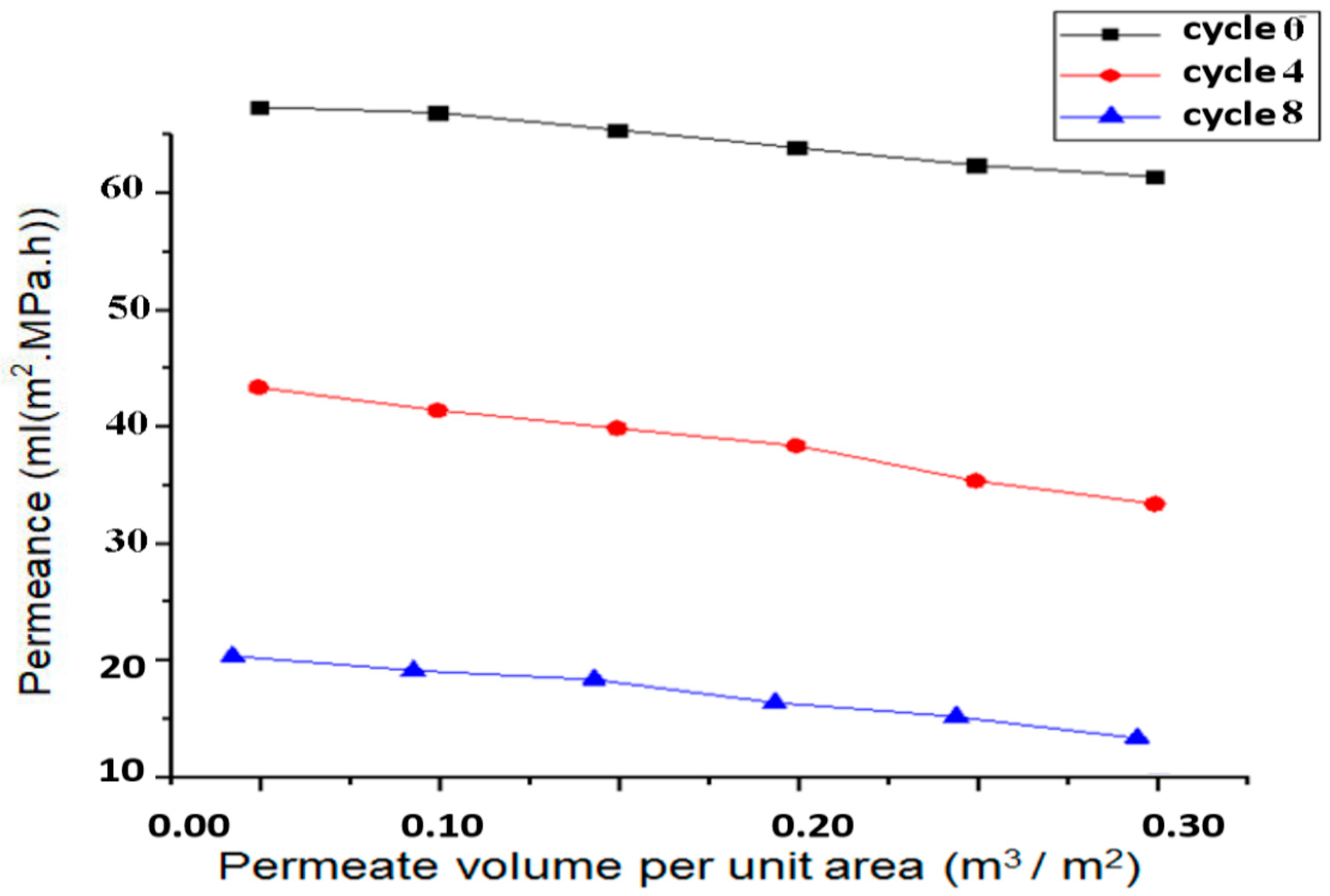
- The ANSYS simulation results shows that the fluidic flow reduces with an increase in the number of cycles, mainly due to the clogged pores due the impurities present in the samples. The permeance decreased as the filtration cycles progressed, primarily due to impurity-induced pore blockage.
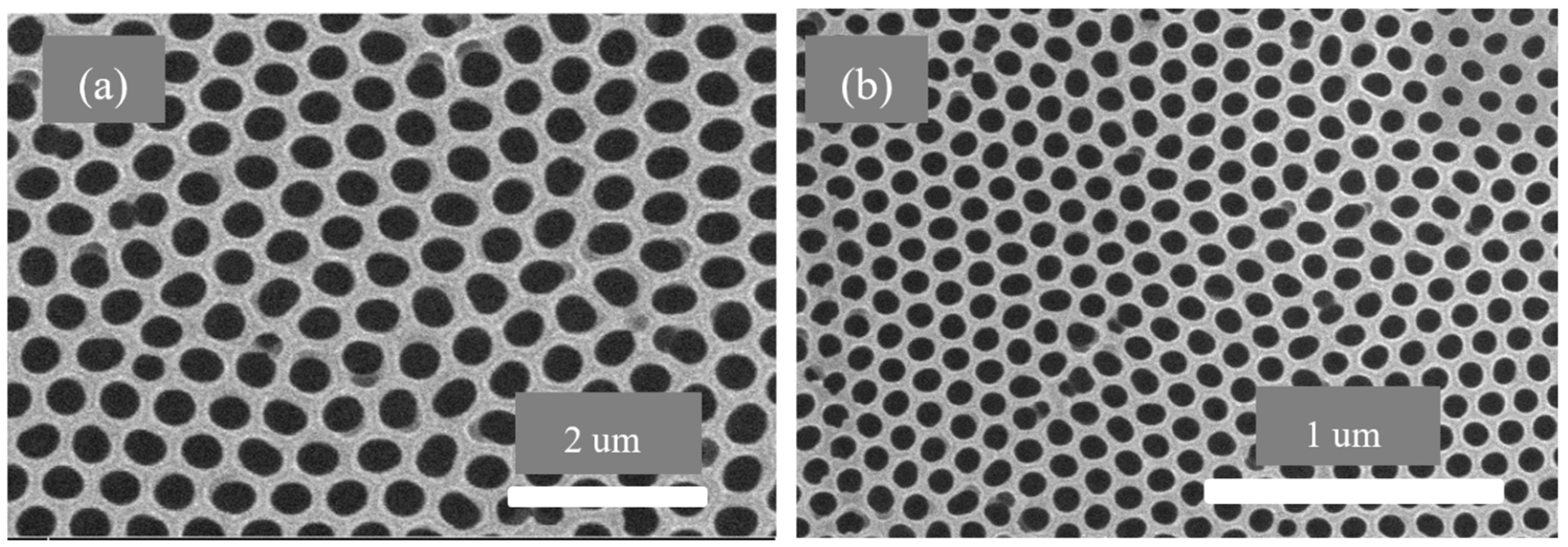
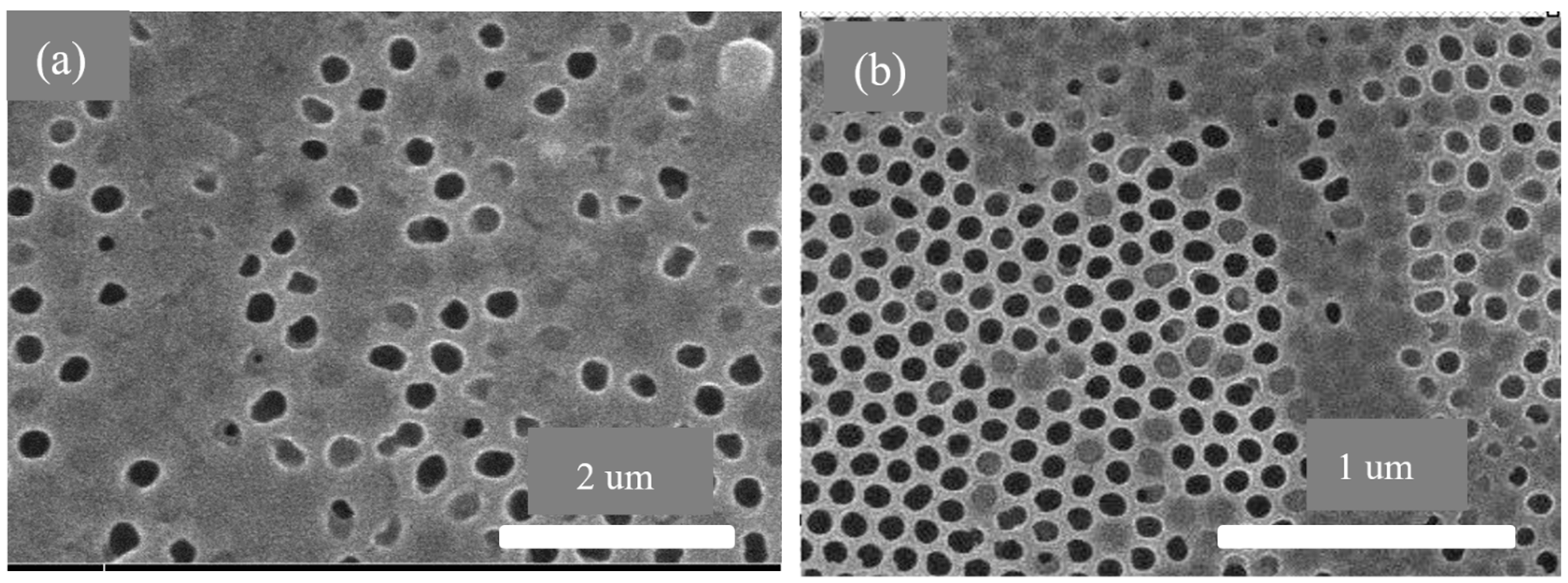
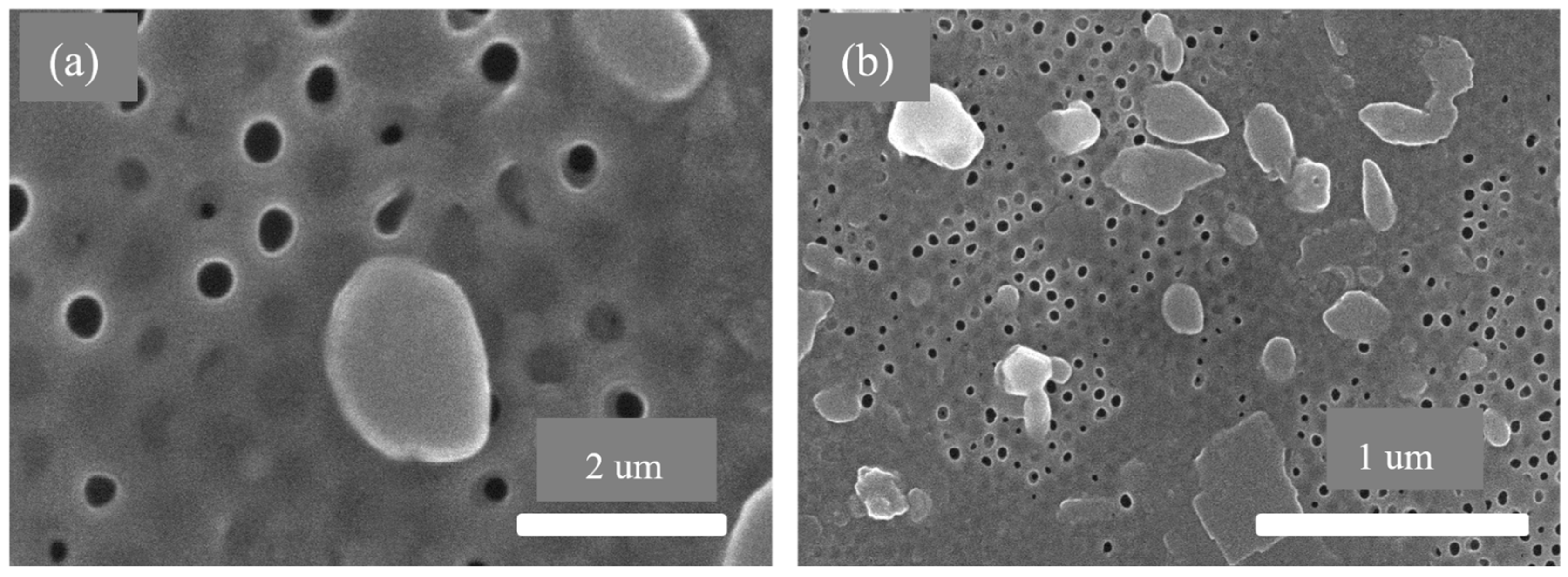
- The SEM results of the fabricated AAO membrane show the morphology of AAO membranes before filtration, featuring two layers with different pore sizes (400–500 nm and 70–120 nm). SEM images after four and eight filtration cycles demonstrated increased pore clogs and decreased flow rates, which is attributed to the accumulation of contaminants within the pores.
- Finally, the results show that the overall filtration efficiency can be improved using the dual AAO membranes in comparison to using single membrane. The number of cycles has been increased from four to eight, in comparison to from four to six as reported in the literature. This AAO low-cost membrane can be used effectively for fluid filtration in biomedical applications. The higher number of cycles for filtration gives more purified fluid.
Author Contributions
Funding
Data Availability Statement
Acknowledgments
Conflicts of Interest
References
- Erickson, D.; Li, D. Integrated microfluidic devices. Anal. Chim. Acta 2004, 507, 11–26. [Google Scholar]
- Yeo, L.Y.; Chang, H.-C.; Chan, P.P.Y.; Friend, J.R. Microfluidic Devices for Bioapplications. Small 2011, 7, 12–48. [Google Scholar] [CrossRef] [PubMed]
- Andersson, H.; van den Berg, A. Microfluidic devices for cellomics: A review. Sens. Actuators B Chem. 2003, 92, 315–325. [Google Scholar]
- Ayuso, J.M.; Virumbrales-Muñoz, M.; Lang, J.M.; Beebe, D.J. A role for microfluidic systems in precision medicine. Nat. Commun. 2022, 13, 3086. [Google Scholar] [PubMed]
- Liu, Y.; Yang, G.; Hui, Y.; Ranaweera, S.; Zhao, C. Microfluidic Nanoparticles for Drug Delivery. Small 2022, 18, e2106580. [Google Scholar]
- Sart, S.; Ronteix, G.; Jain, S.; Amselem, G.; Baroud, C.N. Cell Culture in Microfluidic Droplets. Chem. Rev. 2022, 122, 7061–7096. [Google Scholar] [CrossRef]
- Paul, L.; Hiremath, S.S. Model Prediction and Experimental Study of Material Removal Rate in Micro ECDM Process on Borosilicate Glass. Silicon 2021, 14, 1497–1510. [Google Scholar] [CrossRef]
- Konoplev, G.; Agafonova, D.; Bakhchova, L.; Mukhin, N.; Kurachkina, M.; Schmidt, M.-P.; Verlov, N.; Sidorov, A.; Oseev, A.; Stepanova, O.; et al. Label-Free Physical Techniques and Methodologies for Proteins Detection in Microfluidic Biosensor Structures. Biomedicines 2022, 10, 207. [Google Scholar] [CrossRef]
- Dai, C.; Liu, X.; Tang, R.; He, J.; Arai, T. A Review on Microfluidic Platforms Applied to Nerve Regeneration. Appl. Sci. 2022, 12, 3534. [Google Scholar] [CrossRef]
- Fallahi, H.; Zhang, J.; Phan, H.-P.; Nguyen, N.-T. Flexible microfluidics: Fundamentals, recent developments, and applications. Micromachines 2019, 10, 830. [Google Scholar] [CrossRef]
- Huang, Y.; Mather, E.L.; Bell, J.L.; Madou, M. MEMS-based sample preparation for molecular diagnostics. Anal. Bioanal. Chem. 2001, 372, 49–65. [Google Scholar] [CrossRef]
- Mirasoli, M.; Guardigli, M.; Michelini, E.; Roda, A. Recent advancements in chemical luminescence-based lab-on-chip and microfluidic platforms for bioanalysis. J. Pharm. Biomed. Anal. 2014, 87, 36–52. [Google Scholar] [PubMed]
- Scott, S.M.; Ali, Z. Fabrication Methods for Microfluidic Devices: An Overview. Micromachines 2021, 12, 319. [Google Scholar] [CrossRef] [PubMed]
- Santana, H.S.; Silva, J.L.; Aghel, B.; Ortega-Casanova, J. Review on microfluidic device applications for fluids separation and water treatment processes. SN Appl. Sci. 2020, 2, 395. [Google Scholar]
- Mathekga, B.S.; Nxumalo, Z.; Raj, D.B.T.G. Micro and nanofluidics for high throughput drug screening. Prog. Mol. Biol. Transl. Sci. 2022, 187, 93–120. [Google Scholar] [PubMed]
- de Jong, J.; Lammertink, R.G.H.; Wessling, M. Membranes and microfluidics: A review. Lab Chip 2006, 6, 1125–1139. [Google Scholar] [PubMed]
- Mou, L.; Jiang, X. Materials for microfluidic immunoassays: A review. Adv. Healthc. Mater. 2017, 6, 1601403. [Google Scholar] [CrossRef]
- Luo, J.; Fan, J.; Wang, S. Recent Progress of Microfluidic Devices for Hemodialysis. Small 2020, 16, e1904076. [Google Scholar] [CrossRef]
- Manzoor, S.; Tayyaba, S.; Ashraf, M.W. Simulation, analysis, fabrication and characterization of tunable AAO membrane for microfluidic filtration. J. Intell. Fuzzy Syst. 2022, 43, 2099–2108. [Google Scholar] [CrossRef]
- Chen, X.; Shen, J.; Hu, Z.; Huo, X. Manufacturing methods and applications of membranes in microfluidics. Biomed. Microdevices 2016, 18, 104. [Google Scholar]
- Manzoor, S.; Ashraf, M.W.; Tayyaba, S.; Tariq, M.I.; Hossain, M.K. Recent Progress of Fabrication, Characterization, and Applications of Anodic Aluminum Oxide (AAO) Membrane: A Review. Comput. Model. Eng. Sci. 2023, 135, 1007–1052. [Google Scholar]
- Poznyak, A.; Knörnschild, G.; Karoza, A.; Norek, M.; Pligovka, A. Peculiar Porous Aluminum Oxide Films Produced via Electrochemical Anodizing in Malonic Acid Solution with Arsenazo-I Additive. Materials 2021, 14, 5118. [Google Scholar] [CrossRef] [PubMed]
- Wen, F.-Y.; Chen, P.-S.; Liao, T.-W.; Juang, Y.-J. Microwell-assisted filtration with anodic aluminum oxide membrane for Raman analysis of algal cells. Algal Res. 2018, 33, 412–418. [Google Scholar] [CrossRef]
- Patel, Y.; Janusas, G.; Palevicius, A.; Vilkauskas, A. Development of Nanoporous AAO Membrane for Nano Filtration Using the Acoustophoresis Method. Sensors 2020, 20, 3833. [Google Scholar] [CrossRef]
- Aminullah; Kasi, A.K.; Kasi, J.K.; Bokhari, M. Fabrication of mechanically stable AAO membrane with improved fluid permeation properties. Microelectron. Eng. 2018, 187–188, 95–100. [Google Scholar] [CrossRef]
- Pawlowski, S.W.; Warren, C.A.; Guerrant, R. Diagnosis and Treatment of Acute or Persistent Diarrhea. Gastroenterology 2009, 136, 1874–1886. [Google Scholar]
- Cabral, J.P.S. Water Microbiology. Bacterial Pathogens and Water. Int. J. Environ. Res. Public Health 2010, 7, 3657–3703. [Google Scholar] [CrossRef]
- Kawashima, K.; Shirzadi, M.; Fukasawa, T.; Fukui, K.; Tsuru, T.; Ishigami, T. Numerical modeling for particulate flow through realistic microporous structure of microfiltration membrane: Direct numerical simulation coordinated with focused ion beam scanning electron microscopy. Powder Technol. 2022, 410, 117872. [Google Scholar] [CrossRef]
- Tanudjaja, H.J.; Chew, J.W. Application of Machine Learning-Based Models to Understand and Predict Critical Flux of Oil-in-Water Emulsion in Crossflow Microfiltration. Ind. Eng. Chem. Res. 2022, 61, 8470–8477. [Google Scholar] [CrossRef]
- Qamar, A.; Bucs, S.; Picioreanu, C.; Vrouwenvelder, J.; Ghaffour, N. Hydrodynamic flow transition dynamics in a spacer filled filtration channel using direct numerical simulation. J. Membr. Sci. 2019, 590, 117264. [Google Scholar]
- Rahimzadeh, A.; Ashtiani, F.Z.; Okhovat, A. Application of adaptive neuro-fuzzy inference system as a reliable approach for prediction of oily wastewater microfiltration permeate volume. J. Environ. Chem. Eng. 2016, 4, 576–584. [Google Scholar] [CrossRef]
- Bocchetta, P.; Santamaria, M.; Di Quarto, F. Electrosynthesis of Ce–Co Mixed Oxide Nanotubes with High Aspect Ratio and Tunable Composition. Electrochem. Solid-State Lett. 2008, 11, K27–K30. [Google Scholar] [CrossRef]
- Poznyak, A.A.; Knörnschild, G.H.; Pligovka, A.N.; Larin, T.D. Anodic Alumina Prepared in Aqueous Solutions of Chelating Complex Zinc and Cobalt Compounds. Tech. Phys. 2022, 67, 411–422. [Google Scholar] [CrossRef]
- Suru, T. Inorganic Porous Membranes for Liquid Phase Separation. Sep. Purif. Methods 2001, 30, 191–220. [Google Scholar] [CrossRef]
- Wendorff, J.H.; Agarwal, S.; Greiner, A. Electrospinning—Some Technical Aspects. In Electrospinning: Materials, Processing, and Application; John Wiley & Sons: Weinheim, Germany, 2012; Chapter 5; pp. 127–142. [Google Scholar]
- Gong, D.; Grimes, C.A.; Varghese, O.K.; Hu, W.; Singh, R.S.; Chen, Z.; Dickey, E.C. Titanium oxide nanotube arrays prepared by anodic oxidation. J. Mater. Res. 2001, 16, 3331–3334. [Google Scholar] [CrossRef]
- Wu, Z.; Richter, C.; Menon, L. A Study of Anodization Process during Pore Formation in Nanoporous Alumina Templates. J. Electrochem. Soc. 2007, 154, E8. [Google Scholar] [CrossRef]
- Lee, W. The anodization of aluminum for nanotechnology applications. JOM 2010, 62, 57–63. [Google Scholar] [CrossRef]
- Macias, G.; Hernández-Eguía, L.P.; Ferré-Borrull, J.; Pallares, J.; Marsal, L.F. Gold-Coated Ordered Nanoporous Anodic Alumina Bilayers for Future Label-Free Interferometric Biosensors. ACS Appl. Mater. Interfaces 2013, 5, 8093–8098. [Google Scholar] [CrossRef]
- Diggle, J.W.; Downie, T.C.; Goulding, C.W. Anodic oxide films on aluminum. Chem. Rev. 1969, 69, 365–405. [Google Scholar] [CrossRef]
- Poinern, G.E.J.; Ali, N.; Fawcett, D. Progress in Nano-Engineered Anodic Aluminum Oxide Membrane Development. Materials 2011, 4, 487–526. [Google Scholar] [CrossRef]
- Vorozhtsova, M.; Drbohlavova, J.; Hubalek, J. Microsensors with Ordered Nanostructures. In Microsensors; Minin, I., Ed.; IntechOpen: London, UK, 2011. [Google Scholar]
- Tsuchiya, H.; Schmuki, P. Thick self-organized porous zirconium oxide formed in H2SO4/NH4F electrolytes. Electrochem. Commun. 2004, 6, 1131–1134. [Google Scholar] [CrossRef]
- Shimizu, K.; Habazaki, H.; Skeldon, P.; Thompson, G.E.; Wood, G.C. Comparison of depth profiling analysis of a thick, electrolytically-colored porous alumina film by EPMA and GDOES. Surf. Interface Anal. 1999, 27, 1046–1049. [Google Scholar] [CrossRef]
- Vida-Simiti, I.; Nemes, D.; Jumate, N.; Thalmaier, G.; Sechel, N. Self-Ordered Nanoporous Alumina Templates Formed by Anodization of Aluminum in Oxalic Acid. JOM 2012, 64, 1143–1147. [Google Scholar] [CrossRef]
- Giacobbo, A.; Pasqualotto, I.F.; Machado Filho, R.C.D.C.; Minhalma, M.; Bernardes, A.M.; Pinho, M.N.d. Ultrafiltration and Nanofiltration for the Removal of Pharmaceutically Active Compounds from Water: The Effect of Operating Pressure on Electrostatic Solute–Membrane Interactions. Membranes 2023, 13, 743. [Google Scholar] [CrossRef]
- Lee, C.T.; Comer, J.; Herndon, C.; Leung, N.; Pavlova, A.; Swift, R.V.; Tung, C.; Rowley, C.N.; Amaro, R.E.; Chipot, C.; et al. Simulation-Based Approaches for Determining Membrane Permeability of Small Compounds. J. Chem. Inf. Model. 2016, 56, 721–733. [Google Scholar] [CrossRef] [PubMed]
- Lindahl, E.; Sansom, M.S. Membrane proteins: Molecular dynamics simulations. Curr. Opin. Struct. Biol. 2008, 18, 425–431. [Google Scholar] [CrossRef] [PubMed]
- Song, J.; Oh, H.; Kong, H.; Jang, J. Polyrhodanine modified anodic aluminum oxide membrane for heavy metal ions removal. J. Hazard. Mater. 2011, 187, 311–317. [Google Scholar] [CrossRef]
- Hun, C.W.; Chiu, Y.-J.; Luo, Z.; Chen, C.C.; Chen, S.H. A New Technique for Batch Production of Tubular Anodic Aluminum Oxide Films for Filtering Applications. Appl. Sci. 2018, 8, 1055. [Google Scholar] [CrossRef]
- Huang, X.; Mutlu, H.; Theato, P. A CO2-gated anodic aluminum oxide based nanocomposite membrane for de-emulsification. Nanoscale 2020, 12, 21316–21324. [Google Scholar] [CrossRef]
- Phuong, N.; Andisetiawan, A.; Van Lam, D.; Kim, J.H.; Choi, D.-S.; Whang, K.-H.; Nham, J.; Lee, Y.J.; Yoo, Y.-E.; Yoon, J.S. Nano sand filter with functionalized nanoparticles embedded in anodic aluminum oxide templates. Sci. Rep. 2016, 6, 37673. [Google Scholar]


| Quantities | Filtration Efficiency (%) | Cycle Requirement (Number) |
|---|---|---|
| Simulated Value | 64.6 | 5.89 |
| Calculated Value | 64.65 | 5.88 |
| Error | 0.05 | 0.01 |
| Reference | Membrane Type | Number of Layers for the Membrane | Pore Size (nm) | Fluid Flow Velocity/Flux | Filtration Application |
|---|---|---|---|---|---|
| Aminullah 2018 [25] | Al-textured AAO membrane | Single | 31.25 | Fluid flow velocity dependent on the viscosity of the fluid | Flow of fluid, permeability of acetone, ethanol, dimethylformamide, methanol, cyclohexane, isopropyl alcohol, water and n-butanol |
| Jooyoung 2011 [49] | Polyrhodanine-modified anodic aluminum oxide membrane | Single | 150 | - | Removal of heavy metal ions from wastewater |
| Chein 2018 [50] | Tubular AAO films | Single | 60 | - | Drug delivery, liquid filters, gas filters and energy applications |
| Yatinkumar 2020 [24] | Nanoporous AAO Membrane | Single | 50–90 | - | Nano-filtration |
| Huang 2020 [51] | CO2-gated AAO-based nanocomposite membrane | Single | 210–260 | Flux—50–500 L m−2 h−1 | De-emulsification |
| Phuong 2016 [52] | Functionalized nanoparticles embedded in anodic aluminum oxide templates | Single | 150 | Flux—48.19 g/sm2 | Sand filtration |
| Manzoor [19] | Tunable AAO membrane | Single | 50–100 | Fluid flow velocity 0–3 cm/s | Microfludic filtration for biomedical application |
| Presented work | Dual-layer AAO membrane | Double | 70–500 | Fluid flow velocity 0–4 cm/s | Contaminated fluid purification for biomedical application |
Disclaimer/Publisher’s Note: The statements, opinions and data contained in all publications are solely those of the individual author(s) and contributor(s) and not of MDPI and/or the editor(s). MDPI and/or the editor(s) disclaim responsibility for any injury to people or property resulting from any ideas, methods, instructions or products referred to in the content. |
© 2023 by the authors. Licensee MDPI, Basel, Switzerland. This article is an open access article distributed under the terms and conditions of the Creative Commons Attribution (CC BY) license (https://creativecommons.org/licenses/by/4.0/).
Share and Cite
Qasim, F.; Ashraf, M.W.; Tayyaba, S.; Tariq, M.I.; Herrera-May, A.L. Simulation, Fabrication and Microfiltration Using Dual Anodic Aluminum Oxide Membrane. Membranes 2023, 13, 825. https://doi.org/10.3390/membranes13100825
Qasim F, Ashraf MW, Tayyaba S, Tariq MI, Herrera-May AL. Simulation, Fabrication and Microfiltration Using Dual Anodic Aluminum Oxide Membrane. Membranes. 2023; 13(10):825. https://doi.org/10.3390/membranes13100825
Chicago/Turabian StyleQasim, Faheem, Muhammad Waseem Ashraf, Shahzadi Tayyaba, Muhammad Imran Tariq, and Agustín L. Herrera-May. 2023. "Simulation, Fabrication and Microfiltration Using Dual Anodic Aluminum Oxide Membrane" Membranes 13, no. 10: 825. https://doi.org/10.3390/membranes13100825
APA StyleQasim, F., Ashraf, M. W., Tayyaba, S., Tariq, M. I., & Herrera-May, A. L. (2023). Simulation, Fabrication and Microfiltration Using Dual Anodic Aluminum Oxide Membrane. Membranes, 13(10), 825. https://doi.org/10.3390/membranes13100825