
Enhanced Removal of Endocrine-Disrupting Compounds from Wastewater Using Reverse Osmosis Membrane with Titania Nanotube-Constructed Nanochannels


 ,
,  , , and
Abstract
:1. Introduction
2. Materials and Methods
2.1. Materials
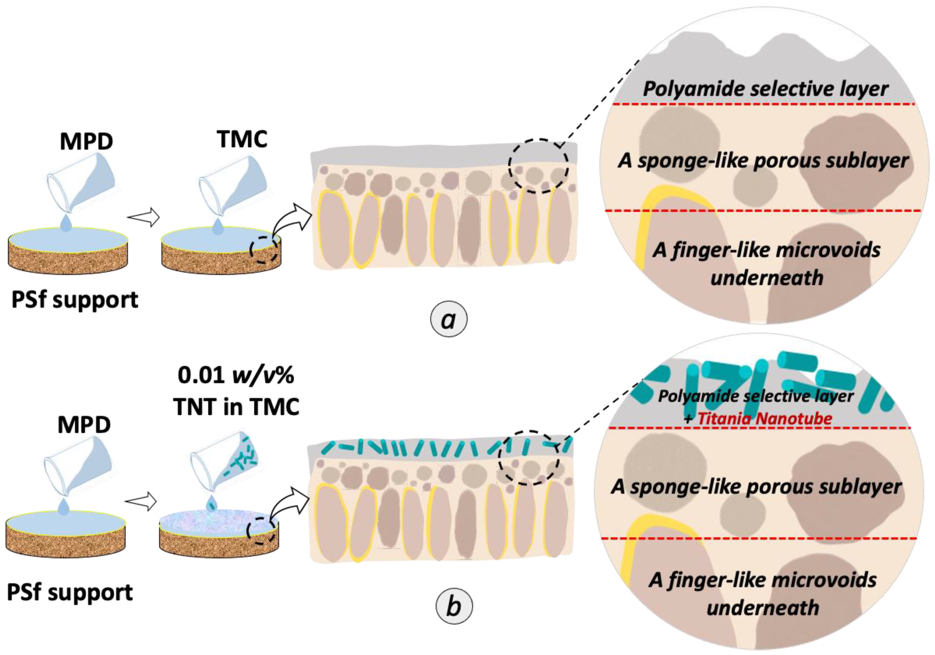
2.2. Fabrication of TFC and TFN Membranes
2.3. Characterizations
2.4. Evaluation of TFC and TFN Membrane Performance
2.4.1. Feed Water Characteristics
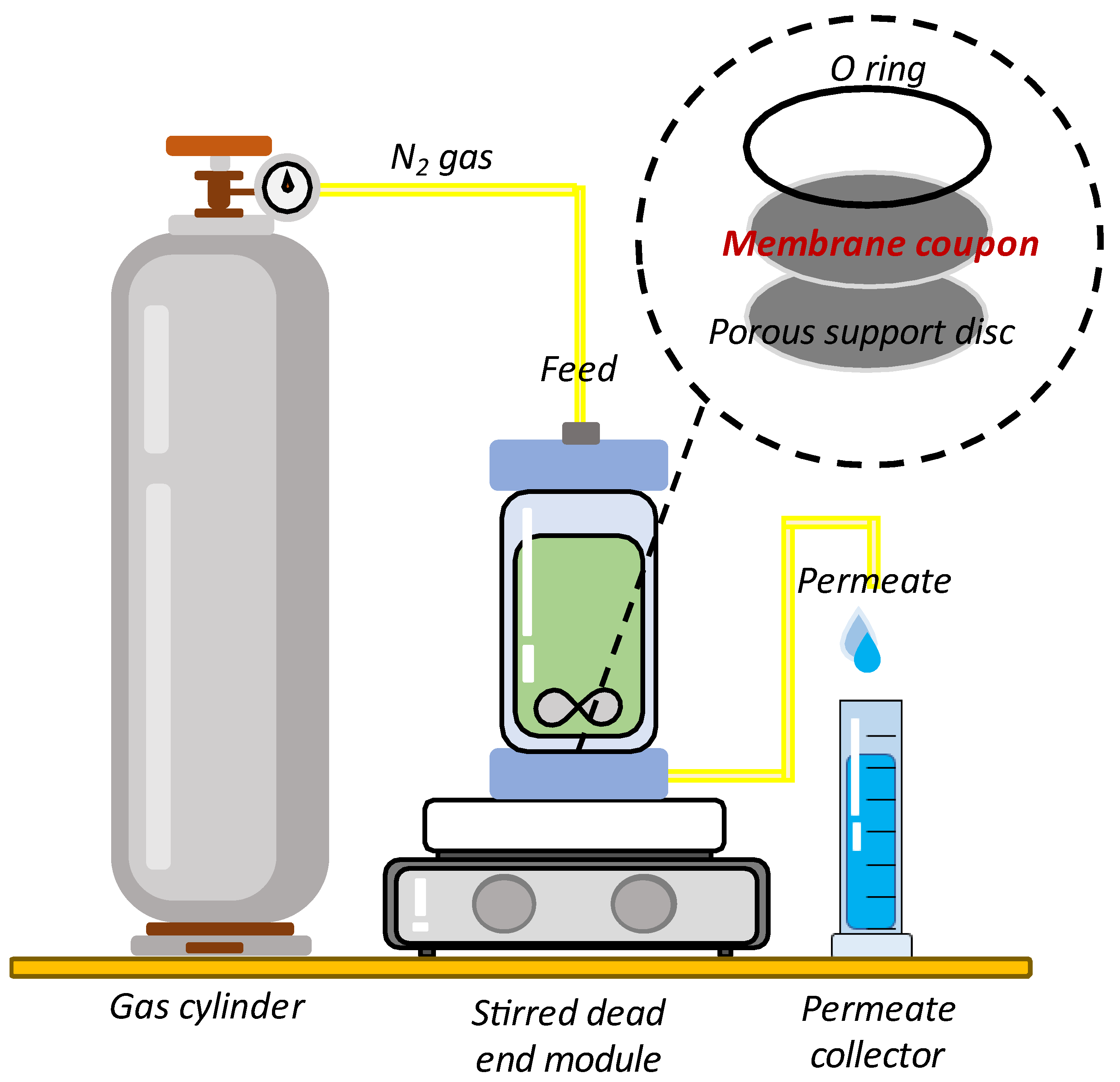
2.4.2. Water Permeability and Rejection Test of Saline Water
2.4.3. Water Permeability and Rejection Test of BPA and Caffeine Solution
2.4.4. Antifouling Assessment
3. Result and Discussion
3.1. Properties of Titania Nanotube
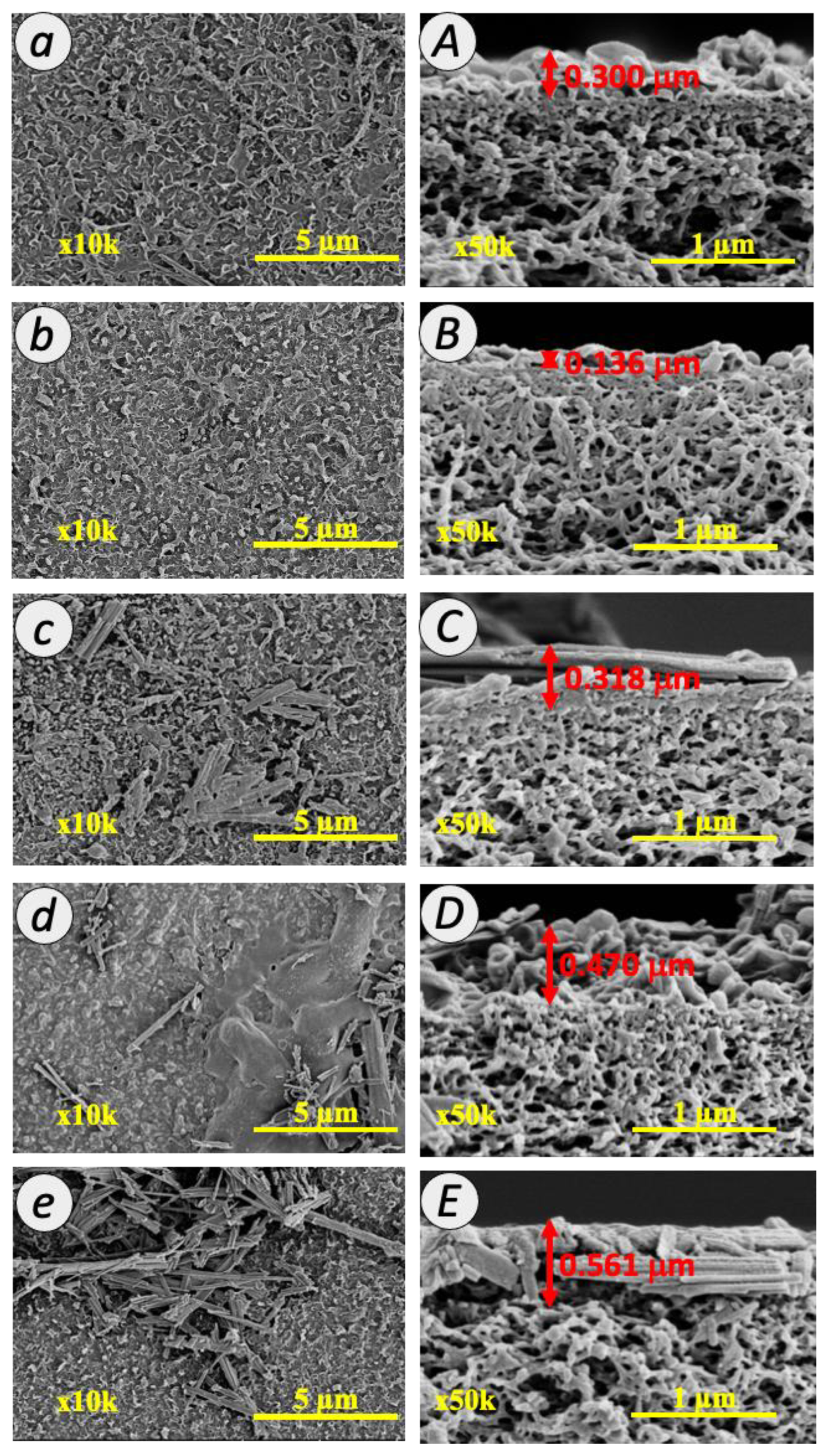
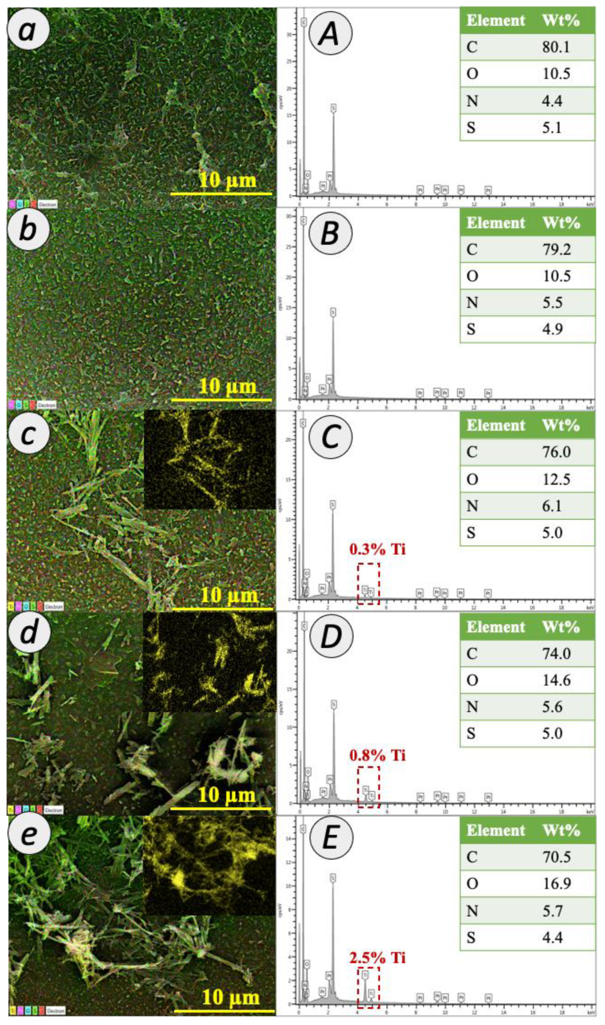
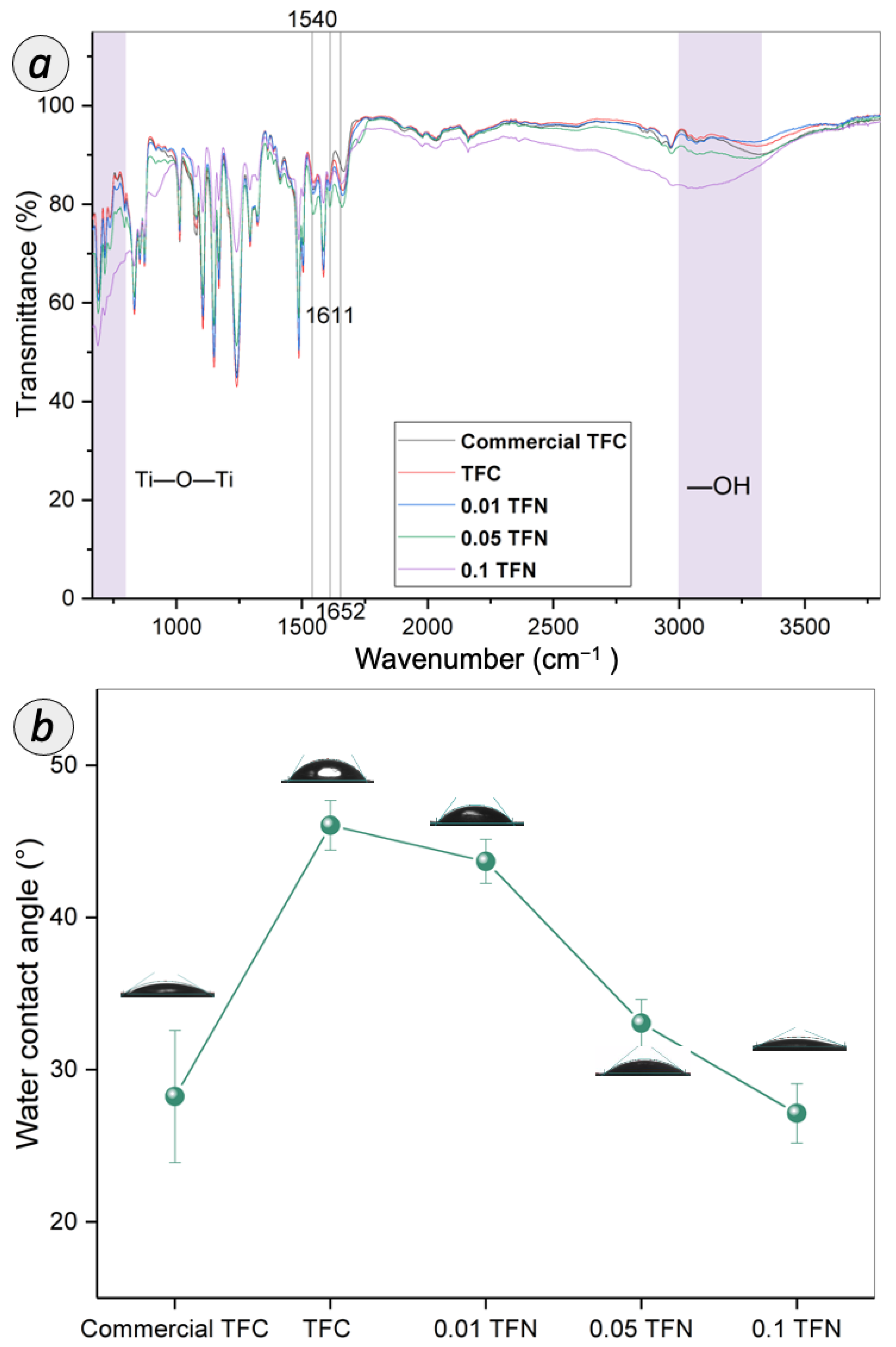
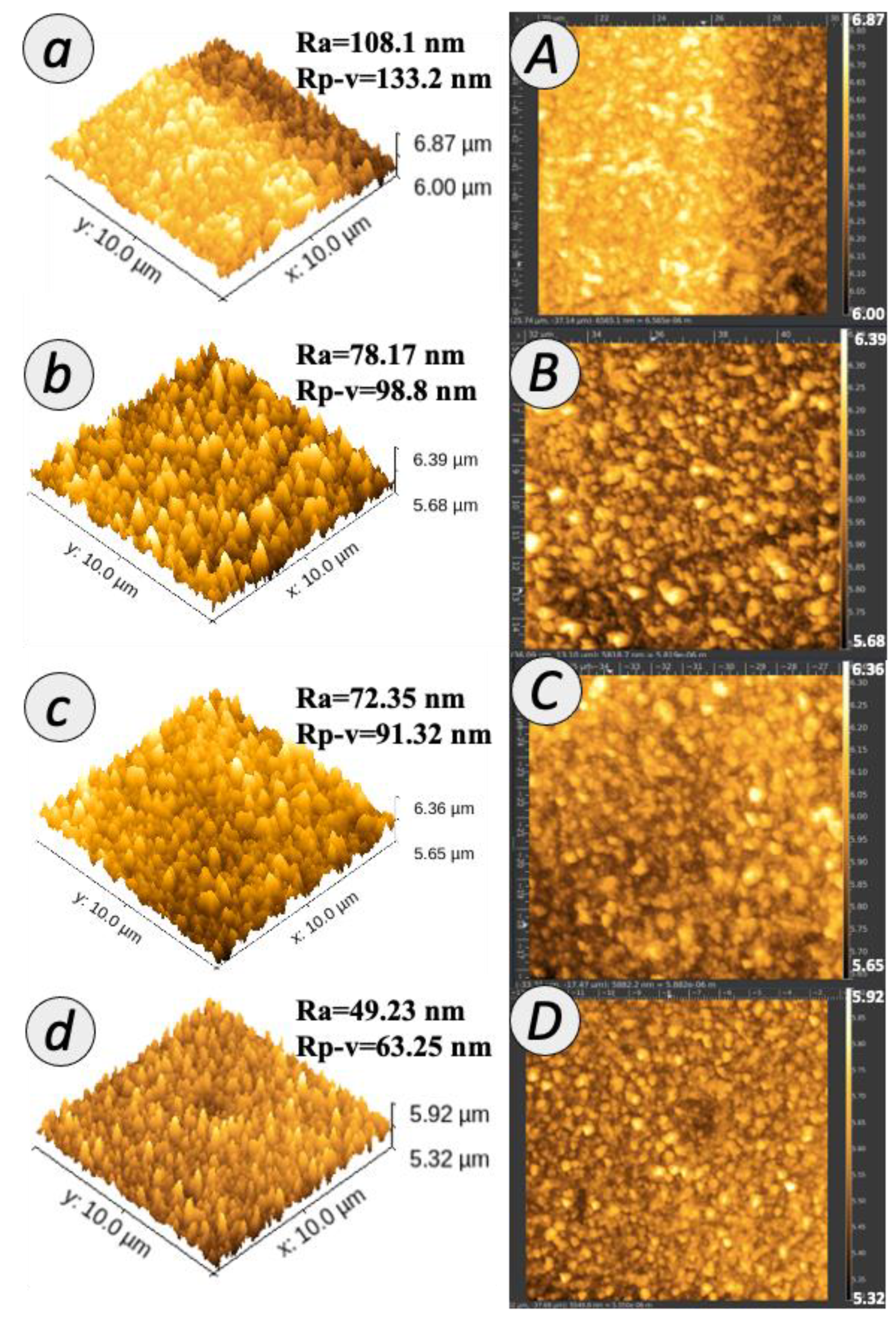
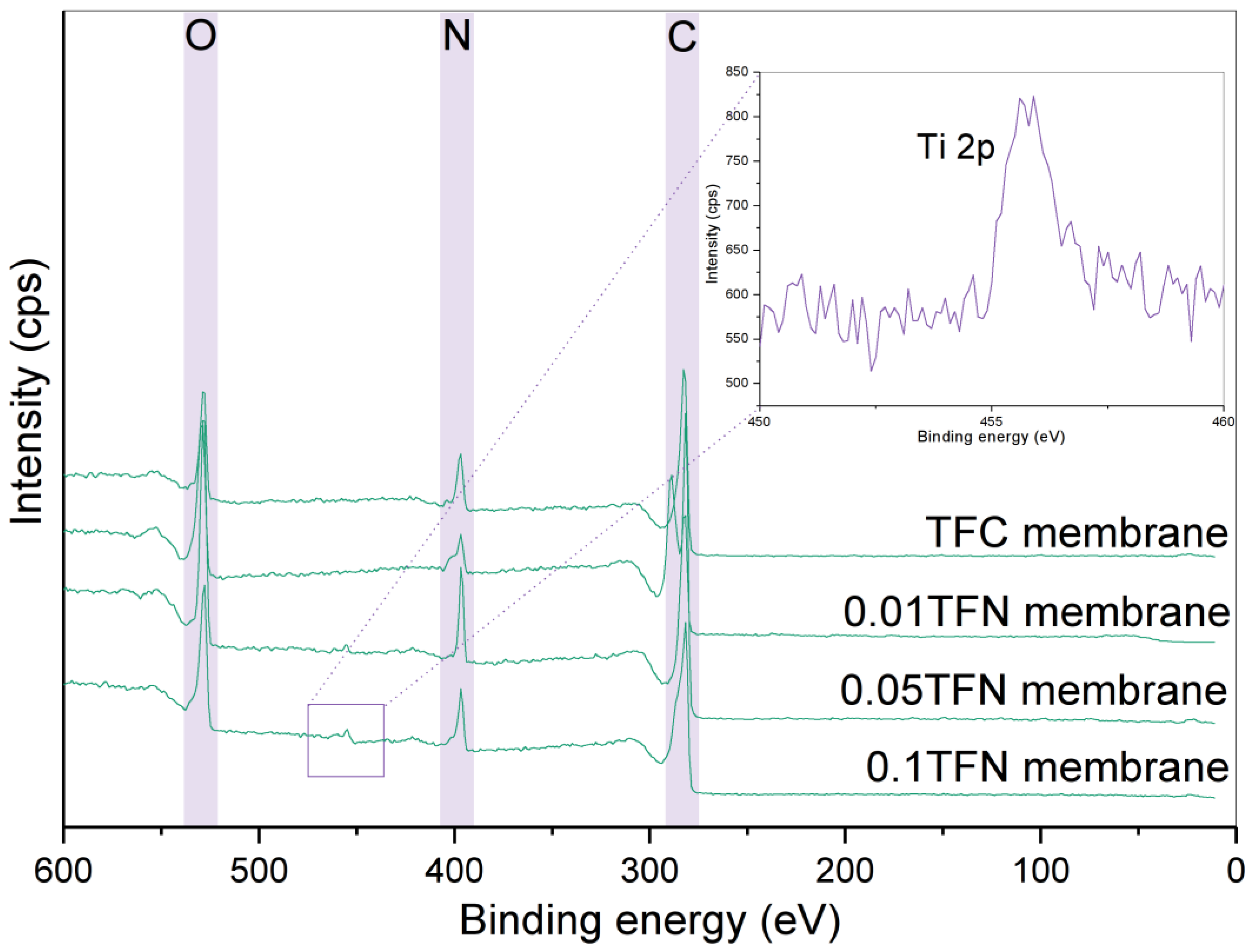
3.2. Characteristics of TFC and TFN Membranes
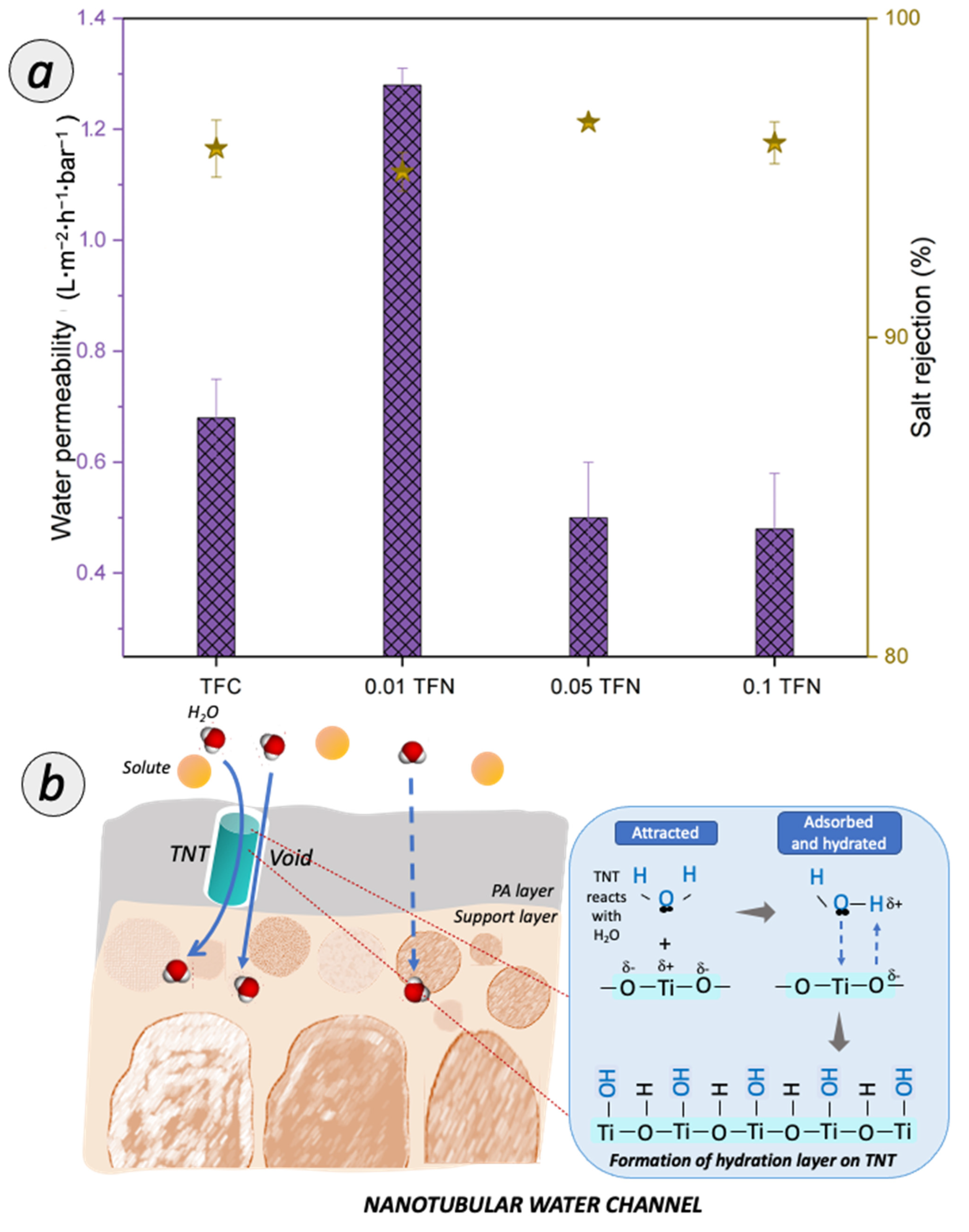
3.3. Membrane Separation Performance
3.3.1. Salt Removal Efficiency
3.3.2. RO BPA and Caffeine Separation
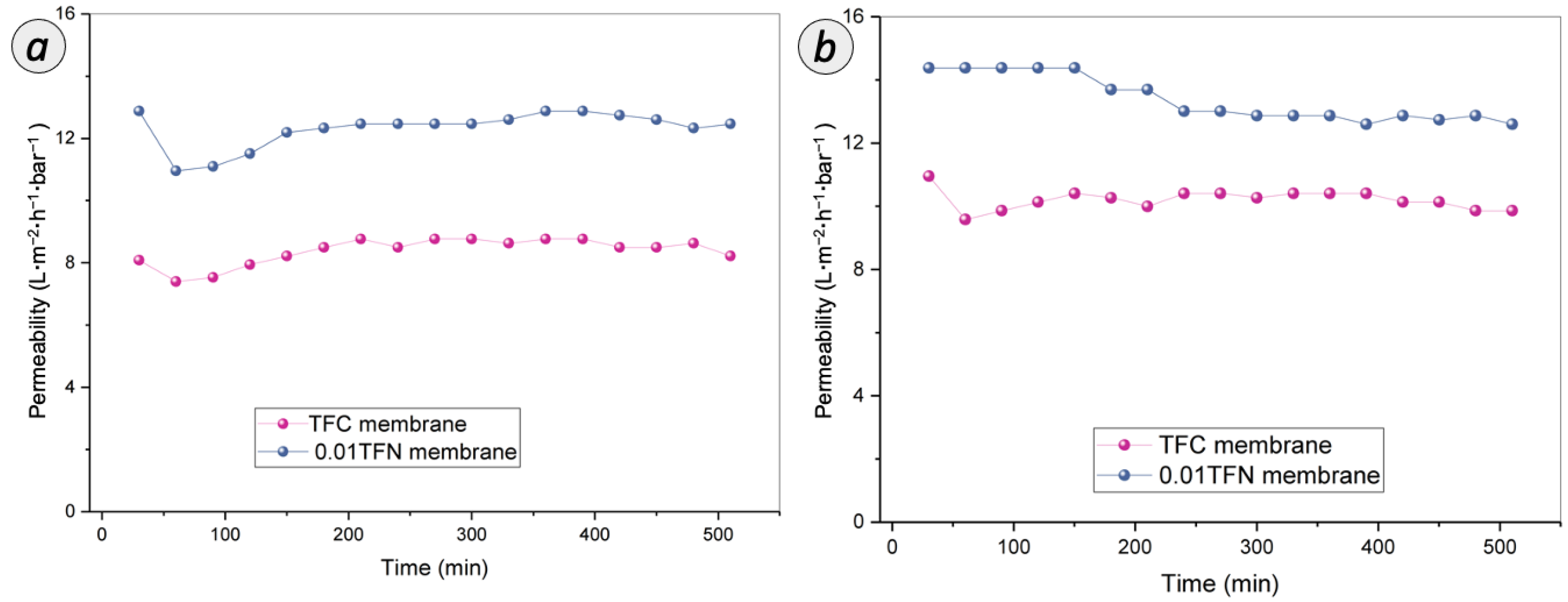
3.3.3. Antifouling Assessment on RO Membranes
3.3.4. Benchmarking with Other Studies
4. Conclusions
Supplementary Materials
Author Contributions
Funding
Data Availability Statement
Conflicts of Interest
References
- Kim, M.; Zoh, K. Occurrence and removals of micropollutants in water environment. Environ. Eng. Res. 2016, 21, 319–332. [Google Scholar] [CrossRef]
- Chambers, C.; Stewart, S.B.; Su, B.; Jenkinson, H.F.; Sandy, J.R.; Ireland, A.J. Silver doped titanium dioxide nanoparticles as antimicrobial additives to dental polymers. Dent. Mater. 2017, 33, 115–123. [Google Scholar] [CrossRef] [PubMed]
- Huang, W.; Hu, Y.; Li, Y.; Zhou, Y.; Niu, D. Citric acid-crosslinked β-cyclodextrin for simultaneous removal of bisphenol A, methylene blue and copper: The roles of cavity and surface functional groups. J. Taiwan Inst. Chem. Eng. 2018, 82, 189–197. [Google Scholar] [CrossRef]
- Khazaali, F.; Kargari, A.; Rokhsaran, M. Application of low-pressure reverse osmosis for effective recovery of bisphenol A from aqueous wastes. Desalin. Water Treat. 2013, 52, 7543–7551. [Google Scholar] [CrossRef]
- Raj, R.; Tripathi, A.; Das, S.; Ghangrekar, M.M. Case Studies in Chemical and Environmental Engineering Removal of caffeine from wastewater using electrochemical advanced oxidation process: A mini review. Case Stud. Chem. Environ. Eng. 2021, 4, 100129. [Google Scholar] [CrossRef]
- Guerra, F.D.; Attia, M.F.; Whitehead, D.C.; Alexis, F. Nanotechnology for environmental remediation: Materials and applications. Molecules 2018, 23, 1760. [Google Scholar] [CrossRef] [PubMed]
- Licona, K.P.M.; Geaquinto, L.R.D.O.; Nicolini, J.V.; Figueiredo, N.G.; Chiapetta, S.C.; Habert, A.C.; Yokoyama, L. Assessing potential of nano fi ltration and reverse osmosis for removal of toxic pharmaceuticals from water. J. Water Process Eng. 2018, 25, 195–204. [Google Scholar] [CrossRef]
- Vinicius, C.; Rigueto, T.; Torres, M.; Favretto, C.; Souza, D.; Stefanello, J.; Barbosa, V.; Ste, J. Alternative techniques for ca ff eine removal from wastewater: An overview of opportunities and challenges. J. Water Process Eng. 2020, 35, 101231. [Google Scholar]
- Tursi, A.; Chatzisymeon, E.; Chidichimo, F.; Beneduci, A.; Chidichimo, G. Removal of endocrine disrupting chemicals from water: Adsorption of bisphenol-a by biobased hydrophobic functionalized cellulose. Int. J. Environ. Res. Public Health 2018, 15, 2419. [Google Scholar] [CrossRef]
- Ren, Y.; Yu, F.; Li, X.; Ma, J. Recent progress on adsorption and membrane separation for organic contaminants on multi-dimensional graphene. Mater. Today Chem. 2021, 22, 100603. [Google Scholar] [CrossRef]
- Boleda, M.R.; Majamaa, K.; Aerts, P.; Gómez, V.; Teresa, M.; Ventura, F.; Boleda, R.; Ventura, T. Removal of drugs of abuse from municipal wastewater using reverse osmosis membranes of drugs municipal Removal Drugs of of abuse. Desalin. Water Treat. 2010, 21, 37–41. [Google Scholar] [CrossRef]
- Comerton, A.M.; Andrews, R.C.; Bagley, D.M.; Hao, C. The rejection of endocrine disrupting and pharmaceutically active compounds by NF and RO membranes as a function of compound and water matrix properties. J. Memb. Sci. 2008, 313, 323–335. [Google Scholar] [CrossRef]
- Seyhi, B.; Drogui, P.; Buelna, G.; François, J. Removal of bisphenol-A from spiked synthetic effluents using an immersed membrane activated sludge process. Sep. Purif. Technol. 2012, 87, 101–109. [Google Scholar] [CrossRef]
- Ma, X.; Zhao, S.; Tian, Z.; Duan, G.; Pan, H.; Yue, Y. MOFs meet wood: Reusable magnetic hydrophilic composites toward efficient water treatment with super-high dye adsorption capacity at high dye concentration. Chem. Eng. J. 2022, 446, 136851. [Google Scholar] [CrossRef]
- Chen, S.; Jiang, S.; Jiang, H. A review on conversion of crayfish-shell derivatives to functional materials and their environmental applications. J. Bioresour. Bioprod. 2020, 5, 238–247. [Google Scholar] [CrossRef]
- Dlamini, D.S.; Mamba, B.B.; Li, J. The role of nanoparticles in the performance of nano-enabled composite membranes—A critical scientific perspective. Sci. Total Environ. 2019, 656, 723–731. [Google Scholar] [CrossRef]
- Gao, S.J.; Shi, Z.; Zhang, W.B.; Zhang, F.; Jin, J. Photoinduced superwetting single-walled carbon nanotube/TiO2 ultrathin network films for ultrafast separation of oil-in-water emulsions. ACS Nano 2014, 8, 6344–6352. [Google Scholar] [CrossRef]
- Wan Azelee, I.; Goh, P.S.; Lau, W.J.; Ismail, A.F.; Rezaei-DashtArzhandi, M.; Wong, K.C.; Subramaniam, M.N. Enhanced desalination of polyamide thin film nanocomposite incorporated with acid treated multiwalled carbon nanotube-titania nanotube hybrid. Desalination 2017, 409, 163–170. [Google Scholar] [CrossRef]
- Subramaniam, M.N.; Goh, P.S.; Lau, W.J.; Ng, B.C.; Ismail, A.F. AT-POME colour removal through photocatalytic submerged filtration using antifouling PVDF-TNT nanocomposite membrane. Sep. Purif. Technol. 2018, 191, 266–275. [Google Scholar] [CrossRef]
- Fischer, K.; Schulz, P.; Atanasov, I.; Latif, A.A.; Thomas, I.; Kühnert, M.; Prager, A.; Griebel, J.; Schulze, A. Synthesis of high crystalline tio2 nanoparticles on a polymer membrane to degrade pollutants from water. Catalysts 2018, 8, 376. [Google Scholar] [CrossRef]
- Gupta, N.; Prakash, R.; Kanta, R.; Kumar, B. Polymer nanocomposite membranes and their application for fl ow catalysis and photocatalytic degradation of organic pollutants. Mater. Today Chem. 2021, 22, 100600. [Google Scholar]
- Emadzadeh, D.; Lau, W.J.; Rahbari-Sisakht, M.; Daneshfar, A.; Ghanbari, M.; Mayahi, A.; Matsuura, T.; Ismail, A.F. A novel thin film nanocomposite reverse osmosis membrane with superior anti-organic fouling affinity for water desalination. Desalination 2015, 368, 106–113. [Google Scholar] [CrossRef]
- Khoo, Y.S.; Seah, M.Q.; Lau, W.J.; Yeow, Y.; Karaman, M.; Gürsoy, M.; Meng, J.; Hui, G.H.; Ismail, A.F. Environmentally friendly approach for the fabrication of polyamide thin film nanocomposite membrane with enhanced antifouling and antibacterial properties. Sep. Purif. Technol. 2021, 260, 118249. [Google Scholar] [CrossRef]
- Subramaniam, M.N.; Goh, P.S.; Abdullah, N.; Lau, W.J.; Ng, B.C.; Ismail, A.F. Adsorption and photocatalytic degradation of methylene blue using high surface area titanate nanotubes (TNT) synthesized via hydrothermal method. J. Nanoparticle Res. 2017, 19, 220. [Google Scholar] [CrossRef]
- Ghosh, A.K.; Jeong, B.H.; Huang, X.; Hoek, E.M.V. Impacts of reaction and curing conditions on polyamide composite reverse osmosis membrane properties. J. Memb. Sci. 2008, 311, 34–45. [Google Scholar] [CrossRef]
- Lai, G.S.; Lau, W.J.; Goh, P.S.; Ismail, A.F.; Tan, Y.H.; Chong, C.Y.; Krause-Rehberg, R.; Awad, S. Tailor-made thin film nanocomposite membrane incorporated with graphene oxide using novel interfacial polymerization technique for enhanced water separation. Chem. Eng. J. 2018, 344, 524–534. [Google Scholar] [CrossRef]
- Baransi-Karkaby, K.; Bass, M.; Freger, V. In situ modification of reverse osmosis membrane elements for enhanced removal of multiple micropollutants. Membranes 2019, 9, 28. [Google Scholar] [CrossRef]
- Hafezi, S.A.; Abdel-Rahman, W.M. The Endocrine Disruptor Bisphenol A (BPA) Exerts a Wide Range of Effects in Carcinogenesis and Response to Therapy. Curr. Mol. Pharmacol. 2019, 12, 230–238. [Google Scholar] [CrossRef]
- Li, Q.; Zhang, H.; Tu, Z.; Yu, J.; Xiong, C.; Pan, M. Impregnation of amine-tailored titanate nanotubes in polymer electrolyte membranes. J. Memb. Sci. 2012, 423–424, 284–292. [Google Scholar] [CrossRef]
- Nainani, R.; Thakur, P. Synthesis of silver doped TiO2 nanoparticles for the improved photocatalytic degradation of methyl orange. J. Mater. Sci. Eng. B 2012, 1, 52–58. [Google Scholar]
- Renuka, N.K.; Nikhila, M.P. Synthesis, characterization and photocatalytic activity of Titania nanotube. J. Chem. Pharm. Sci. 2016, 1, 85–90. [Google Scholar]
- De Souza, R.P.; Ferrari-Lima, A.M.; Pezoti, O.; Sluzarski, V.; Gimenes, M.L.; Fernandes-Machado, N.R.C. Photodegradation of sugarcane vinasse: Evaluation of the effect of vinasse pre-treatment and the crystalline phase of TiO2. Acta Sci. 2016, 38, 217–226. [Google Scholar] [CrossRef]
- Lin, Y.; Qian, Q.; Chen, Z.; Dinh, P.; Feng, D. Electrochemistry Communications Fabrication of high specific surface area TiO2 nanopowders by anodization of porous titanium. Electrochem. Commun. 2022, 136, 107234. [Google Scholar] [CrossRef]
- Rahmam, S.; Muti Mohamed, N.; Sufian, S. The effect of surface area, pore volume, and pore size distribution on the modified multiwalled carbon nanotubes. Appl. Mech. Mater. 2014, 625, 148–151. [Google Scholar]
- Lai, G.S.; Lau, W.J.; Gray, S.R.; Matsuura, T.; Jamshidi Gohari, R.; Subramanian, M.N.; Lai, S.O.; Ong, C.S.; Ismail, A.F.; Emazadah, D.; et al. A practical approach to synthesize polyamide thin film nanocomposite (TFN) membranes with improved separation properties for water/wastewater treatment. J. Mater. Chem. A 2016, 4, 4134–4144. [Google Scholar] [CrossRef]
- Wang, L.; Kahrizi, M.; Lu, P.; Wei, Y.; Yang, H.; Yu, Y.; Wang, L.; Li, Y.; Zhao, S. Enhancing water permeability and antifouling performance of thin-film composite membrane by tailoring the support layer. Desalination 2021, 516, 115193. [Google Scholar] [CrossRef]
- Chong, C.Y.; Lau, W.J.; Yusof, N.; Lai, G.S.; Ismail, A.F. Roles of nanomaterial structure and surface coating on thin film nanocomposite membranes for enhanced desalination. Compos. Part B Eng. 2019, 160, 471–479. [Google Scholar] [CrossRef]
- Yin, J.; Zhu, G.; Deng, B. Graphene oxide (GO) enhanced polyamide (PA) thin-film nanocomposite (TFN) membrane for water purification. Desalination 2016, 379, 93–101. [Google Scholar] [CrossRef]
- Ngo, T.H.A.; Nguyen, D.T.; Do, K.D.; Minh Nguyen, T.T.; Mori, S.; Tran, D.T. Surface modification of polyamide thin film composite membrane by coating of titanium dioxide nanoparticles. J. Sci. Adv. Mater. Devices 2016, 1, 468–475. [Google Scholar] [CrossRef]
- Ahmad, N.A.; Goh, P.S.; Wong, K.C.; Mamah, S.C.; Ismail, A.F.; Zulhairun, A.K. Accelerated spraying-assisted layer by layer assembly of polyethyleneimine/titania nanosheet on thin film composite membrane for reverse osmosis desalination. Desalination 2022, 529, 115645. [Google Scholar] [CrossRef]
- Zhang, R.; Tian, J.; Gao, S.; Bruggen, B. Van der How to coordinate the trade-off between water permeability and salt rejection in nanofiltration? J. Mater. Chem. A Mater. Chem. A 2020, 8, 8831–8847. [Google Scholar] [CrossRef]
- Mat Anan, N.S.; Jaafar, J.; Sato, S.; Mohamud, R. Titanium Dioxide Incorporated Polyamide Thin Film Composite Photocatalytic Membrane for Bisphenol A Removal. IOP Conf. Ser. Mater. Sci. Eng. 2021, 1142, 012015. [Google Scholar] [CrossRef]
- Suhalim, N.S.; Kasim, N.; Mahmoudi, E.; Shamsudin, I.J.; Mohammad, A.W.; Zuki, F.M.; Jamari, N.L. Rejection Mechanism of Ionic Solute Removal by Nanofiltration Membranes: An Overview. Nanomaterials 2022, 12, 437. [Google Scholar] [CrossRef]
- Bakhtiari, O.; Sadeghi, N. The Formed Voids around the Filler Particles Impact on the Mixed Matrix Membranes’ Gas Permeabilities. Int. J. Chem. Eng. Appl. 2014, 5, 198–203. [Google Scholar] [CrossRef]
- Yoon, Y.; Westerhoff, P.; Snyder, S.A.; Wert, E.C.; Yoon, J. Removal of endocrine disrupting compounds and pharmaceuticals by nanofiltration and ultrafiltration membranes. Desalination 2007, 202, 16–23. [Google Scholar] [CrossRef]
- Fu, W.; Zhang, W. Measurement of the surface hydrophobicity of engineered nanoparticles using an atomic force microscope. Phys. Chem. Chem. Phys. 2018, 20, 24434–24443. [Google Scholar] [CrossRef]
- Nghiem, L.D.; Hawkes, S. Effects of membrane fouling on the nanofiltration of trace organic contaminants. Desalination 2009, 236, 273–281. [Google Scholar] [CrossRef]
- Kiso, Y.; Sugiura, Y.; Kitao, T.; Nishimura, K. Effects of hydrophobicity and molecular size on rejection of aromatic pesticides with nanofiltration membranes. J. Memb. Sci. 2001, 192, 1–10. [Google Scholar] [CrossRef]
- Wu, H.; Niu, X.; Yang, J.; Wang, C.; Lu, M. Retentions of bisphenol A and norfloxacin by three different ultrafiltration membranes in regard to drinking water treatment. Chem. Eng. J. 2016, 294, 410–416. [Google Scholar] [CrossRef]


| Name | Structure | Therapeutic Class | Molecular Weight g/mol | LogKow |
|---|---|---|---|---|
| BPA | 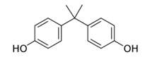 | Cytotoxic therapy | 228.0 | 3.32 |
| Caffeine | 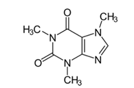 | Central Nervous System stimulant | 194.2 | 0.16 |
| Membrane | Feed Concentration (mg/L) | Rejection (%) | Ref. | ||
|---|---|---|---|---|---|
| BPA | Caffeine | BPA | Caffeine | ||
| Commercial RO (TW30–1812−100) | 50 | - | 87 | - | [4] |
| Commercial RO (CE BWRO) | 1000 | - | 74–84 | - | [11] |
| Commercial RO (BW30) | - | 10 | - | 92–95 | [7] |
| PA/TiO2 TFC | 100 | - | 99 | - | [40] |
| PA/TNT TFC | 10 | 10 | 89.05 | 97.89 | This study |
Publisher’s Note: MDPI stays neutral with regard to jurisdictional claims in published maps and institutional affiliations. |
© 2022 by the authors. Licensee MDPI, Basel, Switzerland. This article is an open access article distributed under the terms and conditions of the Creative Commons Attribution (CC BY) license (https://creativecommons.org/licenses/by/4.0/).
Share and Cite
Ahmad, N.A.; Goh, P.S.; Azman, N.; Ismail, A.F.; Hasbullah, H.; Hashim, N.; Kerisnan@Krishnan, N.D.; Yahaya, N.K.E.M.; Mohamed, A.; Mohamed Yusoff, M.A.; et al. Enhanced Removal of Endocrine-Disrupting Compounds from Wastewater Using Reverse Osmosis Membrane with Titania Nanotube-Constructed Nanochannels. Membranes 2022, 12, 958. https://doi.org/10.3390/membranes12100958
Ahmad NA, Goh PS, Azman N, Ismail AF, Hasbullah H, Hashim N, Kerisnan@Krishnan ND, Yahaya NKEM, Mohamed A, Mohamed Yusoff MA, et al. Enhanced Removal of Endocrine-Disrupting Compounds from Wastewater Using Reverse Osmosis Membrane with Titania Nanotube-Constructed Nanochannels. Membranes. 2022; 12(10):958. https://doi.org/10.3390/membranes12100958
Chicago/Turabian StyleAhmad, Nor Akalili, Pei Sean Goh, Nurfirzanah Azman, Ahmad Fauzi Ismail, Hasrinah Hasbullah, Norbaya Hashim, Nirmala Devi Kerisnan@Krishnan, Nasehir Khan E. M. Yahaya, Alias Mohamed, Muhammad Azroie Mohamed Yusoff, and et al. 2022. "Enhanced Removal of Endocrine-Disrupting Compounds from Wastewater Using Reverse Osmosis Membrane with Titania Nanotube-Constructed Nanochannels" Membranes 12, no. 10: 958. https://doi.org/10.3390/membranes12100958
APA StyleAhmad, N. A., Goh, P. S., Azman, N., Ismail, A. F., Hasbullah, H., Hashim, N., Kerisnan@Krishnan, N. D., Yahaya, N. K. E. M., Mohamed, A., Mohamed Yusoff, M. A., Karim, J., & Abdullah, N. S. (2022). Enhanced Removal of Endocrine-Disrupting Compounds from Wastewater Using Reverse Osmosis Membrane with Titania Nanotube-Constructed Nanochannels. Membranes, 12(10), 958. https://doi.org/10.3390/membranes12100958