Article

Synthesis and Characterization of Titanium Dioxide Hollow Nanofiber for Photocatalytic Degradation of Methylene Blue Dye

by
Nurul Natasha Mohammad Jafri
1,
Juhana Jaafar
1,*,
Nur Hashimah Alias
2,
Sadaki Samitsu
3,
Farhana Aziz
1,
Wan Norharyati Wan Salleh
1,
Mohd Zamri Mohd Yusop
1,
Mohd Hafiz Dzarfan Othman
1,
Mukhlis A Rahman
1,
Ahmad Fauzi Ismail
1,
Takeshi Matsuura
4 and
Arun M. Isloor
5
1
Advanced Membrane Technology Research Centre (AMTEC), School of Chemical and Energy Engineering, Faculty of Engineering, Universiti Teknologi Malaysia, 81310 UTM Johor Bahru, Johor, Malaysia
2
Department of Oil and Gas Engineering, School of Chemical Engineering, College of Engineering, Universiti Teknologi MARA, 40450 Shah Alam, Selangor, Malaysia
3
National Institute for Materials Science, 1-2-1, Sengen, Tsukuba 305-0047, Japan
4
Industrial Membrane Research Laboratory, Department of Chemical Engineering, University of Ottawa, Ottawa, ON K1N 6N5, Canada
5
Membrane and Separation Technology Laboratory, Department of Chemistry, National Institute of Technology Karnataka, Surathkal, Mangalore 575 025, India
*
Author to whom correspondence should be addressed.
Membranes 2021, 11(8), 581; https://doi.org/10.3390/membranes11080581
Submission received: 9 July 2021 / Revised: 25 July 2021 / Accepted: 27 July 2021 / Published: 30 July 2021
(This article belongs to the Section Membrane Chemistry)

Abstract

:
Environmental crisis and water contamination have led to worldwide exploration for advanced technologies for wastewater treatment, and one of them is photocatalytic degradation. A one-dimensional hollow nanofiber with enhanced photocatalytic properties is considered a promising material to be applied in the field. Therefore, we synthesized titanium dioxide hollow nanofibers (THNF) with extended surface area, light-harvesting properties and an anatase–rutile heterojunction via a template synthesis method and followed by a calcination process. The effect of calcination temperature on the formation and properties of THNF were determined and the possible mechanism of THNF formation was proposed. THNF nanofibers produced at 600 °C consisted of a mixture of 24.2% anatase and 75.8% rutile, with a specific surface area of 81.2776 m2/g. The hollow nanofibers also outperformed the other catalysts in terms of photocatalytic degradation of MB dye, at 85.5%. The optimum catalyst loading, dye concentration, pH, and H2O2 concentration were determined at 0.75 g/L, 10 ppm, pH 11, and 10 mM, respectively. The highest degradation of methylene blue dye achieved was 95.2% after 4 h of UV irradiation.

1. Introduction

Water contamination caused by domestic wastes, industrial chemicals, fertilizers, and organic dyes has become one of the global environmental concerns [1]. Organic dyes are being used in industries like leather, cosmetics, textile, and paper manufacturing. The amount of dye produced annually in the world was estimated to be a million tons [2] and the wastewater from these industries is often discharged into natural waters without being treated. The pigmented, highly hazardous, non-biodegradable, and carcinogenic dye-contaminated effluents may affect the appearance of water and cause serious diseases in humans even at a very low concentration. Thus, it is essential to develop an effective and reliable method to treat dye wastewater. Typically, conventional treatments like adsorption [3] and coagulation [4] are used in treating dye-contaminated wastewater. However, these methods do not completely destroy the pollutants but produce suspended particles or sludge that require post-treatment disposal.
In recent years, photocatalytic oxidation has been deemed a promising water purification technique. Essentially, photocatalytic oxidation involves the reaction between light-absorbing catalysts and pollutants. Photocatalytic degradation can occur within a few hours at room temperature. At the end of the process, the pollutants are mineralized to less harmful products (carbon dioxide and water) without forming secondary hazardous products. Metal oxide semiconductors like titanium dioxide, zinc oxide, silicon dioxide, and cerium dioxide [5] are often used as photocatalysts. Titanium dioxide (TiO2) is one of the most commonly used metal oxides owing to its high stability, low cost, abundance, stability, efficient photoactivity, and safety to human beings and the environment [6]. The basic principle of photocatalytic degradation needs a semiconductor whose electronic structure consists of a valence band (VB) and conduction band (CB), which are separated by a bandgap of energy. Upon the irradiation of light energy equal to or higher than the bandgap energy level, the valence electron (e) is promoted to the valence band, leaving a positive hole (h+) in the valence band. Both e and h+ are strong reducing and oxidizing agents, respectively. They react with the water molecules to produce superoxide (•O2) and hydroxyl (•OH) radicals, that attack the organic compounds, eventually converting them into harmless products of carbon dioxide and water.
Degussa P25, a commercially available TiO2, is one of the most efficient photocatalysts in terms of cost and photocatalytic ability, with a number of works published elsewhere [7,8,9,10,11]. Despite that, these studies reported some issues with this particular photocatalyst, and one of them is the high bandgap energy (~3.2 eV) The high bandgap value limits the light utilization efficiency and reduces the number of electrons that could participate in the redox reaction, which consequently deteriorates the photocatalytic activity. The photoexcited electrons that exist in a meta-stable state also have the tendency to recombine with the positive holes. Another drawback of Degussa P25 TiO2 reported is the low specific surface area (50 m2/g). The efficiency of a photocatalyst is highly dependent on its active surface area. The larger the amounts of reagents adsorbed on the surface, the higher their possibility to take part in the reaction.
A variety of strategies have been employed to enhance the photocatalytic properties of a semiconductor, including morphology control [12], doping [13], conjugation [14], and incorporation of co-catalyst [15]. The structure of semiconductors imposes a significant impact on the photocatalytic properties of a semiconductor; hence, nanostructure engineering has been acknowledged as an effective strategy. This can be proven through the application of various nanostructures photocatalytic fields such as quantum dots, nanowires, nanorods, nanofibers, and hollow nanofibers [16]. In contrast with solid one-dimensional nanostructures, hollow nanofibers are interesting to be further studied because they display desirable properties as photocatalysts, owing to their higher surface-to-volume ratio. A previous study reported that the surface area of the hollow nanofibers is twice as large as conventional nanofibers [17]. Thus, this study aims to enhance the photocatalytic properties of the TiO2 photocatalyst by synthesizing titanium dioxide hollow nanofibers (THNF) with extended surface area, maximized light adsorption ability and improved bandgap through the construction of anatase–rutile heterojunctions.
In recent years, many techniques have been reported for the fabrication of hollow nanofibers such as one-pot electrospinning [16], coaxial electrospinning [18], and self-assembly [19]. However, these methods suffer from some limitations. For example, there are limited common solvents that can be used to prepare a blend polymer solution. Moreover, it is required to find the optimum electrospinning parameters for each polymer in the blend solution. Meanwhile, for coaxial electrospinning, the core and sheath solution should be immiscible for the successful synthesis of hollow nanofibers. In the self-assembly process, the process is complex and has low throughput. The most prominent limitation of the above-mentioned technique is the inability to control the properties of the resultant structure in terms of dimensions, morphology, and crystallinity.
On the other hand, template synthesis enables the fabrication of hollow nanofibers with controlled properties. Typically, a precursor of the target material is deposited onto a sacrificial template, followed by a template elimination process [20]. Electrospun polymers are often used as the template material due to the simple preparation method, morphology flexibility, and very low cost. The morphology of the resultant product is directly influenced by the property of the template. Therefore, in this study, we proposed the preparation of TiO2 hollow nanofibers with controllable properties via template synthesis for the photocatalytic degradation of methylene blue. Polyacrylonitrile (PAN) was used as the template and the TiO2 precursor was deposited via the dip-coating method. Then, the effect of calcination temperature during the template removal on the fiber properties was determined. We also proposed the possible formation mechanism of THNF. To the best of our knowledge, the mechanistic insights of TiO2 hollow nanofiber formation via template synthesis have not been reported elsewhere. In addition, the effect of several operating parameters that are the catalyst loading, dye concentration, pH, and hydrogen peroxide concentration on the photodegradation of methylene blue (MB) dye was also investigated.

2. Materials and Methods

2.1. Materials

Polyacrylonitrile, PAN at MW = 150,000 and titanium (IV) isopropoxide, TTIP, (97% in solution) were bought from Sigma Aldrich. N,N-dimethylformamide (DMF) was bought from RCI Labscan. Meanwhile, acetic acid (glacial 100% purity) and nitric acid (65% purity) were bought from Merck. All materials were used directly without any purification.

2.2. Preparation of Nanofibers Template

PAN dope solution was prepared by dissolving 8 wt. % of PAN with DMF. The mixture was stirred at 60 °C for 24 h until homogenous. The electrospinning machine was supplied by Progene Link Sdn Bhd, Selangor, Malaysia. The prepared solution was fixed in a plastic syringe with a blunt tip stainless steel needle. A voltage of 12 kV was applied for electrospinning. The electrospinning process was conducted at the flow rate of 1.0 mL/h and 15 cm horizontal distance from the needle tip to the collector. After the electrospinning process was completed, the as-spun nanofibers were dried at 80 °C for 2 h to remove the excess moisture and solvent, followed by calcination. The oxidation process was done as follows: (i) calcination at 150 °C for 1 h (2 °C/min); (ii) calcination at 230 °C for 3 h (1 °C/min); and (iii) cooling to room temperature.

2.3. Synthesis of THNF Photocatalysts

THNF was obtained through three steps. The first one is the electrospinning of PAN nanofibers. Secondly, TiO2 sol-gel was deposited on the obtained as-spun PAN nanofibers. Lastly, TiO2/PAN nanofibers composite (TPNF) was calcined for template removal. TiO2 sol-gel was prepared by mixing 10 mL of TTIP and 10 mL acetic acid, CH3COOH. Then, 100 mL of distilled water was added to accelerate the hydrolysis reaction. A total of 1 mL of nitric acid, HNO3 was added into the mixture to achieve a pH range of 4–6. The mixture was stirred for 24 h at 60 °C until a whitish-blue solution was formed. TPNF composite was formed by dip-coating as-spun PAN nanofibers in the sol-gel at immersion and withdrawal speed of 5 mm/s. Then, the nanofibers were dried in the oven at 90 °C for 2 h before being calcined in air at 600 °C for 4 h to remove the PAN component. During the calcination process, the calcination temperature was set at 400, 500, and 600 °C for 4 h. The samples were denoted as THNF400, THNF500, and THNF600, respectively.

2.4. Characterization

The morphology of the nanofibers was observed using a field emission scanning electron microscope (FESEM, ZEISS Crossbeam 340, Jena, Germany). Thermogravimetric Analysis (TGA4000, Perkin Elmer, Shelton, CT, USA) analysis was conducted to monitor the mass of the TPNF as a function of temperature or time during the calcination. TGA was used to quantify the decomposition or the loss of the PAN nanofiber template in the formation of THNF based on the weight of the nanofiber. Phase identification of the crystalline material was done using an X-ray diffractometer (XRD, Rigaku D/Max 2200 PC, Tokyo, Japan) with CuKα radiation (λ = 1.540 Å, 40 kV and 30 mA). Nitrogen adsorption/desorption measurement was performed to examine the surface area of the nanofiber samples with an automatic gas adsorption instrument (BEL, Belsorp-max, Osaka, Japan). A UV-Vis-NIR Spectrophotometer (UV-3101PC Shimadzu, Kyoto, Japan) was used in this study to measure the optical absorption behaviors of the photocatalyst. A similar instrument was used to measure the concentration of methylene blue (MB) in the solution at 664 nm wavelength.

2.5. Photodegradation Experiment

Different concentrations of MB solution (i.e., 10, 20, 30, 40 and 50 mg/L) were prepared by dilution of the as-prepared 1000 mg/L MB stock solution. The photocatalytic degradation of MB dye using THNF photocatalysts was conducted under the illumination of a 3.0 mW/cm2 UV lamp (Vilber hourmat, λ = 312 nm, 30 watts) manufactured by Wuhan Co-shine Technology Co., Ltd., China, installed in a custom-made stainless steel photoreactor (60 × 35 × 42 cm3). The photoreactor consisted of a glass beaker, a magnetic stirrer, and the UV lamp was installed 15 cm above the beaker, as shown in Figure 1. In a typical photocatalytic degradation set-up, 0.25 g/L of THNF photocatalysts was suspended in 100 mg/L of model wastewater MB dye solution. The solution was dispersed using an ultrasonicator and oxygenated in the dark for 1 h to reach an adsorption–desorption equilibrium. At every 15 min interval, 5 mL of sample aliquot was collected to analyze the desorption percentage. After 1 h, the UV lamp was turned on while keeping the solution magnetically stirred. The sample was also collected at a regular time interval. The absorbance spectrum of the samples was measured using high-performance liquid chromatography (HPLC, Agilent Technology1200 Series). The degradation percentage was determined by Equation (1):
D e g r a d a t i o n   % = C 0 C C 0 × 100 = A 0 A A 0 × 100
where C0 and C are the MB dye concentration initially and after irradiation, respectively. A0 and A are corresponding optical absorbances for initial and after irradiation, respectively.

3. Results

3.1. TiO2 Precursor Deposition on PAN Nanofiber

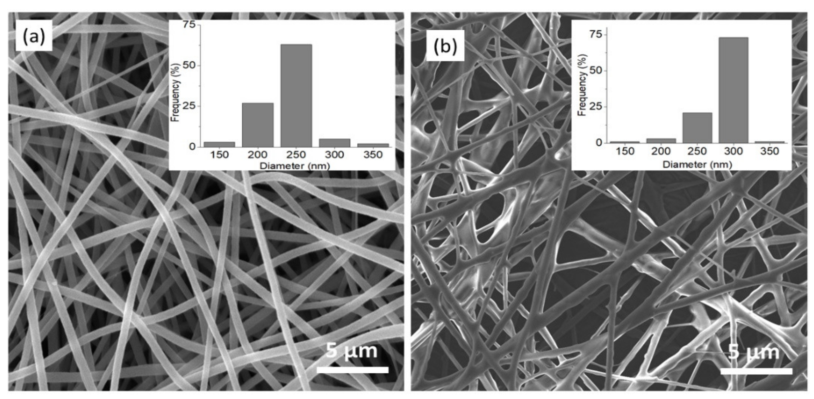
A successful synthesis of hollow nanostructures is influenced by the successful deposition of the target material precursor on the template. Morphology analysis on the PAN and TPNF was conducted using FESEM. Figure 2 shows the FESEM images and diameter distribution of the nanofibers. The electrospun PAN nanofibers have a randomly oriented, non-woven structure with a smooth surface. The average diameter of PAN nanofibers is 236 ± 16 nm. Meanwhile, the FESEM image of TPNF shows nanofibers with significantly rougher structures and larger diameters. The average diameter of TPNF is 286 ± 22 nm, as shown in the inset of Figure 2b. After the dip-coating of the TiO2 sol-gel precursor, the diameter of the nanofibers increased by about 20%. The dip-coating process had produced a uniform and conformal layer around the PAN nanofibers. The original well-defined structure and original arrangement of the PAN nanofibers are still retained after the TiO2 deposition.
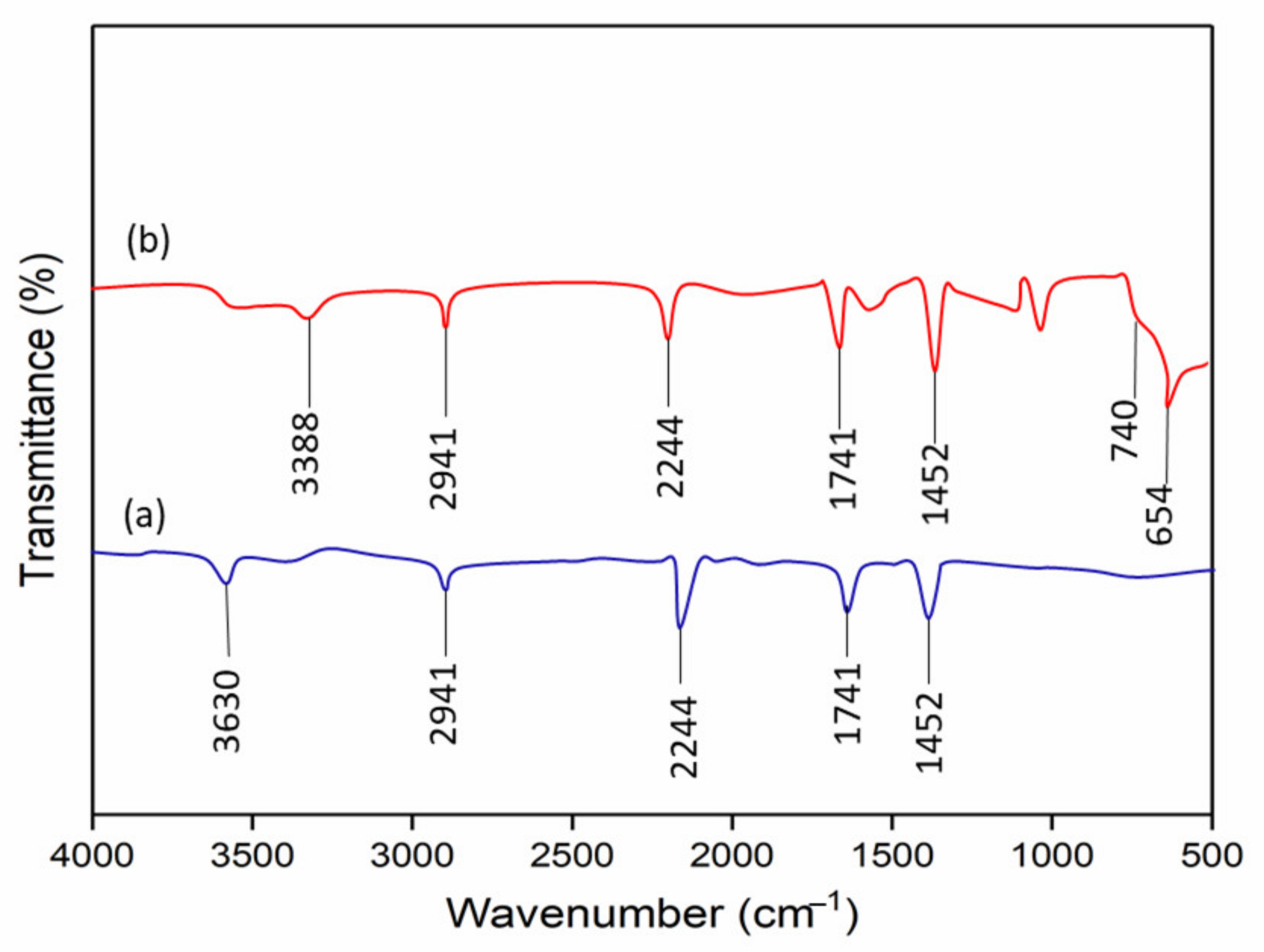
The deposition of TiO2 on PAN nanofibers was further confirmed by conducting FTIR analysis. The FTIR spectra of PAN nanofibers are shown in Figure 3a. The peaks that appeared at 3630 cm−1 can be attributed to –OH stretching vibrations. The peak at 2941 cm−1 was assigned to the stretching vibration of –CH in CH2. The peak at 2244 cm−1 was assigned to the stretching vibration of the C≡N functional group. The peak at 1741 cm−1 might originate from the stretching vibration of C=O, due to the hydrolyzed PAN or the residual DMF solvent. Meanwhile, the peak at 1452 cm−1 can be attributed to -CH bending vibration. This finding is in accordance with other published work by Zhang et al. [21]. The appearance of new peaks can be observed in the FTIR spectra of TPNF, as shown in Figure 3b. A broad peak appeared around 3000–3500 cm−1, which was believed to correspond to hydroxyl groups (–OH) in TiO2. The emerging broadband below 1000 cm−1 (740 and 654 cm−1) was ascribed to the characteristic of Ti–O and Ti–O–Ti stretching and bending vibration for TiO2. These observations confirm the successful deposition of TiO2 on the PAN template and imply that PAN is a compatible material to be used as the template in THNF synthesis.
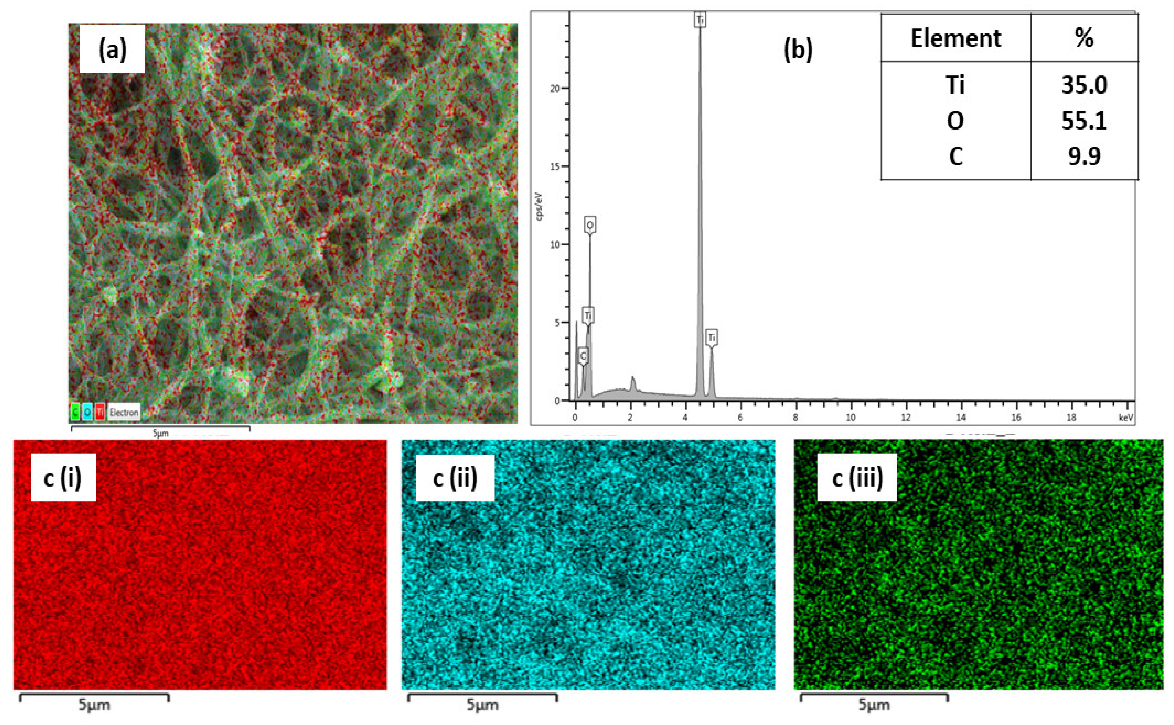
Elemental analysis was also carried out to confirm the successful deposition of the TiO2 layer onto the PAN nanofibers. The composite nanofibers consisted of titanium (Ti), oxygen (O), and carbon (C) elements with an elemental percentage of 35.0%, 55.1%, and 9.9%, respectively. The EDX mapping in Figure 4a shows that Ti (red dots) was present uniformly on the nanofibers. This was confirmed by the EDX spectrum in Figure 4b, which shows that Ti and O were present in large quantities, while C was in a lower quantity. The relatively low percentage of C indicates that the majority of the surface of PAN nanofibers was covered with the TiO2 sol-gel. This result confirms the successful deposition of TiO2 on PAN nanofibers.

3.2. Effect of Calcination Temperature

3.2.1. Thermal Decomposition Analysis

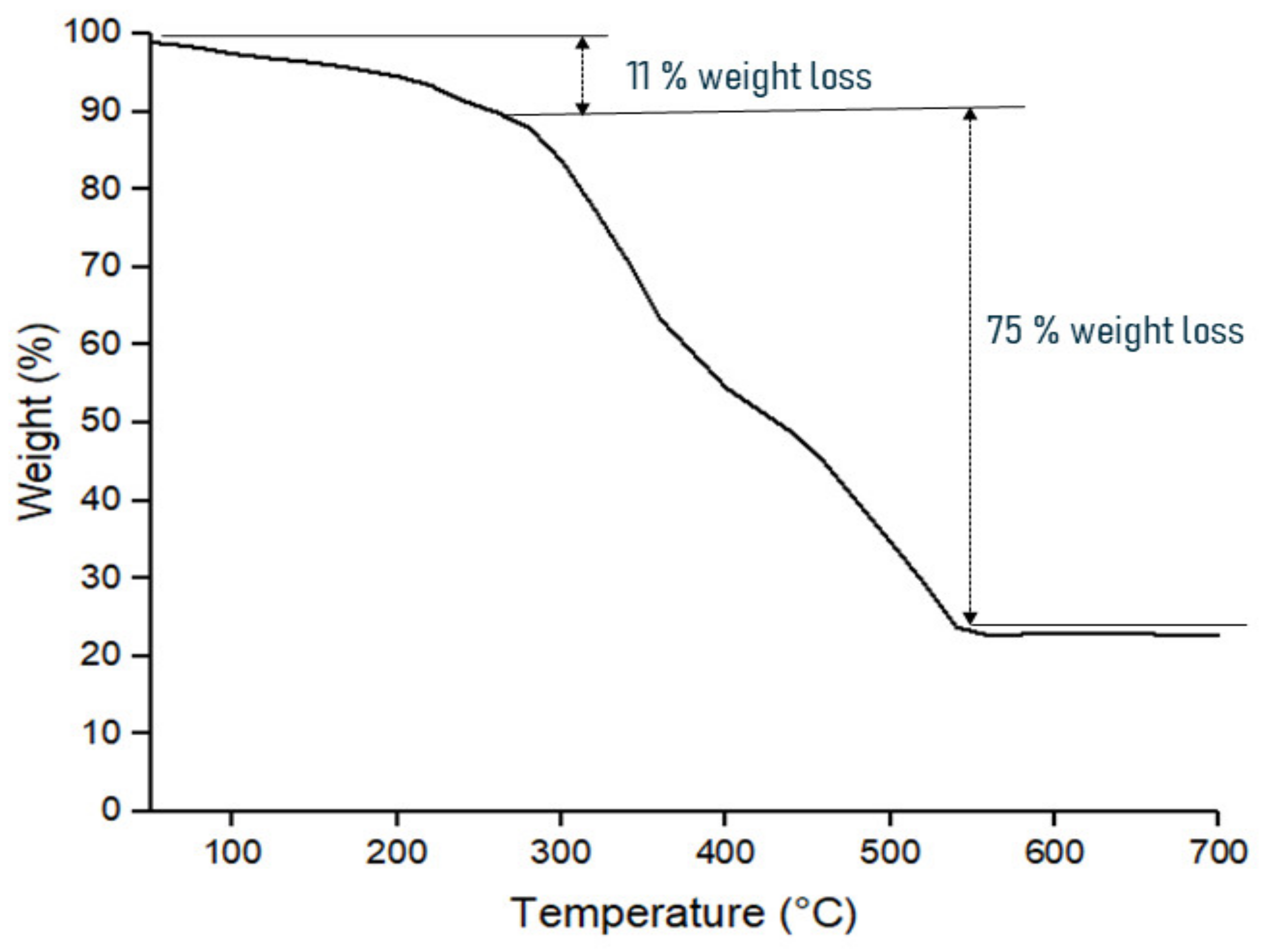
TPNF was calcined at a high temperature between 400 to 600 °C to obtain THNF. The effect of temperature on the decomposition of TPNF was analyzed by using thermogravimetric analysis (TGA). The curve of weight loss percentage against temperature is presented in Figure 5. It can be observed that the decomposition of TPNF occurred in three stages. From the starting of the heating process up to 280 °C, the weight of the nanofibers slowly decreases by about 11%. This behavior is associated with the loss of moisture in hydrous TiO2 and the evaporation of DMF solvent. From 280 to 540 °C, the nanofibers undergo rapid weight loss by about 77% from the original weight of TPNF. The weight loss is due to the breaking of the C-C bond and decomposition of the PAN component. A previous study confirmed that the melting point of polyacrylonitrile is 317 °C, and it decomposes beyond that [22]. Through mass spectrometry analysis, absolute confirmation of the decomposition is made by identifying the gaseous products as they evolved. Hydrogen cyanide (HCN) was identified as the predominant product, while ammonia (NH3) existed in a smaller quantity. Finally, a stagnant weight of TPNF is observed beyond 540 °C, indicating that the PAN template has been removed completely. These findings are similar to the TGA analysis by Gao et al. [23] for the decomposition of PVA nanofibers. Therefore, the total weight loss of TPNF was about 86% from its original weight. These findings indicated that THNF is successfully formed at a temperature of 600 °C.

3.2.2. Morphological Analysis

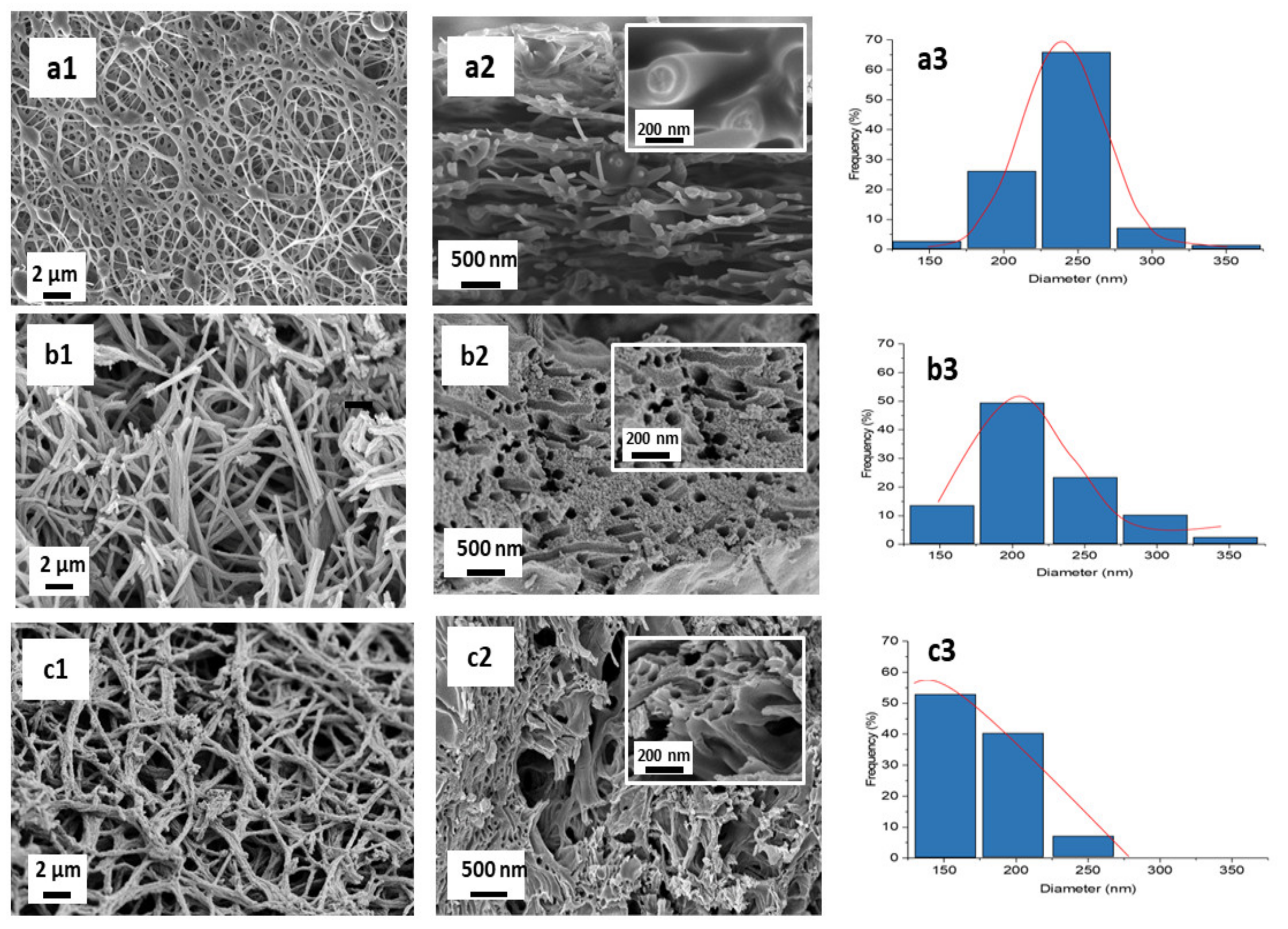
Figure 6(a1) shows the FESEM images of THNF400 at 5k magnification. The nanofibers have a wriggly and irregular surface. The nanofibers calcined at 400 °C have good interconnectivity with each other. Figure 6(a2) shows the cross-sectional FESEM image of the nanofibers at 10k magnification. In the figure inset of Figure 6(a2), the boundary between the inner and outer sections is visible. However, no hollow structured nanofibers can be observed at this temperature. The average nanofiber diameter is 236 ± 34 nm, as shown in Figure 6(a3). These observations imply that at 400 °C, PAN nanofibers had melted and decomposed, corresponding to the TGA curve in Figure 6. Meanwhile, TiO2 nanoparticles around the PAN nanofibers had also been formed. However, the appearance of TiO2 was not obvious, possibly because of the melted PAN nanofibers that covered the surface of the nanofibers. The agglomeration of melted PAN nanofibers and the formed TiO2 nanoparticles is a possible explanation for the wriggly and irregular surface of the nanofibers. The synthesis of titanium dioxide hollow nanofibers was not successful at 400 °C because it was not sufficient to completely burn off PAN nanofibers. Hence, the calcination temperature was increased to 500 °C.
Figure 6(b1) reveals THNF500 with a rougher surface and shorter length relative to THNF400, with an average diameter of 240 ± 39 nm. Referring to the TGA curve in Figure 5, at 500 °C, the weight of the nanofibers remains unchanged, which implies that most of the PAN components had been removed. The disappearance of PAN reveals the TiO2 nanoparticles surrounding the nanofibers. The rougher surface is attributed to the promoted growth of crystalline TiO2 grain as the temperature increased. The heat effect also causes a decrease in nanofiber length. Figure 6(b2) shows the appearance of hollow cavities at the nanofibers cross-section, with agglomerated nanofibers strands.
The formation of THNF was studied at the temperature of 600 °C. Figure 6(c1) shows the FESEM image of THNF600 at 5k magnification. In comparison to THNF500, the surface of THNF600 was prominently rougher, due to the highly crystalline properties caused by the increasing calcination temperature. The average diameter of THNF600 was 177 ± 32 nm. The decrease in diameter can be attributed to the shrinkage of nanofibers during the heating process. In Figure 6(c2), hollow cavities at the nanofibers core can be observed. Therefore, it can be deduced that the formation of TiO2 hollow nanofibers is highly dependent on the decomposition of PAN and the formation of TiO2 nanoparticles on the shell side of the PAN fibers, which are influenced by the increase in the calcination temperature.

3.2.3. Nitrogen-Desorption Analysis

Degussa P25 is a commercially available titanium dioxide photocatalyst that is widely used, attributed to its high level of photocatalytic activity. However, one of the remaining issues of this type of photocatalyst is its low specific surface area (SBET), which is about 50 m2/g. Hence, with the synthesis of hollow-structured TiO2 nanofibers, we aimed to further enhance the specific surface area of the catalyst. The specific surface area and porosity of THNF400, THNF500, and THNF600 were quantified using nitrogen adsorption–desorption by applying the Brunauer, Emmett, and Teller (BET) theory.
The BET surface area of each sample is tabulated in Table 1. THNF400 is observed to have an SBET of only 13.3216 m2/g. This value is significantly lower than that of Degussa P25. Meanwhile, the specific pore volume of THNF400 was 0.06354 cm3/g. In reference to Figure 6, at 400 °C, the majority of the PAN component still existed in the nanofibers. Therefore, the low surface area and pore volume of THNF400 could possibly be caused by the melting of the PAN component that covered and clogged the existing pores on the surface of the nanofibers. This statement is corroborated by the FESEM image of THNF400 in Figure 6. On the other hand, relatively higher SBET and specific pore volume were recorded by THNF500, which was 43.4085 m2/g and 0.2349 cm3/g, respectively. The increased value is possibly due to the almost completed PAN decomposition at 500 °C, which led to the appearance of hollow cavities and the revelation of the rougher structure of the nanofibers. With the increasing calcination temperature, the effect of heat produces more crystalline TiO2 with more prominent grains. In the presence of hollow cavities and rough surfaces, there was a higher available surface for nitrogen adsorption. THNF600 possessed the highest SBET and specific pore volume, which were 81.2776 m2/g and 0.32716 cm3/g, respectively. Based on the morphology and average diameter of THNF600, the increase of SBET and specific pore volume can be attributed to the hollow structure and smaller diameter of the nanofibers. Hollow-structured nanofibers consist of outer walls and empty spaces inside a distinct shell. The abundance of reactive sites increases the area for nitrogen adsorption. This phenomenon is in line with a previous study that stated that the surface area for hollow copper oxide particles is larger than the solid particles of corresponding material [24]. Meanwhile, the relatively smaller diameter of THNF600 gives it a higher surface area-to-volume ratio. The smaller the diameter of the nanofibers, the larger the adsorption area per unit volume. This property gives THNF600 the upper hand in photocatalytic reactions.

3.2.4. Crystallinity Analysis

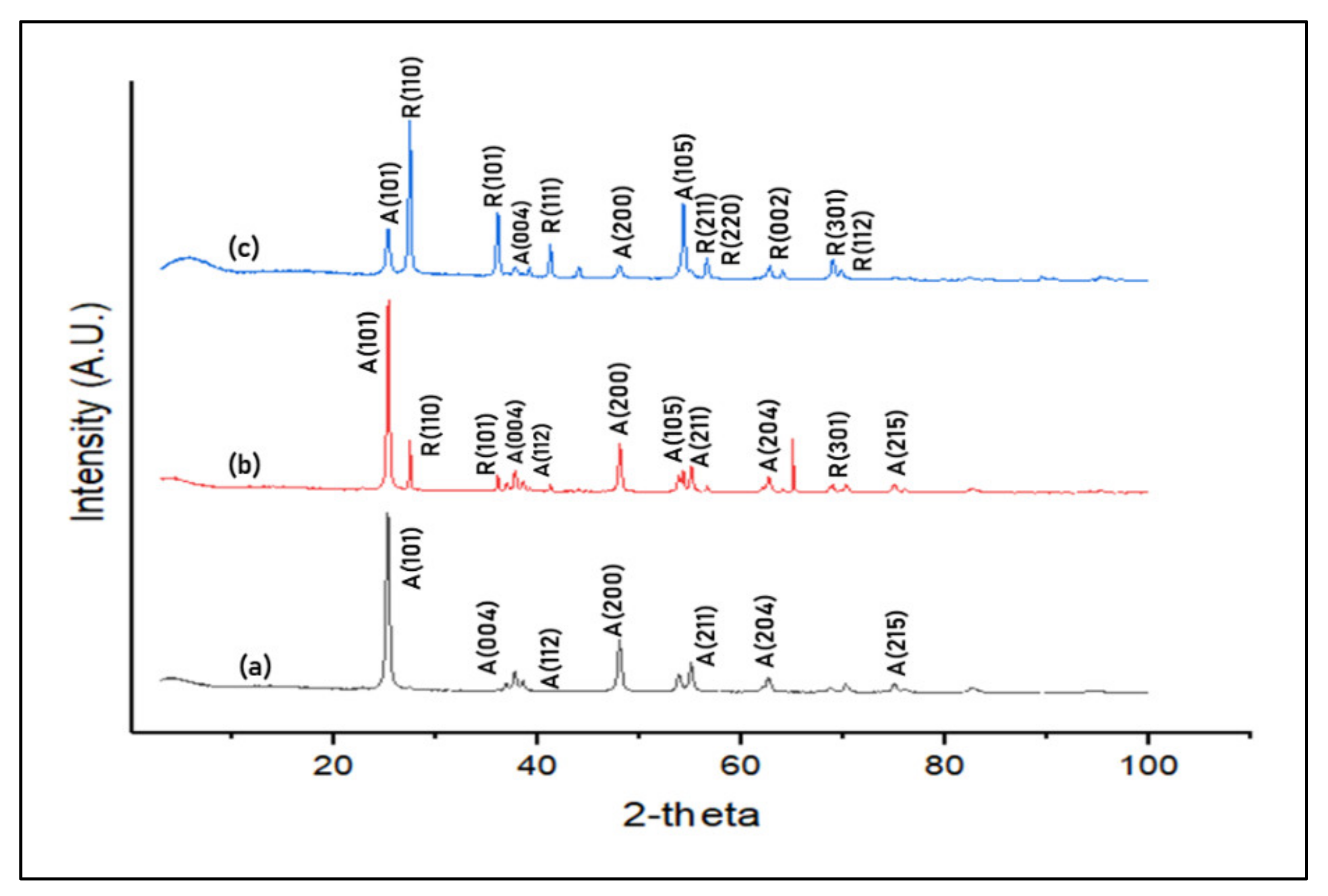
The identification of the phases that exist in THNF400, THNF500, and THNF600 was conducted using X-ray diffraction (XRD). Based on the XRD patterns presented in Figure 7, it can be deduced that all samples are crystalline. From XRD spectra (a), the peaks of THNF400 are identified at 2Ɵ = 25.3°, 37.7°, 41.2°, 48.0°, 55.0°, 62.7°, and 75.0°, which correspond to (101), (004), (112), (200), (211), (204), and (215) crystal planes. Based on JCPDS card no. 21-1272, all the diffraction peaks are well-defined and can be assigned to the anatase TiO2. Since there are no other peaks associated with other crystalline forms were detected, this indicates that THNF400 was purely anatase.
The transformation of the anatase to rutile phase can be seen in Figure 7, XRD spectra (b). A mixture of anatase and rutile diffraction peaks can be observed in THNF500. Rutile TiO2 begins to form with the emerging of relatively weak rutile diffraction peaks at 2Ɵ = 27.4°, 36.0°, and 68.7°. These peaks correspond to (110), (101), (301) planes based on JCPDS card no. 21-1276. Meanwhile, the other peaks are (101), (004), (112), (200), (105), (211), (204) and (215), which existed at 2Ɵ = 25.3°, 37.7°, 41.2°, 48.0°, 53.7°, 55.0°, 62.7° and 75.0°. Upon calculation, THNF500 consisted of 82.1% anatase and 17.9% rutile TiO2.
Meanwhile, further crystallization is observed in THNF600, XRD spectra (c), which is comprised of 24.2% anatase and 75.8% rutile. Additional rutile peaks begin to emerge at 2Ɵ = 41.2°, 56.6°, 56.8°, 62.8° and 69.7°, which corresponds to the planes (111), (211), (220), (002), and (112). The existing rutile peaks of (110), (101), (301) planes had increased in sharpness and intensity.
From the XRD result, it can be concluded that the phase conversion from anatase to rutile is highly influenced by the calcination temperature. Upon heat treatment, the octahedral TiO2 undergoes distortion, in which the breaking and reforming of new Ti-O bonds takes place at the grain interface and interior. The bond breaking and lattice distortion resulted in oxygen vacancies. The oxygen vacancies serve as a nucleation site that facilitated the formation of the rutile phase [25].
The Scherrer equation was employed to estimate the crystallite size of the photocatalysts [26]. The crystallite size of THNF increased from 15.67, 21.45 to 30.03 nm as the calcination temperature increased. Higher calcination temperature had reduced the activation energy, thus promoting the crystal growth rate [27]. It was commonly known that the surface area is inversely proportional to the crystallite size because there is a greater proportion of crystals and more area to occupy [28]. However, in this study, THNF400, which had the smallest crystallite size, possessed a BET surface area of only 0.06354 m2/g, which was relatively low compared to those of THNF500 and THNF600. This phenomenon could be explained by the physical structure of the nanofibers itself, as observed in Figure 6. Despite having a larger crystallite size, THNF600 had a larger BET surface area due to the comparatively rougher structure, the presence of hollow cavities, and less agglomerated nanofiber strands. These enhanced surface properties help for better catalytic effects to speed up the surface reactions between different adsorbed reactants species and TiO2 catalysts.

3.2.5. Optical Absorbance Analysis

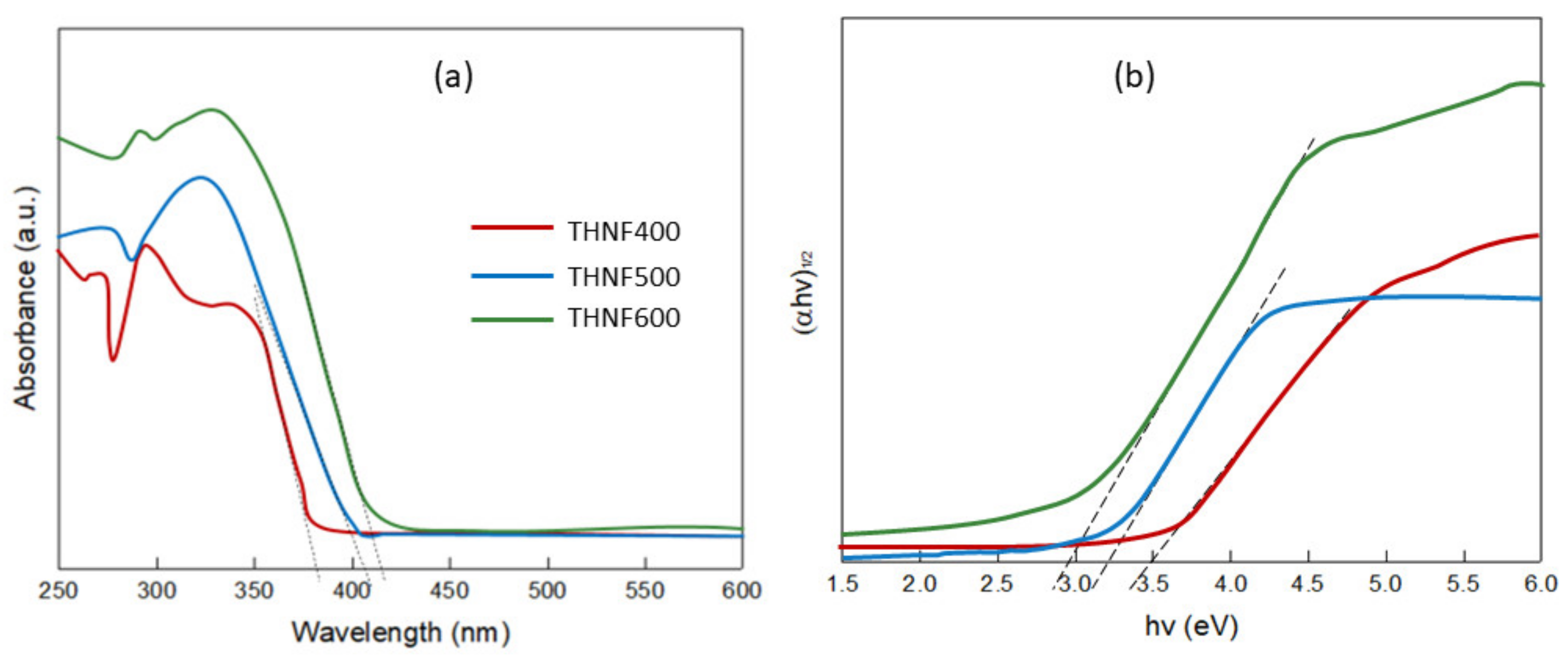
The optical properties of the photocatalysts were evaluated using a UV-Vis spectrophotometer. The UV-Vis spectrum of THNF400, THNF500, and THNF600 is shown in Figure 8a. The absorption edges of THNF400, THNF500, and THNF600 were located at about 381, 403, and 422 nm, respectively. THNF400 showed an absorbance stopping edge in the UV region (<400 nm). The absorption band at 381 nm can be assigned to the bandgap excitation of anatase TiO2 that corresponds to the band-to-band transition from the Ti 3d level to O 2p levels [29]. At a higher calcination temperature, there was a noticeable “redshift”, as indicated by the presence of shoulder in the spectra of THNF500 and THNF600 near the visible region. The enhancement in the absorption is possibly due to the presence of rutile content that intrinsically has a smaller bandgap in comparison to the pristine anatase phase [30].
The bandgap energy of the photocatalysts was estimated using the Kubelka–Munk function. A graph of (αhν)1/2 against the energy of absorbed light (eV) was plotted, as shown in Figure 8b. The bandgap energy was found to decrease from 3.50, 3.24, and 3.00 eV as the calcination temperature increased. These results indicate that THNF600 has better optical properties than THNF400 and THNF500.
It is generally known that rutile TiO2 has a narrower bandgap in comparison to anatase due to its structural properties. TiO2 consists of Ti4+ surrounded by six oxygen ions forming TiO62−. The effect of heat during calcining had altered the arrangement of ions in the TiO2 nanoparticles, thus increasing the fraction of rutile in the catalysts. As the Ti-Ti distance in rutile is shorter than in anatase, the rutile TiO2 is 9% denser. Therefore, this has caused more pronounced orbital localization of the Ti 3d and O 2p and resulted in a narrower bandgap [31]. In accordance with the XRD patterns in Figure 7, the bandgap narrowing was attributed to the higher crystallinity of THNF600, in which the majority of the fraction was rutile (75.8%). The mixed-phase photocatalysts had created heterojunction between the interface of the anatase and rutile phase. The heterojunction between the two phases accelerates the electron and hole separation due to the difference in the bandgap energy of the two phases. This phenomenon causes a difference in electric potential, which creates a strong electric field to accelerate electron and hole separation.

3.2.6. Photocatalytic Degradation of MB Dye

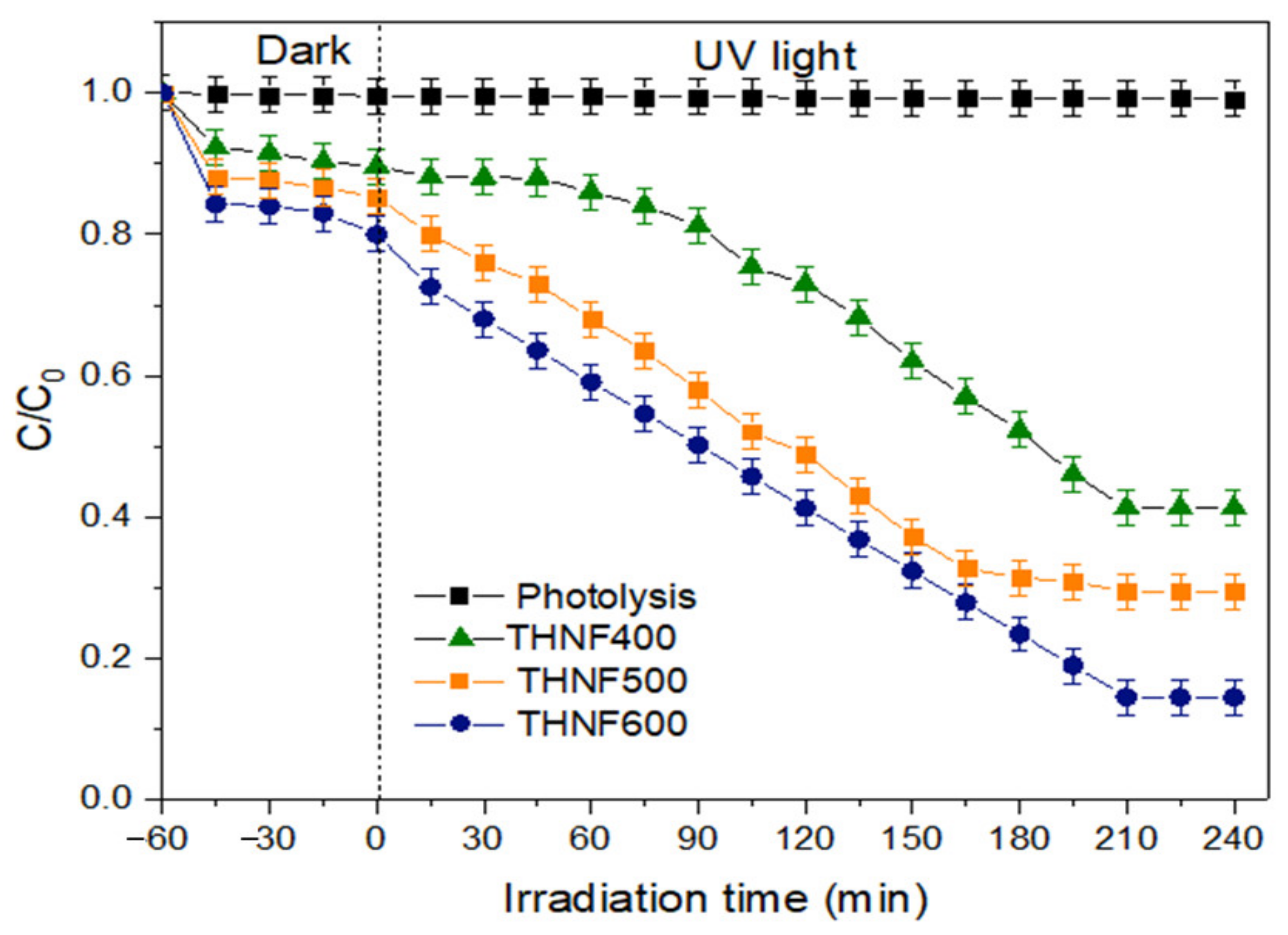
Figure 9 demonstrates MB dye degradation in an aqueous solution from the photocatalytic degradation test using THNF400, THNF500, and THNF600 photocatalysts as a function of irradiation time. The photocatalytic activity of the prepared catalysts was measured by the concentration of MB dye. The photolysis experiment using no catalysts was also set up as a control.
The degradation process was run for 5 h, including 1 h of the adsorption process in the dark. In the photolysis process, the degradation of MB dye was not significant (<5%). The degradation percentage of MB dye using THNF400, THNF500, and THNF600 was 42.9%, 61.7%, and 85.5%, respectively. Therefore, it can be deduced that the degradation of MB dye is subjected to the presence of a photocatalyst.
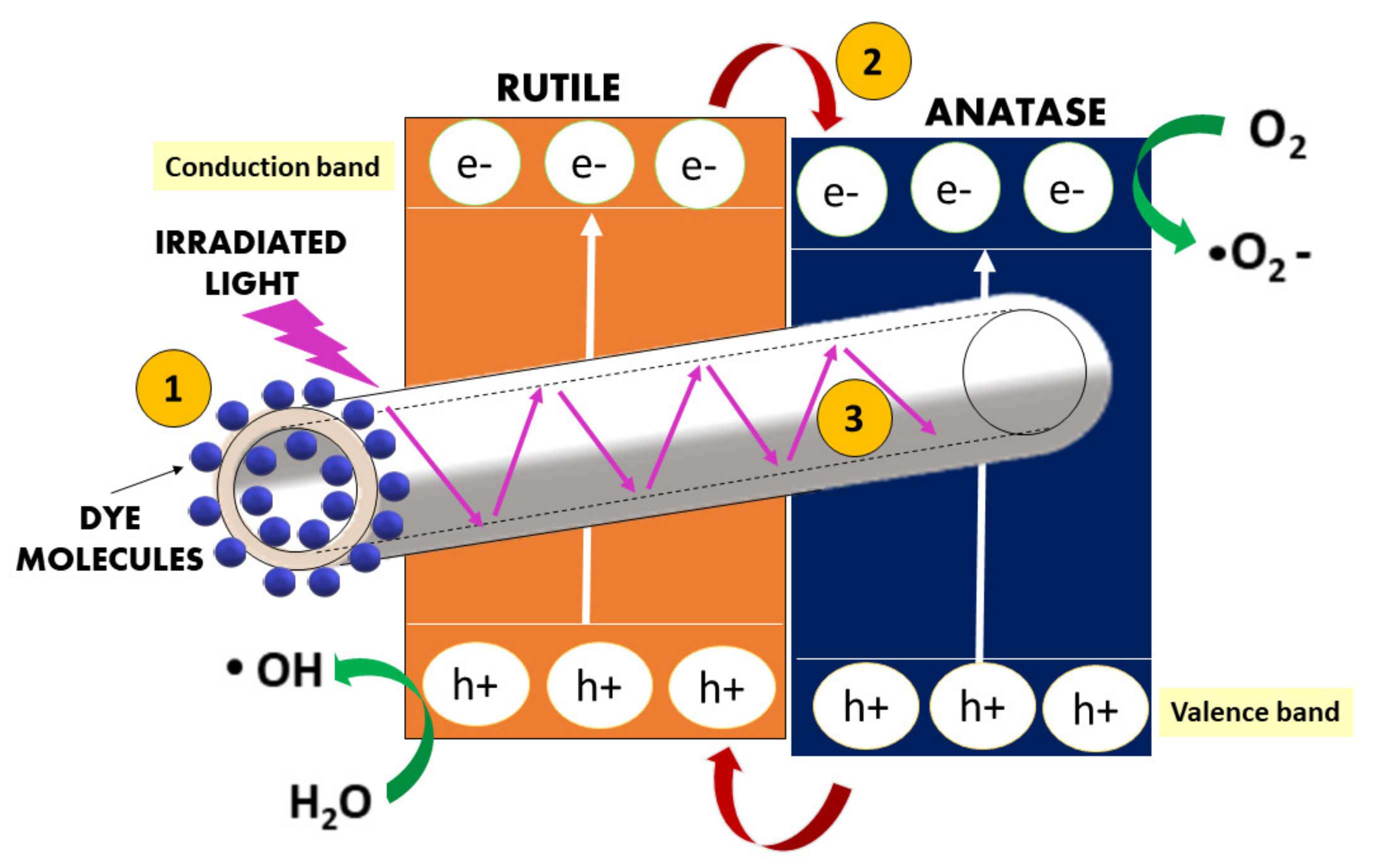
The photocatalytic performance of THNF600 has significantly outperformed THNF400 and THNF500. With regard to the analysis of photocatalysts properties, the excellent performance of THNF600 can be ascribed to: (i) the extended surface area for UV irradiation and pollutant molecule adsorption; (ii) accelerated electron-hole separation due to heterojunctions between the anatase and rutile phase; and (iii) efficient light utilization due to light scattering effect in hollow nanofibers, as illustrated in Figure 10.
THNF600 is made up of rough-surfaced nanofibers with hollow cavities. These had caused THNF600 to possess a larger surface area, in accordance with the SBET result. Generally, the degradation of pollutants occurs on the surface of the photocatalysts, so photocatalysts with larger adsorption sites are more favorable for the particular reaction. The large accessible surface area of THNF600 allows a higher amount of MB dye molecules to be diffused towards the THNF surface and consequently adsorbed at the active sites within the inner and outer spaces of the hollow nanofibers. The larger surface area of THNF600 also provided more active sites for UV illumination, resulting in higher production of •OH radicals. Besides, the hollow nanofiber structure of THNF600 had also improved the degradation process in terms of charge separation efficiency. The presence of shells and hollow cavities within THNF600 had reduced the migration distance of the photoexcited electron, which suppressed the electron-hole recombination.
Apart from that, hollow-structured photocatalysts have better light scattering effect as compared to dense photocatalyst nanofiber. Photocatalyst nanofiber with a regular dense structure tends to strongly reflect light, so light can only be adsorbed within the scale of the particle size. This leads to poor light utilization. In a hollow structure, as light penetrates the shell of the catalysts, the incident light is scattered strongly within the interior of nanofiber. The secondary light adsorption enhanced the light-harvesting properties of the catalyst. The light scattering effect had contributed to the efficient utilization of photogenerated charge carriers, thus increasing the photodegradation of MB dye using THNF600.
As can be seen from the UV-Vis absorption spectrum (Figure 8), the bandgap of THNF600 that is lower than those of THNF400 and THNF500 also contributes to the higher photocatalytic performance. The narrow bandgap had eased the transfer of electrons from VB to CB. This remarkable bandgap narrowing is attributed to the synergistic effect of the anatase and rutile phase presented in THNF600. In mixed-phase photocatalysts, heterojunction between the two crystalline lattices was created, resulting in efficient electron-hole separation. Therefore, based on the performance of different catalysts, THNF600 was used for the next experiments.
(a)
Effect of photocatalyst loading
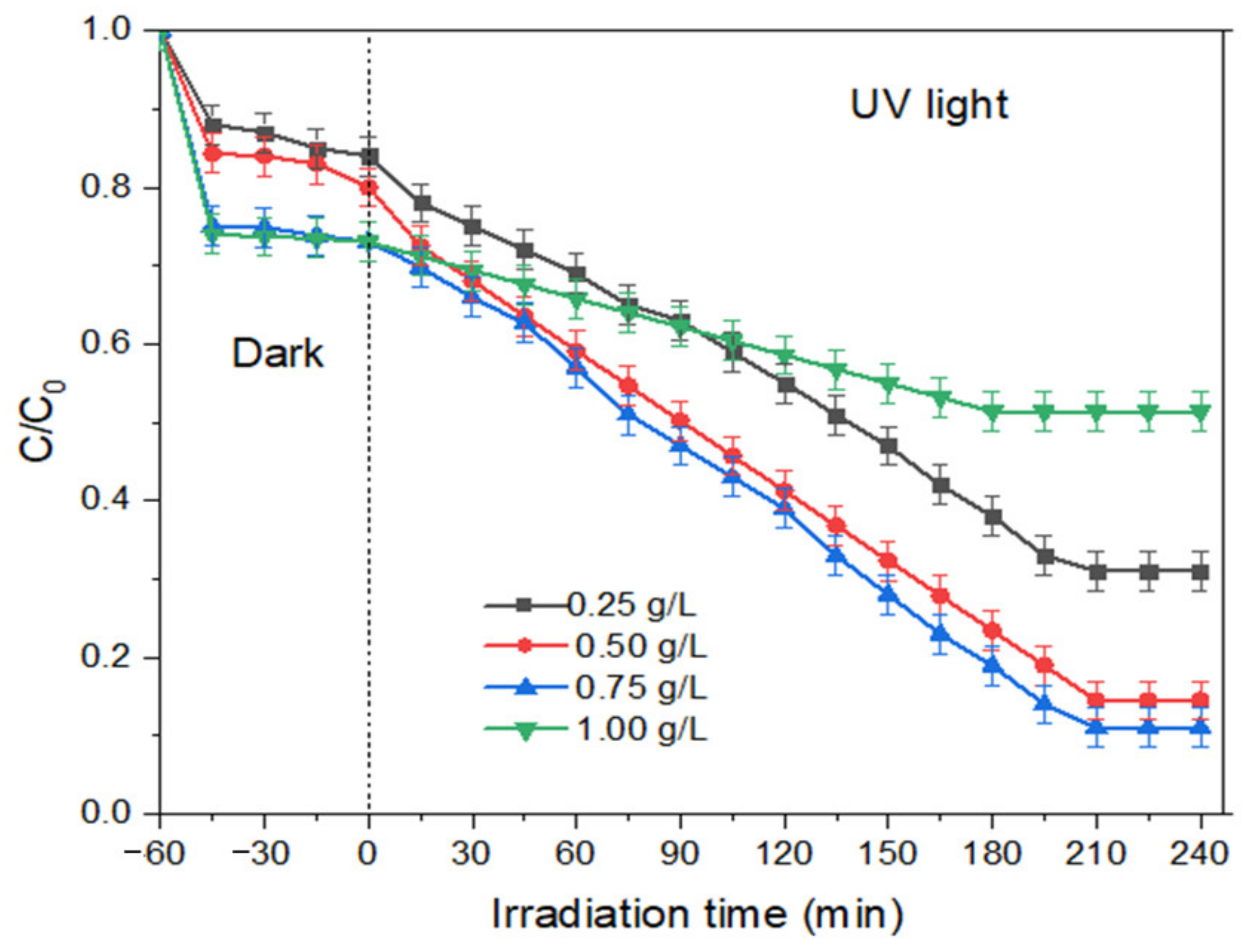
The determination of optimum photocatalyst dosage is essential because it affects the economics of the process, especially in the scaling-up process of the reaction. Other than that, the amount of catalyst used is also significant in the downstream processing, where the catalyst needs to be separated from the reaction medium. For the degradation of MB dye using THNF, the dosage of photocatalysts was studied in between the range of 0.25 to 1.0 g/L. Meanwhile, the MB dye concentration and pH were kept constant at 10 ppm and pH 7. As can be observed in Figure 11, the efficiency of MB dye degradation increases with increasing photocatalyst loading. The highest degradation percentage was obtained with 0.75 g/L THNF600, which is 85.5%. In the presence of more photocatalyst, the active sites of catalyst are higher, which increases the amounts of photons adsorbed as well as the chances for hydroxyl radical production, allowing a higher number of MB dye molecules to be mineralized. However, the degradation efficiency decreases to 49% at 1.0 g/L catalyst loading. This phenomenon is possibly caused by the interception of light in the presence of a high amount of suspended catalyst. This is also in agreement with the previous work for the degradation of phenol using N,S co-doped TiO2 under visible light irradiation [32].
(b)
Effect of dye concentration
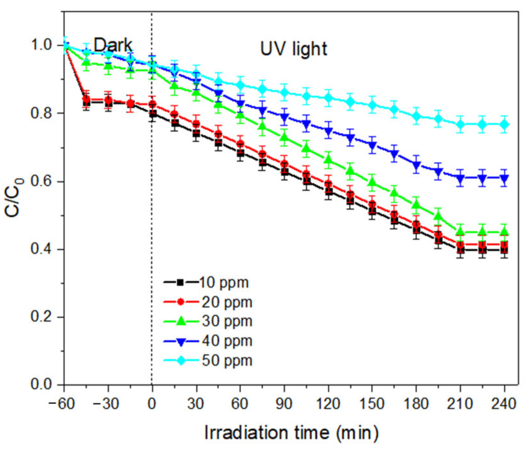
The determination of optimum initial BPA concentration is important to overcome the mass transfer deterrent force between the liquid and solid phases. In this study, the impact of increasing initial MB dye concentration was studied within the range of 10 to 50 ppm. The effect of initial BPA concentration on degradation efficiency is presented in Figure 12. A significant reduction of degradation efficiency can be observed as the MB dye concentration increases. When the concentration of pollutants increases, more of the pollutant molecules are adsorbed on the surface of the photocatalysts. Hence, this had caused the accumulation of pollutants and competition for active sites. The irradiated UV is mostly adsorbed by the pollutant molecules instead of the catalysts, resulting in lower production of ·OH radicals. Therefore, with an increasing concentration of MB dye, the number of free radicals attacking the MB dye molecules decreases. We can agree that with increasing concentration of MB dye, a higher amount of catalyst loading is required [33].
(c)
Effect of pH of the solution
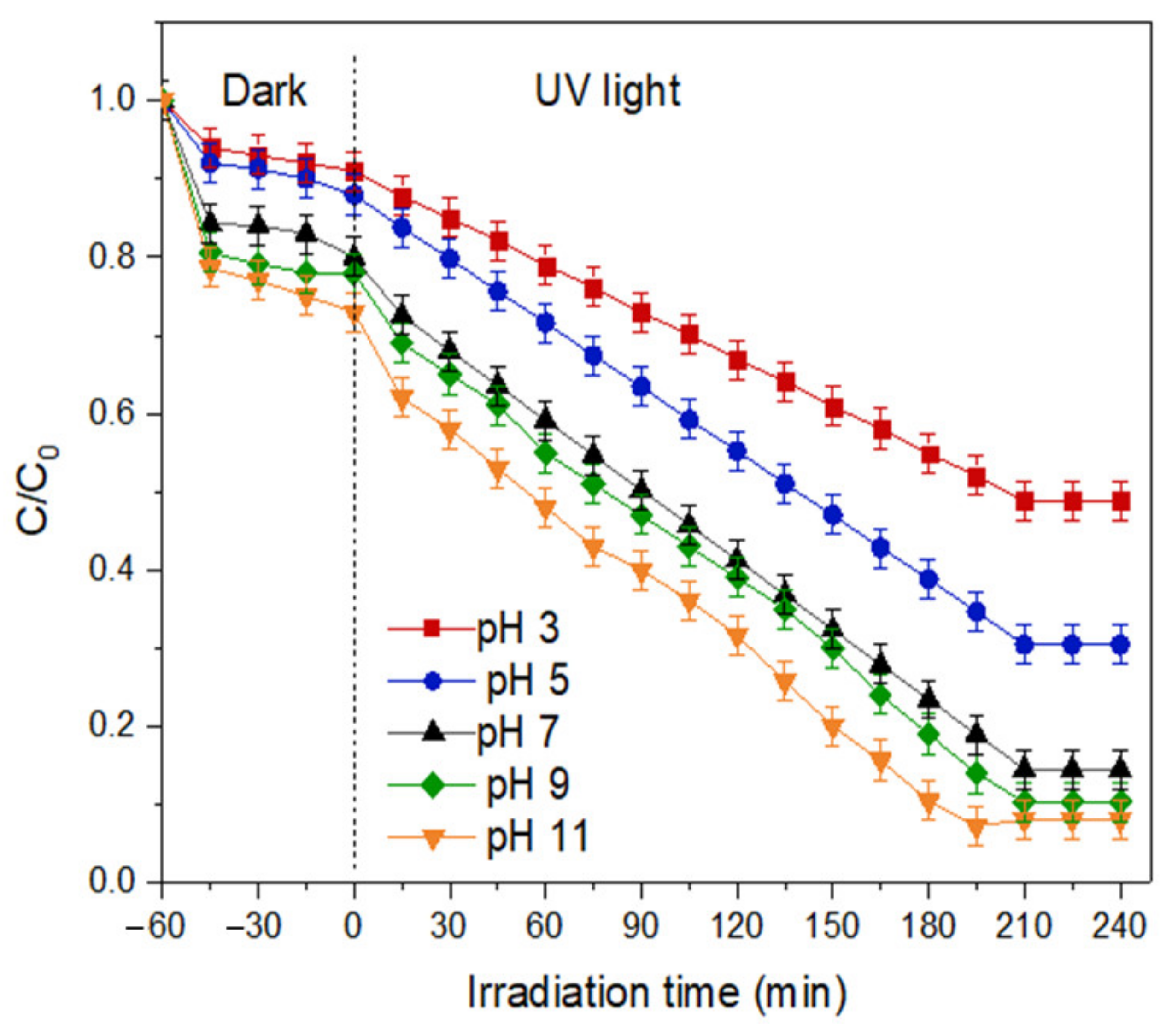
The degradation of MB dye using THNF600 catalysts was examined in the pH range of 3 to 11. NaOH and HCl were used to adjust the pH accordingly. The results in Figure 13 show that the highest degradation of MB dye occurs at pH 11. The change in pH of the solution affected the surface charge of a photocatalyst material due to the ionization of titania, as shown in Equations (2) and (3).
TiOH + H+ → TiOH2+
TiOH + OH → TiO + H2O
In acidic conditions, TiO2 is protonated upon receiving H+ from the medium, therefore it is positively charged. Meanwhile, in the basic medium, TiO2 is deprotonated, making it negatively charged [34]. Due to the Coulombic force between the cationic MB dye molecules and the positively charged THNF600 surface, repulsion between the molecules and photocatalysts occurs at low pH, hence a lower degradation percentage is expected. On the other hand, at higher pH, the cationic MB dye molecules are attracted to the negatively charged THNF600 surface, causing a better degradation percentage. The corresponding results can be seen in the previous study for the degradation of MB dye [35].
(d)
Effect of hydrogen peroxide concentration
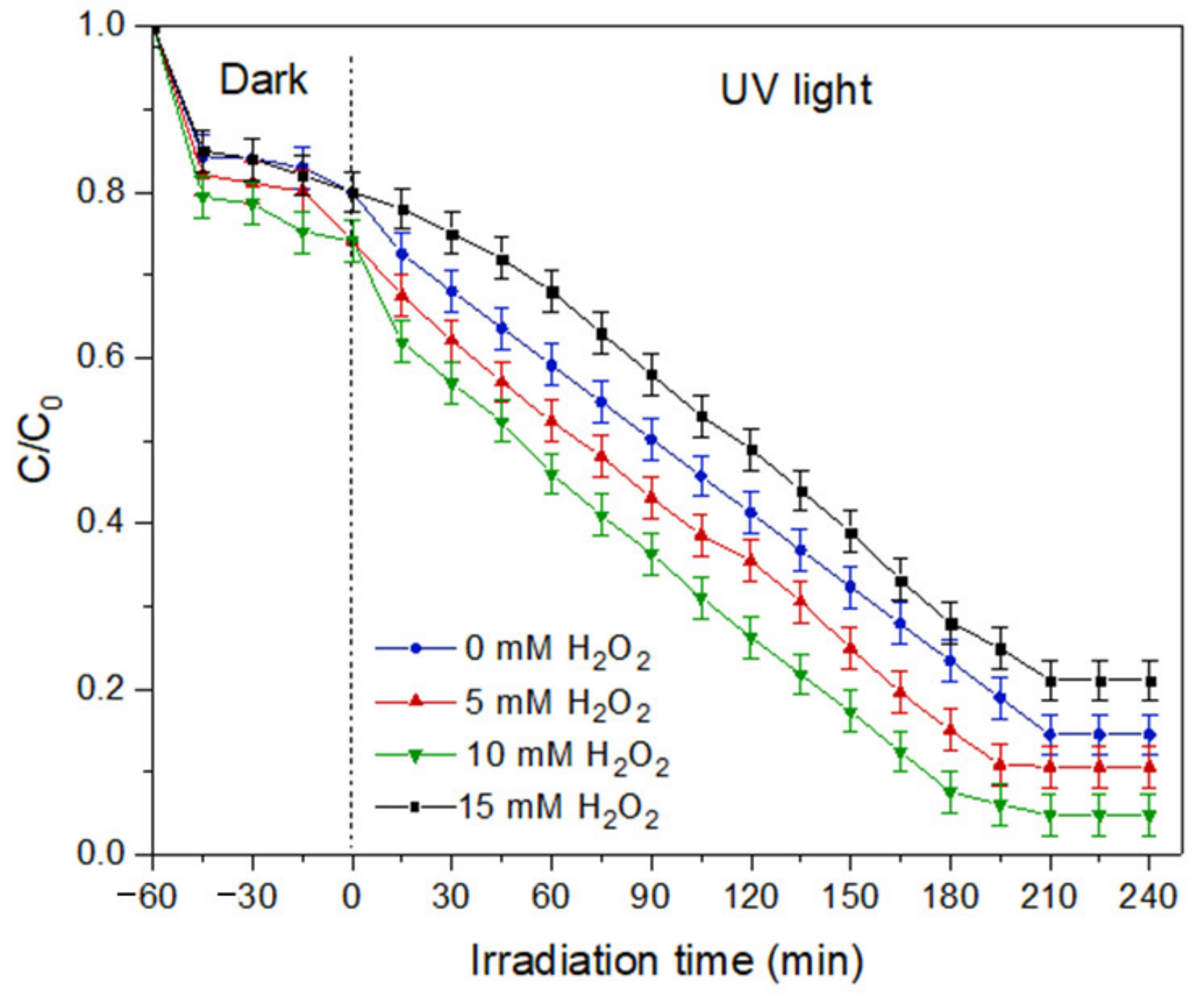
The effect of hydrogen peroxide concentration in the solution was investigated by using 5, 10, and 15 mM of H2O2. At low H2O2 concentration, the degradation of MB achieved 89.35%, as portrayed in Figure 14. The addition of H2O2 to 10 mM can improve the degradation percentage to 95.2% by increasing the production of hydroxyl radicals. Upon the irradiation of light energy, the O-O bonds in the H2O2 are broken and create active radicals that are used to mineralize the MB dye molecules. However, the result shows decreasing MB dye degradation with 15 mM H2O2. A high concentration of H2O2 performs as an electron scavenger. The excessive amount of H2O2 tends to react with the hydroxyl radicals, causing competition with the pollutant molecules to be mineralized, as has been reported previously [36].

3.3. Proposed Mechanism of Hollow Nanofibers Formation

The fabrication of hollow nanofibers using the template synthesis technique is based on the successful deposition of target material on the template and also the elimination of the template. In this study, the PAN nanofiber template was coated with TiO2 sol-gel. Essentially, sol-gel is commonly used to synthesize nanoparticles in the presence of the precursor alkoxides. An acid or a base is usually added to assist the hydrolyzation of the precursor. Nanoparticle formation from the alkoxides involve hydrolysis, condensation, further condensation, and is followed by the growth of nanoparticles. Meanwhile, the elimination of the template is done through physical and chemical approaches, including calcination, dissolution, and etching. It is crucial to study how the calcination temperature affects the formation of THNF. Apart from removing the PAN via decomposition under high temperatures, the calcination process also affected the physicochemical properties of the THNF, as discussed in the previous section.
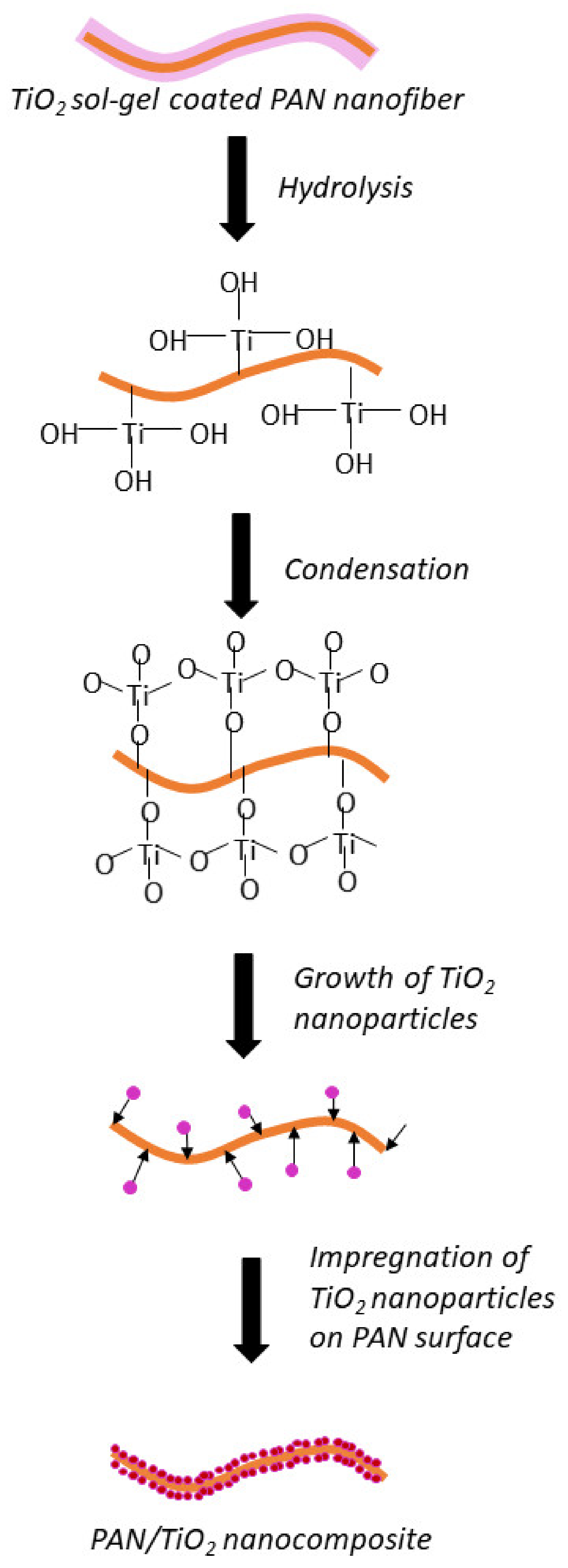
Generally, TiO2 is prepared by hydrolysis and condensation of titanium alkoxides, Ti(OR)n. Particularly in this study, titanium isopropoxide Ti[OCH(CH₃)₂]4 was used as the precursor. A hydrolysis reaction occurs when the Ti-OR group is substituted with water to Ti-OH moieties, as presented in Equation (4). Then, the condensation process forms Ti-O-Ti or Ti-OH-Ti oxide networks, as shown in Equation (5). Nucleation and growth of TiO2 particles occur when the oxide network undergoes further condensation, as shown in Equation (6). Since the TiO2 sol-gel has been successfully coated on the PAN nanofibers, the obtained TiO2 nanoparticles impregnate the surface of PAN nanofibers, forming a TPNF nanocomposite. The overall reaction is shown in Equation (7). The mechanism of TiO2 nanoparticle growth on the PAN surface is illustrated in Figure 15.
Hydrolysis of TTIP:
Ti[OCH(CH3)2]4 + 4H2O → Ti(OH)4 + 4[CH(CH3)2OH]
Condensation of Ti(OH)4:
2[Ti(OH)4] → Ti(OH)3-O-Ti(OH)3
Further condensation:
Ti(OH)3-O-Ti(OH)3 → 2TiO2 + 3H2O
Overall reaction:
Ti[OCH(CH3)2]4 + 2H2O → TiO2 + 4[CH(CH3)2OH]

4. Conclusions

In this work, TiO2 hollow nanofibers have been successfully synthesized via template synthesis. The obtained hollow nanofibers exhibit admirable photocatalytic performance attributed to the anatase–rutile heterojunction creation, extended surface area for UV and dye molecules adsorption, and light-harvesting effect in the hollow cavities of the nanofibers. The calcination temperature plays an important role in the formation of the hollow structures and in determining the physicochemical properties of the TiO2 hollow nanofibers. The TiO2 hollow nanofibers were successfully synthesized at 600 °C and THNF600 has the best characteristics in terms of morphology, surface area, crystallinity, and optical properties to be used for the photodegradation process. We had also investigated the effects of operating parameters on the photodegradation of MB dye solution. The highest photocatalytic degradation efficiency was obtained at catalyst loading = 0.75 g/L, MB dye concentration = 10 ppm, pH = 11 and H2O2 concentration = 10 mM. Lastly, the mechanism of TiO2 hollow nanofiber formation was also proposed.

Author Contributions

Conceptualization, N.N.M.J. and J.J.; methodology, N.N.M.J. and J.J.; software, N.N.M.J.; validation, J.J.; formal analysis, N.N.M.J.; investigation, N.N.M.J.; resources, N.H.A., S.S., M.H.D.O., M.A.R., A.F.I., F.A., T.M., W.N.W.S., M.Z.M.Y.; data curation, N.N.M.J.; writing—original draft preparation, N.N.M.J.; writing—review and editing, J.J.; visualization, J.J.; supervision, J.J.; project administration, J.J.; funding acquisition, M.H.D.O., M.A.R., A.F.I., F.A., T.M., W.N.W.S., M.Z.M.Y. and A.M.I. All authors have read and agreed to the published version of the manuscript.

Funding

This research was funded by MINISTRY OF HIGHER EDUCATION, MALAYSIA, grant number R.J090301.7851.4J433.

Institutional Review Board Statement

Not applicable.

Informed Consent Statement

Not applicable.

Data Availability Statement

Not applicable.

Acknowledgments

The authors gratefully acknowledge the financial support from the Higher Institution Center of Excellence (HICOE) Research Grant (R.J090301.7851.4J433) sponsored by the Ministry of Higher Education. We would also like to thank Universiti Teknologi Malaysia for providing the facilities for this study.

Conflicts of Interest

The authors declare no conflict of interest.

References

  1. Afroz, R.; Rahman, A. Health impact of river water pollution in Malaysia. Int. J. Adv. Appl. Sci. 2017, 4, 78–85. [Google Scholar] [CrossRef]
  2. Erfani, M.; Javanbakht, V. Methylene Blue removal from aqueous solution by a biocomposite synthesized from sodium alginate and wastes of oil extraction from almond peanut. Int. J. Biol. Macromol. 2018, 114, 244–255. [Google Scholar] [CrossRef] [PubMed]
  3. Regkouzas, P.; Diamadopoulos, E. Adsorption of selected organic micro-pollutants on sewage sludge biochar. Chemosphere 2019, 224, 840–851. [Google Scholar] [CrossRef]
  4. Campinas, M.; Viegas, R.; Coelho, R.; Lucas, H.; Rosa, M.J. Adsorption/Coagulation/Ceramic Microfiltration for Treating Challenging Waters for Drinking Water Production. Membranes 2021, 11, 91. [Google Scholar] [CrossRef]
  5. Khan, M.M.; Adil, S.F.; Al-Mayouf, A. Metal oxides as photocatalysts. J. Saudi Chem. Soc. 2015, 19, 462–464. [Google Scholar] [CrossRef] [Green Version]
  6. Hir, Z.A.M.; Moradihamedani, P.; Abdullah, A.H.; Mohamed, M.A. Immobilization of TiO2 into polyethersulfone matrix as hybrid film photocatalyst for effective degradation of methyl orange dye. Mater. Sci. Semicond. Process. 2017, 57, 157–165. [Google Scholar] [CrossRef]
  7. Bouanimba, N.; Laid, N.; Zouaghi, R.; Sehili, T. A Comparative Study of the Activity of TiO2 Degussa P25 and Millennium PCs in the Photocatalytic Degradation of Bromothymol Blue. Int. J. Chem. React. Eng. 2018, 16, 20170014. [Google Scholar] [CrossRef]
  8. Das, A.; Patra, M.; Wary, R.; Nair, R. Photocatalytic performance analysis of Degussa P25 under various laboratory conditions. IOP Conf. Ser. Mater. Sci. Eng. 2018, 377, 012101. [Google Scholar] [CrossRef] [Green Version]
  9. Moztahida, M.; Lee, D.S. Photocatalytic degradation of methylene blue with P25/graphene/polyacrylamide hydrogels: Optimization using response surface methodology. J. Hazard. Mater. 2020, 400, 123314. [Google Scholar] [CrossRef]
  10. Tichapondwa, S.M.; Newman, J.P.; Kubheka, O. Effect of TiO2 phase on the photocatalytic degradation of methylene blue dye. Phys. Chem. Earth Parts A/B/C 2020, 118–119, 102900. [Google Scholar] [CrossRef]
  11. Uddin, M.J.; Cesano, F.; Chowdhury, A.R.; Trad, T.; Cravanzola, S.; Martra, G.; Mino, L.; Zecchina, A.; Scarano, D. Surface Structure and Phase Composition of TiO2 P25 Particles After Thermal Treatments and HF Etching. Front. Mater. 2020, 7, 192. [Google Scholar] [CrossRef]
  12. Sun, Y.; Chen, L.; Bao, Y.; Zhang, Y.; Wang, J.; Fu, M.; Wu, J.; Ye, D. The Applications of Morphology Controlled ZnO in Catalysis. Catalysts 2016, 6, 188. [Google Scholar] [CrossRef] [Green Version]
  13. Liu, D.; Wang, J.; Zhou, J.; Xi, Q.; Li, X.; Nie, E.; Piao, X.; Sun, Z. Fabricating I doped TiO2 photoelectrode for the degradation of diclofenac: Performance and mechanism study. Chem. Eng. J. 2019, 369, 968–978. [Google Scholar] [CrossRef]
  14. Zhang, G.; Lan, Z.-A.; Wang, X. Conjugated Polymers: Catalysts for Photocatalytic Hydrogen Evolution. Angew. Chem. Int. Ed. 2016, 55, 15712–15727. [Google Scholar] [CrossRef] [PubMed]
  15. Li, X.; Bi, W.; Zhang, L.; Tao, S.; Chu, W.; Zhang, Q.; Luo, Y.; Wu, C.; Xie, Y. Single-Atom Pt as Co-Catalyst for Enhanced Photocatalytic H2 Evolution. Adv. Mater. 2016, 28, 2427–2431. [Google Scholar] [CrossRef] [PubMed]
  16. El-Naggar, M.E.; Shoueir, K. Recent advances in polymer/metal/metal oxide hybrid nanostructures for catalytic applications: A review. J. Envion. Chem. Eng. 2020, 8, 104175. [Google Scholar]
  17. Wang, Z.; Zhao, L.; Wang, P.; Guo, L.; Yu, J. Low material density and high microwave-absorption performance of hollow strontium ferrite nanofibers prepared via coaxial electrospinning. J. Alloys Compd. 2016, 687, 541–547. [Google Scholar] [CrossRef]
  18. Zhang, M.; Huang, X.; Xin, H.; Li, D.; Zhao, Y.; Shi, L.; Lin, Y.; Yu, J.; Yu, Z.; Zhu, C. Coaxial electrospinning synthesis hollow Mo2C@ C core-shell nanofibers for high-performance and long-term lithium-ion batteries. Appl. Surf. Sci. 2019, 473, 352–358. [Google Scholar] [CrossRef]
  19. Xu, K.; Li, S.; Yang, J.; Hu, J. Hierarchical hollow MnO2 nanofibers with enhanced supercapacitor performance. J. Colloid Interface Sci. 2018, 513, 448–454. [Google Scholar] [CrossRef]
  20. Borbón-Nuñez, H.A.; Dominguez, D.; Muñoz-Muñoz, F.; Lopez, J.; Romo-Herrera, J.; Soto, G.; Tiznado, H. Fabrication of hollow TiO2 nanotubes through atomic layer deposition and MWCNT templates. Powder Technol. 2017, 308, 249–257. [Google Scholar] [CrossRef]
  21. Zhang, J.; Xue, Q.; Pan, X.; Jin, Y.; Lu, W.; Ding, D.; Guo, Q. Graphene oxide/polyacrylonitrile fiber hierarchical-structured membrane for ultra-fast microfiltration of oil-water emulsion. Chem. Eng. J. 2016, 307, 643–649. [Google Scholar] [CrossRef]
  22. Hou, J.; Yun, J.; Byun, H. Fabrication and characterization of modified graphene oxide/PAN hybrid nanofiber membrane. Membranes 2019, 9, 122. [Google Scholar] [CrossRef] [Green Version]
  23. Gao, Q.; Luo, J.; Wang, X.; Gao, C.; Ge, M. Novel hollow α-Fe2O3 nanofibers via electrospinning for dye adsorption. Nanoscale Res. Lett. 2015, 10, 1–8. [Google Scholar] [CrossRef] [PubMed] [Green Version]
  24. Sharma, V.; Singh, I.; Chandra, A. Hollow nanostructures of metal oxides as next generation electrode materials for supercapacitors. Sci. Rep. 2018, 8, 1307. [Google Scholar] [CrossRef] [Green Version]
  25. Al-Hajji, L.A.; Ismail, A.A.; Al-Hazza, A.; Ahmed, S.A.; Alsaidi, M.; Almutawa, F.; Bumajdad, A. Impact of calcination of hydrothermally synthesized TiO2 nanowires on their photocatalytic efficiency. J. Mol. Struct. 2020, 1200, 127153. [Google Scholar] [CrossRef]
  26. Rabiei, M.; Palevicius, A.; Monshi, A.; Nasiri, S.; Vilkauskas, A.; Janusas, G. Comparing Methods for Calculating Nano Crystal Size of Natural Hydroxyapatite Using X-ray Diffraction. Nanomaterials 2020, 10, 1627. [Google Scholar] [CrossRef]
  27. Ren, Z.; Zhang, H.; Wang, G.; Pan, Y.; Yu, Z.; Long, H. Effect of Calcination Temperature on the Activation Performance and Reaction Mechanism of Ce–Mn–Ru/TiO2 Catalysts for Selective Catalytic Reduction of NO with NH3. ACS Omega 2020, 5, 33357–33371. [Google Scholar] [CrossRef]
  28. Hossain, M.; Pervez, M.F.; Uddin, J.; Tayyaba, E.D.S.; Mia, M.N.; Bashar, M.; Jewel, M.; Haque, M.; Hakim, M.; Khan, M. Influence of natural dye adsorption on the structural, morphological and optical properties of TiO2 based photoanode of dye-sensitized solar cell. Mater. Sci. 2018, 36, 93–101. [Google Scholar] [CrossRef] [Green Version]
  29. Paul, S.; Choudhury, A. Investigation of the optical property and photocatalytic activity of mixed phase nanocrystalline titania. Appl. Nanosci. 2014, 4, 839–847. [Google Scholar] [CrossRef] [Green Version]
  30. Kacprzyńska-Gołacka, J.; Łożyńska, M.; Barszcz, W.; Sowa, S.; Wieciński, P.; Woskowicz, E.; Życki, M. Influence of Deposition Parameters of TiO2 + CuO Coating on the Membranes Surface Used in the Filtration Process of Dairy Wastewater on Their Functional Properties. Membranes 2021, 11, 290. [Google Scholar] [CrossRef]
  31. Elahifard, M.; Sadrian, M.R.; Mirzanejad, A.; Behjatmanesh-Ardakani, R.; Ahmadvand, S. Dispersion of defects in TiO2 semiconductor: Oxygen vacancies in the bulk and surface of rutile and anatase. Catalysts 2020, 10, 397. [Google Scholar] [CrossRef] [Green Version]
  32. Yunus, N.N.; Hamzah, F.; So’aib, M.S.; Krishnan, J. Effect of Catalyst Loading on Photocatalytic Degradation of Phenol by Using N, S Co-doped TiO2. IOP Conf. Ser. Mater. Sci. Eng. 2017, 206, 012092. [Google Scholar] [CrossRef]
  33. Siddique, M.; Khan, R.; Khan, A.; Farooq, R. Improved Photocatalytic Activity of TiO2 Coupling Ultrasound for Reactive Blue 19 Degradation. J. Chem. Soc. Pak. 2014, 38, 37–43. [Google Scholar]
  34. Ramirez, L.; Ramseier Gentile, S.; Zimmermann, S.; Stoll, S. Behavior of TiO2 and CeO2 Nanoparticles and Polystyrene Nanoplastics in Bottled Mineral, Drinking and Lake Geneva Waters. Impact of Water Hardness and Natural Organic Matter on Nanoparticle Surface Properties and Aggregation. Water 2019, 11, 721. [Google Scholar] [CrossRef] [Green Version]
  35. Azeez, F.; Al-Hetlani, E.; Arafa, M.; Abdelmonem, Y.; Nazeer, A.A.; Amin, M.O.; Madkour, M. The effect of surface charge on photocatalytic degradation of methylene blue dye using chargeable titania nanoparticles. Sci. Rep. 2018, 8, 7104. [Google Scholar] [CrossRef] [PubMed]
  36. Mohammadzadeh, A.; Khoshghadam-Pireyousefan, M.; Shokrianfard-Ravasjan, B.; Azadbeh, M.; Rashedi, H.; Dibazar, M.; Mostafaei, A. Synergetic photocatalytic effect of high purity ZnO pod shaped nanostructures with H2O2 on methylene blue dye degradation. J. Alloys Compd. 2020, 845, 156333. [Google Scholar] [CrossRef]
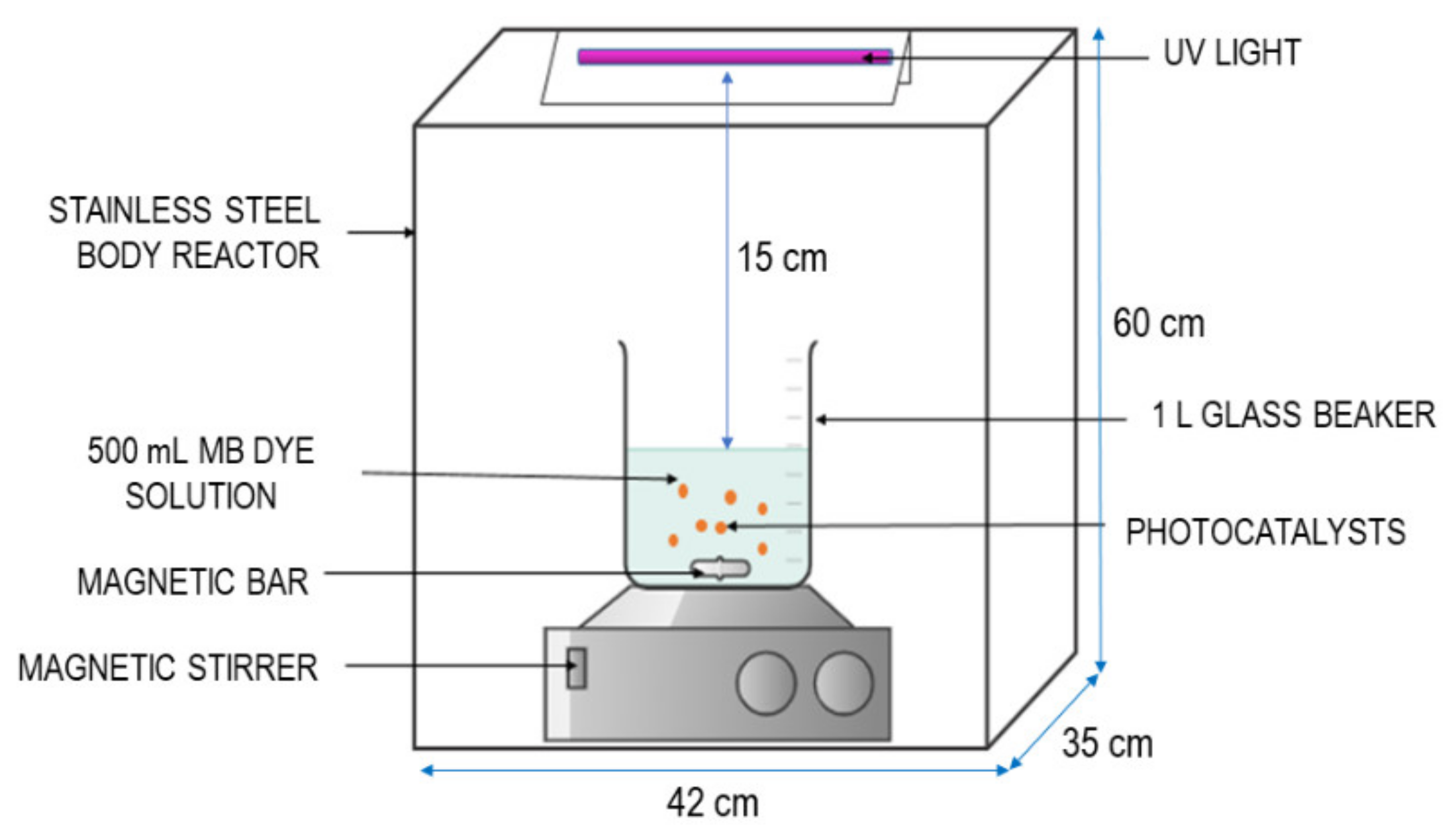
Figure 1. Schematic illustration of photocatalytic reactor.
Membranes 11 00581 g001
Figure 2. FESEM image of nanofibers and average diameter distribution (figure inset). (a) Electrospun PAN nanofibers; (b) TPNF nanofibers.
Membranes 11 00581 g002
Figure 3. FTIR spectra of (a) Electrospun PAN nanofibers; and (b) TPNF nanofibers.
Membranes 11 00581 g003
Figure 4. (a) Layered EDX mapping of TPNF; (b) EDX spectra of TPNF; (c) elemental mapping including (i)—Ti, (ii)—O, and (iii)—C.
Membranes 11 00581 g004
Figure 5. TGA curve of TPNF nanofiber decomposition.
Membranes 11 00581 g005
Figure 6. FESEM morphologies of THNF calcined at different temperatures; (1) 5000 magnification; (2) 10,000 magnification; (3) diameter distribution where (a) THNF400, (b) THNF500, and (c) THNF600.
Membranes 11 00581 g006
Figure 7. XRD patterns. (a) THNF400, (b) THNF500, (c) THNF600.
Membranes 11 00581 g007
Figure 8. (a) UV–Vis diffuse reflectance spectra and (b) Tauc plot for bandgap determination.
Membranes 11 00581 g008
Figure 9. Degradation of MB dye with different catalysts (Catalyst loading = 0.50 g/L, MB dye concentration = 10 ppm, pH of solution = 7).
Membranes 11 00581 g009
Figure 10. Titanium dioxide hollow nanofibers with enhanced photocatalytic properties. (1) The additional surface provided by the inner core and outer shell for molecule adsorption, (2) heterojunction created by mixed-phase photocatalyst, and (3) light scattering effect within the nanofiber interior.
Membranes 11 00581 g010
Figure 11. Effect of photocatalyst dosage on degradation efficiency of MB dye.
Membranes 11 00581 g011
Figure 12. Effect of initial dye concentration on degradation efficiency of MB dye.
Membranes 11 00581 g012
Figure 13. Effect of pH on degradation efficiency of MB dye.
Membranes 11 00581 g013
Figure 14. Effect of hydrogen peroxide concentration on degradation efficiency of MB dye.
Membranes 11 00581 g014
Figure 15. The mechanism for the nucleation and growth of the TiO2 nanoparticles on the surface of PAN nanofibers.
Membranes 11 00581 g015
Table 1. Specific surface area and pore volume of the nanofibers.
SampleSpecific Surface Area (m2/g)Specific Pore Volume (cm3/g)
THNF40013.32160.06354
THNF50043.40850.23490
THNF60081.27760.32716
Publisher’s Note: MDPI stays neutral with regard to jurisdictional claims in published maps and institutional affiliations.