
Innovative Gas-Liquid Membrane Contactor Systems for Carbon Capture and Mineralization in Energy Intensive Industries


Abstract
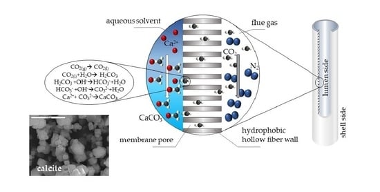
1. Introduction
2. Materials and Methods
2.1. Materials
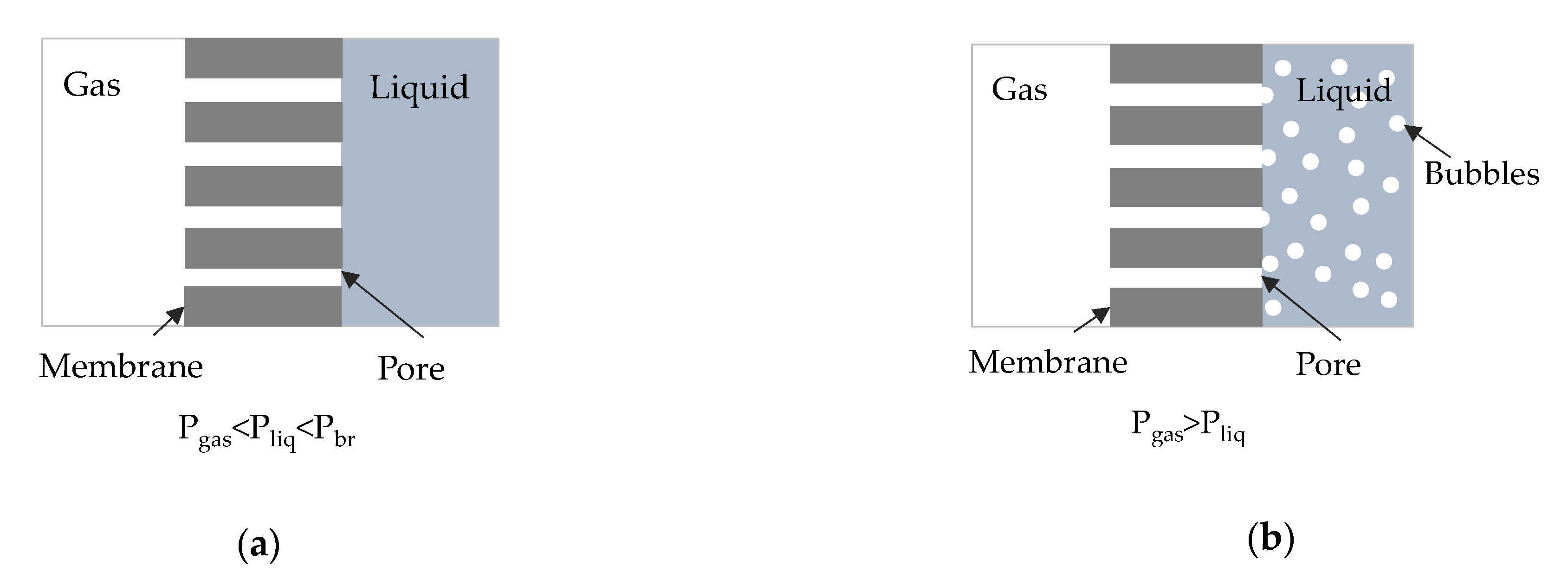
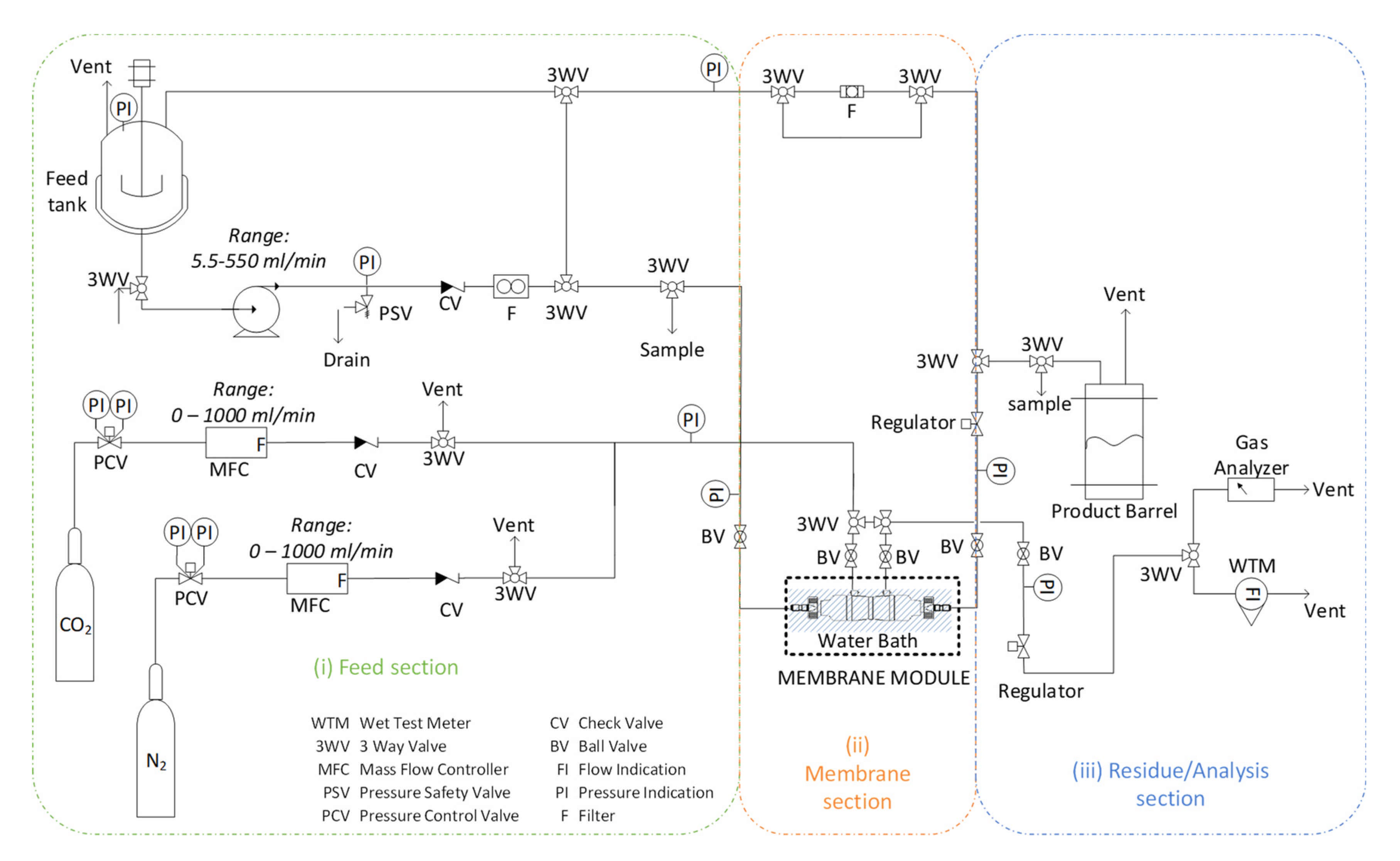
2.2. Experimental Setup and Procedure
2.3. Characterization Methods
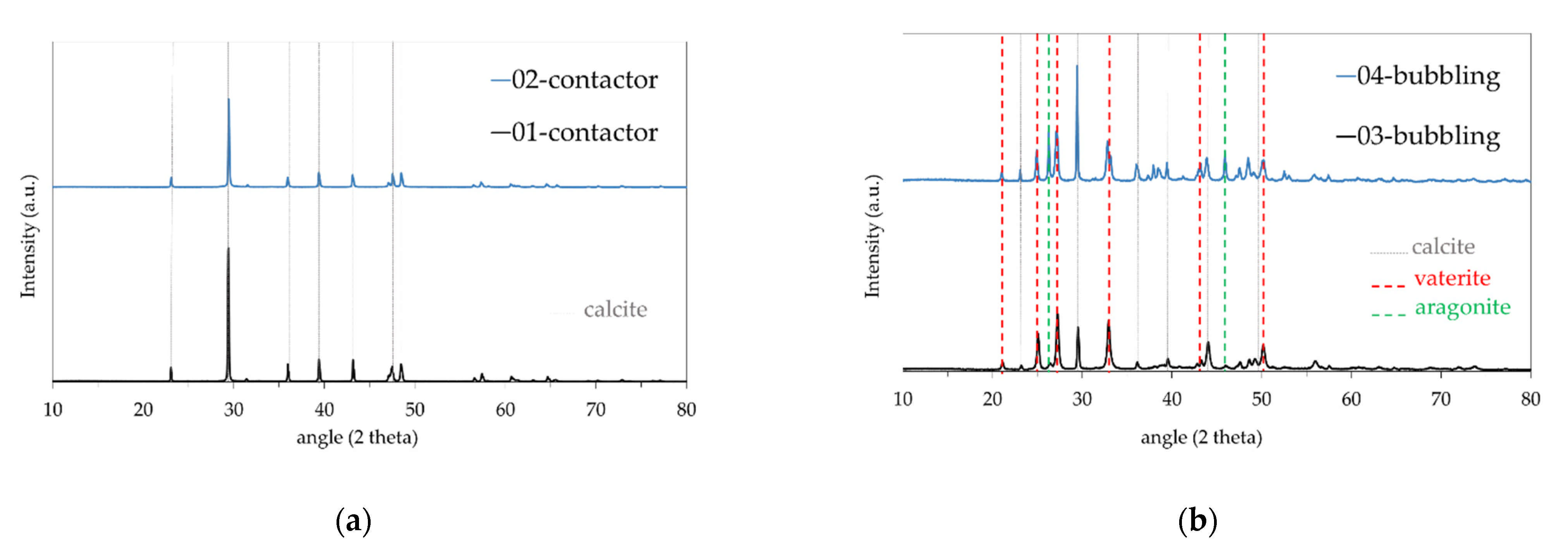
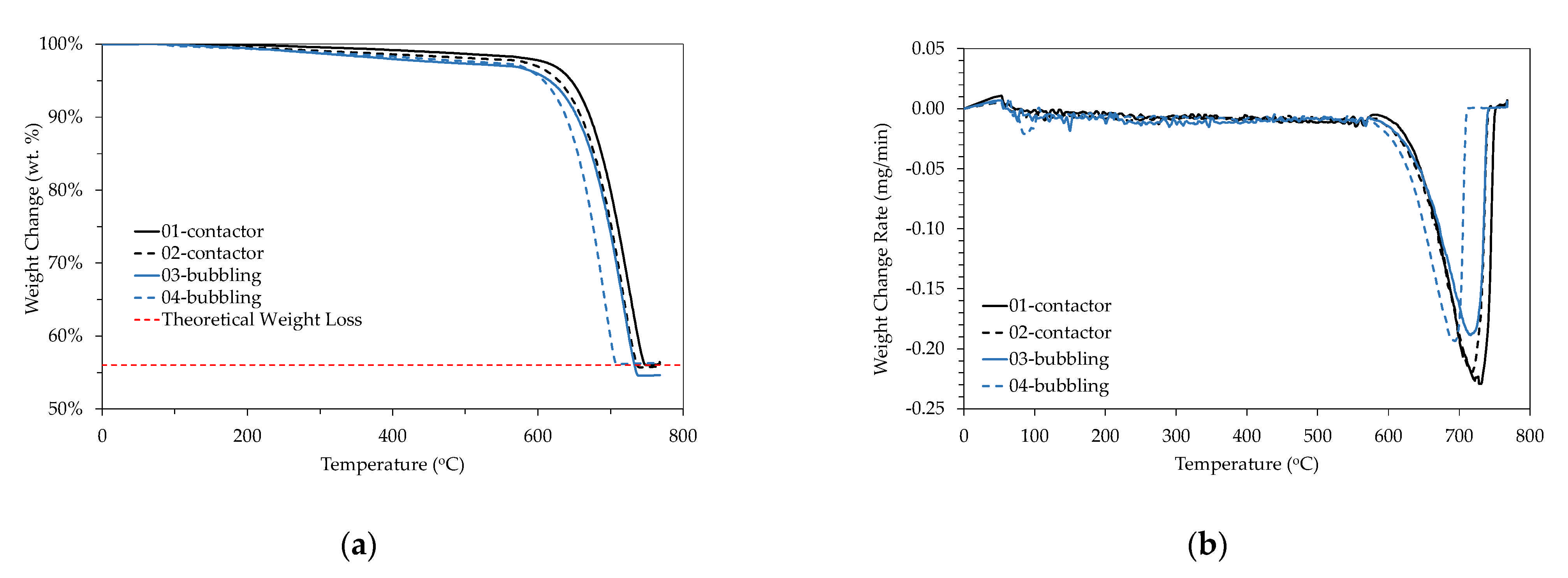
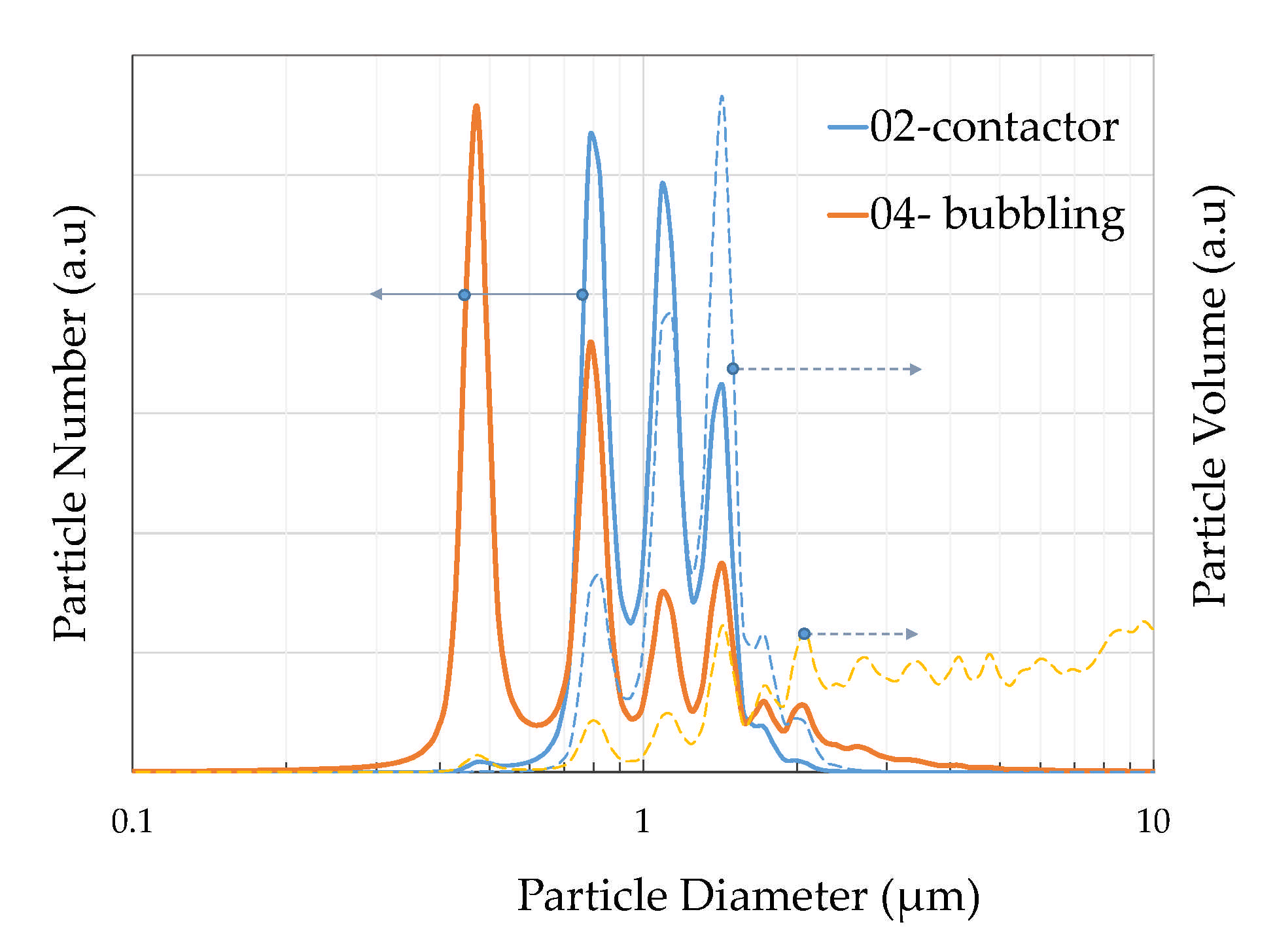
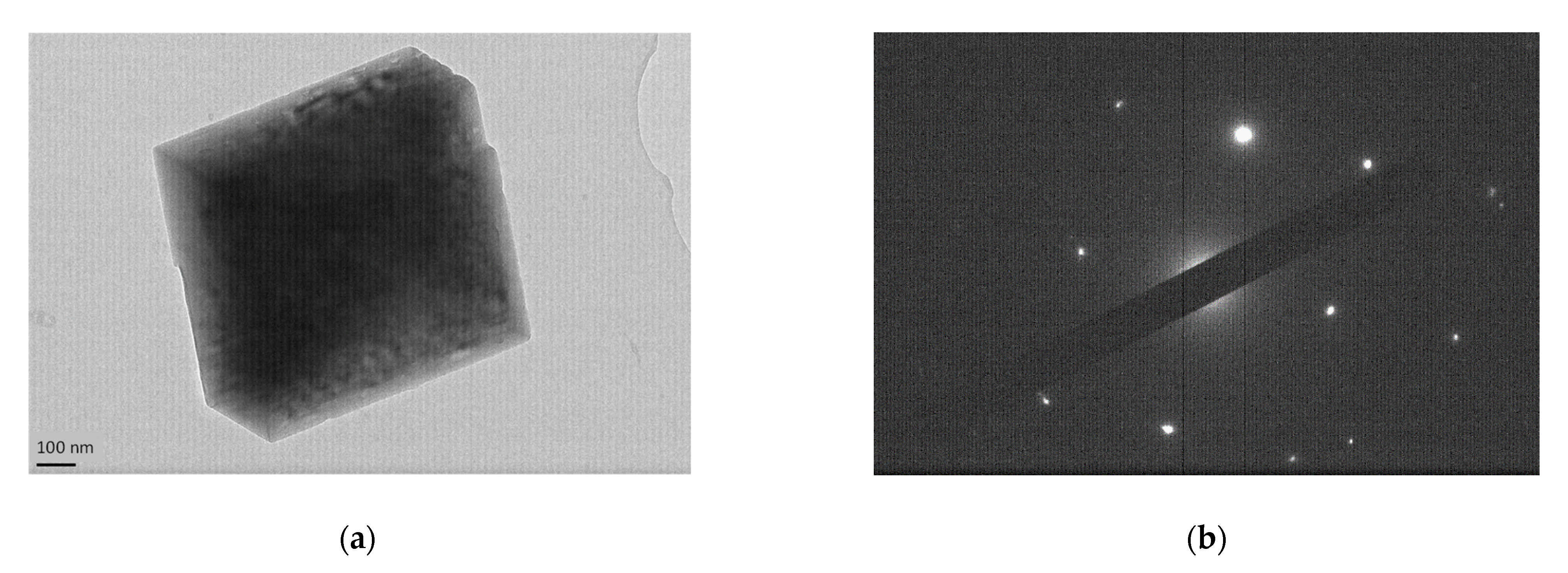
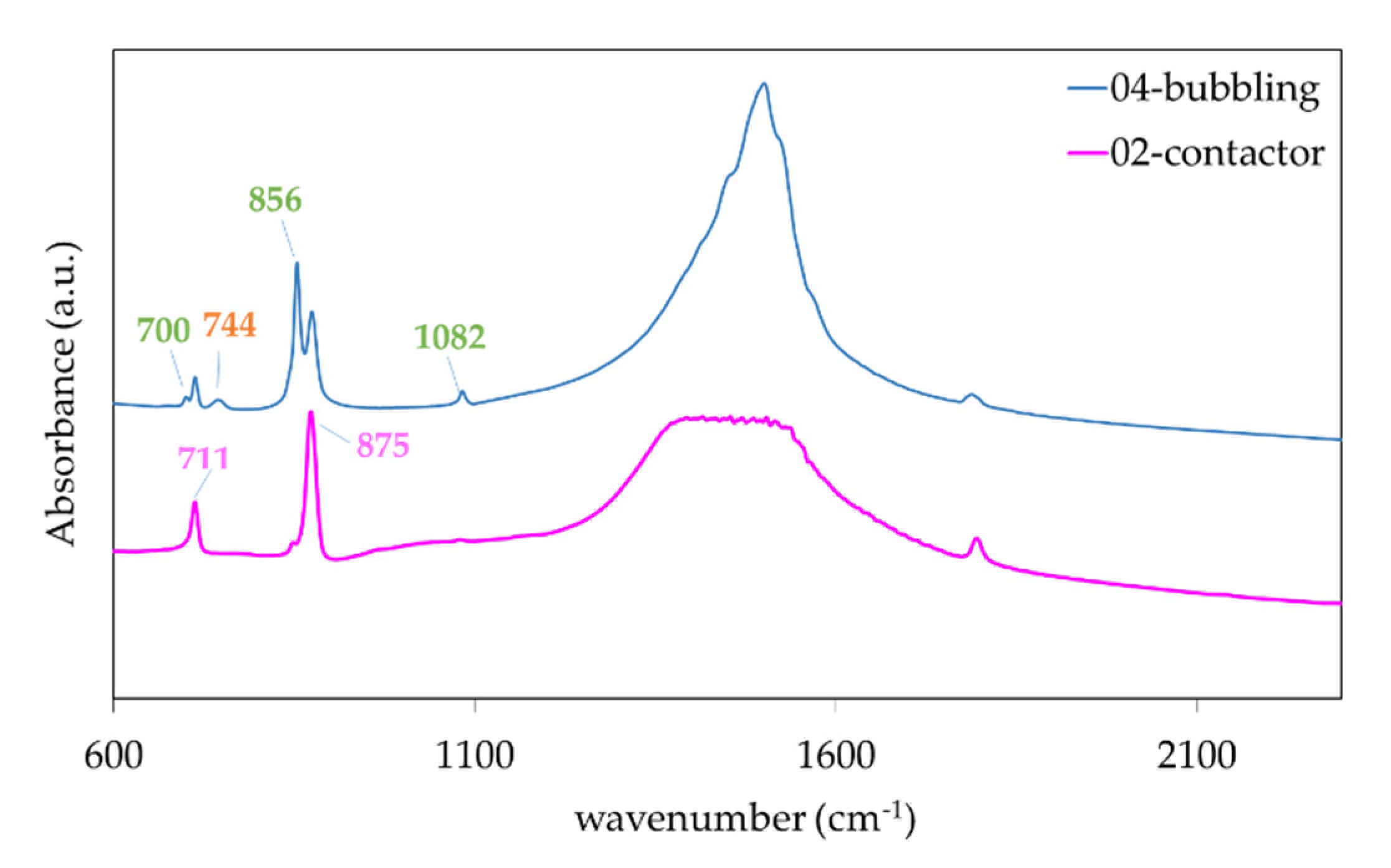
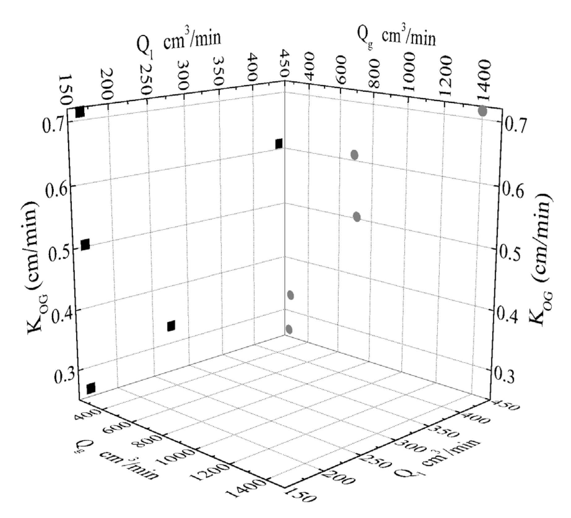
3. Results
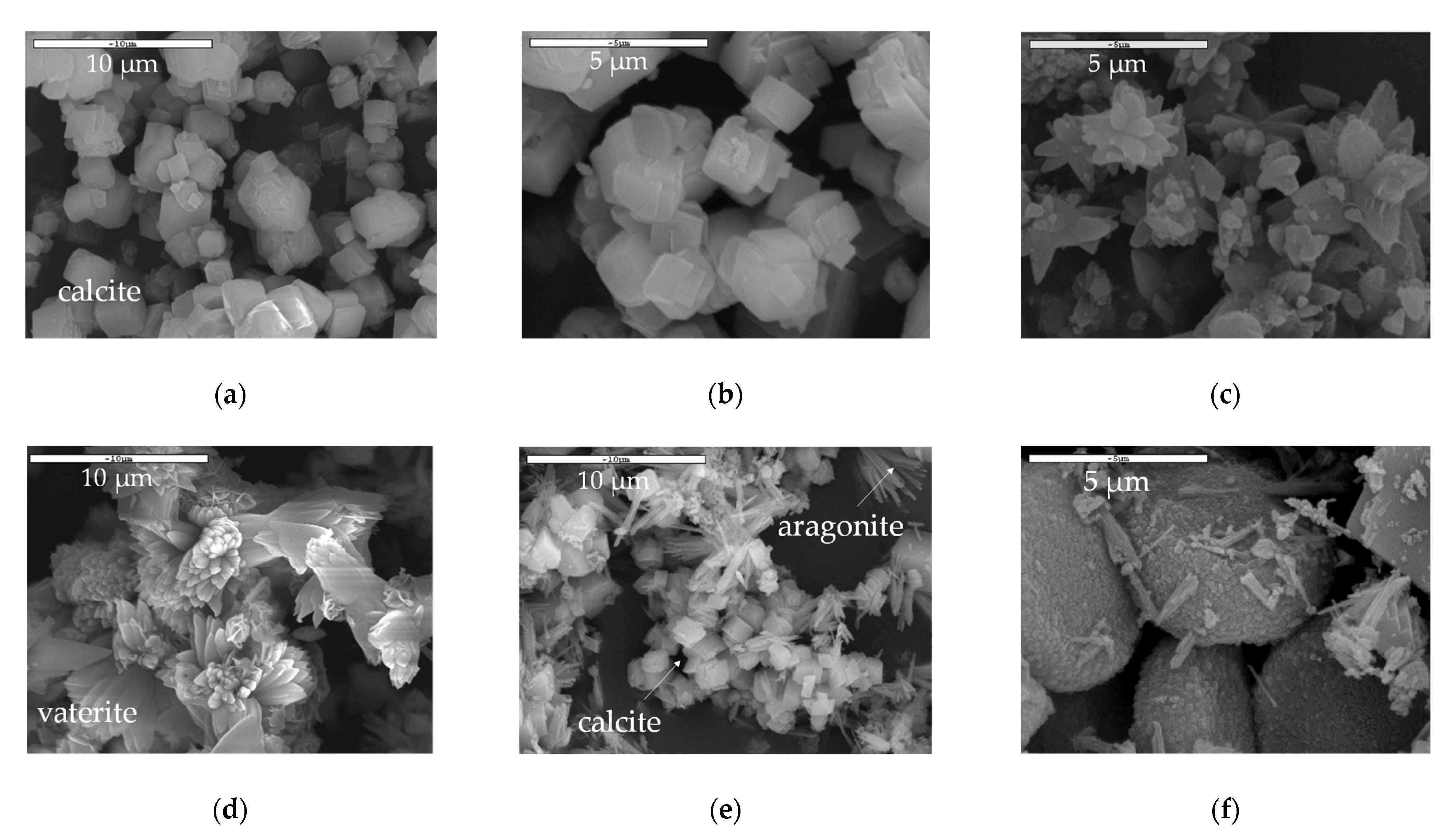
CaCO3 Particles Characterization
4. Discussion
5. Conclusions
Author Contributions
Funding
Institutional Review Board Statement
Informed Consent Statement
Data Availability Statement
Acknowledgments
Conflicts of Interest
References
- Galina, N.R.; Arce, G.L.A.F.; Ávila, I. Evolution of Carbon Capture and Storage by Mineral Carbonation: Data Analysis and Relevance of the Theme. Miner. Eng. 2019, 142, 105879. [Google Scholar] [CrossRef]
- Chen, Z.; Shen, Q.; Gong, H.; Du, M. Preparation of a Novel Dual-Layer Polyvinylidene Fluoride Hollow Fiber Composite Membrane with Hydrophobic Inner Layer for Carbon Dioxide Absorption in a Membrane Contactor. Sep. Purif. Technol. 2020, 248, 117045. [Google Scholar] [CrossRef]
- Geerlings, H.; Zevenhoven, R. CO2 Mineralization—Bridge Between Storage and Utilization of CO2. Annu. Rev. Chem. Biomol. Eng. 2013, 4, 103–117. [Google Scholar] [CrossRef] [PubMed]
- Kim, I.; Yoo, Y.; Son, J.; Park, J.; Huh, I.-S.; Kang, D. Two-Step Mineral Carbonation Using Seawater-Based Industrial Wastewater: An Eco-Friendly Carbon Capture, Utilization, and Storage Process. J. Mater. Cycles Waste Manag. 2020, 22, 333–347. [Google Scholar] [CrossRef]
- Liu, M.; Gadikota, G. Integrated CO2 Capture, Conversion, and Storage To Produce Calcium Carbonate Using an Amine Looping Strategy. Energy Fuels 2019, 33, 1722–1733. [Google Scholar] [CrossRef]
- Wang, L.; Zhang, Z.; Zhao, B.; Zhang, H.; Lu, X.; Yang, Q. Effect of Long-Term Operation on the Performance of Polypropylene and Polyvinylidene Fluoride Membrane Contactors for CO2 Absorption. Sep. Purif. Technol. 2013, 116, 300–306. [Google Scholar] [CrossRef]
- Liu, M.; Gadikota, G. Single-Step, Low Temperature and Integrated CO2 Capture and Conversion Using Sodium Glycinate to Produce Calcium Carbonate. Fuel 2020, 275, 117887. [Google Scholar] [CrossRef]
- Skocek, J.; Zajac, M.; Ben Haha, M. Carbon Capture and Utilization by Mineralization of Cement Pastes Derived from Recycled Concrete. Sci. Rep. 2020, 10, 5614. [Google Scholar] [CrossRef]
- Marocco Stuardi, F.; MacPherson, F.; Leclaire, J. Integrated CO2 Capture and Utilization: A Priority Research Direction. Curr. Opin. Green Sustain. Chem. 2019, 16, 71–76. [Google Scholar] [CrossRef]
- Ryu, M.Y.; You, K.S.; Ahn, J.W.; Kim, H. Effect of the pH and Basic Additives on the Precipitation of Calcium Carbonate during Carbonation Reaction. Resour. Process. 2007, 54, 14–18. [Google Scholar] [CrossRef]
- Sun, B.-C.; Wang, X.-M.; Chen, J.-M.; Chu, G.-W.; Chen, J.-F.; Shao, L. Synthesis of Nano-CaCO3 by Simultaneous Absorption of CO2 and NH3 into CaCl2 Solution in a Rotating Packed Bed. Chem. Eng. J. 2011, 168, 731–736. [Google Scholar] [CrossRef]
- Arti, M.; Youn, M.H.; Park, K.T.; Kim, H.J.; Kim, Y.E.; Jeong, S.K. Single Process for CO2 Capture and Mineralization in Various Alkanolamines Using Calcium Chloride. Energy Fuels 2017, 31, 763–769. [Google Scholar] [CrossRef]
- Romanov, V.; Soong, Y.; Carney, C.; Rush, G.E.; Nielsen, B.; O’Connor, W. Mineralization of Carbon Dioxide: A Literature Review. ChemBioEng Rev. 2015, 2, 231–256. [Google Scholar] [CrossRef]
- Cui, Z.; de Montigny, D. Part 7: A Review of CO2 Capture Using Hollow Fiber Membrane Contactors. Carbon Manag. 2013, 4, 69–89. [Google Scholar] [CrossRef]
- Murnandari, A.; Kang, J.; Youn, M.H.; Park, K.T.; Kim, H.J.; Kang, S.-P.; Jeong, S.K. Effect of Process Parameters on the CaCO3 Production in the Single Process for Carbon Capture and Mineralization. Korean J. Chem. Eng. 2017, 34, 935–941. [Google Scholar] [CrossRef]
- Liendo, F.; Arduino, M.; Deorsola, F.A.; Bensaid, S. Optimization of CaCO3 Synthesis through the Carbonation Route in a Packed Bed Reactor. Powder Technol. 2021, 377, 868–881. [Google Scholar] [CrossRef]
- Ulkeryildiz, E.; Kilic, S.; Ozdemir, E. Nano-CaCO3 Synthesis by Jet Flow. Colloids Surf. Physicochem. Eng. Asp. 2017, 512, 34–40. [Google Scholar] [CrossRef]
- Cosentino, I.; Restuccia, L.; Ferro, G.A.; Liendo, F.; Deorsola, F.; Bensaid, S. Evaluation of the Mechanical Properties of Cements with Fillers Derived from the CO2 Reduction of Cement Plants. Procedia Struct. Integr. 2019, 18, 472–483. [Google Scholar] [CrossRef]
- Youn, M.H.; Park, K.T.; Lee, Y.H.; Kang, S.-P.; Lee, S.M.; Kim, S.S.; Kim, Y.E.; Ko, Y.N.; Jeong, S.K.; Lee, W. Carbon Dioxide Sequestration Process for the Cement Industry. J. CO2 Util. 2019, 34, 325–334. [Google Scholar] [CrossRef]
- Babou-Kammoe, R.; Hamoudi, S.; Larachi, F.; Belkacemi, K. Synthesis of CaCO3 Nanoparticles by Controlled Precipitation of Saturated Carbonate and Calcium Nitrate Aqueous Solutions. Can. J. Chem. Eng. 2012, 90, 26–33. [Google Scholar] [CrossRef]
- Míguez, J.; Porteiro, J.; Pérez-Orozco, R.; Gómez, M. Technology Evolution in Membrane-Based CCS. Energies 2018, 11, 3153. [Google Scholar] [CrossRef]
- Nogalska, A.; Trojanowska, A.; Garcia-Valls, R. Membrane Contactors for CO2 Capture Processes—Critical Review. Phys. Sci. Rev. 2017, 2, 1–7. [Google Scholar] [CrossRef]
- Ulatowski, K.; Sobieszuk, P.; Mróz, A.; Ciach, T. Stability of Nanobubbles Generated in Water Using Porous Membrane System. Chem. Eng. Process. Process Intensif. 2019, 136, 62–71. [Google Scholar] [CrossRef]
- Pellegrino, J.; Schulte, L.R.; De la Cruz, J.; Stoldt, C. Membrane Processes in Nanoparticle Production. J. Membr. Sci. 2017, 522, 245–256. [Google Scholar] [CrossRef]
- Wang, K.T.; Wang, Y.J.; Chen, G.G.; Luo, G.S.; Wang, J.D. Enhancement of Mixing and Mass Transfer Performance with a Microstructure Minireactor for Controllable Preparation of CaCO3 Nanoparticles. Ind. Eng. Chem. Res. 2007, 46, 6092–6098. [Google Scholar] [CrossRef]
- Jia, Z.; Chang, Q.; Mamat, A. Preparation of Nanoparticles with a Semi-Batch Gas–Liquid Membrane Contactor. Chem. Eng. Process. Process Intensif. 2011, 50, 810–814. [Google Scholar] [CrossRef]
- Jia, Z.; Chang, Q.; Qin, J.; Mamat, A. Preparation of Calcium Carbonate Nanoparticles with a Continuous Gas-Liquid Membrane Contactor: Particles Morphology and Membrane Fouling. Chin. J. Chem. Eng. 2013, 21, 121–126. [Google Scholar] [CrossRef]
- Jia, Z.; Chang, Q.; Qin, J.; Hong, X. Preparation of Nanoparticles with a Gas–Liquid Membrane Contactor. J. Membr. Sci. 2009, 342, 1–5. [Google Scholar] [CrossRef]
- Bazhenov, S.D.; Bildyukevich, A.V.; Volkov, A.V. Gas-Liquid Hollow Fiber Membrane Contactors for Different Applications. Fibers 2018, 6, 76. [Google Scholar] [CrossRef]
- Li, L.; Ma, G.; Pan, Z.; Zhang, N.; Zhang, Z. Research Progress in Gas Separation Using Hollow Fiber Membrane Contactors. Membranes 2020, 10, 380. [Google Scholar] [CrossRef]
- Pantoleontos, G.; Kaldis, S.P.; Koutsonikolas, D.; Grammelis, P.; Sakellaropoulos, G.P. CO2 Absorption in a Mini-module Membrane Contactor. In Global Warming; Dincer, I., Hepbasli, A., Midilli, A., Karakoc, T.H., Eds.; Green Energy and Technology; Springer: Boston, MA, USA, 2010; pp. 307–313. ISBN 978-1-4419-1016-5. [Google Scholar]
- Ropp, R.C. Encyclopedia of the Alkaline Earth Compounds; Elsevier: Amsterdam, The Netherlands, 2013; ISBN 978-0-444-59550-8. [Google Scholar]
- Karoor, S. Gas Separation Using Microporous Hollow Fiber Membranes. Ph.D. Thesis, Stevens Institute of Technology, Hoboken, NJ, USA, 1992. [Google Scholar]
- Chen, P.C.; Tai, C.Y.; Lee, K.C. Morphology and Growth Rate of Calcium Carbonate Crystals in a Gas-Liquid-Solid Reactive Crystallizer. Chem. Eng. Sci. 1997, 52, 4171–4177. [Google Scholar] [CrossRef]
- Declet, A.; Reyes, E.; Suarez, O.M. Calcium Carbonate Precipitation: A Review of the Carbonate Crystallization Process and Applications in Bioinspired Composites. Rev. Adv. Mater. Sci. 2016, 44, 87–107. [Google Scholar]
- Al Omari, M.M.H.; Rashid, I.S.; Qinna, N.A.; Jaber, A.M.; Badwan, A.A. Calcium Carbonate. In Profiles of Drug Substances, Excipients and Related Methodology; Elsevier: Amsterdam, The Netherlands, 2016; Volume 41, pp. 31–132. ISBN 978-0-12-804784-2. [Google Scholar]
- Rangwala, H.A. Absorption of Carbon Dioxide into Aqueous Solutions Using Hollow Fiber Membrane Contactors. J. Membr. Sci. 1996, 112, 229–240. [Google Scholar] [CrossRef]
- Mavroudi, M.; Kaldis, S.P.; Sakellaropoulos, G.P. Reduction of CO2 Emissions by a Membrane Contacting Process☆. Fuel 2003, 82, 2153–2159. [Google Scholar] [CrossRef]
- Hosseini, E.; Soroodan Miandoab, E.; Stevens, G.W.; Scholes, C.A. Absorption of CO2 from Flue Gas under Oscillating Gas Flow Conditions in Gas-Solvent Hollow Fibre Membrane Contactors. Sep. Purif. Technol. 2020, 249, 117151. [Google Scholar] [CrossRef]
- Jia, Z.; Chang, Q.; Qin, J.; Sun, H. Preparation of Nanoparticles with a Continuous Gas–Liquid Membrane Contactor: Absorption Process. J. Membr. Sci. 2010, 352, 50–54. [Google Scholar] [CrossRef]
- Mavroudi, M.; Kaldis, S.P.; Sakellaropoulos, G.P. A Study of Mass Transfer Resistance in Membrane Gas–Liquid Contacting Processes. J. Membr. Sci. 2006, 272, 103–115. [Google Scholar] [CrossRef]


| 3M™ Liqui-Cel™ MM-1 × 5.5 Series Membrane Module | Property/Value |
|---|---|
| Cartridge configuration | Parallel flow |
| Effective length | 10 cm |
| Membrane material | Polypropylene |
| Membrane porosity | 40% |
| Outer Diameter/Inner Diameter (OD/ID) | 300 μm OD/220 μm ID |
| Number of fibers | 2300 |
| Module diameter | 2.54 cm |
| Test No | Mode of Operation | pH Value (t = 0) | Membrane |
|---|---|---|---|
| 01-contactor | Contactor | 10.40 | polymeric/PP a |
| 02-contactor | Contactor | 10.40 | polymeric/PP |
| 03-bubbling | Bubbling | 11.00 | polymeric/PP |
| 04-bubbling | Bubbling | 10.60 | polymeric/PP |
| Test No | Crystallite Size (nm) |
|---|---|
| 01-contactor | 47.78 |
| 02-contactor | 54.15 |
| 03-bubbling | 30.09 |
| 04-bubbling | 54.15 |
| Distribution Analysis | Contactor Mode (nm) | Bubbling Mode (nm) |
|---|---|---|
| Dn 10% | 786.29 | 451.46 |
| Dn 50% | 1037.68 | 786.29 |
| Dn 90% | 1434.26 | 1647.66 |
| Dv 10% | 862.47 | 1307.57 |
| Dv 50% | 1307.57 | 3616.04 |
| Dv 90% | 1647.66 | 8704.8 |
| No | T (°C) | Pg (bar) | Qg,in (cm3/min) | Qg,out (cm3/min) | Ql (cm3/min) | CO2 Removal | yCO2,in (%) | yCO2,out (%) | KOG (cm/min) |
|---|---|---|---|---|---|---|---|---|---|
| 1 | 25.8 | 1.1 | 690 | 590 | 440.48 | 0.7186 | 19.08 | 6.28 | 0.610 |
| 2 | 25 | 1.1 | 280 | 220 | 275.30 | 0.8326 | 18.78 | 4.00 | 0.330 |
| 3 | 25.8 | 1.1 | 270 | 230 | 165.18 | 0.7558 | 18.80 | 5.39 | 0.264 |
| 4 | 25 | 1.1 | 710 | 610 | 165.18 | 0.6400 | 18.95 | 7.94 | 0.503 |
| 5 | 25 | 1.1 | 1400 | 1270 | 165.18 | 0.5018 | 19.32 | 10.61 | 0.713 |
Publisher’s Note: MDPI stays neutral with regard to jurisdictional claims in published maps and institutional affiliations. |
© 2021 by the authors. Licensee MDPI, Basel, Switzerland. This article is an open access article distributed under the terms and conditions of the Creative Commons Attribution (CC BY) license (https://creativecommons.org/licenses/by/4.0/).
Share and Cite
Asimakopoulou, A.; Koutsonikolas, D.; Kastrinaki, G.; Skevis, G. Innovative Gas-Liquid Membrane Contactor Systems for Carbon Capture and Mineralization in Energy Intensive Industries. Membranes 2021, 11, 271. https://doi.org/10.3390/membranes11040271
Asimakopoulou A, Koutsonikolas D, Kastrinaki G, Skevis G. Innovative Gas-Liquid Membrane Contactor Systems for Carbon Capture and Mineralization in Energy Intensive Industries. Membranes. 2021; 11(4):271. https://doi.org/10.3390/membranes11040271
Chicago/Turabian StyleAsimakopoulou, Akrivi, Dimitrios Koutsonikolas, Georgia Kastrinaki, and George Skevis. 2021. "Innovative Gas-Liquid Membrane Contactor Systems for Carbon Capture and Mineralization in Energy Intensive Industries" Membranes 11, no. 4: 271. https://doi.org/10.3390/membranes11040271
APA StyleAsimakopoulou, A., Koutsonikolas, D., Kastrinaki, G., & Skevis, G. (2021). Innovative Gas-Liquid Membrane Contactor Systems for Carbon Capture and Mineralization in Energy Intensive Industries. Membranes, 11(4), 271. https://doi.org/10.3390/membranes11040271