1. Introduction
Humanity is facing the challenge of clean water resource depletion as predictions show that half of humanity may live in regions with water stress problem by 2030 [
1]. This situation appears worse if other factors are included such as population growth, the evolving economy, water resource pollution and climate change. Consequently, it is critical to find solutions to increase fresh water production and to provide safe drinking water for the world’s growing population while limiting energy requirements.
Seawater desalination has attracted growing attention in the last few decades as an alternative technology for fresh water augmentation. However, seawater desalination inevitably costs significantly more than treatment of any other surface water resource. Indeed, with consideration of the difference in salinity between raw water (seawater) and fresh water (under World Health Organization tap water regulations), desalination induces such a great difference in chemical potential that it inevitably consumes, from a thermodynamics point of view, a high amount of energy to remove dissolved salt.
Nowadays, the most energy-efficient seawater desalination technology is reverse osmosis (RO). This technology has improved considerably in the last five decades and is at present the most developed seawater desalination technology at industrial scale [
2]. These improvements are mainly due to the enhancement of membrane performance (with a quite good compromise between permeability and selectivity), pump efficiency and the implementation of energy recovery devices (ERDs), which result in considerable decreases in energy consumption (from approximatively 15 kWh/m
3 in the early 1970s to less than 2 kWh/m
3 today). Nevertheless, this consumption can be further reduced by optimizing the pilot design and its associated operating mode. A new trend is to work with the batch system where the recirculation of the rejected brine goes back into the feed tank. This process is named batch and semi-batch RO configurations. Additionally, there is room for improvement from an energetic standpoint considering the size of the feed tank, the profile pressure applied to the ERD and pump efficiencies.
In continuous mode, the feed pressure depends on (1) the desired conversion yield and (2) the salt concentration to guarantee a minimum permeate flow at the end of the spiral wound. Whereas batch RO is, in theory, the only configuration where the required minimum energy is equal to the thermodynamic theoretical minimal specific energy consumption (SEC), by matching/adapting the applied pressure to the increasing osmotic pressure [
3]. Thus, by having the possibility to reduce the difference between pump pressure and osmotic pressure, batch RO makes it possible to control and minimize the polarization layer. It has to be noted that, in reality, it is impossible to reach such a limit due to many potential energy losses such as electrical energy conversion into mechanical energy efficiency (pump efficiency) as well as the concentration of polarization (selective mass transfer), pressure loss (friction) and ERD energy loss. However, the minimum practical energy consumption is reduced by nearly 30% when one passes from a continuous RO configuration to a batch configuration (from 1.54 kWh/m
3 to 1.1 kWh/m
3) [
3].
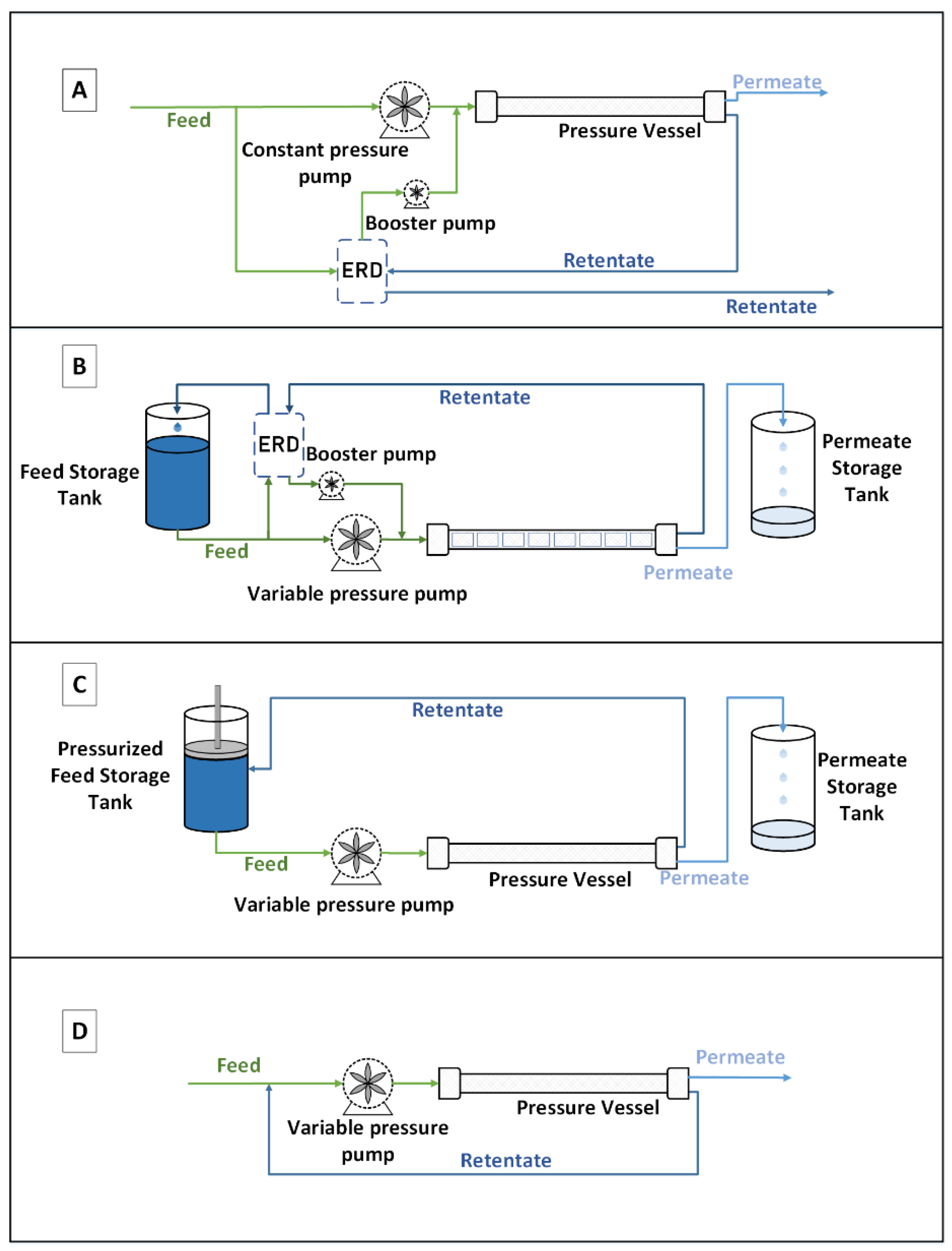
Indeed, in a conventional continuous configuration (
Figure 1, Type A), the pressure is fixed according to the osmotic pressure of the outlet of the last pressure vessel module; this is to satisfy the objective of treatment in terms of water recovery. In the batch configuration, feed water is pumped and contained in a feed tank, which can be pressurized or not depending on the configuration. The feed is, then pumped through a pressurized membrane vessel where the RO filtration occurs. The permeate is recovered, while the retentate is recirculated to the feed tank resulting in an increase of its concentration. This operation, named a pass, is reconducted several times until reaching the desired water recovery. Then the feed tank is emptied (corresponding to the final concentrate) and refilled to start a new cycle. Two configurations can be adapted in batch mode. The first one requires an ERD to recover the pressure and transfer it to the feed stream (
Figure 1, Type B), and the second one requires a pressurized feed tank (
Figure 1, Type C). This last configuration, with the pressurized tank, seems, at first sight, easier, but it might be very constraining and difficult to set up at a larger scale. The feed pump in Type A delivers constant pressure, while it delivers time variable pressure in the rest of the processes, to keep producing permeate flux as feed osmotic pressure increases with time. ERDs are used to recover energy from the brine in processes A and B. The pressurized tank is schemed as a tank with a piston that retains the brine’s energy, acting as an ERD.
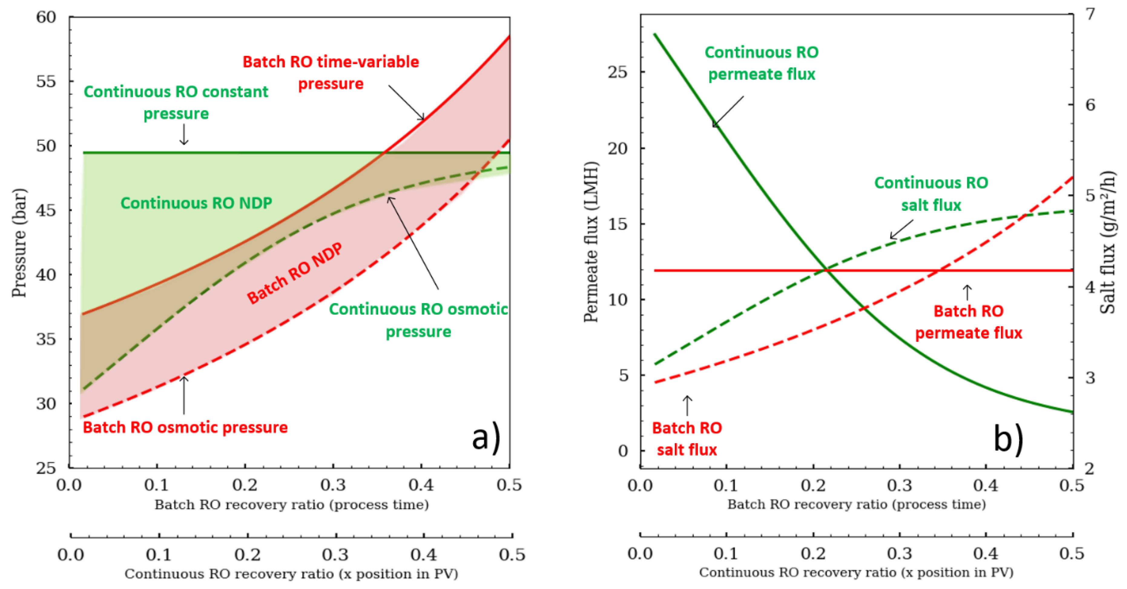
The advantage of working with the batch RO configuration is that the pressure can be modulated and adapted precisely according to the osmotic pressure evolution (
Figure 2). Batch RO can operate similar to an N-stage configuration by increasing pressure like a staircase function to overcome increasing osmotic pressure between stages. An alternative pressure profile is to place an osmotic pressure sensor (conductometer) to apply enough pressure that would keep the net driving pressure (NDP; NPD = ΔP − Δπ) constant to maintain a constant flux. Any random pressure profile that is greater than the osmotic pressure would be suitable for the batch RO.
Figure 2 was drawn to compare the two different operating modes. The mean permeate flux was fixed at 12 L·m
−2·h
−1 for both configurations. The osmotic pressure stays parallel to the pump pressure for batch RO, whereas the osmotic pressure tends to reach the pump pressure for continuous RO. In continuous RO, the permeate flux is also a function of the module position in the pressure vessel (from 26 to 3 LMH), while in continuous RO, it remains constant as the batch RO pressure was set to deliver constant flux. Thus, the recovery ratio depends on the module’s place in the pressure vessel (PV) for continuous configuration, whereas in batch RO it is a function of the process time. What is also important to note is that the salt convective flux (J
S = J
W·C
S) is different, showing that the scaling risk is not the same.
Another alternative to continuous RO desalination is the semi-batch configuration (
Figure 1, Type D). The main difference with the batch process is that the recirculation stream is mixed instantly with the feed stream, instead of being stored in a feed tank. Feed salinity increases with time; thus, the pump pressure also increases to keep a positive permeate flux. While the main focus of our study is the modeling of batch RO desalination, it is worth mentioning that the semi-batch process, also known as closed circuit reverse osmosis (CCRO), is patented and commercialized by Desalitech Company under the name of Reflex CCRO [
4]. The company claims a high recovery ratio of up to 98%, energy savings as well as less fouling and scaling. The main findings regarding the performance of CCRO were published in a series of papers exploring all aspects of this technology [
5,
6,
7]. CCRO is now incorporated in different RO software such as ROSA [
8], LewaPlus [
9] and PROTON [
10].
Research on batch configuration is still limited, and large-scale use remains under investigation. Some patents were introduced by Szucz et al. [
11], Oklejas [
12] and Warsinger et al. [
13]. Warsinger et al. [
14] modeled the batch configuration and semi-batch configurations and found that they can save up to 64% and 37% of energy, respectively, for brackish water at high water recovery. They explained that the batch configuration exhibits higher energy efficiency than CCRO does because of the high entropy generated in CCRO caused by mixing brine with feed water, which is lessened in the batch process where the concentration difference between the brine and the feed is much lower (both stream concentrations increase). Another advantage of the batch mode is the less fouling propensity due to better control of the effective driving force, which allows to control the polarization concentration phenomena and thus reduces fouling. Warsinger et al. [
15] explored the effect of batch configuration on scaling. They concluded that due to the shorter residence time of scalants and the cyclic concentration of the seawater feed, batch RO is more likely to resist inorganic fouling of Gypsum CaSO
4 and could reach high recoveries greater than 75% while continuous RO is limited to 60% in order to avoid scaling under the same conditions.
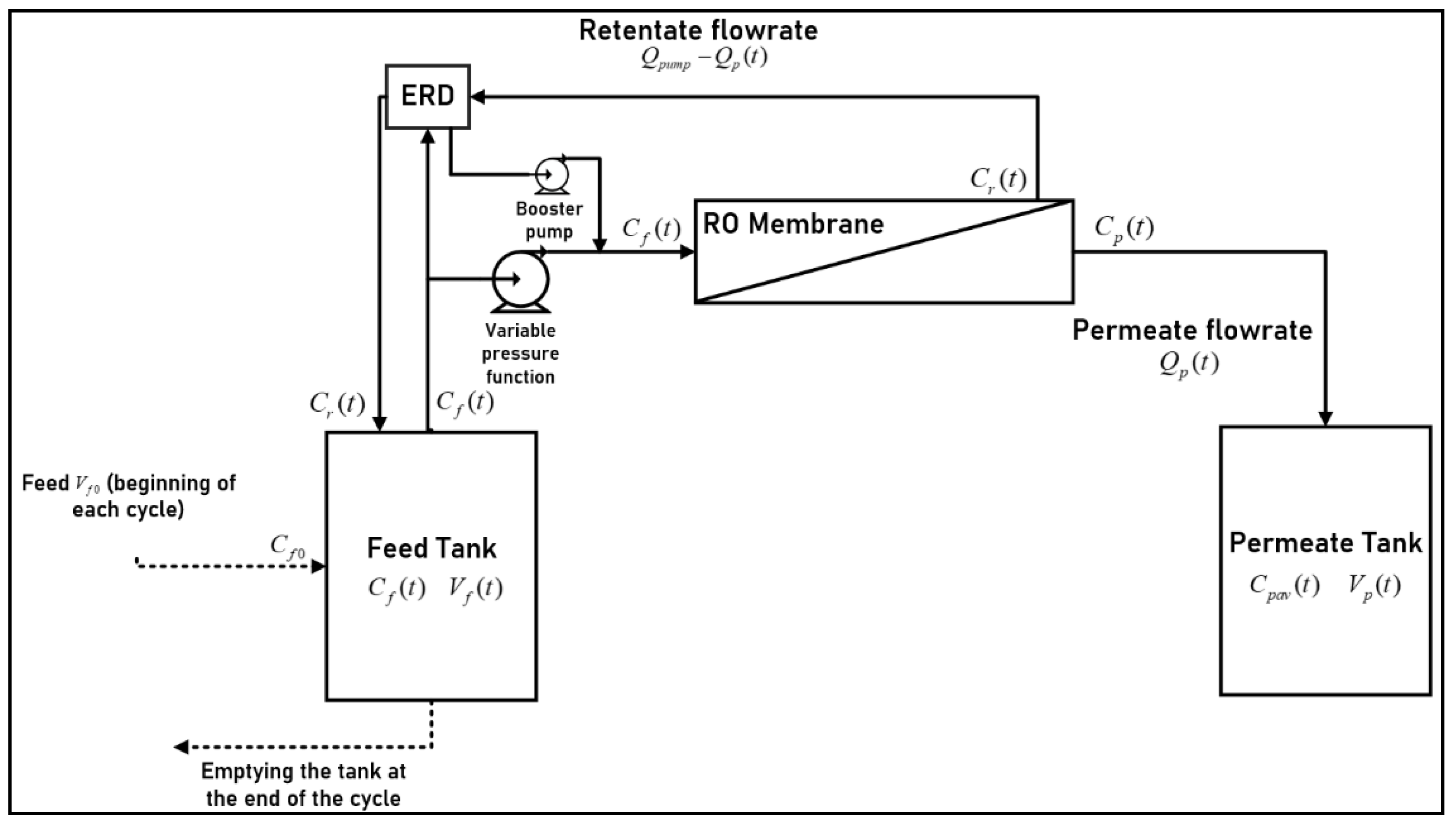
Our paper proposes an approach to modeling the batch RO process that is based on the works of Slater et al. [
16] and is different than recent models. We opted for this model because it allows the use of time-dependent pressure profiles and detailed description of process variable dynamics, using a forward and direct analytical approach delivering differential equation describing the whole batch RO system concentrations. A Python algorithm was developed to that end. Validation is conducted by comparison to existing models and experimental data. An energetic comparison between batch RO and continuous RO configurations is discussed to highlight energetic performances. The batch RO process is also simulated under a wide set of parameter variations and under different pressure profiles to explore its energetic response.
3. Results
3.1. Model Validation: Comparison with Experimental Results
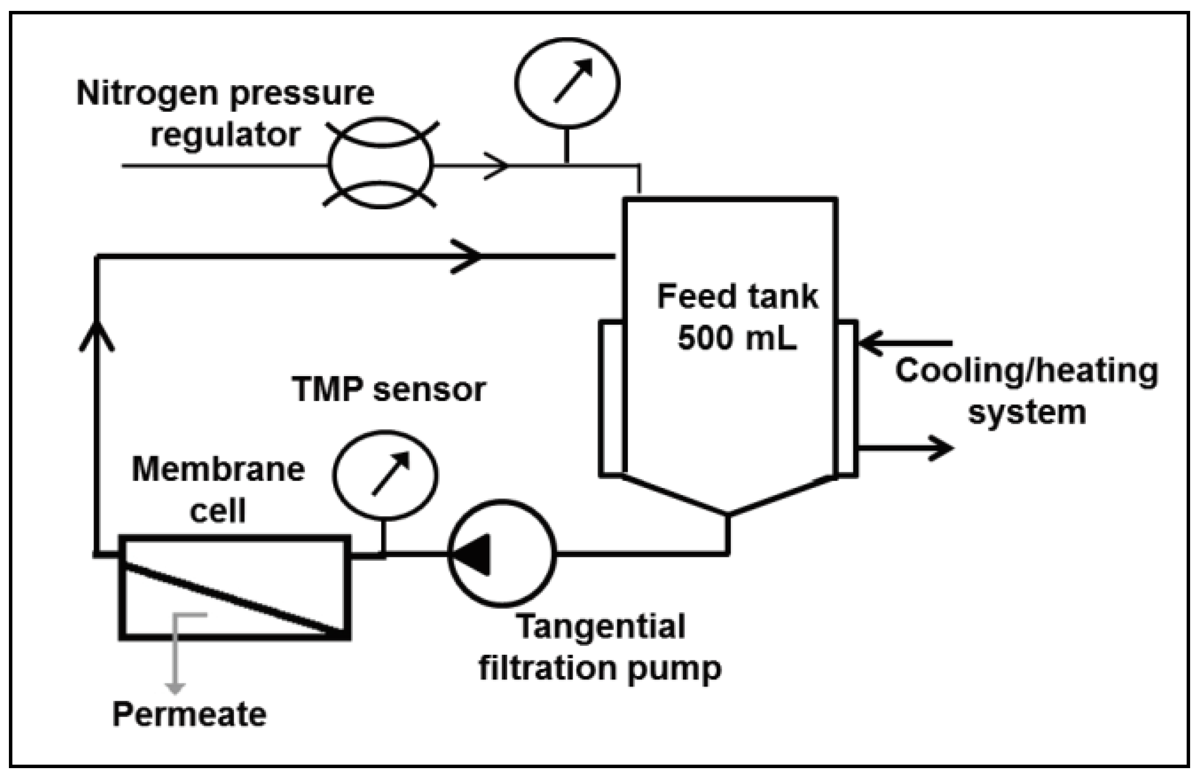
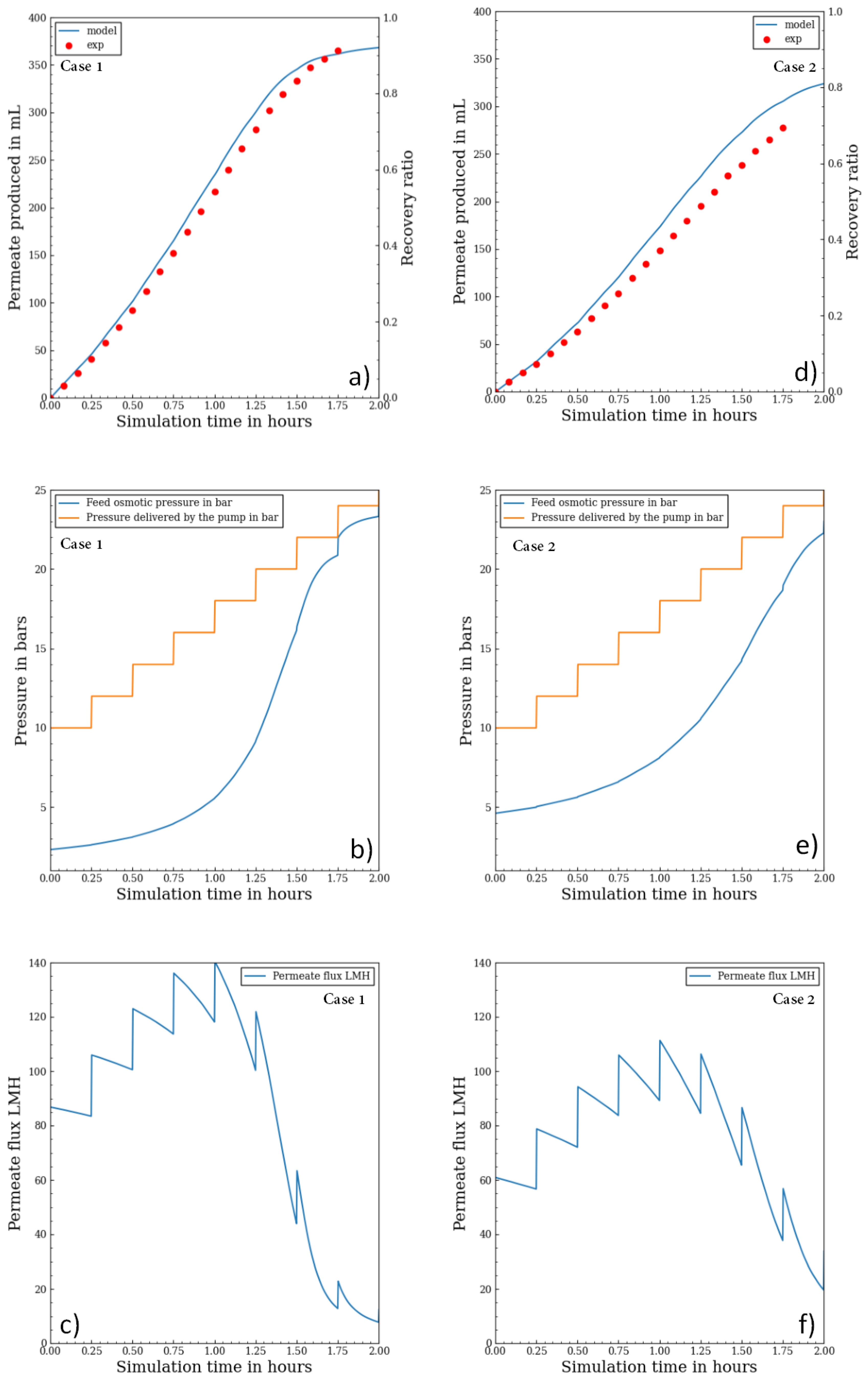
Experimental data from the experimental set-up were used to verify the model. The first case study was done a simple aqueous salt (NaCl) solution of 3 g/L whereas the second case was performed with 6 g/L. The initial feed tank was set at 0.4 L, and a staircase pressure function of 10 bar + 2 bar/15 min was selected.
Figure 6a,d compare cumulative permeate variation results over time between the experiment and model simulation for the first and second case (the different initial feed concentrations are, respectively, 3 g/L and 6 g/L). The results allowed the determination of the mass transfer coefficient (
k). A similar evolution of permeate production at the start of the process was observed, and both plots showed a good agreement between the model and experiment.
Figure 6b,c,e and f show for both cases the osmotic pressure modeling as well as the permeate flux over time and the feed pressure. Pressure plots show how the osmotic pressure tends to reach the pump pressure at the end of the experiment where the feed volume is low leading to high concentration variation. The discontinuities of flux are due to the sudden change in pump pressure since it is a staircase function, which causes the NDP to change suddenly as well. The permeate flux calculation confirms that even with a staircase function, the response is not a monotonic function. In fact, the staircase function leads to a wide permeate flux variation: for the case 1, permeate flux starts at 87 LMH, goes up to 140 LMH and decreases to 10 LMH at the end of process. Similarly, for the case 2, it starts at 60 LMH, goes up to 110 LMH and decreases to 20 LMH. Those variations are not in the favor of the membrane lifetime.
The recovery ratio rate over time was not the same for both cases; it was higher for the case with a lower initial feed salinity. This was explained by the salinity increase rate in the feed tank. If the initial salinity is higher, then osmotic pressure would increase rapidly, and under the same pressure profile and feed tank volume, the production is lower as the NDP is lower.
3.2. Validation by Comparison with Wei et al.
The model developed in the present study was compared to the results of a previous model [
14,
18], validated by the experimental batch RO set-up with a pressurized feed tank. The same conditions displayed in
Table 1 were considered except for a slight difference in the CPF, which was hard to adjust as the
k value was not given.
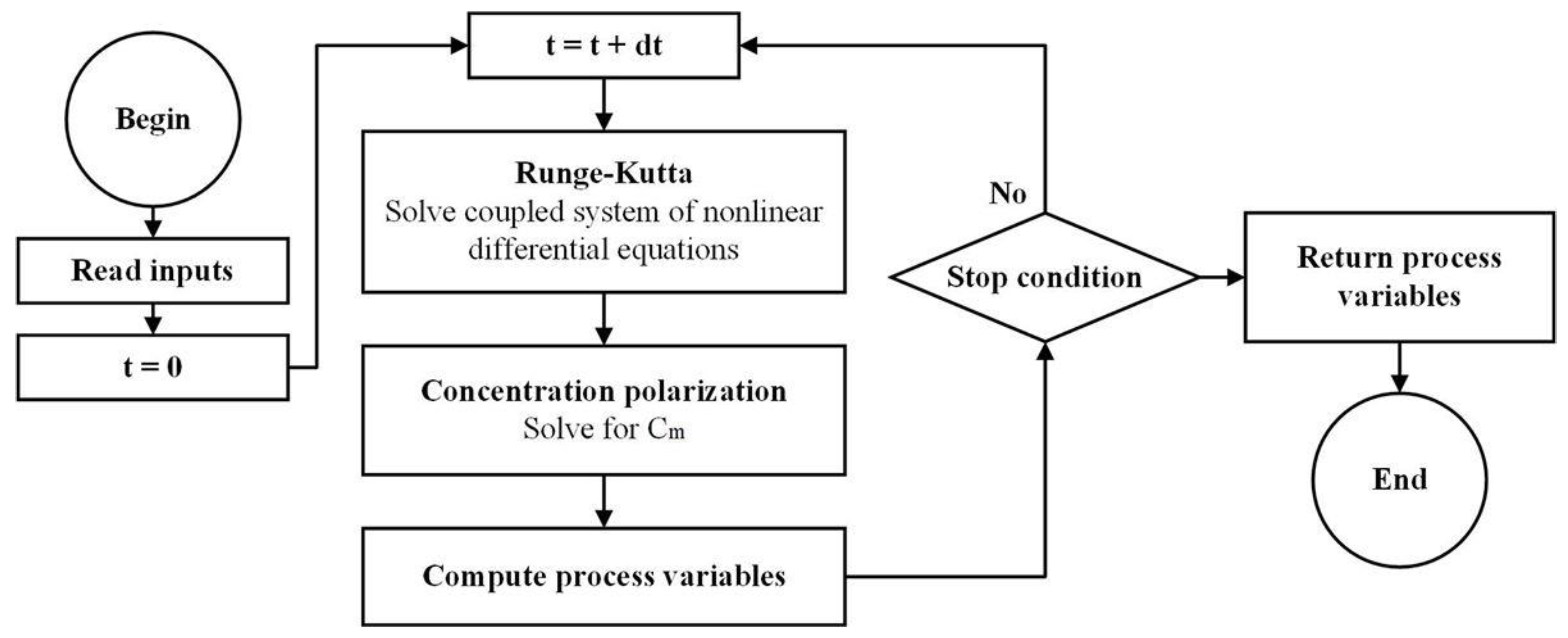
The energetic performances of both models were compared for fifteen cases, each with different permeate fluxes, initial feed concentrations and recovery ratios. SEC was computed according to Equation (19). The results are depicted in
Table 2. The model comparison showed that the SEC estimations are in line with the reference model estimation [
14,
18] with a maximum error of 3.2% (Equation (21)):
The present model indeed tended to slightly overestimate SEC in most cases compared to the reference model. For lower recovery ratios, there was less difference, while the error increased slightly when the recovery ratio increased. CPF was time dependent, and its mean value in time over the range of 0% to 60% was calculated. Its impact depended on permeate flux: The higher the permeate flux, the higher the value of CPF was.
This difference in energetic performance is mainly due to the difference in the models’ equations and hypotheses. While the reference model [
14,
18] uses a finite elements method for calculations, we used an analytical approach with coupled differential equations in order to solve the equation step by step. Additionally, this approach considers CPF to be time dependent, and only the mean value is taken into consideration for comparison. Differences in CP values impact the results of the SEC, as Equation (19) uses wall concentration values at each step to compute SEC. Nevertheless, the whole approach tends to deliver energetic performance in good agreement with the reference model.
3.3. Batch RO vs. Continuous RO: Energetic Comparison
In this part, a comparison between batch and continuous configurations from an energetic stand point is explored for seawater and brackish water. The comparison was based on the present validated model for batch RO and on the SEC expression for continuous RO [
22]. The used parameters are depicted in
Table 3. The feed pressure for the batch RO was calculated to work with a constant permeate flux (15 LMH for seawater and 25 LMH for brackish water).
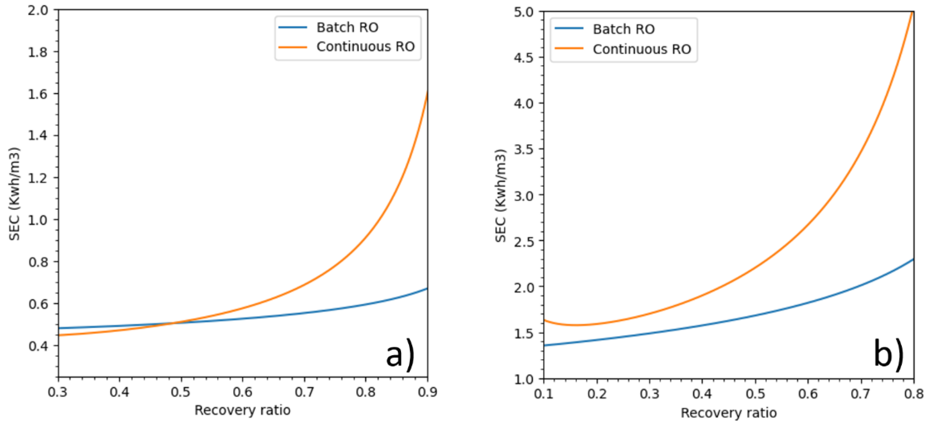
The SEC of batch RO and continuous RO, both using an ERD, over a wide range of recovery ratios are displayed in
Figure 7. If batch RO was more energy efficient than continuous RO was at all recovery ratios for seawater, for brackish water the batch RO was more energy efficient only when the recovery ratios is higher than 50% which is always the case for brackish water. The energetic trends are in accordance with the work of Wei et al. [
18], Werber et al. [
3] and Warsinger et al. [
14]. For seawater, at recovery ratios of 40%, 50% and 60%, batch RO used respectively 17%, 23% and 31% less energy than did continuous RO. For brackish water, at recovery ratios of 60%, 70% and 80%, batch RO used respectively 9%, 19% and 34% less energy than did continuous RO.
3.4. Batch RO and Pressure Profiles for Seawater
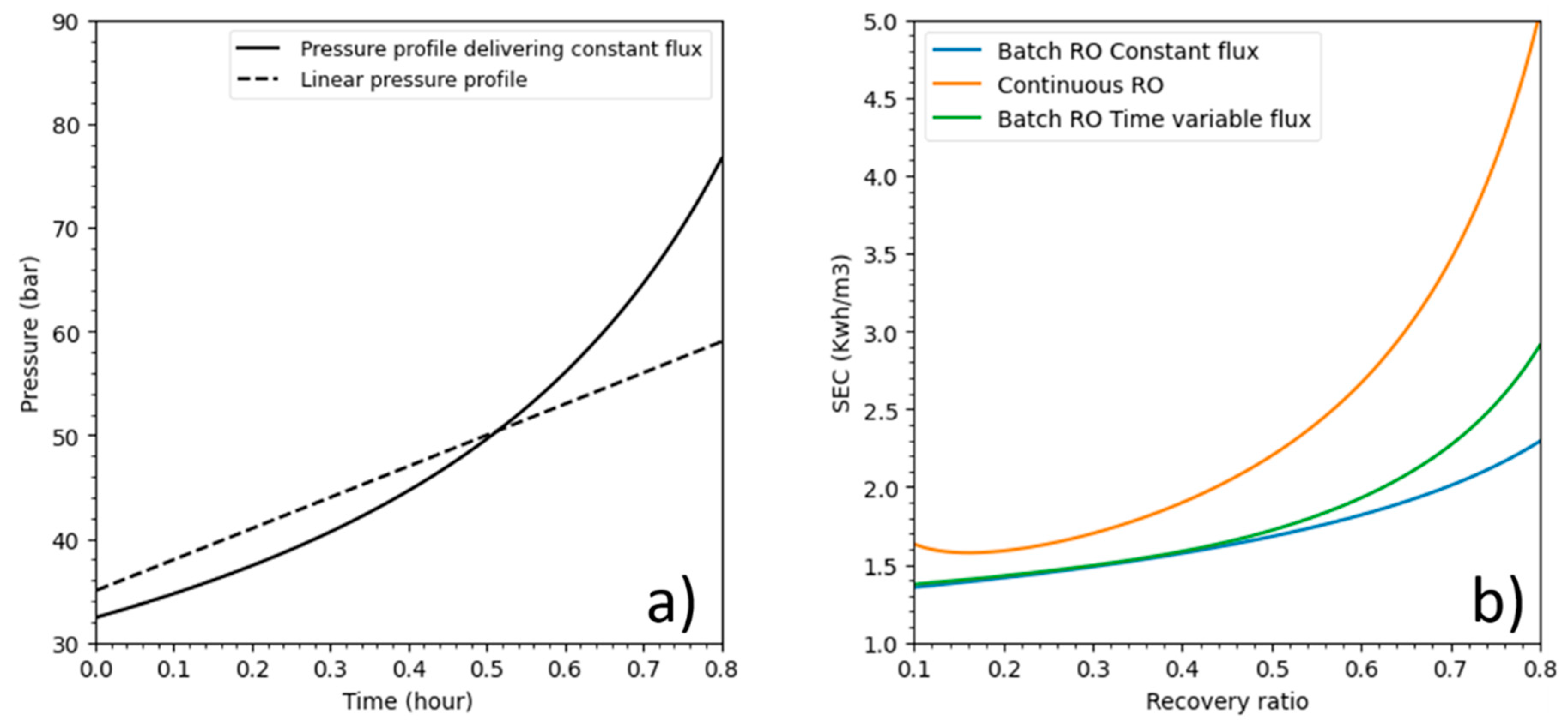
As stated in the introduction, batch RO can operate using any type of pressure profile as long as it remains higher than osmotic pressure during the process. For this part, batch RO pressure profiles were investigated. A linear pressure profile, pressure (
t) = 35 + 30
t (where
t is the operating time in hours), was compared to batch RO under a pressure profile that delivers a constant flux at 15 LMH and a constant pressure for continuous RO. The membrane parameters are the same as in
Table 3.
Figure 8a shows pressure profile plots against time, while
Figure 8b displays energetic responses over recovery ratios.
Both batch RO pressure profiles used considerably less energy than continuous mode at all recoveries especially at high recovery values. Batch RO under the linear pressure profile performed well, especially at recoveries lower than 50% where its SEC was closed to batch RO under a constant flux pressure profile.
As shown in this example, batch RO energy consumption can increase and perhaps would also decrease with a different pressure profile. This proves that the batch RO still needs some improvement to minimize its SEC.
3.5. Impact of Feed Salinity and Feed Volume
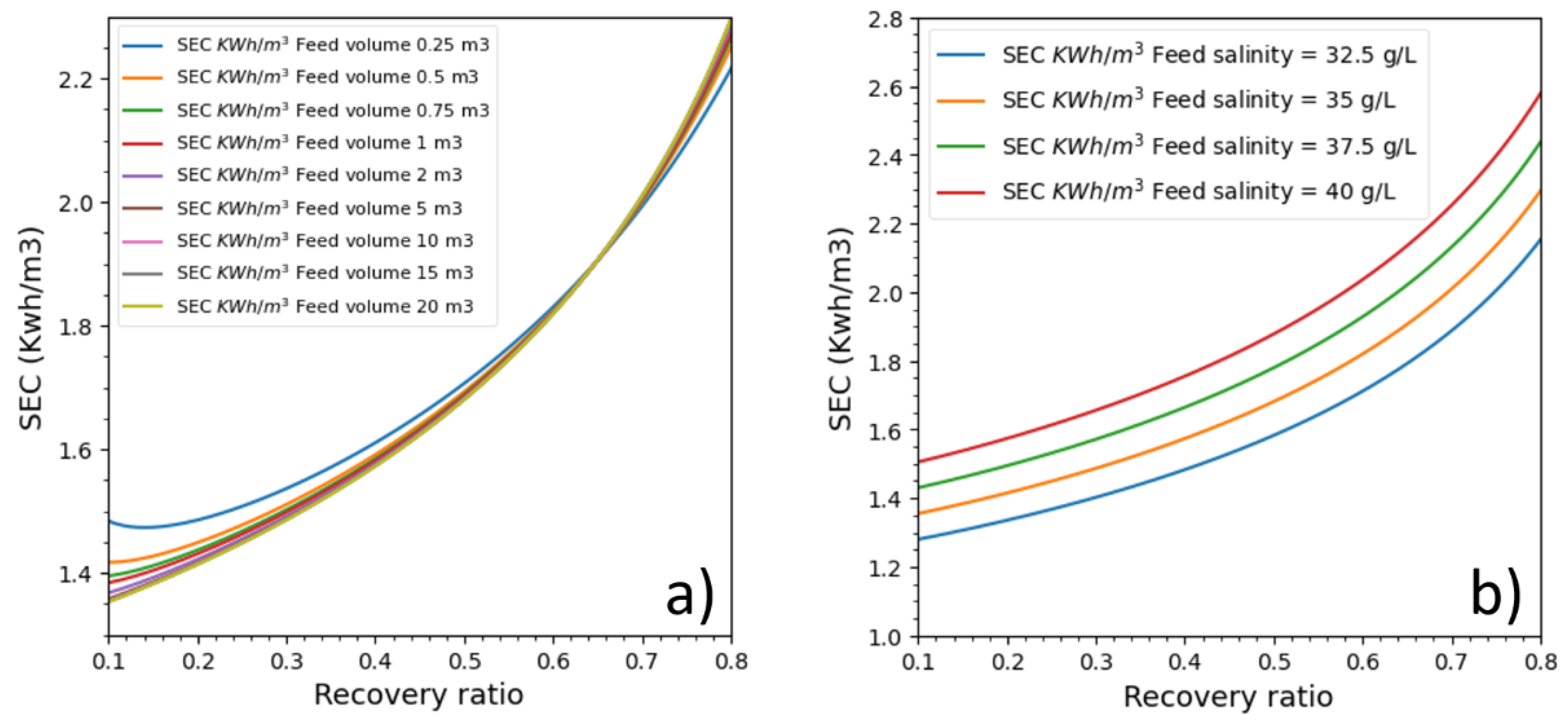
Initial feed salinity and feed volume variations that impact batch RO energetic behavior are analyzed in this part. Nine feed tanks (from 0.25 to 20 m
3: 0.48 L/m
2 of membrane to 38.6 L/m
2) and four cases with different feed salinities (32.5 g/L, 35 g/L, 37.5 g/L and 40 g/L) were studied (see
Figure 9). The membrane permeability was kept to 3 LMH/bar, and the feed pressure was adjusted to deliver a permeate flux of 15 LMH. The ERD efficiency and the pump efficiency were respectively 97% and 85%. The feed tank’s draining and filling were not considered.
The batch RO process was also run under different feed volumes (
Figure 9a). Surprisingly, feed volume seemed to impact batch RO energetics at recovery ratios lower than 50% and higher than 70%, and the feed volume curiously had a zone of zero impact between 55% and 70% recovery ratios. The impact was considerable at recovery ratios below 30% and between feed volumes of 0.25 and 2 m
3. After a recovery ratio of 70%, the order of SEC plots was interestingly inversed.
The energetic response was directly linked to salinity variation. The higher the feed salinity is, the higher the SEC is. Additionally, for all recovery ratios, the difference between SECs was the same for all recovery ratios. It also seems that increasing salinity with a constant of 2.5 g/L causes an SEC increase with an almost constant value 0.15 kWh/m3, which increases with the recovery ratio. This behavior is probably unique to the pressure profile which delivers constant pressure, and it could be that, under a different pressure profile, the variation would have a different energy increase pattern.
Feed volume impact on batch RO is, however, unexpected. While we can explain why lower initial volumes cause SEC to increase (because it causes osmotic pressure to increase quickly while, at higher volumes, dilution slows its increase), it is not clear to us why in a specific interval energetic performance is the same for all volumes and why energy plots are inversed outside this interval.
5. Conclusions
A mathematical model was proposed to simulate the innovative Batch configuration RO. This model has been validated in accordance with experimental data but also with Wei batch model [
18] results. Thus, it made it possible to explore the impact of operating and design parameters. As expected, energetic comparison between batch RO and continuous RO proved that the batch configuration is energy efficient especially at higher conversion rate reducing energy consumption of desalination and thus, its environmental impact and costs.
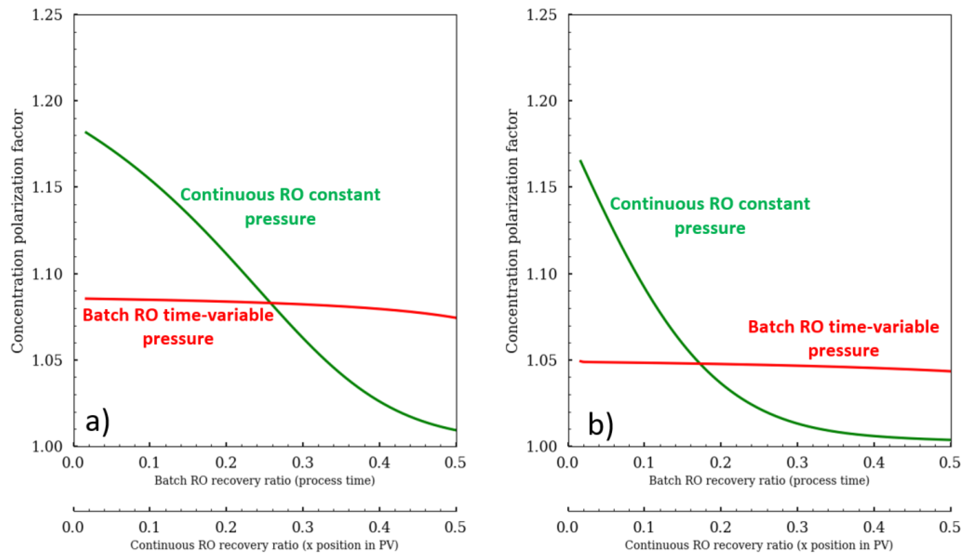
The better energetic gain was due mainly to the variable pressure, which was precisely adjusted to deliver needed energy to produce desired permeate flux and to control the CPF. The control of the CPF value is possible in Batch mode whereas the continuous mode is significantly affected by the CPF on the first pressure vessel modules. Moreover, the control of the CPF value allows the control of the water quality. Then, several parameters impacted batch RO were investigated. Salinity increase caused the SEC to increase in a steady pattern for a rate of 0.15 kwh/m3 for every 2.5 g/L increase. On the other side, the increase of the feed volume has a positive impact but beyond 3.86 L/m2Membrane the energetic gain is negligible. Surprisingly, there was a recovery ratio interval (55–70%) where feed volume didn’t impact SEC at all.
The next decade is likely to witness a rise in the development and investigation of batch processes, thanks to their promising energy efficiency. Further research prospects can include investigation of Batch RO fouling and CP behaviors, impact of stopping time between batch cycles, establishment of detailed cost estimation, and optimization of process variables.
