
Thin Reinforced Ion-Exchange Membranes Containing Fluorine Moiety for All-Vanadium Redox Flow Battery


Abstract
:1. Introduction
2. Materials and Methods
2.1. Materials and Membrane Preparation
2.2. Membrane Characterizations
2.3. VRFB Performance Tests
3. Results and Discussion
4. Conclusions
Author Contributions
Funding
Institutional Review Board Statement
Data Availability Statement
Acknowledgments
Conflicts of Interest
References
- Ulaganathan, M.; Aravindan, V.; Yan, Q.; Madhavi, S.; Skyllas-Kazacos, M.; Lim, T.M. Recent Advancements in All-Vanadium Redox Flow Batteries. Adv. Mater. Interfaces 2016, 3, 1500309. [Google Scholar] [CrossRef]
- Ran, J.; Wu, L.; He, Y.; Yang, Z.; Wang, Y.; Jiang, C.; Ge, L.; Bakangura, E.; Xu, T. Ion exchange membranes: New developments and applications. J. Membr. Sci. 2017, 522, 267–291. [Google Scholar] [CrossRef]
- Parasuraman, A.; Lim, T.M.; Menictas, C.; Skyllas-Kazacos, M. Review of material research and development for vanadium redox flow battery applications. Electrochim. Acta 2013, 101, 27–40. [Google Scholar] [CrossRef]
- Roznyatovskaya, N.; Noack, J.; Mild, H.; Fühl, M.; Fischer, P.; Pinkwart, K.; Tübke, J.; Skyllas-Kazacos, M. Vanadium Electrolyte for All-Vanadium Redox-Flow Batteries: The Effect of the Counter Ion. Batter. 2019, 5, 13. [Google Scholar] [CrossRef] [Green Version]
- Ashurov, K.B.; Abdurakhmanov, B.M.; Iskandarov, S.C.; Turdaliev, T.; Salimboev, A.M.; Adilov, M.M.; Abdusaidov, I.J. Solving the Problem of Energy Storage for Solar Photovoltaic Plants (Review). Appl. Sol. Energy 2019, 55, 119–125. [Google Scholar] [CrossRef]
- Alotto, P.; Guarnieri, M.; Moro, F. Redox flow batteries for the storage of renewable energy: A review. Renew. Sustain. Energy Rev. 2014, 29, 325–335. [Google Scholar] [CrossRef]
- Bae, C.-H.; Roberts, E.; Dryfe, R. Chromium redox couples for application to redox flow batteries. Electrochim. Acta 2002, 48, 279–287. [Google Scholar] [CrossRef]
- Bartolozzi, M. Development of redox flow batteries. A historical bibliography. J. Power Sources 1989, 27, 219–234. [Google Scholar] [CrossRef]
- Prifti, H.; Parasuraman, A.; Winardi, S.; Lim, T.M.; Skyllas-Kazacos, M. Membranes for Redox Flow Battery Applications. Membranes 2012, 2, 275–306. [Google Scholar] [CrossRef] [Green Version]
- Tempelman, C.; Jacobs, J.; Balzer, R.; Degirmenci, V. Membranes for all vanadium redox flow batteries. J. Energy Storage 2020, 32, 101754. [Google Scholar] [CrossRef]
- Hwang, G.-J.; Kim, S.; In, D.-M.; Lee, D.-Y.; Ryu, C.-H. Application of the commercial ion exchange membranes in the all-vanadium redox flow battery. J. Ind. Eng. Chem. 2018, 60, 360–365. [Google Scholar] [CrossRef]
- Charyton, M.; Deboli, F.; Fischer, P.; Henrion, G.; Etienne, M.; Donten, M. Composite Anion Exchange Membranes Fabricated by Coating and UV Crosslinking of Low-Cost Precursors Tested in a Redox Flow Battery. Polymers 2021, 13, 2396. [Google Scholar] [CrossRef] [PubMed]
- Song, H.-B.; Kim, D.-H.; Kang, M.-S. Thin Reinforced Poly(2,6-dimethyl-1,4-phenylene oxide)-based Anion-exchange Membranes with High Mechanical and Chemical Stabilities. Chem. Lett. 2019, 48, 1500–1503. [Google Scholar] [CrossRef]
- Hu, L.; Gao, L.; Di, M.; Jiang, X.; Wu, X.; Yan, X.; Li, X.; He, G. Ion/Molecule-selective transport nanochannels of membranes for redox flow batteries. Energy Storage Mater. 2021, 34, 648–668. [Google Scholar] [CrossRef]
- Crothers, A.R.; Darling, R.M.; Kushner, D.I.; Perry, M.L.; Weber, A.Z. Theory of Multicomponent Phenomena in Cation-Exchange Membranes: Part III. Transport in Vanadium Redox-Flow-Battery Separators. J. Electrochem. Soc. 2020, 167, 013549. [Google Scholar] [CrossRef]
- Song, H.-B.; Park, J.-H.; Park, J.-S.; Kang, M.-S. Pore-Filled Proton-Exchange Membranes with Fluorinated Moiety for Fuel Cell Application. Energies 2021, 14, 4433. [Google Scholar] [CrossRef]
- Sadhasivam, T.; Dhanabalan, K.; Thong, P.T.; Kim, J.; Roh, S.; Jung, H. Development of perfluorosulfonic acid polymer-based hybrid composite membrane with alkoxysilane functionalized polymer for vanadium redox flow battery. Int. J. Energy Res. 2020, 44, 1999–2010. [Google Scholar] [CrossRef]
- Yang, X.-B.; Zhao, L.; Goh, K.; Sui, X.-L.; Meng, L.-H.; Wang, Z.-B. A highly proton-/vanadium-selective perfluorosulfonic acid membrane for vanadium redox flow batteries. New J. Chem. 2019, 43, 11374–11381. [Google Scholar] [CrossRef]
- Vijayakumar, M.; Luo, Q.; Lloyd, R.; Nie, Z.; Wei, X.; Li, B.; Sprenkle, V.; Londono, J.-D.; Unlu, M.; Wang, W. Tuning the Perfluorosulfonic Acid Membrane Morphology for Vanadium Redox-Flow Batteries. ACS Appl. Mater. Interfaces 2016, 8, 34327–34334. [Google Scholar] [CrossRef] [PubMed]
- Palanisamy, G.; Sadhasivam, T.; Park, W.-S.; Bae, S.T.; Roh, S.-H.; Jung, H.-Y. Tuning the Ion Selectivity and Chemical Stability of a Biocellulose Membrane by PFSA Ionomer Reinforcement for Vanadium Redox Flow Battery Applications. ACS Sustain. Chem. Eng. 2020, 8, 2040–2051. [Google Scholar] [CrossRef]
- Mizutani, Y. Structure of ion exchange membranes. J. Membr. Sci. 1990, 49, 121–144. [Google Scholar] [CrossRef]
- Yamaguchi, T.; Nakao, S.; Kimura, S. Plasma-graft filling polymerization: Preparation of a new type of pervaporation membrane for organic liquid mixtures. Macromol. 1991, 24, 5522–5527. [Google Scholar] [CrossRef]
- Kim, D.-H.; Kang, M.-S. Development and Applications of Pore-filled Ion-exchange Membranes. Membr. J. 2018, 28, 307–319. [Google Scholar] [CrossRef]
- Seo, S.-J.; Kim, B.-C.; Sung, K.-W.; Shim, J.; Jeon, J.-D.; Shin, K.-H.; Shin, S.-H.; Yun, S.-H.; Lee, J.-Y.; Moon, S.-H. Electrochemical properties of pore-filled anion exchange membranes and their ionic transport phenomena for vanadium redox flow battery applications. J. Membr. Sci. 2013, 428, 17–23. [Google Scholar] [CrossRef]
- Naoi, K.; Iwama, E.; Ogihara, N.; Nakamura, Y.; Segawa, H.; Ino, Y. Nonflammable Hydrofluoroether for Lithium-Ion Batteries: Enhanced Rate Capability, Cyclability, and Low-Temperature Performance. J. Electrochem. Soc. 2009, 156, A272. [Google Scholar] [CrossRef]
- Achiha, T.; Nakajima, T.; Ohzawa, Y.; Koh, M.; Yamauchi, A.; Kagawa, M.; Aoyama, H. Thermal Stability and Electrochemical Properties of Fluorine Compounds as Nonflammable Solvents for Lithium-Ion Batteries. J. Electrochem. Soc. 2010, 157, A707–A712. [Google Scholar] [CrossRef]
- Ohmi, N.; Nakajima, T.; Ohzawa, Y.; Koh, M.; Yamauchi, A.; Kagawa, M.; Aoyama, H. Effect of organo-fluorine compounds on the thermal stability and electrochemical properties of electrolyte solutions for lithium ion batteries. J. Power Sources 2013, 221, 6–13. [Google Scholar] [CrossRef]
- Fan, X.; Ji, X.; Han, F.; Yue, J.; Chen, J.; Chen, L.; Deng, T.; Jiang, J.; Wang, C. Fluorinated solid electrolyte interphase enables highly reversible solid-state Li metal battery. Sci. Adv. 2018, 4, eaau9245. [Google Scholar] [CrossRef] [Green Version]
- Arora, P.; Zhang, Z. Battery Separators. Chem. Rev. 2004, 104, 4419–4462. [Google Scholar] [CrossRef]
- Gomez-Coma, L.; Ortiz-Martínez, V.M.; Carmona, F.J.; Palacio, L.; Prádanos, P.; Fallanza, M.; Ortiz, A.; Ibañez, R.; Ortiz, I. Modeling the influence of divalent ions on membrane resistance and electric power in reverse electrodialysis. J. Membr. Sci. 2019, 592, 117385. [Google Scholar] [CrossRef]
- Hagesteijn, K.F.L.; Jiang, S.; Ladewig, B.P. A review of the synthesis and characterization of anion exchange membranes. J. Mater. Sci. 2018, 53, 11131–11150. [Google Scholar] [CrossRef] [Green Version]
- Kim, D.-H.; Choi, Y.-E.; Park, J.-S.; Kang, M.-S. Development and Application of Cation-exchange Membranes Including Chelating Resin for Efficient Heavy-metal Ion Removal. Membr. J. 2017, 27, 129–137. [Google Scholar] [CrossRef]
- Ruppert, G.; Bauer, R.; Heisler, G. The photo-Fenton reaction—An effective photochemical wastewater treatment process. J. Photochem. Photobiol. A Chem. 1993, 73, 75–78. [Google Scholar] [CrossRef]
- Palatý, Z.; Bendová, H. Numerical error analysis of mass transfer measurements in batch dialyzer. Desalination Water Treat. 2011, 26, 215–225. [Google Scholar] [CrossRef]
- Kim, D.-H.; Choi, Y.-E.; Park, J.-S.; Kang, M.-S. Capacitive deionization employing pore-filled cation-exchange membranes for energy-efficient removal of multivalent cations. Electrochimica Acta 2019, 295, 164–172. [Google Scholar] [CrossRef]
- Wang, Z.; Parrondo, J.; Sankarasubramanian, S.; Bhattacharyya, K.; Ghosh, M.; Ramani, V. Alkaline Stability of Pure Aliphatic-based Anion Exchange Membranes Containing Cycloaliphatic Quaternary Ammonium Cations. J. Electrochem. Soc. 2020, 167, 124504. [Google Scholar] [CrossRef]
- Lee, S.; Lee, H.; Yang, T.-H.; Bae, B.; Tran, N.A.T.; Cho, Y.; Jung, N.; Shin, D. Quaternary Ammonium-Bearing Perfluorinated Polymers for Anion Exchange Membrane Applications. Membranes 2020, 10, 306. [Google Scholar] [CrossRef]
- Ghosh, S.; Dhole, K.; Tripathy, M.K.; Kumar, R.; Sharma, R.S. FTIR spectroscopy in the characterization of the mixture of nuclear grade cation and anion exchange resins. J. Radioanal. Nucl. Chem. 2015, 304, 917–923. [Google Scholar] [CrossRef]
- Chen, D.; Hickner, M.A. Degradation of Imidazolium- and Quaternary Ammonium-Functionalized Poly(fluorenyl ether ketone sulfone) Anion Exchange Membranes. ACS Appl. Mater. Interfaces 2012, 4, 5775–5781. [Google Scholar] [CrossRef]
- Hermán, V.; Takacs, H.; Duclairoir, F.; Renault, O.; Tortai, J.H.; Viala, B. Core double–shell cobalt/graphene/polystyrene magnetic nanocomposites synthesized by in situ sonochemical polymerization. RSC Adv. 2015, 5, 51371–51381. [Google Scholar] [CrossRef]
- Tang, R.; Zhang, Y.; Yu, Z. Synthesis and characterization of chitosan based dye containing quaternary ammonium group. Carbohydr. Polym. 2016, 139, 191–196. [Google Scholar] [CrossRef] [PubMed]
- Zimudzi, T.J.; Hickner, M.A. Signal Enhanced FTIR Analysis of Alignment in NAFION Thin Films at SiO2 and Au Interfaces. ACS Macro Lett. 2015, 5, 83–87. [Google Scholar] [CrossRef]
- Balan, V.; Mihai, C.-T.; Cojocaru, F.-D.; Uritu, C.-M.; Dodi, G.; Botezat, D.; Gardikiotis, I. Vibrational Spectroscopy Fingerprinting in Medicine: From Molecular to Clinical Practice. Materials 2019, 12, 2884. [Google Scholar] [CrossRef] [PubMed] [Green Version]
- Wang, W.; Li, S. Improvement of Dielectric Breakdown Performance by Surface Modification in Polyethylene/TiO2 Nanocomposites. Materials 2019, 12, 3346. [Google Scholar] [CrossRef] [PubMed] [Green Version]
- Tang, A.; Bao, J.; Skyllas-Kazacos, M. Dynamic modelling of the effects of ion diffusion and side reactions on the capacity loss for vanadium redox flow battery. J. Power Sources 2011, 196, 10737–10747. [Google Scholar] [CrossRef]
- Kim, D.-H.; Kang, M.-S. Pore-Filled Anion-Exchange Membranes with Double Cross-Linking Structure for Fuel Cells and Redox Flow Batteries. Energies 2020, 13, 4761. [Google Scholar] [CrossRef]
- Gubler, L.; Dockheer, Z.S.M.; Koppenol, W. Radical (HO∙, H∙ and HOO∙) Formation and Ionomer Degradation in Polymer Electrolyte Fuel Cells. J. Electrochem. Soc. 2011, 158, B755–B769. [Google Scholar] [CrossRef]
- Buxton, G.V.; Greenstock, C.L.; Helman, W.P.; Ross, A.B. Critical Review of rate constants for reactions of hydrated electrons, hydrogen atoms and hydroxyl radicals (⋅OH/⋅O− in Aqueous Solution. J. Phys. Chem. Ref. Data 1988, 17, 513–886. [Google Scholar] [CrossRef] [Green Version]
- Sukkar, T.; Skyllas-Kazacos, M. Membrane stability studies for vanadium redox cell applications. J. Appl. Electrochem. 2004, 34, 137–145. [Google Scholar] [CrossRef]
- Wu, X.; Hu, J.; Liu, J.; Zhou, Q.; Zhou, W.; Li, H.; Wu, Y. Ion exchange membranes for vanadium redox flow batteries. Pure Appl. Chem. 2014, 86, 633–649. [Google Scholar] [CrossRef]
- Agar, E.; Knehr, K.; Chen, D.; Hickner, M.; Kumbur, E. Species transport mechanisms governing capacity loss in vanadium flow batteries: Comparing Nafion® and sulfonated Radel membranes. Electrochim. Acta 2013, 98, 66–74. [Google Scholar] [CrossRef]
- Zhang, S.; Yin, C.; Xing, D.; Yang, D.; Jian, X. Preparation of chloromethylated/quaternized poly(phthalazinone ether ketone) anion exchange membrane materials for vanadium redox flow battery applications. J. Membr. Sci. 2010, 363, 243–249. [Google Scholar] [CrossRef]
- Kim, D.-H.; Seo, S.-J.; Lee, M.-J.; Park, J.-S.; Moon, S.-H.; Kang, Y.S.; Choi, Y.-W.; Kang, M.-S. Pore-filled anion-exchange membranes for non-aqueous redox flow batteries with dual-metal-complex redox shuttles. J. Membr. Sci. 2013, 454, 44–50. [Google Scholar] [CrossRef]
- Zhao, L.; Li, F.; Guo, Y.; Dong, Y.; Liu, J.; Wang, Y.; Kang, J.; Zhou, G.; Liu, Q. SPEEK/PVDF binary membrane as an alternative proton-exchange membrane in vanadium redox flow battery application. High Perform. Polym. 2016, 29, 127–132. [Google Scholar] [CrossRef]
- Aziz, A.; Shanmugam, S. Ultra-high proton/vanadium selectivity of a modified sulfonated poly(arylene ether ketone) composite membrane for all vanadium redox flow batteries. J. Mater. Chem. A 2017, 5, 16663–16671. [Google Scholar] [CrossRef]
- Shi, Y.; Eze, C.; Xiong, B.; He, W.; Zhang, H.; Lim, T.M.; Ukil, A.; Zhao, J. Recent development of membrane for vanadium redox flow battery applications: A review. Appl. Energy 2019, 238, 202–224. [Google Scholar] [CrossRef]


| Parameter | Property |
|---|---|
| Structure | Single layer |
| Composition | Polyethylene |
| Thickness (μm) | 25 |
| Gurley (s) | 21 |
| Porosity (%) | 40 |
| Tm (°C) | 138 |
| Membrane | Monomer Mole Ratio | Weight Ratio | |
|---|---|---|---|
| VBC:Sty:OFPMA | Cross-Linker (DVB) | Initiator (BPO) | |
| PFAEM-0 | 3:1:0 | 20 wt% | 2 wt% |
| PFAEM-1 | 2:0:1 | ||
| PFAEM-2 | 3:0:1 | ||
| PFAEM-3 | 4:0:1 | ||
| PFCEM-0 | 0:1:0 | 20 wt% | 2 wt% |
| PFCEM-1 | 0:2:1 | ||
| PFCEM-2 | 0:3:1 | ||
| PFCEM-3 | 0:4:1 | ||
| Membrane | PFAEM-0 | PFAEM-1 | PFAEM-2 | PFAEM-3 |
| Ionomer content (wt%) | 40.7 | 41.3 | 42.6 | 41.3 |
| Membrane | PFCEM-0 | PFCEM-1 | PFCEM-2 | PFCEM-3 |
| Ionomer content (wt%) | 44.1 | 44.0 | 44.1 | 43.6 |
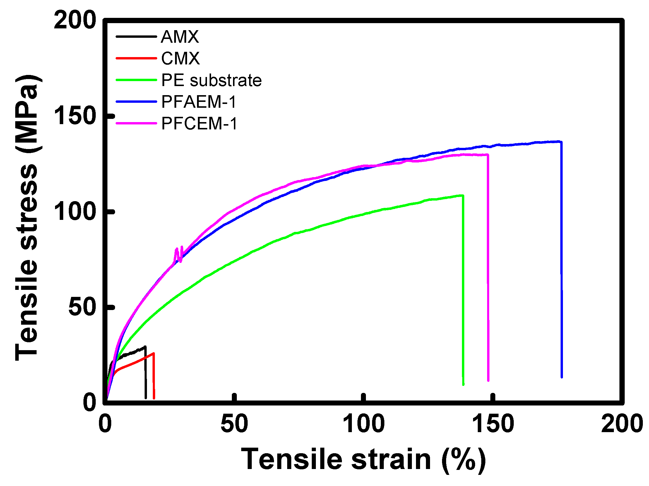
| Membrane | Thickness (μm) | Tensile Strength (MPa) | Elongation at Break (%) |
|---|---|---|---|
| AMX (Astom Corp.) | 140 | 29.47 | 15.60 |
| CMX (Astom Corp.) | 160 | 25.96 | 18.86 |
| Porous substrate | 25 | 108.5 | 138.4 |
| PFAEM-1 | 25 | 136.6 | 176.5 |
| PFCEM-1 | 25 | 129.9 | 148.0 |
| Membrane | Thickness (μm) | WU (%) | SR (%) | IEC (meq./g) | σ (mS/cm) | MER (Ω·cm2) | Transport Number (-) | Contact Angle (°) | (× 10−7, m/s) |
|---|---|---|---|---|---|---|---|---|---|
| AMX | 140 | 22.4 | 16.8 | 1.54 | 5.24 | 2.67 | 0.988 | 54.14 | 3.27 |
| PFAEM-0 | 25 | 23.8 | 20.7 | 2.02 | 3.97 | 0.63 | 0.988 | - | 2.17 |
| PFAEM-1 | 25 | 12.8 | 19.3 | 1.34 | 1.58 | 1.58 | 0.978 | 58.17 | 1.18 |
| PFAEM-2 | 25 | 14.8 | 20.0 | 1.67 | 1.87 | 1.34 | 0.985 | - | 2.57 |
| PFAEM-3 | 25 | 16.8 | 20.9 | 2.00 | 2.69 | 0.93 | 0.991 | - | 2.73 |
| CMX | 160 | 27.1 | 14.8 | 1.89 | 5.93 | 2.70 | 0.977 | 45.72 | 6.54 |
| PFCEM-0 | 25 | 17.1 | 12.7 | 2.26 | 4.31 | 0.58 | 0.991 | - | 3.97 |
| PFCEM-1 | 25 | 13.1 | 10.4 | 1.96 | 1.52 | 1.64 | 0.979 | 52.53 | 3.27 |
| PFCEM-2 | 25 | 15.7 | 15.1 | 2.47 | 1.82 | 1.37 | 0.983 | - | 4.47 |
| PFCEM-3 | 25 | 18.3 | 17.1 | 2.74 | 2.16 | 1.16 | 0.987 | - | 5.39 |
| Membrane | CE (%) | VE (%) | EE (%) |
|---|---|---|---|
| AMX | 92.6 | 93.2 | 86.2 |
| PFAEM-0 | 95.0 | 94.6 | 89.9 |
| PFAEM-1 | 96.4 | 93.2 | 89.9 |
| PFAEM-2 | 94.7 | 93.4 | 88.4 |
| PFAEM-3 | 93.3 | 94.4 | 88.0 |
| CMX | 90.9 | 91.3 | 83.0 |
| PFCEM-0 | 94.3 | 92.1 | 86.8 |
| PFCEM-1 | 94.8 | 92.3 | 87.6 |
| PFCEM-2 | 93.5 | 92.5 | 86.5 |
| PFCEM-3 | 92.4 | 93.5 | 86.3 |
| Membrane | Type | Company | CE (%) | VE (%) | EE (%) | Current Density (mA/cm2) | Ref. |
|---|---|---|---|---|---|---|---|
| Nafion 117 | CEM | DuPont | 85.7 | 92.5 | 79.3 | 30 | [54] |
| Nafion 212 | CEM | DuPont | 89.6 | 84.2 | 75.5 | 40 | [55] |
| NEPEM115 | CEM | Kerun | 88.6 | 85.7 | 78.5 | 60 | [11] |
| NR 212 | CEM | DuPont | 89.2 | 88.8 | 79.2 | 50 | [56] |
| N 115 | CEM | DuPont | 90.5 | 85.6 | 82.8 | 20 | [56] |
| FAP-PP-475 | AEM | Fumatech | 92.6 | 85.0 | 78.7 | 60 | [11] |
| FAP-PE-420 | AEM | Fumatech | 91.0 | 86.0 | 78.0 | 60 | [11] |
| APS | AEM | Asahi Glass | 89.3 | 87.0 | 77.7 | 60 | [11] |
Publisher’s Note: MDPI stays neutral with regard to jurisdictional claims in published maps and institutional affiliations. |
© 2021 by the authors. Licensee MDPI, Basel, Switzerland. This article is an open access article distributed under the terms and conditions of the Creative Commons Attribution (CC BY) license (https://creativecommons.org/licenses/by/4.0/).
Share and Cite
Moon, H.-N.; Song, H.-B.; Kang, M.-S. Thin Reinforced Ion-Exchange Membranes Containing Fluorine Moiety for All-Vanadium Redox Flow Battery. Membranes 2021, 11, 867. https://doi.org/10.3390/membranes11110867
Moon H-N, Song H-B, Kang M-S. Thin Reinforced Ion-Exchange Membranes Containing Fluorine Moiety for All-Vanadium Redox Flow Battery. Membranes. 2021; 11(11):867. https://doi.org/10.3390/membranes11110867
Chicago/Turabian StyleMoon, Ha-Neul, Hyeon-Bee Song, and Moon-Sung Kang. 2021. "Thin Reinforced Ion-Exchange Membranes Containing Fluorine Moiety for All-Vanadium Redox Flow Battery" Membranes 11, no. 11: 867. https://doi.org/10.3390/membranes11110867
APA StyleMoon, H.-N., Song, H.-B., & Kang, M.-S. (2021). Thin Reinforced Ion-Exchange Membranes Containing Fluorine Moiety for All-Vanadium Redox Flow Battery. Membranes, 11(11), 867. https://doi.org/10.3390/membranes11110867