Article

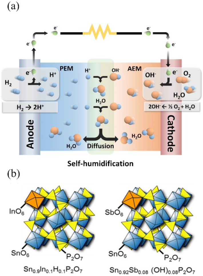
Self-Humidifying Membrane for High-Performance Fuel Cells Operating at Harsh Conditions: Heterojunction of Proton and Anion Exchange Membranes Composed of Acceptor-Doped SnP2O7 Composites

1
Fuel Cell Engineering Team, Hyundai Mobis, 37, Cheoldobangmulgwan-ro, Uiwang-si 16082, Korea
2
Department of Materials Engineering and Convergence Technology, Gyeongsang National University, Jinju 52828, Korea
*
Author to whom correspondence should be addressed.
Membranes 2021, 11(10), 776; https://doi.org/10.3390/membranes11100776
Submission received: 3 September 2021 / Revised: 27 September 2021 / Accepted: 5 October 2021 / Published: 11 October 2021
(This article belongs to the Special Issue Membranes in Electrochemistry Applications)

Abstract

:
Here we suggest a simple and novel method for the preparation of a high-performance self-humidifying fuel cell membrane operating at high temperature (>100 °C) and low humidity conditions (<30% RH). A self-humidifying membrane was effectively prepared by laminating together proton and anion exchange membranes composed of acceptor-doped SnP2O7 composites, Sn0.9In0.1H0.1P2O7/Sn0.92Sb0.08(OH)0.08P2O7. At the operating temperature of 100 °C, the electrochemical performances of the membrane electrode assembly (MEA) with this heterojunction membrane at 3.5% RH were better than or comparable to those of each MEA with only the proton or anion exchange membranes at 50% RH or higher.

1. Introduction

Polymer electrolyte membrane fuel cells (PEMFCs) have been intensively studied with the goal of commercialization [1,2,3]. An important issue that has recently emerged for the wide application of PEMFCs is to increase the operating temperature up to 120 °C while simultaneously decreasing the relative humidity (RH) below 30%, as suggested by the U.S. Department of Energy (DOE) [4,5]. However, commercially available perfluorosulfonic acid membranes (PFSAs), such as Nafion (Dupont Chemical, Wilgminton, DE, USA) and Aciplex (Asahi Chemical Inc., Osaka, Japan), cannot function as polymer electrolyte membranes under such harsh operating conditions because the absorbed water molecules facilitating the ion transportation are evaporated, leading to a significant decrease in the membrane conductivity [6]. To date, several promising membranes based on hydrocarbon polymers have been reported, such as polyether ether ketone (PEEK) [7], poly(arylene ether sulfone) (PAES) [8,9], polysulfone (PSf) [10], and polybenzimidazole (PBI) [11,12]. Among these membranes, the H3PO4-doped PBI membrane exhibits conductivities of ca. 10−2 S cm−1 above 100 °C and low RH condition. However, the use of a membrane electrode assembly employing the H3PO4-doped PBI membrane is problematic since some of the H3PO4 permeates into the cathode and poisons the Pt catalyst by the strong adsorption of phosphate anions [13].
As part of an alternative approach to the development of electrolyte membranes operating at high temperature and low RH condition, various composite membranes with self-humidification ability that can be prepared by simple methods have been proposed. Self-humidifying membranes are typically divided into three main types according to the materials incorporated in the membrane system: (1) Pt or Pt/C catalysts promote the reaction of hydrogen and oxygen from the anode and the cathode, respectively, to produce water in the membrane [14]; (2) hygroscopic metal oxides, such as SiO2 and TiO2, bound water molecules and maintain the hydration of the membrane [14,15]; and (3) proton-conductive materials, such as zirconium phosphate and heteropolyacids [16,17], improve the proton conducting behavior of the membrane at high temperature and low RH condition. However, although these types of membranes are useful for the harsh operating conditions of PEMFCs, they have some problems that remain unsolved: (1) the heterogeneous dispersion of Pt may lead to local electronic conduction throughout the membrane [18]; (2) the increase of the additive contents may lead to increase the ohmic resistance of the membrane [19]; (3) the poor compatibility between the additive and membrane may decrease the mechanical properties of the membrane [20].
These issues examine the heterojunction of proton and anion exchange membranes as a novel method for the development of self-humidifying membranes. When the two laminated membranes are arranged by placing the proton and anion exchange membranes at the anode and cathode sides, respectively, the following electrode reactions occur during cell discharge:
Anode: H2 → 2H+ + 2e
Cathode: 1/2O2 + H2O + 2e → 2OH
At the interface between the two membranes, it is proposed that the following reaction occurs, as shown in Figure 1a:
2H+ + 2OH → 2H2O
The resulting water product humidifies the two membranes, which improves their ionic conductivities at high temperature and low RH condition. The three problems noted above can essentially be avoided by using this technology, because it does not utilize any additives. An additional benefit of this method is the lower fabrication cost of the self-humidifying membrane, as the two membranes are simply pressed together.
In this work, acceptor-doped SnP2O7 is used as proton and anion exchange membranes because these compounds have high proton or hydroxide ion conductivity (>10−2 S cm−1) under the temperature range from 50 to 300 °C [21]. The SnP2O7 structures are characterized by the presence of intersecting zigzag tunnels delimited by pentagonal windows, which provide many ion exchangeable sites and conducting pathways [22]. The ion-exchange capabilities are incorporated into the bulk SnP2O7 through the partial substitution of Sn4+ cations with low valency In3+ and high valency Sb5+ due to the charge compensation of the dopant cations [18,19]. The optimal compositions of these acceptor-doped SnP2O7 compounds were determined to be Sn0.9In0.1H0.1P2O7 and Sn0.92Sb0.08(OH)0.08P2O7. Their crystalline structures are illustrated in Figure 1b. The self-humidification of the membrane during the fuel cell operation is demonstrated by electrical conductivity and water uptake measurements. Further, the self-humidification effect on the IR loss of the membrane during the operation is quantified through electrochemical measurements.

2. Experimental

2.1. Sample Preparation

The Sn0.9In0.1H0.1P2O7 and Sn0.92Sb0.08(OH)0.08P2O7 membranes were prepared by following the previously reported procedures [20,23]: briefly, SnO2 and In2O3 or Sb2O5 were mixed with a H3PO4 solution at a molar ratio of P/(Sn + In or + Sb) = 2. The solution mixture was stirred at 300 °C until a high viscosity paste was formed. Next the resulting paste was calcined in a crucible alumina pot at 650 °C for 2.5 h. Then, 0.04 g of polytetrafluoroethylene (PTFE) powder was added to 1.00 g of Sn0.9In0.1H0.1P2O7 or Sn0.92Sb0.08(OH)0.08P2O7 powder, kneaded using a mortar and pestle, and finally cold-rolled to a thickness of 200 μm using a rolling mill. The two membranes obtained in this way were laminated together by pressing at 2 MPa for 2 min. For comparison, Sn0.9In0.1H0.1P2O7 and Sn0.92Sb0.08(OH)0.08P2O7 membranes with thicknesses of 400 μm were also prepared.

2.2. Fabrication of Hydrogen/Air Fuel Cell

Commercialized Pt/C electrode (0.5 cm2, Electrochem Inc., Woburn, MA, USA) with a Pt loading of 1 mg cm−2 was used for the preparation of the membrane electrode assembly (MEA), and the MEA was fabricated by sandwiching the electrolyte membrane between the electrodes. Two gas chambers were arranged by placing the MEA between two alumina tubes and sealing the anode side of the MEA with an inorganic adhesive. Unless otherwise stated, unhumidified hydrogen (50 mL min−1) and air (50 mL min−1) saturated by H2O vapor at room temperature were respectively supplied to the anode and cathode. The fuel cell was operated between 50 and 200 °C.

2.3. Characterization

The water uptake of the electrolyte membrane was calculated as follows. Prior to water uptake measurements, the fuel cell was operated with a current density of 80 mA cm−2 at 100 °C for 1 h. Then, part of the electrolyte membrane was immediately removed from the MEA and a thermogravimetric analysis (TGA; Shimadzu, DTG-60, Kyoto, Japan) was conducted from room temperature to 300 °C under air with a heating rate of 10 °C min−1. AC conductivity measurements of the electrolyte membrane were performed under the fuel cell operating conditions. Impedance spectra were collected using an impedance analyzer (Solartron, SI 1260, Farnborough, UK) and an electrochemical interface (Solartron, 1287, Farnborough, UK) in the frequency range from 10–106 Hz with an AC amplitude of 10 mV. The IR loss of the MEA was determined using the current interruption method. During the measurement, a sharp change in voltage and a slow voltage change indicate IR loss and polarization loss, respectively. A digital oscilloscope (Nicolet, Sigma 75, Gainesville, FL, USA) was used to monitor the change in cell voltage over time.

3. Results and Discussion

The temperature dependency of the electrical conductivity for the Sn0.9In0.1H0.1P2O7/Sn0.92Sb0.08(OH)0.08P2O7 membrane is presented in Figure 2a. For comparison, the conductivities of the individual Sn0.9In0.1H0.1P2O7 and Sn0.92Sb0.08(OH)0.08P2O7 membranes were also included. The measurement was conducted under open-circuit conditions at the operating temperatures between 50 and 200 °C in air saturated with H2O vapor at room temperature. The conductivity of these membranes does not follow the Arrhenius-like dependency on temperature, because the RH decreases with increasing temperature (PH2O rather than RH was maintained constantly at the measurement). However, the electrical conductivity of the heterojunction (i.e., Sn0.9In0.1H0.1P2O7/Sn0.92Sb0.08(OH)0.08P2O7) membrane was comparable to those of the Sn0.9In0.1H0.1P2O7 and Sn0.92Sb0.08(OH)0.08P2O7 membranes within the experimental error at all tested temperatures, which implies the absence of an insulating layer at the interface of the heterojunction membrane due to the high compatibility between the Sn0.9In0.1H0.1P2O7 and Sn0.92Sb0.08(OH)0.08P2O7 membranes. A similar conclusion has been reported regarding the heterojunction electrolyte composed of proton-conductive yttrium-doped strontium zirconia and oxide ion-conductive yttria-stabilized zirconia [24].
The PH2O and RH dependency of the electrical conductivity for the Sn0.9In0.1H0.1P2O7/Sn0.92Sb0.08(OH)0.08P2O7 membrane at 50, 100, and 200 °C were also evaluated under open-circuit conditions (Figure 2b,c). Although the electrical conductivity increased with increasing PH2O at all tested temperatures, the PH2O dependency of the electrical conductivity was the largest at 100 °C. This result can be interpreted to mean the following: since the membrane is highly hygroscopic at 50 °C, high electrical conductivity is maintained even under low RH conditions. However, the evaporation of water from the membrane is significant at 200 °C, thus reducing the humidification effect on the electrical conductivity. These results suggest that the most effective temperature for the self-humidification of the fuel cell is around 100 °C. Therefore, in subsequent experiments, the fuel cell was operated at 100 °C.
To observe the water product accumulated in the Sn0.9In0.1H0.1P2O7/Sn0.92Sb0.08(OH)0.08P2O7 membrane during the operation, the membranes were pressed against clean paper before and after operation (Figure 3a,b). Figure 3b clearly shows that the membrane contained a certain quantity of water after the operation that had changed compared to the quantity before the operation. Although care should be taken to account for water adsorbed on the membrane surface during cell operation, this result indicates that the observed polka-dot trace shown in Figure 3b is mainly attributable to water produced by the self-humidification effect of the membrane. Such traces are substantially less visible when using the individual Sn0.9In0.1H0.1P2O7 and Sn0.92Sb0.08(OH)0.08P2O7 membranes as electrolytes.
Further evidence of self-humidification is confirmed by a comparison of TGA profiles for Sn0.9In0.1H0.1P2O7/Sn0.92Sb0.08(OH)0.08P2O7 and the individual Sn0.9In0.1H0.1P2O7 or Sn0.92Sb0.08(OH)0.08P2O7 membranes after cell operation. Figure 3c shows that the individual Sn0.9In0.1H0.1P2O7 and Sn0.92Sb0.08(OH)0.08P2O7 membranes have similar TGA profiles: A weight loss of ca. 4% occurred in two steps between 50 and 300 °C by the desorption of physically and chemically observed water molecules, respectively [25,26]. Meanwhile the weight loss of the Sn0.9In0.1H0.1P2O7/Sn0.92Sb0.08(OH)0.08P2O7 membrane is approximately two times larger than that observed for the individual Sn0.9In0.1H0.1P2O7 and Sn0.92Sb0.08(OH)0.08P2O7 membranes. This result indicates that the increased weight loss is caused by the water produced at the heterojunction, according to Equation (3), then accumulated in the membrane.
If this suggestion is correct, then a decrease in the ohmic resistance or the IR loss of the Sn0.9In0.1H0.1P2O7/Sn0.92Sb0.08(OH)0.08P2O7 membrane would be expected as a result of the operation of the fuel cell because the water produced by self-humidification increases the electrical conductivity. For clarification, electrochemical measurements were conducted. Figure 4 presents the impedance spectra of the fuel cell under open-circuit and DC bias (0.3 V) voltages conditions. The ohmic resistance of the cell with the Sn0.9In0.1H0.1P2O7/Sn0.92Sb0.08(OH)0.08P2O7 membrane was reduced by applying a DC bias voltage (Figure 4a), in contrast to the impedance spectra for the fuel cells with the individual Sn0.9In0.1H0.1P2O7 and Sn0.92Sb0.08(OH)0.08P2O7 membranes (Figure 4b,c). The ohmic resistances of the cells with the Sn0.9In0.1H0.1P2O7 and Sn0.92Sb0.08(OH)0.08P2O7 membranes remained almost unchanged, despite the fact that polarization of the fuel cells was conducted.
Figure 5a presents the IR losses of the fuel cell over time with a current density of 80 mA cm−2 applied to the fuel cells. The IR loss decreased with time until a steady state was reached. The fuel cell with the Sn0.9In0.1H0.1P2O7/Sn0.92Sb0.08(OH)0.08P2O7 membrane shows a decrement in IR loss with time, while those with the individual Sn0.9In0.1H0.1P2O7 and Sn0.92Sb0.08(OH)0.08P2O7 membranes are shown to be unchanged during the same period. These results support the self-humidification of the Sn0.9In0.1H0.1P2O7/Sn0.92Sb0.08(OH)0.08P2O7 membrane. In addition, the result of the Sn0.9In0.1H0.1P2O7/Sn0.92Sb0.08(OH)0.08P2O7 membrane also reflects an increase in water uptake with time, and the results imply that it takes approximately 7 min to reach an equilibrium of water uptake into the membrane.
Figure 5b presents the IR loss of the fuel cells as a function of the current density, where data were recorded after steady state was attained. The IR loss of the fuel cell with the Sn0.9In0.1H0.1P2O7/Sn0.92Sb0.08(OH)0.08P2O7 membrane deviated from that estimated (dotted line) from the electrical conductivity at 100 °C, the extent of which increased as the current density increased due to the enhanced self-humidification effect. By contrast, the IR losses of the fuel cells with the individual Sn0.9In0.1H0.1P2O7 and Sn0.92Sb0.08(OH)0.08P2O7 membranes almost coincided with the estimated values.
To clarify the self-humidification effect during the fuel cell performance, the IR losses of the fuel cells with the individual Sn0.9In0.1H0.1P2O7 and Sn0.92Sb0.08(OH)0.08P2O7 membranes with different PH2O conditions from 0.035 to 0.690 atm were measured and compared with those of the Sn0.9In0.1H0.1P2O7/Sn0.92Sb0.08(OH)0.08P2O7 membrane at a PH2O of 0.035 atm (Figure 6a,b). A comparison between the fuel cells with the Sn0.9In0.1H0.1P2O7/Sn0.92Sb0.08(OH)0.08P2O7 and individual Sn0.9In0.1H0.1P2O7 or Sn0.92Sb0.08(OH)0.08P2O7 membranes confirmed that the IR loss of the former membrane at a PH2O of 0.035 atm was equivalent to that of the latter two membranes at PH2O between 0.465 and 0.690 atm, indicating that the present heterojunction fuel cell can successfully enhance the electrolyte properties without the need for external humidification.

4. Conclusions

A self-humidifying fuel cell membrane showing the outstanding electrochemical performances at the harsh operating conditions of high temperature and low RH was simply prepared by laminating the proton and anion exchange membranes composed of acceptor-doped SnP2O7 composites. The effect of the heterojunction membrane (Sn0.9In0.1H0.1P2O7/Sn0.92Sb0.08(OH)0.08P2O7) on the electrolyte properties was investigated. Since the insulating layer was not formed at the interface between the Sn0.9In0.1H0.1P2O7 and Sn0.92Sb0.08(OH)0.08P2O7 membranes, the water absorption of the membrane increased during the fuel cell operation. The comparison of TGA thermograms of the membranes indicated that the water content of the heterojunction membrane was approximately two times larger than the individual Sn0.9In0.1H0.1P2O7 and Sn0.92Sb0.08(OH)0.08P2O7 membranes. Therefore, the electrochemical performances of MEAs performance with the heterojunction membrane were substantially better than those with each proton and anion exchange membranes under low RH condition. For example, the IR losses of the heterojunction membrane at current densities of 80 and 120 mA cm−2 after equilibrium state at 100 °C are 105 and 157 mV, respectively, while those of the Sn0.9In0.1H0.1P2O7 membrane are 183 and 226 mV, respectively, and those of the Sn0.92Sb0.08(OH)0.08P2O7 membranes are 177 and 246 mV, respectively. Based on the results, we believe that this study can provide insight into the facile preparation of a self-humidifying heterojunction membrane and the wide use of acceptor-doped SnP2O7 composites for practical application in high temperature and low RH fuel cells.

Author Contributions

Conceptualization: P.H., K.K.; data curation and investigation: P.H., M.K. and H.K.; formal analysis: P.H., M.K., H.K., S.Y.N., K.K.; funding acquisition: S.Y.N., K.K.; supervision: K.K.; visualization: P.H., M.K., H.K., K.K.; writing—original draft preparation, P.H. and M.K., H.K., S.Y.N., K.K. All authors have read and agreed to the published version of the manuscript.

Funding

This research was supported by the National Research Foundation of Korea funded by the Korean Government (NRF-2019M3E6A1064797, NRF-2019R1F1A1060550, NRF-2020R1A6A1A03038697).

Institutional Review Board Statement

Not applicable.

Informed Consent Statement

Not applicable.

Conflicts of Interest

The authors certify that there is no conflict of interest with any organization regarding the subject matter or materials discussed in the manuscript.

References

  1. Peighambardoust, S.J.; Rowshanzamir, S.; Amjadi, M. Review of the proton exchange membranes for fuel cell applications. Int. J. Hydrog. Energy 2010, 35, 9349–9384. [Google Scholar] [CrossRef]
  2. Goñi-Urtiaga, A.; Presvytes, D.; Scott, K. Solid acids as electrolyte materials for proton exchange membrane (PEM) electrolysis. Int. J. Hydrog. Energy 2012, 37, 3358–3372. [Google Scholar] [CrossRef]
  3. Kim, K.; Heo, P.; Ko, T.; Lee, J.-C. Semi-interpenetrating network electrolyte membranes based on sulfonated poly (arylene ether sulfone) for fuel cells at high temperature and low humidity conditions. Electrochem. Commun. 2014, 48, 44–48. [Google Scholar] [CrossRef]
  4. Marcinkoski, J.; Kopasz, J.P.; Benjamin, T.G. Progress in the US DOE fuel cell subprogram efforts in polymer electrolyte fuel cells. Int. J. Hydrog. Energy 2008, 33, 3894–3902. [Google Scholar] [CrossRef]
  5. Kim, K.; Choi, S.-W.; Park, J.O.; Kim, S.-K.; Lim, M.-Y.; Kim, K.-H.; Ko, T.; Lee, J.-C. Proton conductive cross-linked benzoxazine-benzimidazole copolymers as novel porous substrates for reinforced pore-filling membranes in fuel cells operating at high temperatures. J. Membr. Sci. 2017, 536, 76–85. [Google Scholar]
  6. Kim, K.; Heo, P.; Ko, T.; Kim, K.-h.; Kim, S.-K.; Pak, C.; Lee, J.-C. Poly (arlyene ether sulfone) based semi-interpenetrating polymer network membranes containing cross-linked poly (vinyl phosphonic acid) chains for fuel cell applications at high temperature and low humidity conditions. J. Power Sources 2015, 293, 539–547. [Google Scholar] [CrossRef]
  7. Lee, H.; Han, J.; Ahn, S.M.; Jeong, H.Y.; Kim, J.; Kim, H.; Kim, T.-H.; Kim, K.; Lee, J.-C. Simple and effective cross-linking technology for the preparation of cross-linked membranes composed of highly sulfonated poly (ether ether ketone) and poly (arylene ether sulfone) for fuel cell applications. J. ACS Appl. Energy Mater. 2020, 3, 10495–10505. [Google Scholar] [CrossRef]
  8. Han, J.; Lee, H.; Kim, J.; Kim, S.; Kim, H.; Kim, E.; Sung, Y.-E.; Kim, K.; Lee, J.-C. Sulfonated poly (arylene ether sulfone) composite membrane having sulfonated polytriazole grafted graphene oxide for high-performance proton exchange membrane fuel cells. J. Membr. Sci. 2020, 612, 118428. [Google Scholar] [CrossRef]
  9. Han, J.; Kim, K.; Kim, J.; Kim, S.; Choi, S.-W.; Lee, H.; Kim, J.-j.; Kim, T.-H.; Sung, Y.-E.; Lee, J.-C. Cross-linked highly sulfonated poly (arylene ether sulfone) membranes prepared by in-situ casting and thiol-ene click reaction for fuel cell application. J. Membr. Sci. 2019, 579, 70–78. [Google Scholar] [CrossRef]
  10. Kim, K.; Jung, B.-K.; Ko, T.; Kim, T.-H.; Lee, J.-C. Comb-shaped polysulfones containing sulfonated polytriazole side chains for proton exchange membranes. J. Membr. Sci. 2018, 554, 232–243. [Google Scholar] [CrossRef]
  11. Kim, J.; Kim, K.; Ko, T.; Han, J.; Lee, J.-C. Polybenzimidazole composite membranes containing imidazole functionalized graphene oxide showing high proton conductivity and improved physicochemical properties. Int. J. Hydrog. Energy 2021, 46, 12254–12262. [Google Scholar] [CrossRef]
  12. Kim, J.H.; Kim, K.; Nam, S.Y. Research Trends of Polybenzimidazole-based Membranes for Hydrogen Purification Applications. Appl. Chem. Eng. 2020, 31, 453–466. [Google Scholar]
  13. Zelenay, P.; Scharifker, B.; Bockris, J.M.; Gervasio, D. A Comparison of the Properties of CF 3 SO 3 H and H 3 PO 4 in Relation to Fuel Cells. J. Electrochem. Soc. 1986, 133, 2262. [Google Scholar] [CrossRef]
  14. Watanabe, M.; Uchida, H.; Seki, Y.; Emori, M.; Stonehart, P. Self-humidifying polymer electrolyte membranes for fuel cells. J. Electrochem. Soc. 1996, 143, 3847. [Google Scholar] [CrossRef]
  15. Amjadi, M.; Rowshanzamir, S.; Peighambardoust, S.; Hosseini, M.; Eikani, M. Investigation of physical properties and cell performance of Nafion/TiO2 nanocomposite membranes for high temperature PEM fuel cells. Int. J. Hydrog. Energy 2010, 35, 9252–9260. [Google Scholar] [CrossRef]
  16. Zhang, H.; Zhu, B.; Xu, Y. Composite membranes of sulfonated poly (phthalazinone ether ketone) doped with 12-phosphotungstic acid (H3PW12O40) for proton exchange membranes. Solid State Ion. 2006, 177, 1123–1128. [Google Scholar] [CrossRef]
  17. Lee, H.-K.; Kim, J.-I.; Park, J.-H.; Lee, T.-H. A study on self-humidifying PEMFC using Pt–ZrP–Nafion composite membrane. Electrochim. Acta 2004, 50, 761–768. [Google Scholar] [CrossRef]
  18. Liang, H.; Dang, D.; Xiong, W.; Song, H.; Liao, S. High-performance self-humidifying membrane electrode assembly prepared by simultaneously adding inorganic and organic hygroscopic materials to the anode catalyst layer. J. Power Sources 2013, 241, 367–372. [Google Scholar] [CrossRef]
  19. Liang, H.; Zheng, L.; Liao, S. Self-humidifying membrane electrode assembly prepared by adding PVA as hygroscopic agent in anode catalyst layer. Int. J. Hydrog. Energy 2012, 37, 12860–12867. [Google Scholar] [CrossRef]
  20. Su, H.; Xu, L.; Zhu, H.; Wu, Y.; Yang, L.; Liao, S.; Song, H.; Liang, Z.; Birss, V. Self-humidification of a PEM fuel cell using a novel Pt/SiO2/C anode catalyst. Int. J. Hydrog. Energy 2010, 35, 7874–7880. [Google Scholar] [CrossRef]
  21. Heo, P.; Ito, K.; Tomita, A.; Hibino, T. A Proton-Conducting Fuel Cell Operating with Hydrocarbon Fuels. Angew. Chem. 2008, 120, 7959–7962. [Google Scholar] [CrossRef]
  22. Jin, Y.; Shen, Y.; Hibino, T. Proton conduction in metal pyrophosphates (MP2O7) at intermediate temperatures. J. Mater. Chem. 2010, 20, 6214–6217. [Google Scholar] [CrossRef]
  23. Hibino, T.; Shen, Y.; Nishida, M.; Nagao, M. Hydroxide Ion Conducting Antimony (V)-Doped Tin Pyrophosphate Electrolyte for Intermediate-Temperature Alkaline Fuel Cells. Angew. Chem. 2012, 124, 10944–10948. [Google Scholar] [CrossRef]
  24. Shimura, T.; Egusa, G.; Iwahara, H.; Katahira, K.; Yamamoto, K. Electrochemical properties of junction between protonic conductor and oxide ion conductor. Solid State Ion. 1997, 97, 477–482. [Google Scholar] [CrossRef]
  25. Kim, K.; Kim, S.-K.; Park, J.O.; Choi, S.-W.; Kim, K.-H.; Ko, T.; Pak, C.; Lee, J.-C. Highly reinforced pore-filling membranes based on sulfonated poly (arylene ether sulfone) s for high-temperature/low-humidity polymer electrolyte membrane fuel cells. J. Membr. Sci. 2017, 537, 11–21. [Google Scholar] [CrossRef]
  26. Hickner, M.A.; Ghassemi, H.; Kim, Y.S.; Einsla, B.R.; McGrath, J.E. Alternative polymer systems for proton exchange membranes (PEMs). Chem. Rev. 2004, 104, 4587–4612. [Google Scholar] [CrossRef]
Figure 1. (a) schematic diagram of self-humidifying heterojunction membrane fuel cell and (b) crystalline structure of Sn0.9In0.1H0.1P2O7 and Sn0.92Sb0.08(OH)0.08P2O7.
Membranes 11 00776 g001
Figure 2. (a) Temperature dependency of electrical conductivity for Sn0.9In0.1H0.1P2O7, Sn0.92Sb0.08(OH)0.08P2O7, and Sn0.9In0.1H0.1P2O7/Sn0.92Sb0.08(OH)0.08P2O7 membranes. The measurement was conducted under open-circuit conditions at operating temperatures (50–200 °C) in air saturated with H2O vapor at room temperature. (b) PH2O and (c) RH dependency of electrical conductivity for Sn0.9In0.1H0.1P2O7/Sn0.92Sb0.08(OH)0.08P2O7 membrane.
Membranes 11 00776 g002
Figure 3. Photo images of water transfer from Sn0.9In0.1H0.1P2O7/Sn0.92Sb0.08(OH)0.08P2O7 membrane to clean paper; (a) before and (b) after fuel cell operation. Dotted circle lines indicate change of clean paper by produced water after pressing the membranes. (c) TGA profiles of membranes.
Membranes 11 00776 g003
Figure 4. Impedance spectra for (a) Sn0.9In0.1H0.1P2O7/Sn0.92Sb0.08(OH)0.08P2O7 (b) Sn0.9In0.1H0.1P2O7 and (c) Sn0.92Sb0.08(OH)0.08P2O7 membranes under open-circuit and DC bias (0.3 V) conditions.
Membranes 11 00776 g004
Figure 5. Change in IR losses for Sn0.9In0.1H0.1P2O7, Sn0.92Sb0.08(OH)0.08P2O7, and Sn0.9In0.1H0.1P2O7/Sn0.92Sb0.08(OH)0.08P2O7 membranes with respect to (a) time and (b) current density. The cells were operated at 100 °C with unhumidified H2 and air saturated with H2O vapor at room temperature (PH2O = 0.035 atm) as reactor gases for anode and cathode, respectively.
Membranes 11 00776 g005
Figure 6. IR losses at different PH2O conditions of (a) Sn0.9In0.1H0.1P2O7 and (b) Sn0.92Sb0.08(OH)0.08P2O7 membranes as a function of current density. Red circle lines indicate IR losses of Sn0.9In0.1H0.1P2O7/Sn0.92Sb0.08(OH)0.08P2O7 membrane at a PH2O of 0.035 atm.
Membranes 11 00776 g006
Publisher’s Note: MDPI stays neutral with regard to jurisdictional claims in published maps and institutional affiliations.

