Review

Metal and Covalent Organic Frameworks for Membrane Applications

Institut Européen des Membranes—IEM UMR 5635, Univ Montpellier, CNRS, ENSCM, 34095 Montpellier, France
*
Authors to whom correspondence should be addressed.
Present address: Departamento de Química Inorgánica, Universidad Autónoma de Madrid, 28049 Madrid, Spain.
Membranes 2020, 10(5), 107; https://doi.org/10.3390/membranes10050107
Submission received: 28 April 2020 / Accepted: 19 May 2020 / Published: 22 May 2020
(This article belongs to the Special Issue Membranes: 10th Anniversary)

Abstract

:
Better and more efficient membranes are needed to face imminent and future scientific, technological and societal challenges. New materials endowed with enhanced properties are required for the preparation of such membranes. Metal and Covalent Organic Frameworks (MOFs and COFs) are a new class of crystalline porous materials with large surface area, tuneable pore size, structure, and functionality, making them a perfect candidate for membrane applications. In recent years an enormous number of articles have been published on the use of MOFs and COFs in preparation of membranes for various applications. This review gathers the work reported on the synthesis and preparation of membranes containing MOFs and COFs in the last 10 years. Here we give an overview on membranes and their use in separation technology, discussing the essential factors in their synthesis as well as their limitations. A full detailed summary of the preparation and characterization methods used for MOF and COF membranes is given. Finally, applications of these membranes in gas and liquid separation as well as fuel cells are discussed. This review is aimed at both experts in the field and newcomers, including students at both undergraduate and postgraduate levels, who would like to learn about preparation of membranes from crystalline porous materials.

1. Introduction

Membranes could be found in nearly all areas of science and technology since their development is destined to solve problems related to aging population, emerging developing countries, pollution, environmental remediation, and more efficient industrial production to name a few. The wide use of this type of materials in industry is due to the fact that membrane separation processes are more energy-efficient and it does not involve any phase transformation.
According to the International Union of Pure and Applied Chemistry (IUPAC) a membrane is “a structure that has lateral dimensions much greater than its thickness, through which transfer may occur under a variety of driving forces” [1] This definition may sound similar to the concept of thin-film but in this case, IUPAC defines thin-film as “a film whose thickness is of the order of a characteristic scale or smaller” [2]. The difference between a membrane and a thin-film is that a membrane is a thin, film-like structure (not necessarily a solid) that separates fluids (liquids, gases, or vapours), acting as a selective barrier, allowing specific substances to pass through, while retaining others. In contrast, due to the mechanical properties of the thin films, they must be placed on a substrate and does not necessarily fulfil the same function; instead it can be part of a membrane as in the thin-film composite (TFC) membranes.
Membranes can be classified according to different criteria: nature, morphology, bulk structure, geometry configuration as well as the size of the separated particles [3,4]. Commonly the membranes are grouped into biological or synthetic membranes. While biological membranes are within or around a cell in a living organism, recognising what is necessary for the cell to receive or block for its survival, synthetic membranes are at the heart of a wide range of key industries such as food, biotechnology, electronics, and energy. They can be produced from organic material such as polymers (polyvinylidene fluoride (PVDF), polyamide, polyimide, etc.) or from inorganic materials like metal oxides and ceramics. An ideal membrane should present the following industrial requirements: (1) be as thin as possible with good mechanical properties to lower energy consumption and cost; (2) show high pore density to maximize the membrane porosity and thus the flux and permeability; (3) be selective due to a controlled morphology at the nanometre scale; (4) use a universal preparation strategy providing a broad range of pore sizes with a sharp control especially between 1 and 100 nm; (5) good chemical and thermal stability and; (6) have tuneable dynamics to afford in-situ control over membrane parameters (pore size, flux, etc.) [5].
Currently, most of the commercial membranes are based on polymeric materials due to their high processability into viable membrane structures and the diverse polymers available, as well as the capability to synthesising novel polymer structures. Nevertheless, polymers present some limitations related to their low thermal and chemical stabilities, low selectivity, and short lifetimes. In this sense, inorganic membranes show higher stabilities and can feature perfectly ordered pores but the range of pore size accessible is restricted and exhibits rather small surface areas. So, given the huge quantity of membrane applications, it is of high interest to explore new nanostructured materials with specific properties and morphologies to offer powerful tools for the preparation of membranes with improved features to existing ones. Membrane-based separation used to be dominated by the porosity of the material so it is a key factor to take into account during the search for new alternative materials [6]. Therefore, attention of the scientific community must be in porous materials that are solids containing empty voids, which can host other molecules.
Over the past decade, interest in the field of porous materials has grown tremendously because of their outstanding performance and broad applications in gas storage and separation, heterogeneous catalysis, energy, optoelectronics, sensing, and drug delivery. Chemists have found ways to prepare a wide variety of porous materials; however, the synthesis of porous frameworks with discrete pores has proven to be difficult until the inception of the concept of reticular chemistry, which uses topologically, designed organic, and inorganic building blocks linked by strong bonds to make crystalline open frameworks [7,8,9,10]. Metal-Organic Frameworks (MOFs) [11,12] and Covalent-Organic Frameworks (COFs) [13] are two kinds of crystalline porous materials obtained applying this chemistry. MOFs materials are constructed from a metal ion or a cluster of metal ions and an organic linker or bridging ligands through strong coordination bonds [14]. To date, more than 60,000 MOFs with different compositions, crystal structures, and morphologies have been reported due to the possibility of wide variation of metal ions and organic linker combinations [15,16]. On the other hand, COFs are inspired from MOFs and synthesised via reversible strong covalent bonds between light elements such as boron, carbon, nitrogen, and oxygen [7,17,18]. Pure organic components of COFs give them lower density and better compatibility with other organic materials. But both crystalline porous materials are characterised by permanent porosities with very high surface areas, high thermal stabilities, and exceptional chemical stabilities in organic and aqueous media, acids, and bases. Functionality and utility of these structures are often enhanced over those obtained from polymeric materials; due to their much better-defined pore structures with narrower size distribution, increased pore stability, and the tuneable pore sizes depending on the dimensions of the building blocks used. These properties make them both excellent candidates for many applications in fields of gas storage [19], catalysis [20,21], electrochemistry [22], gas separation [23], sensors [24,25,26], and medicine [27], among others. Most of these applications require that the material be previously processed. In this regard, very recently Zamora and coworkers have discussed the strategies used for COF processability [28]. As it can be seen in Figure 1, in the last decade there has been an almost exponential growth in the number of papers published on MOF and COF membranes. This is due to the enormous progress made in the use of MOF and COF in the separation processes using membranes. To date several reviews on MOF membranes have been published focusing on their general and specific applications [29,30,31,32,33,34]. In the case of COF, there is only one review by Van der Bruggen based specifically on COF membranes for separation applications [35]. Very recently, Xu and coworkers have published a review on the preparation of ultrathin MOF and COF membranes for separation applications [36]. Apart from this review, there are no comprehensive reports gathering the work performed on both COF and MOF membranes for membrane applications. In this regard, we collect the work reported on MOF and COF membranes in this manuscript, so that it serves as a base for researchers new to the subject as well as a quick update for the experts in the field.
This review is divided into three parts. In the first part, the most conventional methods used in the preparation of MOF and COF membranes including free-standing membranes, thin-film composite (TFC) membranes, MOF/COF composites membranes, and mixed matrix membranes (MMMs) are gathered. In the second part the main characterisation techniques used to determine membrane properties are discussed. Moreover, unexplored and potential characterisation techniques that could be used for such membranes are introduced. Finally, the most recent and relevant reports on MOF and COF membranes for gas separation (CO2 recovery, H2 purification and recovery, and hydrocarbon separation), liquid separation (water treatment, organic solvent nanofiltration, and separation of small molecules in liquid mixtures), and in fuel cells are described. From our point of view, this review would serve as a good starting point to learn about the use of MOF and COF material in membrane science.

2. Preparation Methods

The fabrication of membranes free of pinhole defects, grain edge defects, inter-crystalline, and intra-crystalline cracks are a major challenge. This section reviews the methods used for the preparation of MOF and COF membranes including thin-film composite membranes, MOF-COF composite membranes and mixed matrix membranes based on MOFs and COFs.

2.1. MOF Membranes

MOF membrane preparation is quite similar to that used for zeolites. Indeed, the majority of MOF membranes reported since the first report in 2009 [37], are based on zeolite imidazolate frameworks (ZIFs) because of their zeolite-like structure and properties such as high thermal and chemical stability, permanent porosity, and tuneable pore sizes [23,38]. However, due to their poor mechanical stability, there are not many examples of free-standing MOF membranes and most of them are prepared on inorganic or polymeric porous supports with different shapes depending on the final application. Here, we collect the main methods used for MOF membrane preparation accompanied by some recent examples. For readers interested in large scale MOF membrane preparation there is an interesting recent review published by Li [29].

2.1.1. In Situ Growth

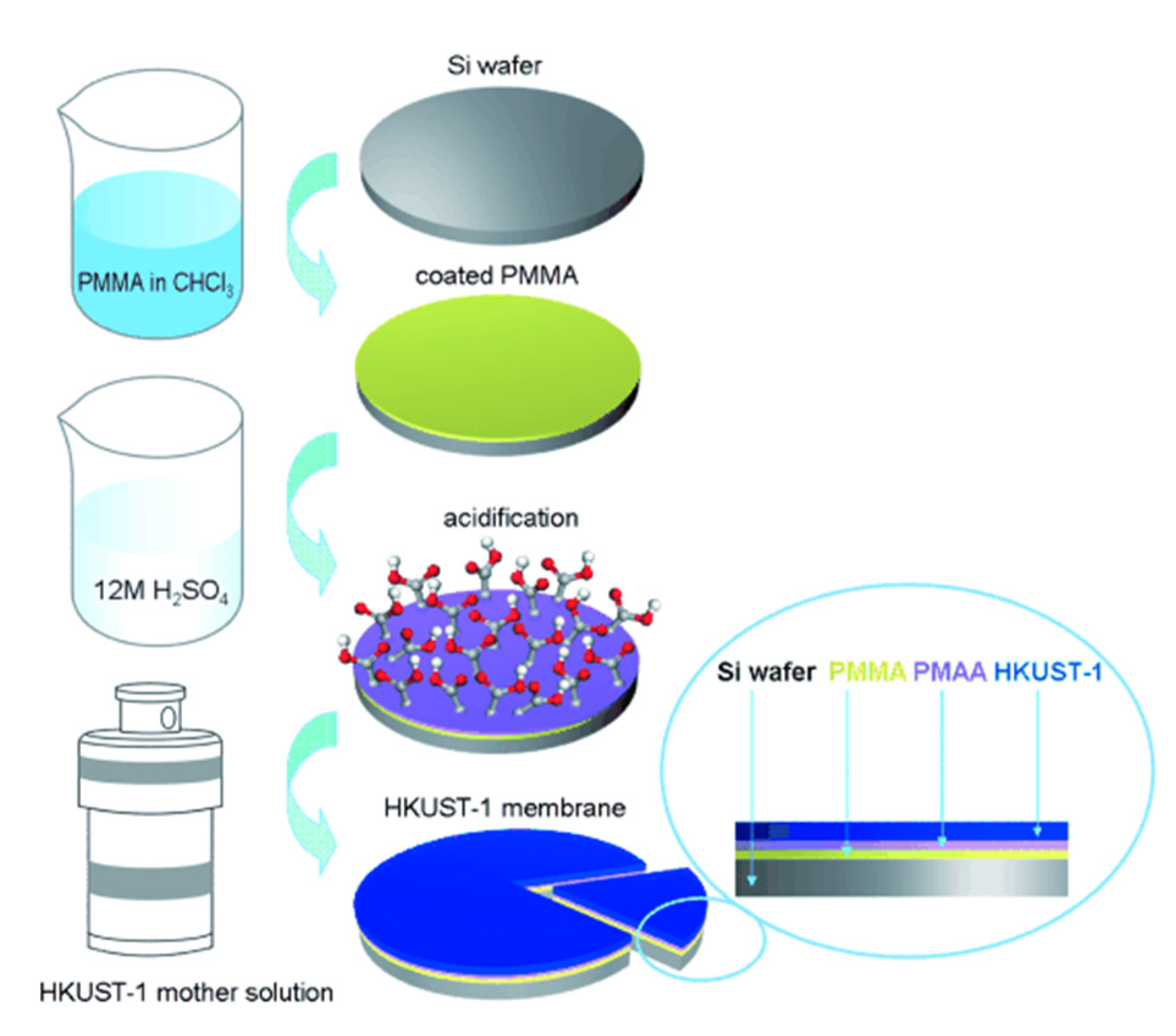
In situ or direct growth method is a well-known strategy for the preparation of thin-film MOF membranes. It consists of the immersion of a porous substrate, usually Al2O3 or TiO2, in the precursors solution in which nucleation and heterogeneous crystal growth occurs after the solvothermal, hydrothermal, or microwave treatment applied [39,40]. In order to increase the adhesion of the MOF layers to the substrate, some approaches related to the support surface modification have been tested. For example, Caro and coworkers succeeded in the preparation of thin-film MOF membranes through the surface functionalisation with 3-aminopropyltriethoxysilane (APTES) [41,42] and polydopamine (PDA) [43,44], which acted as covalent linkers between the MOF and the porous substrate. Ben et al. reported a method for the preparation of free-standing MOF membranes with tuneable thickness, from the chemical modification of the surface substrate with poly(methyl methacrylate) (PMMA), which is converted in poly(methacrylic acid) (PMAA) for facilitating the MOF nucleation. Then, the solution of the PMMA-PMAA-coated surface results in the release of the MOF membrane (Figure 2) tested in gas separation [45]. The support surface can also be modified with the same organic linker used for the MOF synthesis as was already demonstrated by McCarthy et al. who grafted imidazolate ligands to α-Al2O3 supports before growing the ZIF crystals [46].
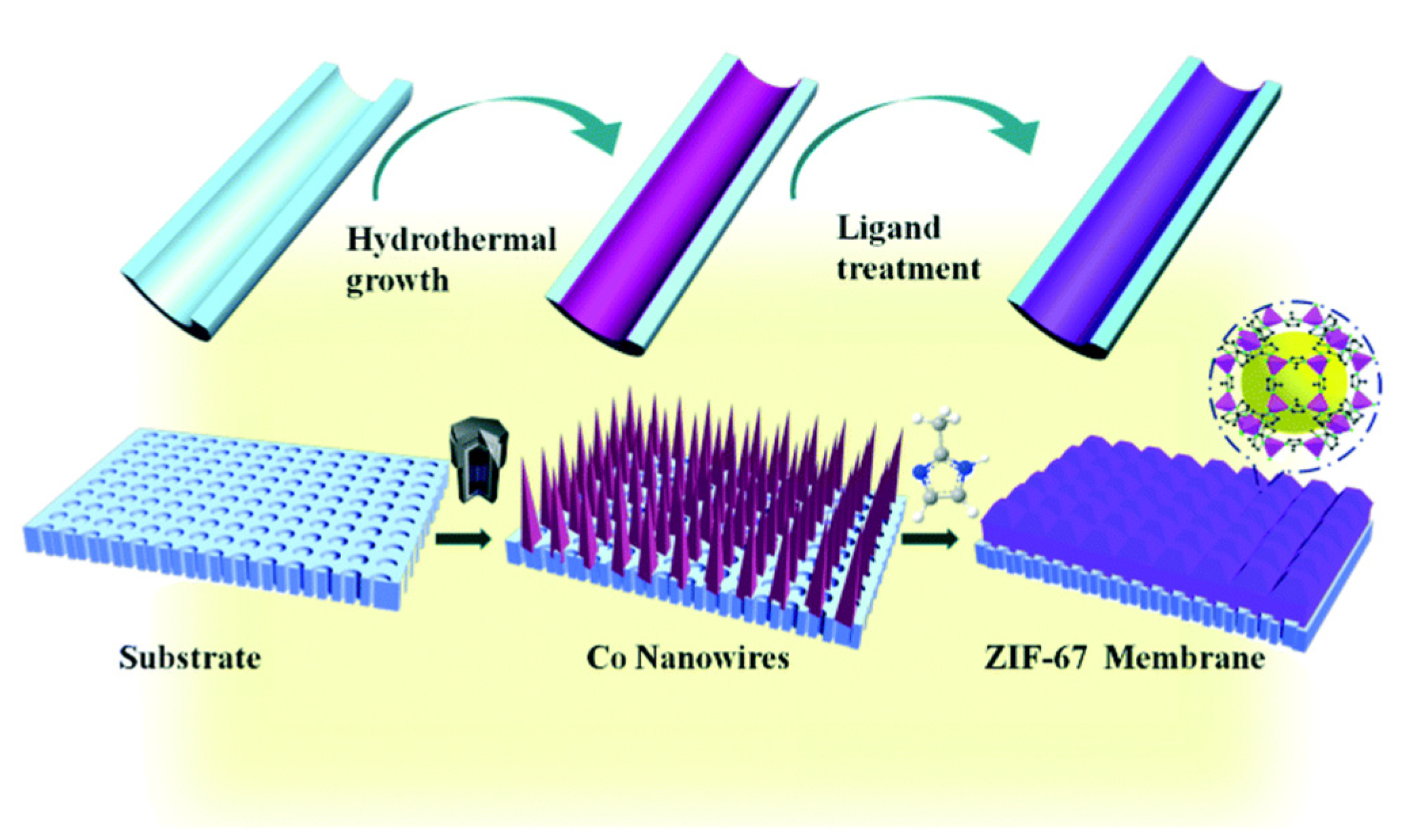
Other in situ growth approaches involve the use of a metal surface both as a substrate to support the membrane as well as to act as an ions source for the MOF synthesis [47,48,49,50]. Using the same principle, a metal oxide layer like ZnO can be deposited on a porous support in order to provide active sites prior to the Zn-based MOF membrane formation [51,52]. Recently, Zhang and coworkers showed the preparation of a Co-based ZIF membrane (1.7 μm thickness) on a porous tubular support after the direct transformation of carbonate hydroxide nanowire arrays (Co-NWAs) in a 2-methylimidazole (Hmim) aqueous solution (Figure 3) for H2 separation [53].

2.1.2. Seeded Assisted or Secondary Growth

This method allows a better control of the membrane microstructure in terms of nucleation and crystal growth, giving rise to the formation of compact, continuous and thin polycrystalline membranes. Basically, it consists of two steps: (i) seeding support with crystal seeds of the MOF and (ii) growing the crystals up. The first step is crucial for preparing well-intergrown polycrystalline membranes due to a homogeneous nucleation. So, it is very important to have control over the size, amount, location, and orientation of the crystal seeds since it will have influence on the membrane performance [54,55,56,57]. Sun et al. demonstrated the impact of the crystal orientation on gas separation by the preparation of the highly c-oriented NH2-MIL-125 membrane with a thickness of 200 nm [57]. Some of the most common techniques used to carry out the seeding method are rubbing [58], dip and spin-coating [54], electrospinning [59], electrospray [60], and layer-by-layer [61].
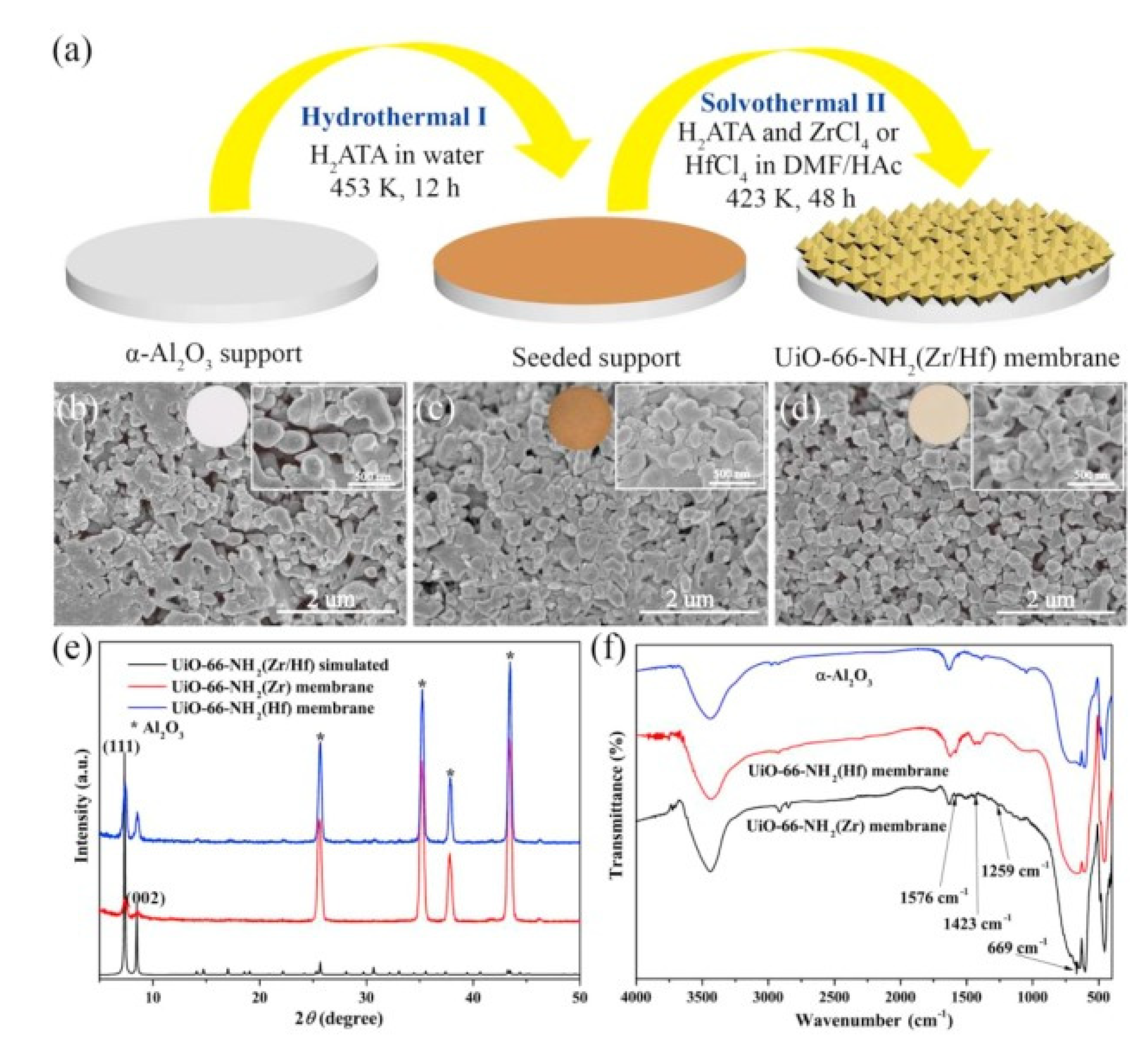
Alternately, Lee and coworkers developed a reactive seeding (RS) method for the preparation of continuous MOF membranes on porous alumina supports. As in the in situ growth, in the first step of this approach, the support acts as the inorganic source reacting with the organic precursor to grow the seed layer, which will help the formation of a superior MOF membrane in the secondary growth [62]. This method was further used by Du et al. for fabrication of a uniform, thin, and well intergrown UiO-66-NH2(Zr/Hf) MOF membrane (8 μm of thickness) with application in wastewater treatment. In this case, the process started with a uniform seeding layer growth on the support from the reaction between H2ATA and α-Al2O3 under hydrothermal conditions. At a later step, the UiO-66-NH2(Zr) membrane or UiO-66-NH2(Hf) membrane were prepared from the reaction between 2-aminoterephthalic acid (H2ATA) and ZrCl4 or HfCl4 in the mixed solution of N’N-dimethylformamide and acetic acid under solvothermal conditions. After this second step, the yellow colour indicated the formation of the membrane active layer (Figure 4) [63].

2.1.3. Layer-by-Layer Assembly

Layer-by-layer, also known as the step-by-step approach was thoroughly studied by Shekhah et al. for thin-film MOF formation [64]. This method is based on the sequential deposition of organic ligands and metal-oxo coupling units. After each step, the unreacted components were removed by solvent rinsing. One of the most important advantages of the layer-by-layer approach is the possibility to control the thickness of the growing film. Later, the same group applied this method for preparation of a ultrathin (0.5–1 µm) defect-free ZIF-8 membrane on alumina support and used it for separation of mixed gases [65]. Other authors also grew ZIF-8 on different supports applying the layer-by-layer concept but with slight modifications in the preparation method depending on the final application. For example, Kargari and coworkers placed the poly(phenyl sulfone) (PPSU) support at the bottom of a vessel and then soaked alternately with the salt and the organic solutions, the thickness of the ZIF-8 layer can reach about 10 µm per cycle of growth [66]. Very recently, Yang et al. obtained a high-quality ZIF-8 membrane ideal for gas separation, using the layer-by-layer deposition approach with the solvent-free crystallisation method followed by the in-situ heat treatment [67]. Tham et al. adapted this method for the preparation of a Zn benzene-1,4-dicarboxylic acid (Zn(BDC)) MOF on a chemically modified polyacrylonitrile (PAN) membrane using water as the sole solvent. The obtained membrane exhibited good performance in organic solvent nanofiltration (OSN) [68].

2.1.4. Contra-Diffusion or Interfacial Method

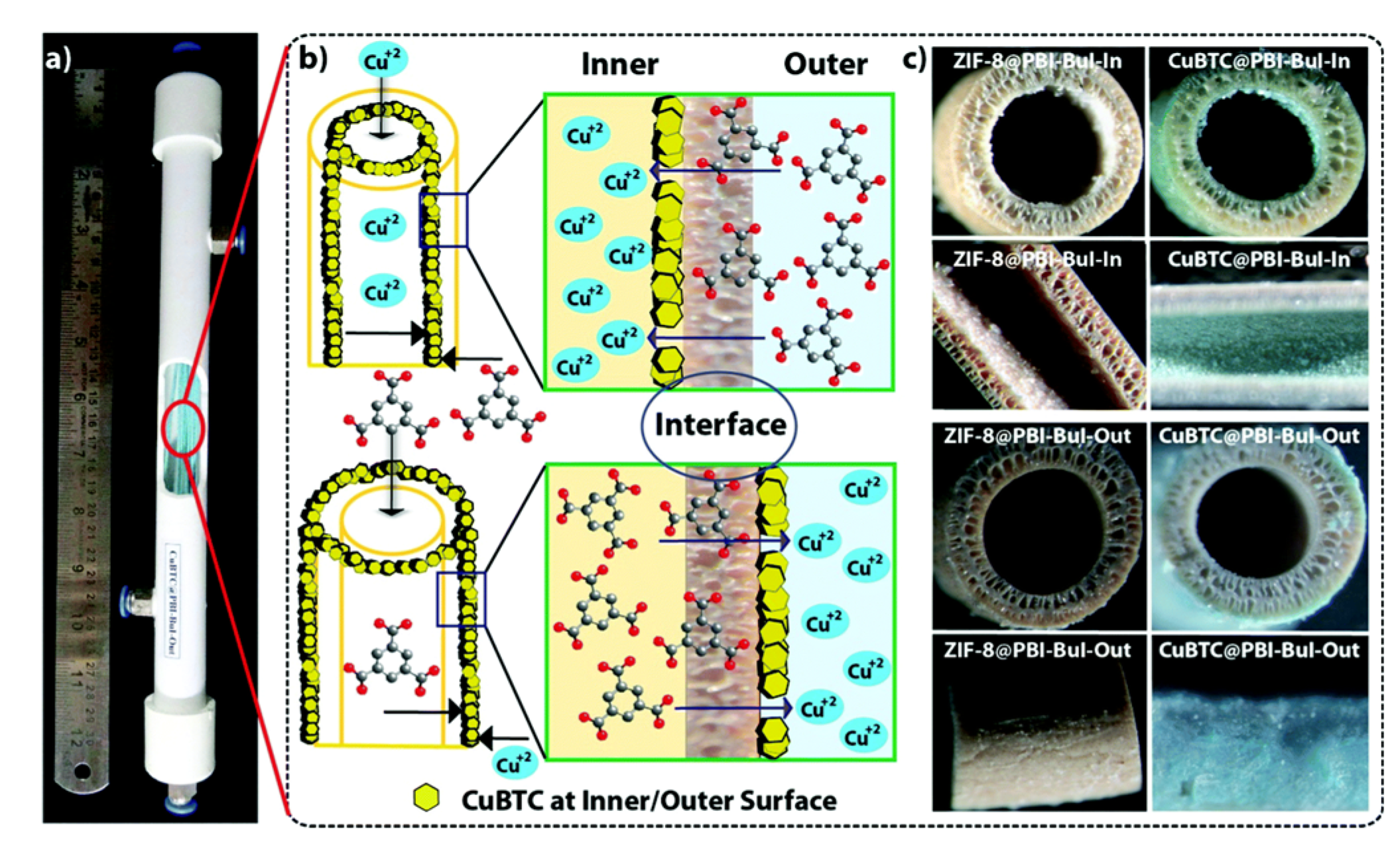
In 2011 Yao et al. developed this new approach to prepare ZIF-8 films with thickness’ up to 16 µm on a nylon substrate [69]. The method consists of placing the porous substrate between both the metal ion and the organic ligand solution. So, after the slow diffusion of both reagents through the substrate, crystallisation takes place on the membrane surface. Huang et al. used the contra-diffusion method to synthesise a ZIF-71 membrane (2.5 µm of thickness) on an inorganic hollow fibre substrate, ideal for the separation of ethanol–water mixtures [70]. In a similar approach, Biswal et al. showed a scalable method for growing MOFs (ZIF-8 and CuBTC) on either the outer or inner surface of a polybenzimidazole based hollow fibre (PBI-BuI-HF) membrane ideal for gas separation (Figure 5) [71].

2.1.5. Vapour Deposition

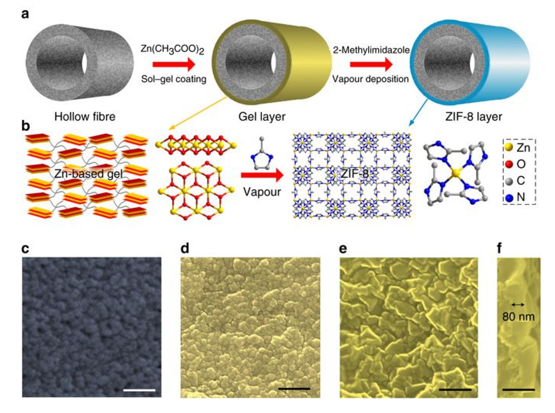
Vapour deposition techniques such as gel vapour deposition (GVD) and ligand-induced permselectivation (LIPS) have been used for the preparation of ultrathin MOF membranes. These innovative methods usually are characterised by being simple, reproducible, and scalable. GVD is based on the combination of a modification-free sol–gel coating and solvent-free vapour deposition [72]. Using this approach, Zeng and coworkers got to prepare a MOF membrane module (30 polymeric hollow fibres with a membrane area of 340 cm2) without deterioration in selectivity (Figure 6). Li et al. prepared a nanometre-thick ZIF-8 membrane through GVD with excellent gas separation performance [73].
Tsapatsis and coworkers used LIPS to transform an impermeable layer of ZnO obtained by atomic layer deposition (ALD) and deposited on an alumina support in a ZIF-8 membrane that was tested for hydrocarbon separation [74]. In a similar approach, Zhang and coworkers prepared a 2D Co-ZIF nanosheet membrane on a porous tubular substrate via LIPS with major improvement in H2/CO2 separation [75].

2.2. COF Membranes

The following part focuses on COF membrane preparation methods. Due to the organic COF nature, the methods explored are very similar to the one used for polymeric membrane preparation.

2.2.1. In Situ Growth

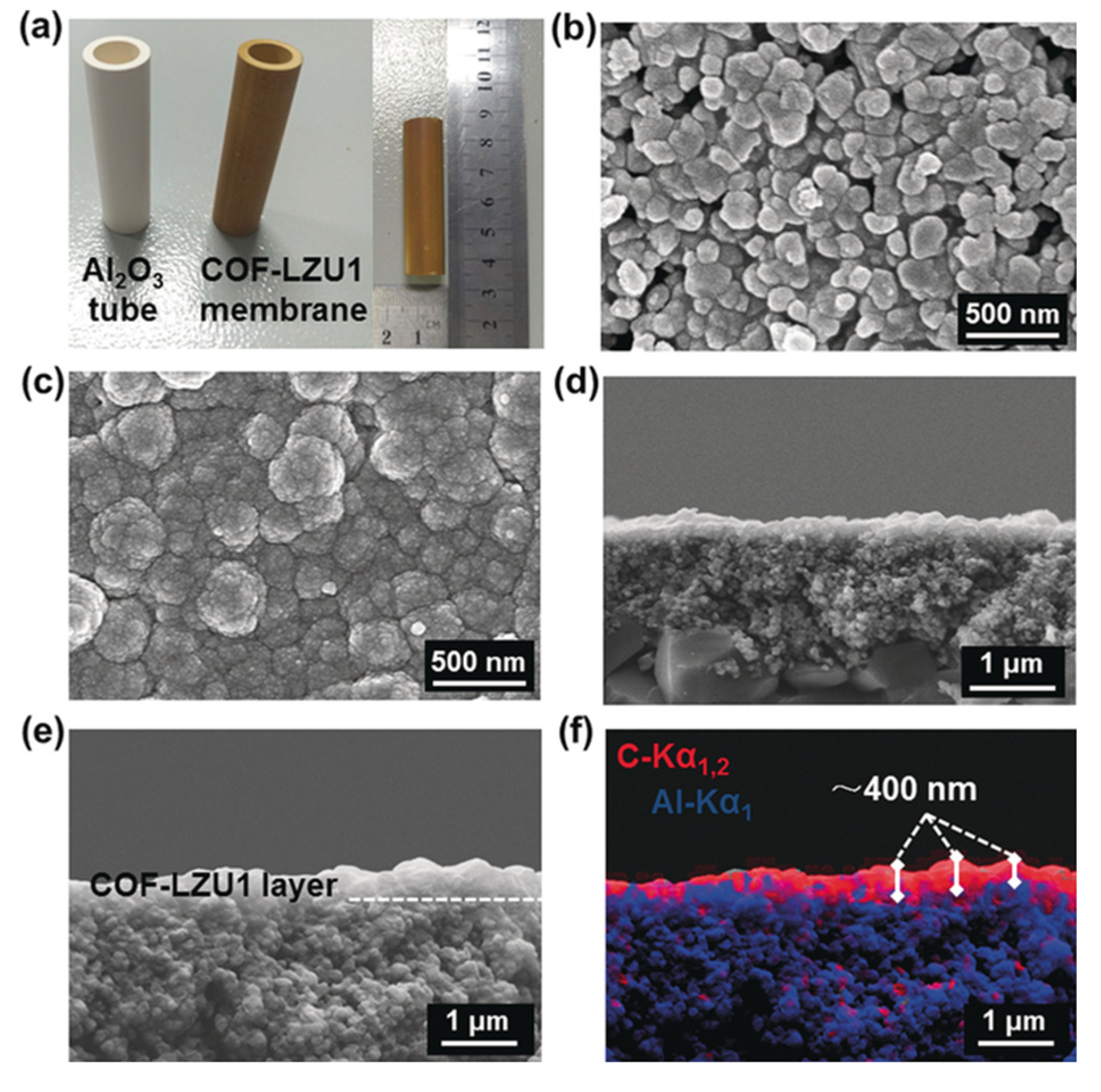
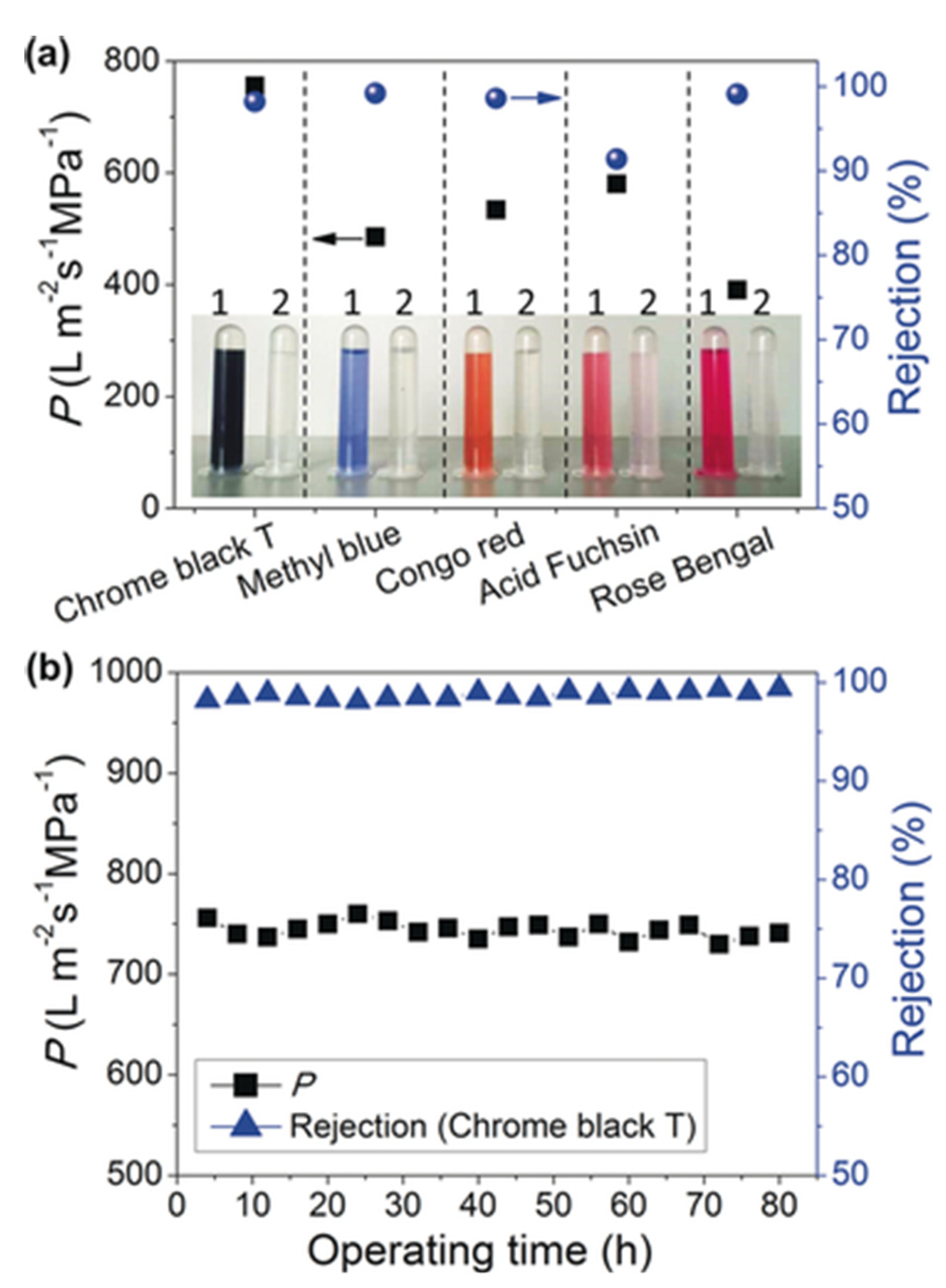
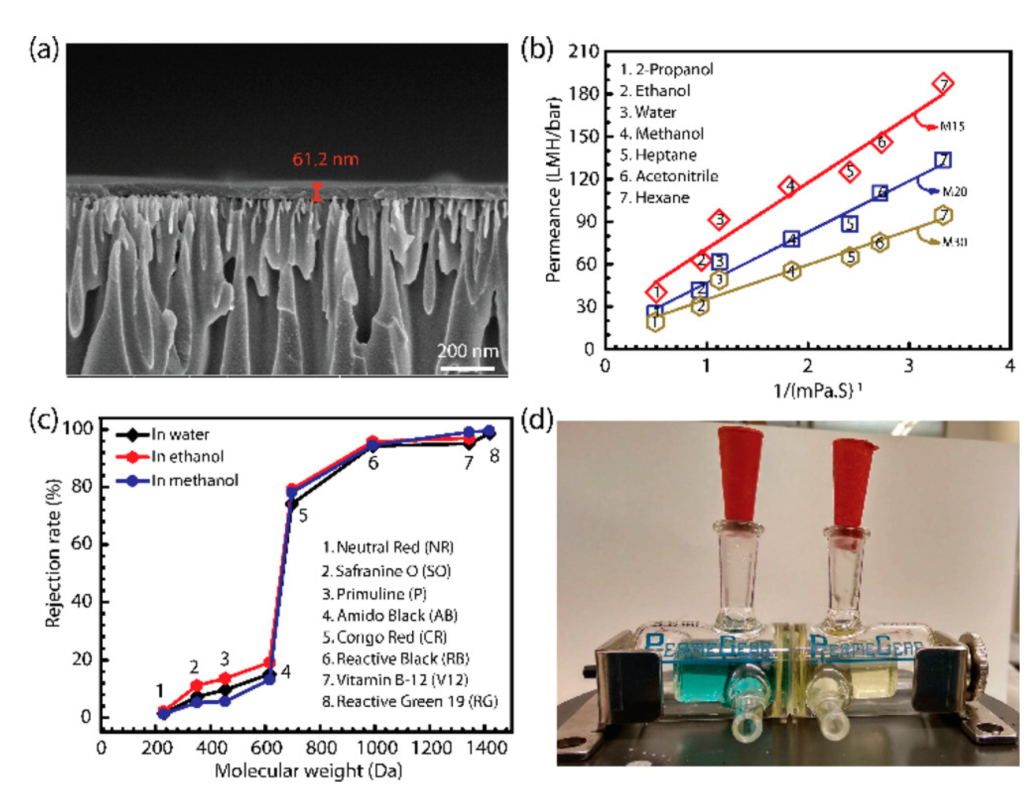
Using the in situ growth method, Gao and coworkers prepared for the first time a 3D COF membrane on a porous α-Al2O3, improving their previous results on COF-5 membrane preparation [76,77]. Specifically, the surface functionalisation of the α-Al2O3 facilitated the adhesion of the COF to the support by the imine condensation reaction between the amino groups of APTES and the aldehyde groups of the monomer during the solvothermal reaction. The resulting compact, uniform, and well-intergrown 3D COF-320 membrane had a thickness of about 4 µm. Caro and coworkers prepared a continuous and defect-free 2D imine-linked COF-LZU1 membrane (thickness of only 400 nm) on the outer modified surface of alumina tubes using in situ solvothermal synthesis. The robust membrane obtained, showed excellent water permeability as well as reasonable rejection rates (above 90%) for dye molecules (Figure 7) [78].

2.2.2. Solution Casting

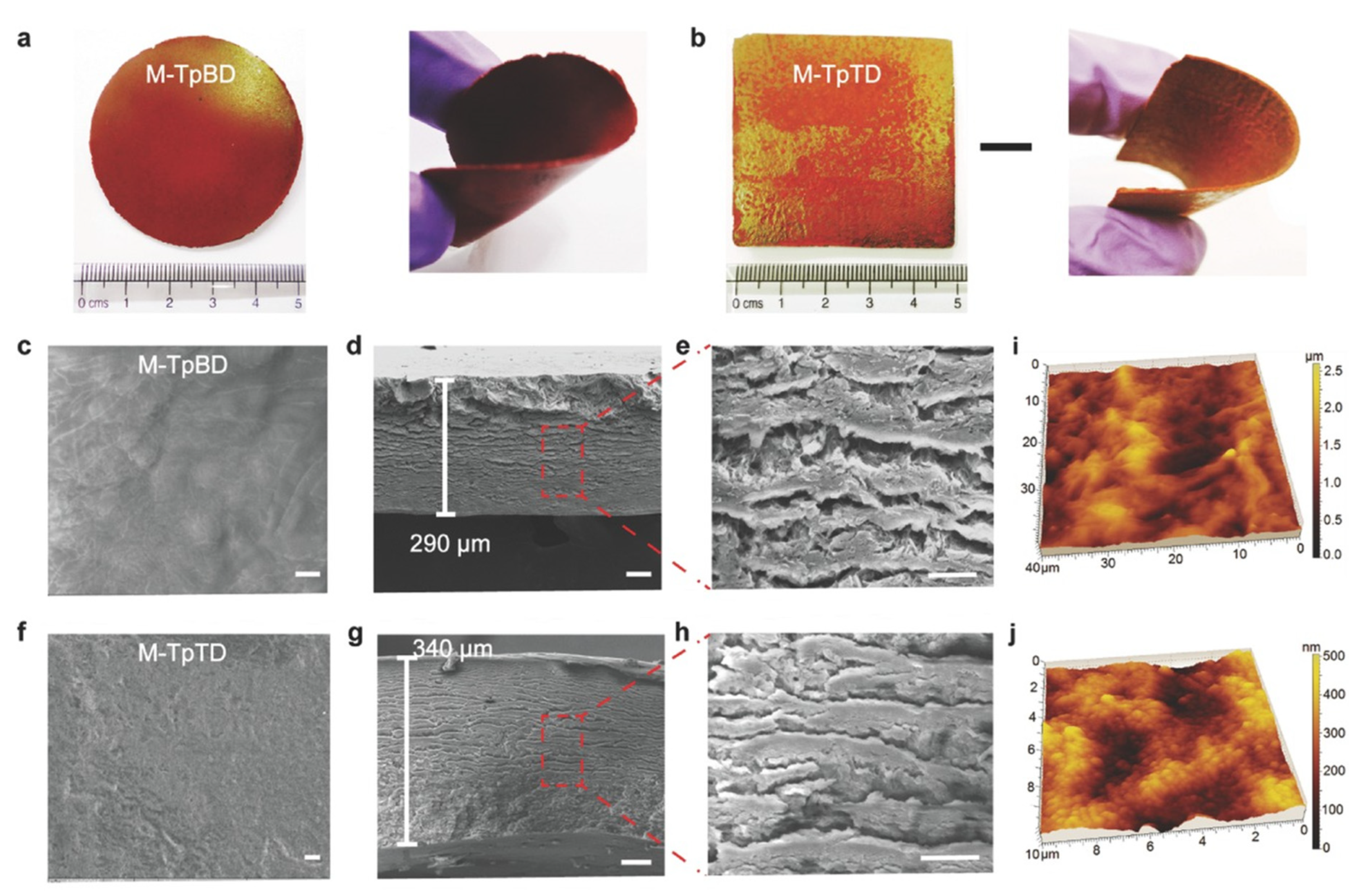
Banerjee et al. developed a new methodology for the fabrication of free-standing, flexible, and highly porous COF membranes based on ketoenamine COFs (Figure 8). This cost effective and highly scalable procedure consists of baking the reagent dough that previously had been knife-casted onto a glass plate. The obtained defect- and crack-free COF membrane, with a thickness ranging from 200 to 700 µm, was tested for selective molecular sieving [79]. Using a similar approach, the same group prepared three different COF membranes with a thickness > 100 µm by the slow baking of symmetrical organic linkers in the presence of amino p-toluene sulfonic acid (PTSA·H2O) and water at moderate temperature for three to four days. In this case, the co-reagent PTSA·H2O, besides improving both the porosity and the crystallinity of the membranes, it acted as a proton transporter resulting in high values of proton conductivity [80].

2.2.3. Layer-by-Layer Assembly

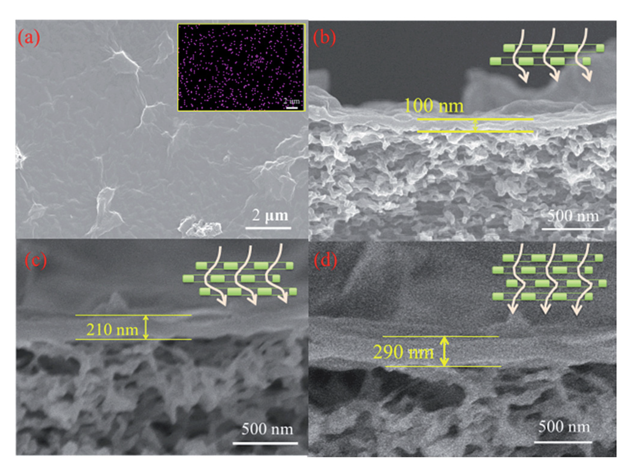
Layer-by-layer assembly is also a promising bottom-up strategy for the preparation of ultrathin COF membranes. This approach is based on the deposition of 2D nanomaterials with nanosheet morphology, which can act as building blocks for membrane construction. For example, Li et al. used a solution of COF-1 nanosheets for coating a macroporous α-Al2O3 substrate with a thin SiO2–ZrO2 intermediate layer to obtain a membrane free of crack and pinholes with an extremely permeable performance [81]. Yin et al. were pioneered in the preparation of ultrathin (<300 nm) COF membranes from a mixture of covalent triazine-based framework-1 (CTF-1) and graphene oxide (GO) nanosheets in water, which was restacked by filtration. The interactions between the functional groups in GO and the COF sheets led to the formation of continuous and dense ultrathin membranes (Figure 9) [82]. A similar approach was reported by Tang et al. for preparation of a defect free TpPa/GO membrane for H2/CO2 separation [83].
The deposition of the layer on the support can also be carried out by spin-coating. Pan and coworkers fabricated a dual-layer by the spin-coating of a 2D COF layer on a porous hydrolysed polyacrylonitrile (HPAN) substrate, which was spin coated with bio-inspired calcium alginate (Alg-Ca) layer. The double functionality of this membrane allowed, on one hand, to increase the adsorption of water molecules and, on the other, to serve as a molecular sieve in the alcohol dehydration process due to the structure of the COF [84].

2.2.4. Interfacial Polymerisation (IP)

This technique is very useful for the preparation of polymer thin films like polyamides and polyesters in the bulk scale [85,86]. It consists of the reaction of the monomers at the liquid–liquid interface. So, the diffusion of each of the monomers from the immiscible phase (usually aqueous and organic) will lead to the formation of free-standing thin-films. This layer can be deposited onto a porous substrate giving rise to a thin-film composite (TFC). The main benefits of this technique are related to its scalability and its capacity to produce thin separating active layers (<250 nm) with relatively high water permeability [87]. However, the amorphous nature of polymers makes the obtained TFC lack ordered, tuneable pore structures, which could be resolved with the use of crystalline materials. Pioneer work by Dey et al. used the IP strategy to prepare different TFCs based on free-standing imine-based COF films with permanent microporosity. For this, they decreased the diffusion rate at the interface by using amine-p-toluene sulfonic acid (PTSA) salt instead of free amine [88]. Mariñas and coworkers used IP for the preparation of a polyimine COF TFC nanofiltration membrane but in this case, both monomers were dissolved into the organic phase whereas the aqueous solution contained the catalyst [89]. Dichtel et al. used also IP to prepare TAPB-PDA COF free-standing membrane with large-area (several cm2) and tuneable thickness (2.5 nm to 100 mm) via changing the initial monomer concentration. This COF films could be easily transferred onto polyethersulfone supports and showed enhanced rejection of Rhodamine WT, a model water contaminant [90].
Alternatively, Wang and coworkers developed a new strategy based on IP that allows the fabrication of the COF selective layer directly on a support. This approach avoids the tedious transference of the thin-film layer onto the support surface as well as the long reaction times [91].

2.2.5. Langmuir−Blodgett (LB) Method

Langmuir−Blodgett (LB) is a potential method for preparing membrane with controllable thickness and large dimensions that can be easily transferred to different support surfaces. Lai et al. were pioneers in the preparation of a crystalline TFP-DHF 2D COF membrane using this method. They spread a solution of the two monomers in toluene on the surface of water. After complete evaporation of the solvent, the surface layer was compressed and trifluoroacetic acid was added dropwise. Finally, a continuous and yellow TFP-DHF-COF thin-film was formed on the water−air interface. These thin film layers were transformed to different supports for membrane application [92].

2.3. COF-MOF Composite Membranes

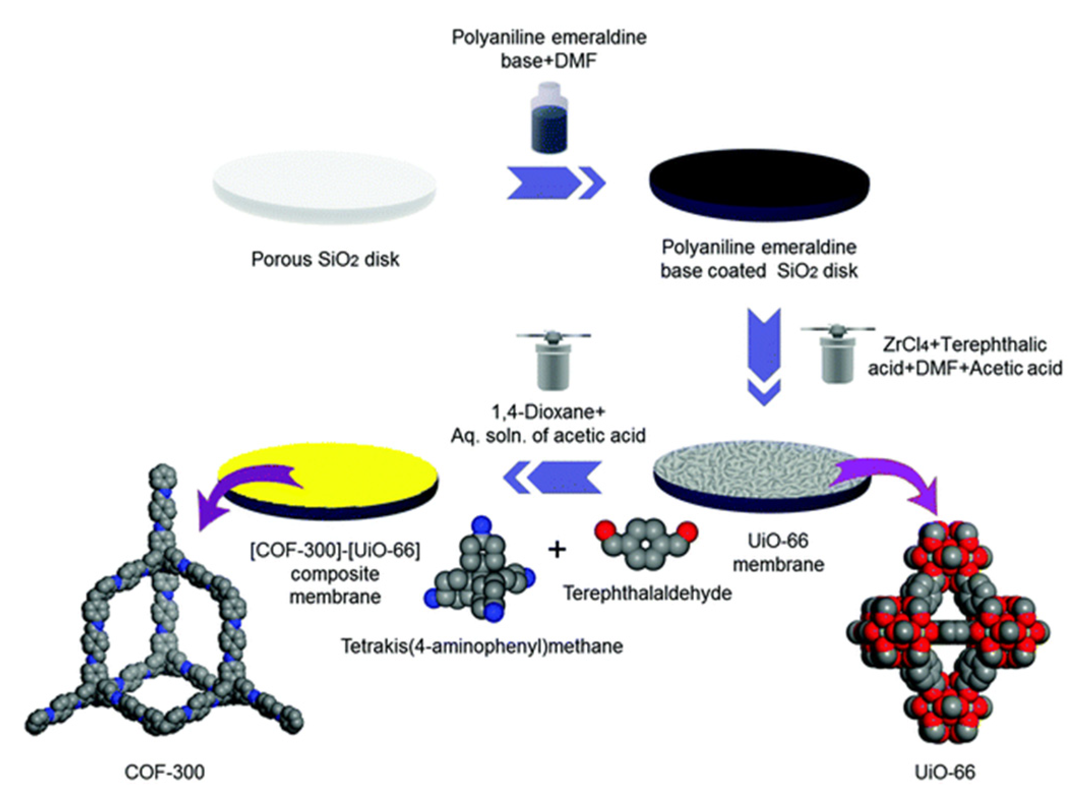
Considering the molecular sieving properties of MOFs and COFs, Fu et al. fabricated novel COF-MOF composite membranes with high performance in gas separation. Specifically, these membranes were prepared by the application of two consecutive in-situ growth methods. One for the synthesis of COF-300 on a modified polyaniline porous SiO2 and the second one for growing ZIF-8 or Zn2(bdc)2(dabco) MOFs using the COF-300 membrane as support. MOF and COF layers were adhered due to both zinc cation with the amine group and hydrogen interactions [93]. Following a similar approach, the same group prepared a [COF-300]-[UiO-66] composite membrane, which showed good performance in H2/CO2 separation (Figure 10) [94].

2.4. Mixed Matrix Membranes (MMMs) Based on MOFs and COFs

Another typical strategy for the preparation of MOF and COF membranes consists of the use of these materials as porous fillers in polymer matrices to form “mixed matrix membranes” (MMMs) also called hybrid membranes [95,96]. The advantage of using MMMs is that they combine the benefits of the mechanical strength and good processability of polymeric materials with the properties of the filler. According to Kitao et al. depending on the morphology, MMMs can be classified as symmetric or asymmetric membranes. While the first group is characterised by an uniform structure of filler and polymer, the second one is based on a thin and selective filler–polymer layer supported on a nonselective porous substrate [97,98,99].
The symmetric MMMs preparation method usually consists of the casting of a solution of the filler particles and the polymer mixture on a flat surface, with the help of a knife or doctor blade followed by an evaporation step (Figure 11). In order to avoid particle agglomeration and remove air bubbles stirring or sonication is used before casting. Moreover, it is also very important to control the evaporation rate with low temperature or with partial coverage with the aim to evade the formation of defects. Finally, the excess of solvent will be removed by heating at a certain temperature (depending on the polymer glass transition temperature) under vacuum.
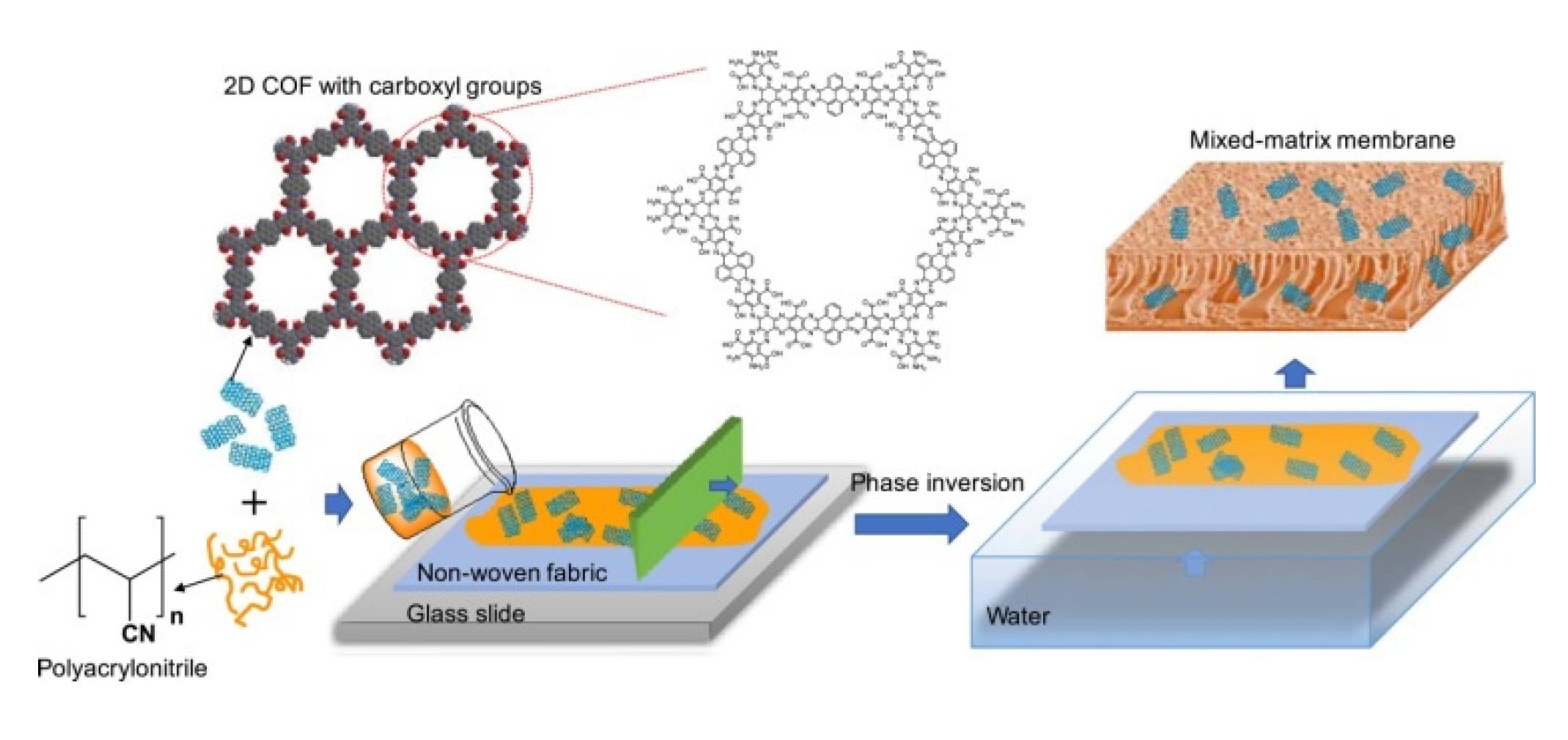
On the other hand, the asymmetric MMMs preparation method is based on phase inversion via non-solvent induced phase separation (NIPS method) using casting solutions that contain the polymer matrix and the filler (Figure 12) followed by submersing in a non-solvent bath (generally water) at room temperature to exchange the solvent and precipitate the polymer film.
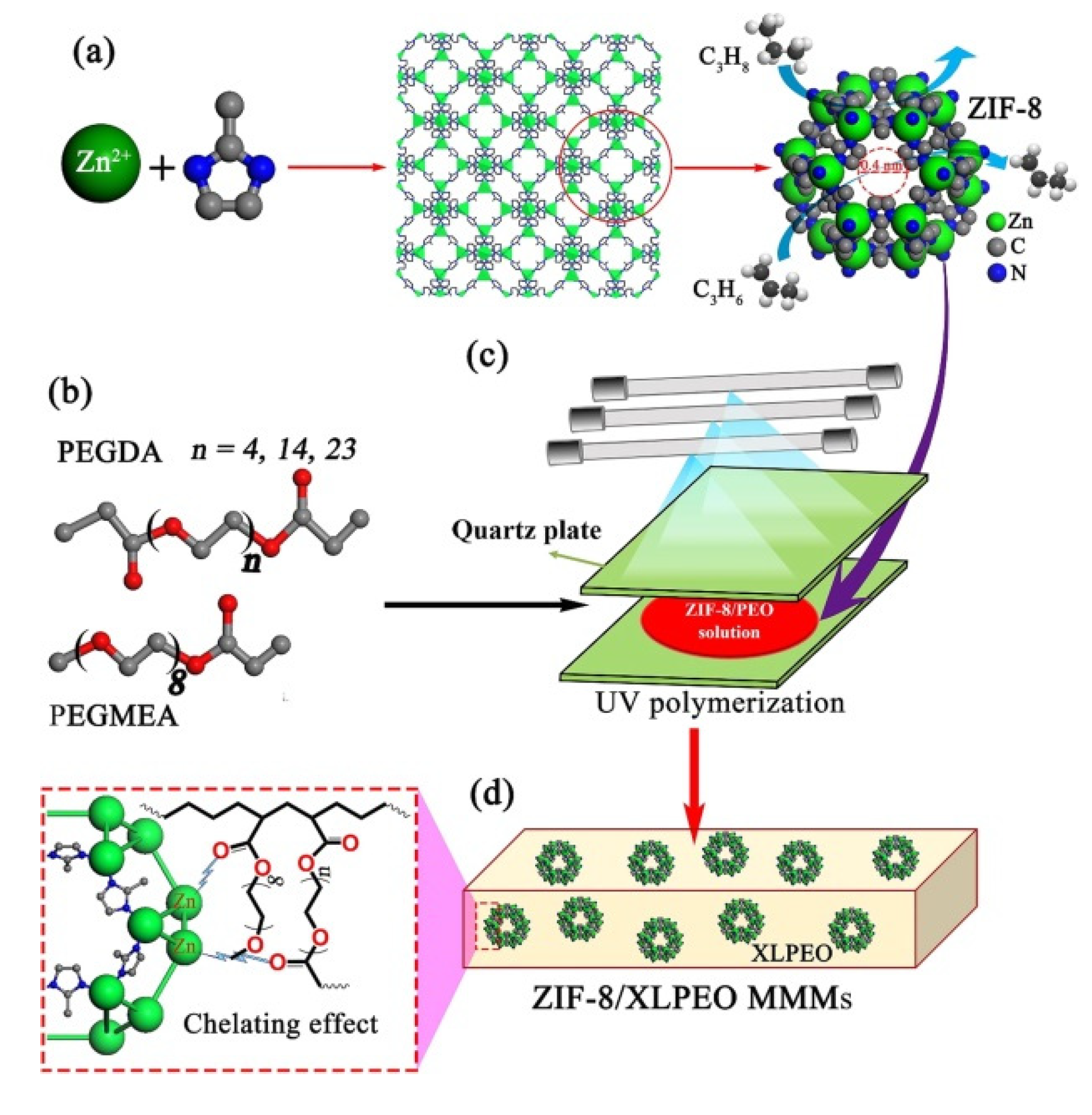
Very recently, Jiang and coworkers reported on the preparation by UV photo-polymerisation of a defect-free MMM based on MOF (Figure 13) [101].
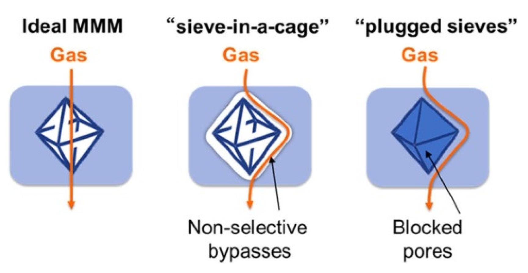
Some of the most common inorganic fillers used in the literature are based on zeolites [102,103,104], carbon molecular sieves, silica [105], metal oxide [106], carbon nanotubes [107,108,109], and graphene oxide (GO) [110,111]. Whereas polyimides (PI) [112,113,114], polysulfone (PSf) [115], polybenzimidazole (PBI) [116,117], and polyacrylonitrile (PAN) [99] have been used as a polymer matrix. An ideal MMM, must be synthesised without suboptimal structures such as “sieve-in-a-cage” or “plugged sieves” (Figure 14) [118,119].
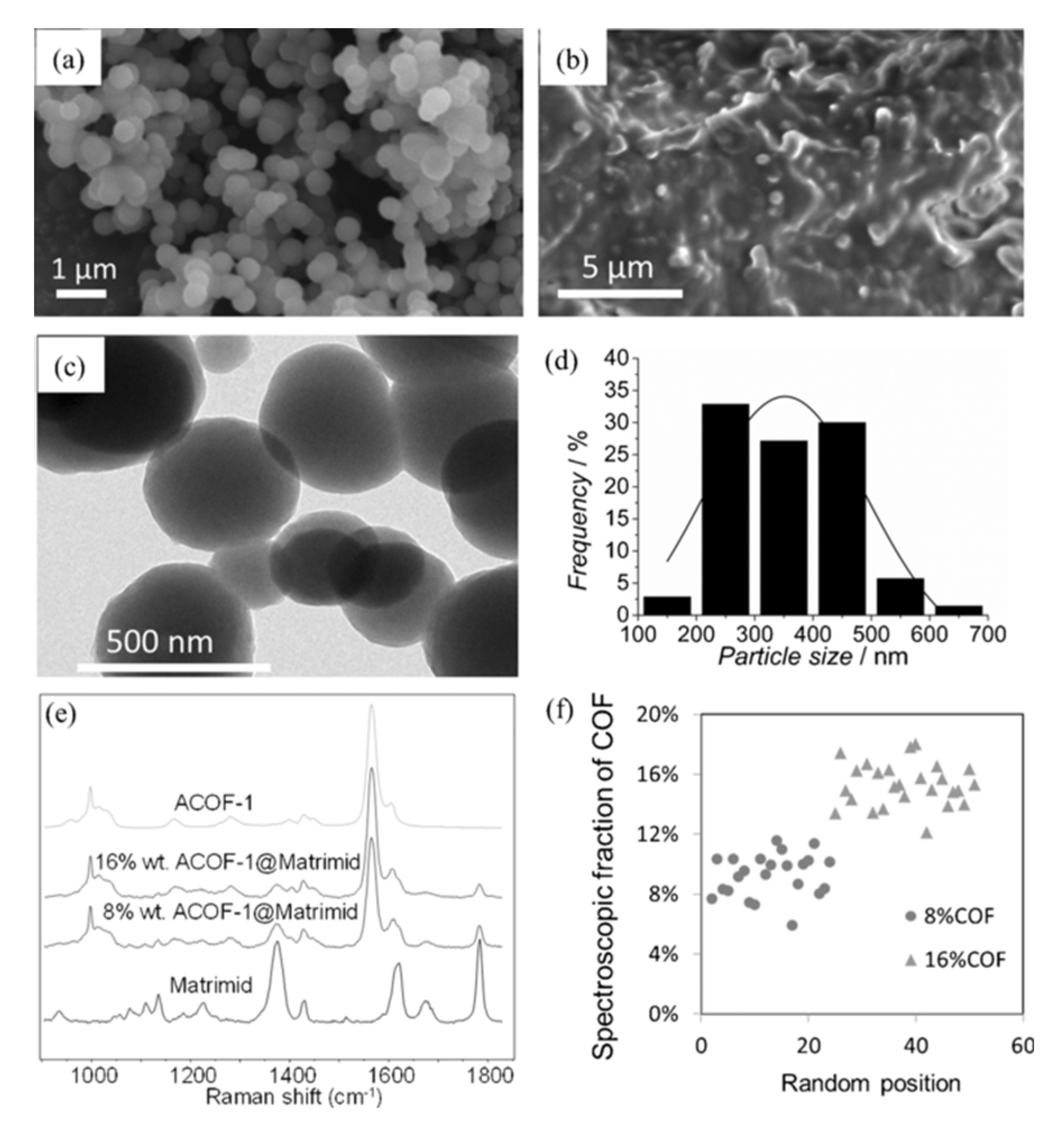
However, the poor compatibility between the polymer matrices and the inorganic fillers gives rise to non-selective interface void formation, which can affect the MMM performance. In this regard, it has been probed that the organic nature of COFs as well as the presence of organic parts in MOFs enhance the affinity of these materials with the polymers solving, in some cases, the problem of filler agglomeration and precipitation during membrane preparation process. In fact, after the first MOF-based MMM in 2004 [120] numerous types of MOF-based MMMs with diverse pore sizes and structures have been reported for different applications [34,100,121,122,123]. In the case of COFs, it was not until 2016 when Wang and coworkers reported one of the first examples of MMMs based on COFs for CO2/H2 separation. In this work, a solution of a 2D imine-based COF (COF-LZU1) in poly(vinylamine) (PVAm) was casted onto a PSf supporting membrane [124]. It is highlighted that the presence of strong covalent bonds in COFs enables the preparation of COF-based MMMs under severe conditions. Apart from the filler nature, its loading as well as the election of the correct polymeric matrix are important issues that influence the membrane performance as it was demonstrated by Shan et al. [125]. In a subsequent study, the same group was able to prepare composite membranes for proton conduction from the casting solution of polyvinylidene fluoride (PVDF) and two sulfonated COFs prepared mechanochemically (NUS-9 and NUS-10) [126]. Following a similar fabrication procedure Gascon and coworkers demonstrated the use of bulk microporous azine-linked COF (ACOF-1) for the construction of MMMs using Matrimid® as the polymer matrix. Figure 15 shows the good adhesion between the spherical COF particles and the polymer host [127].
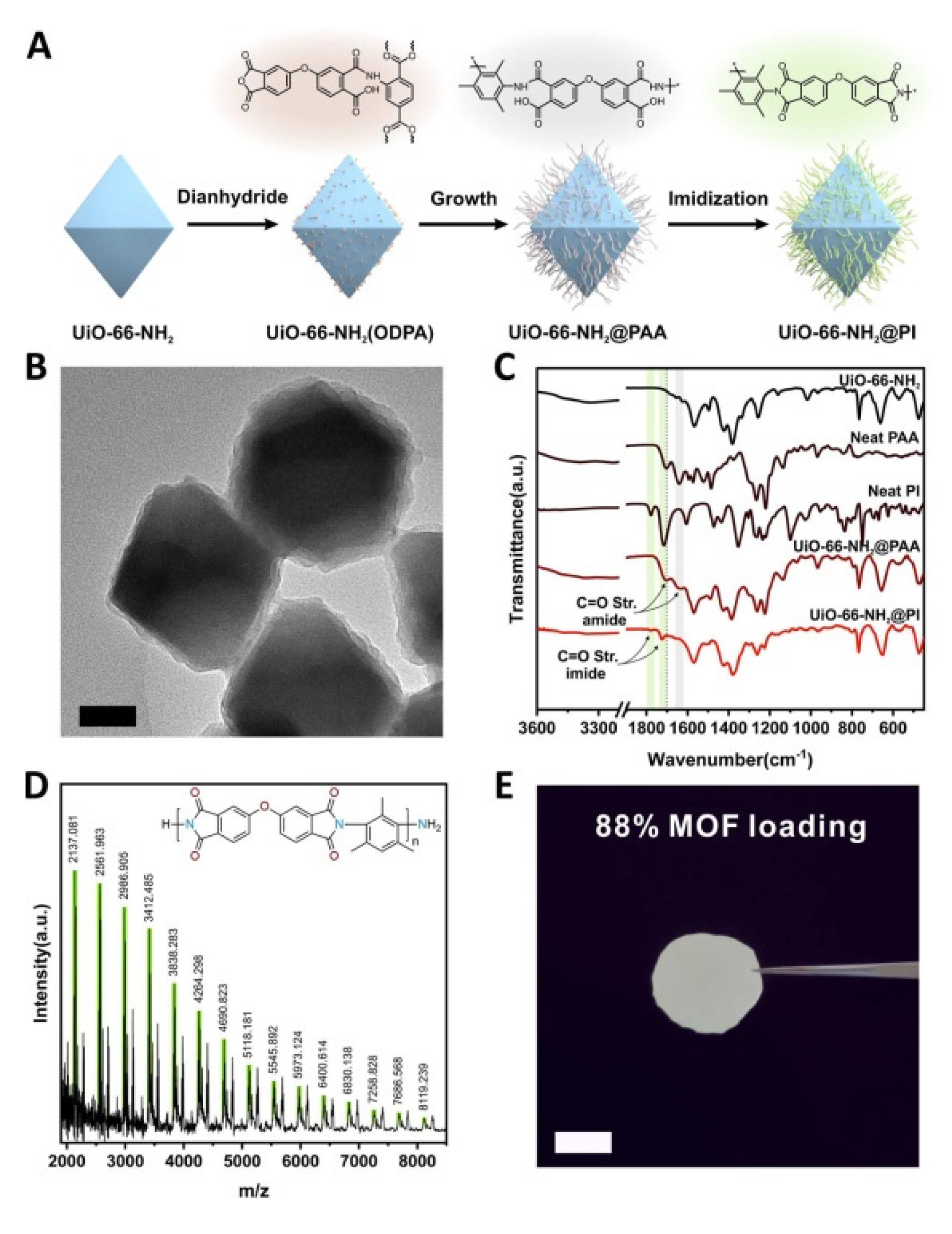
Another advantage derived from the use of this class of materials as fillers is that MOFs and COFs surface properties can be modified, either by introducing functional groups into the organic ligands or by modifying their surfaces. It is possible to create non-covalent interactions or hydrogen bonds between filler and polymer that increase the affinity with the polymer, favouring the interface compatibility [34,95,128]. Polymer functionalisation strategies have also been used to enhance MOF and COF based MMM performance [129,130]. Some of the approaches used for modifying MOF surfaces are metal or ligand exchange [131,132,133], small molecule surface modification [134,135,136,137], polydopamine modification [128], and grafting polymers onto the MOF surface [138,139]. As an example from the last approach is the strategy developed by Wang et al. based on the covalent grafting of polyimide (PI) brushes to the surface of the MOF UiO-66-NH2 (Figure 16). This strategy facilitates the preparation of polymer brush modified MMMs through the interaction (Van der Waals forces) of grafted PI brushes with the PI matrix [140].
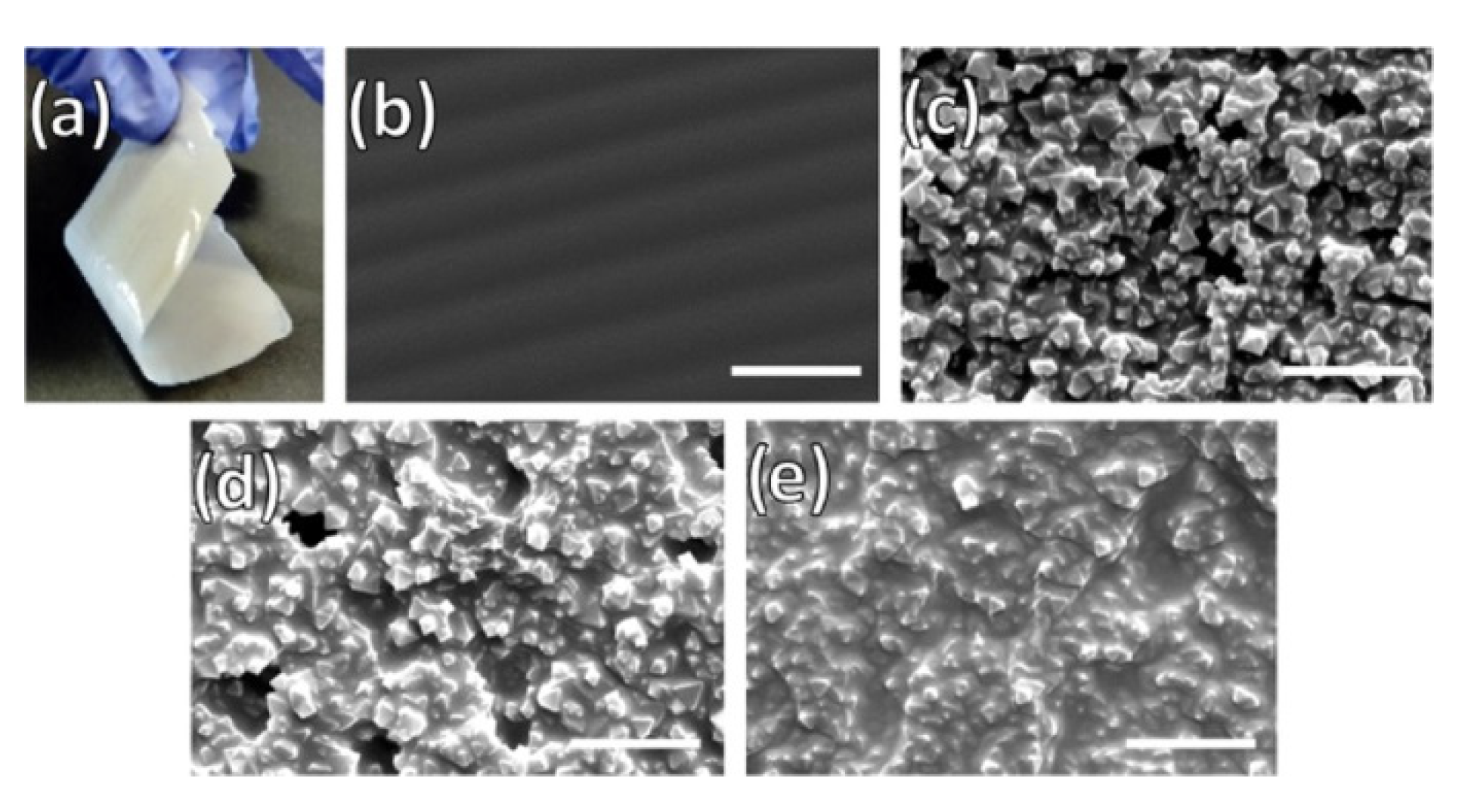
A similar approach was taken most recently by Cohen and coworkers who successfully obtained highly stable, flexible, and defect-free MMM with 50 wt % MOF loading, the highest so far achieved. This novel method consists of the covalently grafted MOF particles of UiO-66 with poly(dimethylsiloxane) (PDMS), which increased both the dispersibility and the compatibility between MOF particles and polymer matrix due to the formation of covalent bonds during the preparation of MMMs (Figure 17). This strategy was also used for the fabrication of free-standing thin-film composite membranes with a thickness less than 1 µm [118].
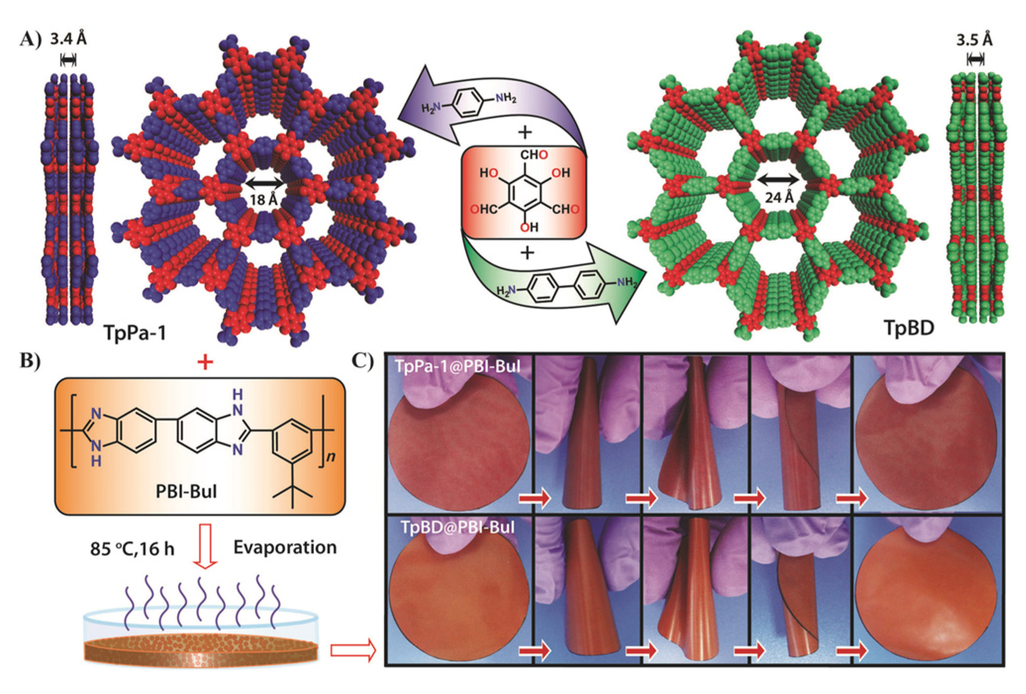
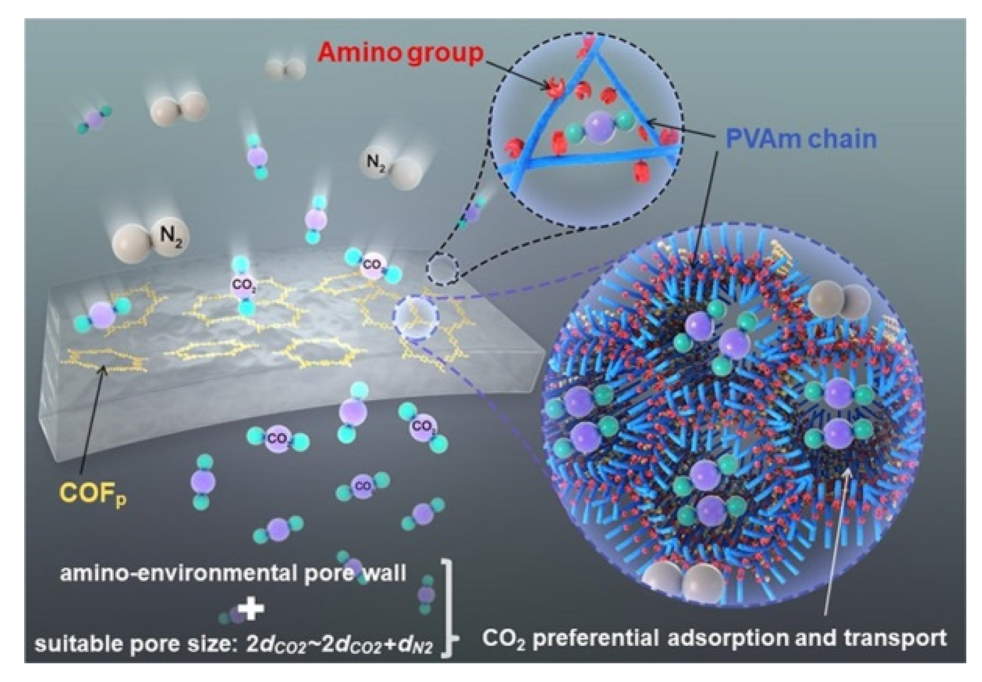
In the case of COFs, Biswal et al. showed a methodology to enhance the filler loading in the preparation of flexible and processable COF-polybenzimidazole (TpPa-1@PBI) hybrid membranes (Figure 18) via introducing intermolecular interactions between H-bonded benzimidazole groups of PBI with the COFs. With this approach, they got MMM loading up to 50% in weight [141]. Recently, Wang and coworkers have developed a new methodology based on interface regulation for increasing the compatibility of COF and the polymer matrix. Specifically, this methodology consists of the preparation of MMMs by polymer-COF hybrid materials (COFp) obtained through the immobilisation of poly(vinylamine) (PVAm) onto COFs (Figure 19). This approach enhances membrane separation performance due to the modification of the COF pore size as well as the amino environment of the pores [142].
Other decisive parameters to control before the MMM preparation are the size and the morphology of the fillers for avoiding particle aggregation and/or sedimentation [143]. Several reports on MOFs nanosheets [144,145] and nanoparticles [34,98,146,147] have shown how their incorporation into different polymers enhances the performance of MMM significantly. This enhancement is due to a better and closer integration because of the large interfacial areas at the MOF-polymer boundary. Likewise, nanoparticles can be grafted to increase the compatibility with the polymers as well as to enhance the their properties [148].
In the case of COFs, Zhao and coworkers were pioneers in using nanosheets of very stable COFs (NUS-2 and NUS-3) as fillers for the preparation of flexible MMMs. In this case, the good compatibility with the commercial polymers Ultem®, a poly(ether imide), and polybenzimidazole (PBI) used, enhanced the surface homogeneity as well as the mechanical properties of the membranes [149]. In a similar approach, 2D TpPa-1 nanosheet clusters (TpPa-1-nc) were dispersed in PEBA and spin-coated onto PVDF supports to prepare membranes used for efficient CO2 removal [150]. Liu and coworkers prepared MMMs by the blending method from COF-5 nanosheets obtained sonochemically and Pebax-1657 matrix [151].
Cheng et al. demonstrated a new strategy to increase the interfacial polymer-filler compatibility by the preparation of MOF@COF hybrid fillers. This MOF core coating with COF layers facilitated the formation of hydrogen bonding at the polymer-filler interfaces [152].
The preparation methods for MOFs and COFs membranes were well advanced during the past decade. The proper way to prepare a MOF or COF membrane is highly depending on the intrinsic properties such as structure, crystallization procedure, and compatibility of material and substrate. Additionally the demanding properties for further applications should also be considering (Table 1).

3. Properties and Characterisation of MOF and COF Membranes

The following section focuses on the characterisation techniques that allow establishing the properties of the COF and MOF membrane such as stability, flexibility, thickness, permeability, and porosity, with the aim to determine their practical application. As it was mentioned previously, the main advantage of using COF and MOF as a membrane is that their chemical/physical properties can be modified easily. This has mainly been demonstrated by chemical modification of the organic linkers [153,154]. So, membranes could be developed on demand with improved properties for specific applications.
Membranes prepared from MOF and COF material could be characterised at two levels; characterisation of MOF and COF particle/powder and the membranes prepared from the particle/powder. There are several excellent articles focusing on the characterisation of COF and MOF materials [17,155] as well as on the thin films prepared from MOFs and COFs [156,157,158]. Here we will highlight the common techniques used for characterisation of MOF and COF membranes based on fundamental properties such as structural, morphological, textural, and their transport performance.

3.1. Characterisation of Structural Properties

Since MOF and COF are crystalline porous materials, it is expected that the membranes based on these materials also show a crystalline structure. In some cases, when the structure of the used MOF and COF in bulk is well-known, the comparison of the patterns of the membrane and the bulk would confirm the membrane structure and indicate the success of the applied method.
The determination of the degree of crystallinity of the membrane is performed by X-ray diffraction (XRD) measurements, which are based on the Bragg Law [159] (Equation (1)) that establishes the relationship between the angular positions of the diffracted beams, the wavelength λ of the radiation of the incident X-rays and the interplanetary distances of the crystal planes dhkl.
λ = 2 d h k l   s i n θ
Apart from the crystallinity, XRD could provide information on the packing mode of the COF and MOF particles forming the membrane as well as the membrane orientation.
For example, Lai et al. used XRD patterns to confirm the crystallinity of TFP-DHF COF film on a support layer and also studied the stacking model of TFP-DHF COF film using XRD patterns and simulations [92]. The similar examples can be found confirming the crystallinity of the COF/MOF nanoparticles and nanosheets embedded in the matrix [160,161].
Small-angle X-ray scattering (SAXS) and wide-angle X-ray scattering (WAXS) can also be used to evaluate the crystallinity or the crystalline phase orientation of such membranes [162,163]. Additionally SAXS can measure the particle size of the nanocrystals, which could be provide useful information to improve the preparation processes [164].
Morphological properties are the most important properties to be determined for membranes since they reveal the surface roughness, continuity, thickness, and are devoid of any pinholes or surface cracks, which can originate preferential ways for the diffusion. As it was mentioned before, it is very important to grow a continuous or defect-free MOF and COF membranes [38].
To gain insight into the internal structure of the membranes, microscopy imaging techniques such as scanning electron microscopy (SEM), field emission electron microscopy (FESEM), transmission electron microscopy (TEM), and atomic force microscopy (AFM) are used. The advantage of these techniques is that it provides direct visual information on the membrane morphology. Cross-sections of COF/MOF membranes analysed under SEM, TEM, or AFM provide information on the membrane thickness and the interface between the COF/MOF layers with the matrix, for example. TEM or FESEM imaging is also used for the obtaining the pore size and shape of the COF and MOF membranes.
However, each microscopic technique has certain resolution and specific sample preparation method with TEM being the most complex. Images obtained from SEM, TEM, and AFM often show comparable results [84,92]. SEM has a resolution of up to 5 nm then, to reach a high resolution high electron-beam energy has to be applied, which can damage the samples. However, SEM could easily observe a relatively large area, which is very important for confirming the continuity of the prepared membrane. FESEM with a resolution of 0.6–0.7 nm or TEM with a resolution of 0.4–0.5 nm are more powerful tools to study the pore size of the micro-mesoporous materials. Atomic force microscopy (AFM) has higher vertical resolution, which makes it a good technique to study the surface roughness [165,166].
Ellipsometry is another interesting technique to analyse surfaces. This optical analysis technique can measure the refractive index of thin films and after the application of mathematical models calculate their thickness [167].

3.2. Characterisation of Chemical Properties

Useful techniques for the chemical characterisation of the COF/MOF membranes are Fourier-transform infrared (FTIR) spectroscopy [81,84], X-ray photoelectron spectroscopy (XPS) spectroscopy [168], energy-dispersive X-ray spectroscopy (EDX) [78,169] and Rutherford back scattering spectrometry (RBS) [89].
A FTIR spectrum shows vibration signals of chemical bonds and functions. It is an easy method to confirm the formation of COF/MOF selective layers and study the membrane surface modifications. In some cases, FTIR has been used to study the interface connections between the COF/MOF and matrix due to the presence of specific chemical bonds [87].
XPS measures the binding energy of atoms, which could distinguish the oxidation degrees of elements. XPS can be used for chemical composition analysis and sometimes can be completed and compared with the FTIR analysis [84,92,170]. It is mainly used to analysis the chemistry of the surface providing the elemental composition of the membrane surface.
EDX spectroscopy is usually coupled with SEM or TEM imaging. A quantitative map of elements could be constructed based on the nature and intensity of the interacted X-ray with different atoms and elements present within the detecting region (observation window). The elemental composition could directly be mapped on the SEM or TEM images. EDX is a very useful tool to detect the metal elements of MOF membranes and also different elements present in COF membranes [78,171].
RBS can probe materials by the scattering of an ion beam, which provides the atomic composition and structure information via using modelling software. The elements composition can be determined from the positions of peaks in the energy spectrum. Structure information such as thickness can be determined from the shift position of the peaks [88,89]. It is especially useful for the analysis of a multilayer membrane compare to XPS and EDX, which permit the elemental study on the surface of membrane.
For specific membrane applications the membrane chemical stability is a very important issue to consider. Chemical stability tests are intended to simulate the real operative conditions to which COF and MOF membranes are going to be subjected. For this, the membranes are exposed to different solvents (water and organic solvents) under different conditions (temperature, time, pH, etc.). Indeed, in some cases, it is necessary to carry out a post-synthetic treatment on the membrane with the aim to improve its stability and performance. For example, the membranes can be coated with amphiphilic surfactants after its activation in order to protect them from ambient moisture [172].

3.3. Characterisation of Thermal and Mechanical Properties

Other important issues to take into account are the thermal and mechanical stability of the MOF and COF membranes. The thermal stability and flexibility of the membrane can be studied by thermogravimetric analysis (TGA) and differential scanning calorimetry (DSC). TGA is based on measuring the amount and rate of the sample mass changing as a function of temperature or time under a controlled atmosphere. This technique is especially useful for establishing the maximum temperature that the membrane can reach before decomposition. On the other hand, DSC is used to study the difference in the amount of heat required to increase the temperature of a sample and reference as a function of temperature. Thermal transitions of membrane as well as the temperature at which the transition occurs (glass transition temperature, Tg) could be determined via this technique [173].
The evaluation of the mechanical resistance of the MOF and COF membranes would allow studying the effect of the applied pressure and the mechanical stress on the membrane structure [174]. The common parameters to study are tensile strength, elongation at break, and Young’s modulus.

3.4. Textural Characterisation of the Membrane Surface

The Brunauer–Emmett–Teller (BET) surface area was calculated from N2 adsorption isotherms measured at 77 K. The experimental data derived from these measurements allowed the determination of the pore size distribution by the application of different models as a function of the pore geometry. The isotherm shape also gives some information about the pore size [87,162,163].
The positron annihilation lifetime spectroscopy (PSA) could also be a powerful technique to characterise the free volume of the membrane. However, it has not been broadly used in the studies of MOF and COF membranes. This technique is based on the principle that the positron annihilation rates through interactions with electrons from different materials are different. The lifetime of positron can be obtained by the emission time of positrons from a radioactive source (for example: 22Na, 13 μCi) and detection of the gamma rays released from the positron annihilation. When positrons are injected into a material containing free electrons (such as metals or semiconductors), the implanted positrons will annihilate with the electrons present in the material. For insulators materials such as polymers, MOFs, and COFs implanted positrons interact with electrons in the material to form positronium (Ps), which is a hydrogen-like bound state of an electron and a positron. In case of porous materials, positrons and positronium tend to penetrate and localise in vacancies/voids in the materials and annihilate less rapidly than in the bulk material. For example, in metal simple coulomb attraction forces positrons into electron-decorated vacancies, whereas in insulators the reduced dielectric interaction in a void energetically favours trapping neutral positronium in low-density regions [175]. Ps can exist in two spin states: Para-positronium(p-Ps) that is at a singlet state and Ortho-positronium(o-Ps) that is a triplet state. In molecular materials, o-Ps is easily trapped in the potential well of free volume cavities. So, the lifetime of o-Ps can be converted to the free volume of the material by following Equations (2) and (3):
τ = 1 2 [ 1 r r + Δ r + ( 1 2 π ) s i n ( 2 π r r + Δ r ) ] 1
v = 4 π 3 r 3 I
where τ, r, ∆r, and I are the o-Ps pickoff lifetime, the radius of the free volume cavities, the thickness of the electron layer, and the intensity of o-Ps [175,176].
Wang et al. applied PSA to determine the free volume of sodium alginate-polyacrylonitrile (SA-PAN) hybrid membrane by incorporation of COF SNW-1 on the surface [177]. Similar examples can be found for obtaining the pore size and distribution for MOF membranes [178,179].
Quartz crystal microbalance (QCM) measures mass changes by measuring the change in frequency of a quartz crystal resonator. QCM can be used under vacuum, in the gas phase and in the liquid phase. For COF and MOF characterisation, QCM can give information on their thickness, porosity and viscoelastic properties of the membrane in liquid media by comparing sorption behaviours of different guest molecules. QCM is a highly effective tool at determining the affinity of molecules uptake to functionalised COF and MOF membrane, which can help the study of transport mechanism of the membrane towards different guest molecules [180,181].
The adsorption/desorption of organic solvent on membranes can change the surface optical characteristics, which could be measured using ellipsometry. This technique coupling ellipsometry and sorption of solvent is called ellipsometric porosimetry, which could provide information on thickness, pore size, and pore size distribution of the COF/MOF layer. However, so far it has not been used for the characterisation of the COF/MOF membrane [182].

3.5. Membrane Functional Characterisation

Depending on the final MOF and COF membrane application it will be necessary to carry out additional studies that would predict how they would function under real operative conditions. The following section describes the main parameters determining the potential of MOF and COF membranes for gas and liquid separation as well as for fuel cells. One of the most important factors of membrane performance used in separation processes is the transport capacity, which can usually characterised by two parameters: flux (or permeance) and rejection (or selectivity) [183]. Flux measured from the membrane process is defined as the volume flowing through the membrane per unit area and per unit time, and is usually expressed in terms of L m−2h−1, while permeance is normalised to the applied pressure, and therefore expressed in terms of L m−2h−1bar−1. Rejection of all the substances could be calculated as a function of the solute concentration in the permeate, Ci,l, and the solute concentration in the retenate (or feed) side, Ci,0 Equation (4):
R e j i ( % ) = 100 ( 1 C i , l C i , 0 )

3.5.1. Gas Permeation Capacity

Both defined pore size and functional groups present in the MOF and COF structure make them good candidates for gas separation. In terms of gas permeation and rejection through MOF and COF based membrane, single gases (H2, CH4, N2, and CO2) permeability can be obtained by various gas sorption isotherms and then calculated from the rate of pressure increasing (dp/dt) at a steady state according to Equation (5) [149]:
P = 273 × 10 10 760 V L A T ( p 2 × 76 14.7 ) ( d p d t )
where P is the membrane gas permeability in Barrer (1 Barrer = 1 × 10⁻¹⁰ cm3 (STP) cm cm−2 s−1 cm Hg−1 or 3.348 × 10⁻¹⁶ mol mm−2 s−1 Pa−1), V represents the volume of the downstream reservoir (cm3), L refers to the membrane thickness (cm), A is the effective membrane area (cm2), T is the operating temperature (K), and p2 indicates the upstream pressure (psia) [149].
The ideal gas selectivity of component i over component j is calculated on the basis of their different permeability as Equation (6) [149].
α ( i j ) = P i P j
In a similar way the mixed gas permeability is calculated from Equation (7) [149]:
P = 273 × 10 10 760 y i V L A T ( x i p 2 × 76 14.7 ) ( d p d t )
where the xi and yi represent the molar fractions of component i in both up- and down-stream.
The mixed gas separation factor is calculated on the basis of Equation (8) [149]:
S ( i j ) = y i / y j x i / x j
The permeability or selectivity for the same gas pair based on single gas and mixed gas are usually different owing to the competitive adsorption and diffusion of the mixed gas in the membrane [149]. The selectivity defined in membrane-based separation emphasises the difference of gas permeability, which is how fast the gas can penetrate through the membranes. In membrane based gas separation can be typically described using the solution−diffusion model, in which permeability P can be expressed by Equation (9):
P = S × D
where S is the solubility of a particular gas in polymer and D is the diffusivity of that specific gas [149]. The gas solubility is controlled by the affinity of gas toward polymer membrane surface and diffusivity depends on the relative size of the gas molecular to the pore size of the framework. In case of MOF and COF mixed matrix membranes, adding fillers (MOF or COF) into polymers can affect both S and D, while the affected trend depends on the filler’s properties, loading and other factors as well.
To compare the membrane performance with the existing materials, there is a well-known trade-off relationship between permeability and selectivity, as originally reported Robeson in 1991 (revised in 2008) [184,185].

3.5.2. Liquid Permeation and Rejection Capacity

Liquid transport capacity of the membrane is a very important factor for several applications. In an aqueous media process, hydrophilic membranes can facilitate the water transport, increase the process efficiency and reduce the cost. Similarly, for non-aqueous solvents a hydrophobic membrane is required. Usually, the permeation properties for a liquid are determined by passing protic and aprotic organic solvents (acetonitrile, water, ethanol, and methanol) through the membrane under specific conditions such as concentration, temperature, thickness, pressure, and/or electric field. The membrane surface hydrophilicity is usually tested by contact angle measurements. The contact angle of a liquid drop on an ideal solid surface refers to the mechanical equilibrium of the drop under the action of three interfacial tensions Equation (10), as was described by Thomas Young in 1805 [186].
γlvcosθY = γsvγsl
where γlv, γsv, and γsl represent the liquid–vapour, solid–vapour, and solid–liquid interfacial tensions, and θY is the Young’s contact angle or static contact angle. By Young’s equation, small contact angles (≤90°) correspond to high wettability, which means the membrane surface is hydrophilic. In the contrast, while large contact angles (≥90°) correspond to low wettability, which means the membrane surface is hydrophobic. However, in practice, there exist many metastable states of a droplet on a solid, and the observed contact angles are usually not equal to θY. If the three-phase contact line is in actual motion, the contact angle produced is called a “dynamic” contact angle. At a low measuring speed, dynamic contact angle could be close or equal to a properly measured static contact angle [187]. Solvent transport capacity can also be directly measured by a dead-end filtration system [92]. The transport capacity defined with solvent flux (J) and permeance (P) are calculated by Equations (11) and (12):
J = V/At
P = J/∆p
where V is the collected solvent volume (L) across the membrane during a time period of t (h), A is the effective membrane area (m2), and Δp is the trans-membrane pressure drop (bar) [92].
In case of liquid separation, especially dehydration of the water–alcohol mixture through pervaporation is well studied in polymer-MOF or COF mixed matrix membranes [84,168]. The permeation flux (J, g m−2h−1), separation factor (α), and pervaporation separation index (PSI) are calculated from Equations (13)–(15):
J = Q/At
α = P W F W P A F A
PSI = J (α − 1)
where Q (g) is the weight of permeate through the membrane area A (m2) under the time interval t (h) for permeate collection, and P and F are mass fractions of water (W) or alcohol (A) in the permeate and feed solution, respectively [84]. Incorporation of MOFs and COFs with hydrophilicity groups can enhance the hydrophilicity of the membrane, which increases the water flux during the membrane process. In addition, ordered pore size, good compatibility, and multi-functionality of MOFs and COFs can also improve both the membrane permeability and the selectivity facing different liquid mixture.

3.5.3. Solute Permeation and Rejection Capacity

There are two main types of solute usually studied in membrane applications: salts and organic compounds. The alts’ rejection depends on pore size, membrane surface charge, and the ions present in the solute. Larger pore size leads to higher permeation and lower selectivity towards different ions. However, ions with the same charge as the applied membrane and multivalent ions show stronger repulsion through the membrane. By these principles, membranes with the same charge as the targeting ions have a relatively high rejection and good antifouling properties. For example, Wu et al. have prepared a thin-film nanocomposite (TFN) membrane incorporating COF (SNW-1) into the polyamide (PA) layer on a polyether sulfone (PES) substrate (PA-SNW-1/PES). Due to the PA layer that is negatively charged the TFN membrane shows a stronger repulsion towards di-anionic anions (SO42−) than monovalent anions (Cl) [87]. The concentration of the salt solution was used to detect the conductivity of the solution using an electrical conductivity meter. The salt rejection was then calculated using Equation (4).
As for organic compounds, dyes are usually used as the model compound to study the rejection properties of MOF and COF membrane towards organic compounds. There are various different types of dyes with different solubility (water soluble or solvent soluble) and functional groups that would be used for this purpose. Dye rejection depends mostly on the membrane pore size. The dye rejection measurements are conducted in water or in organic solvents and the concentration of dyes are usually measured by UV-vis spectroscopy and the rejection is calculated using Equation (4) [92,188].

3.5.4. Proton Conductivity Properties

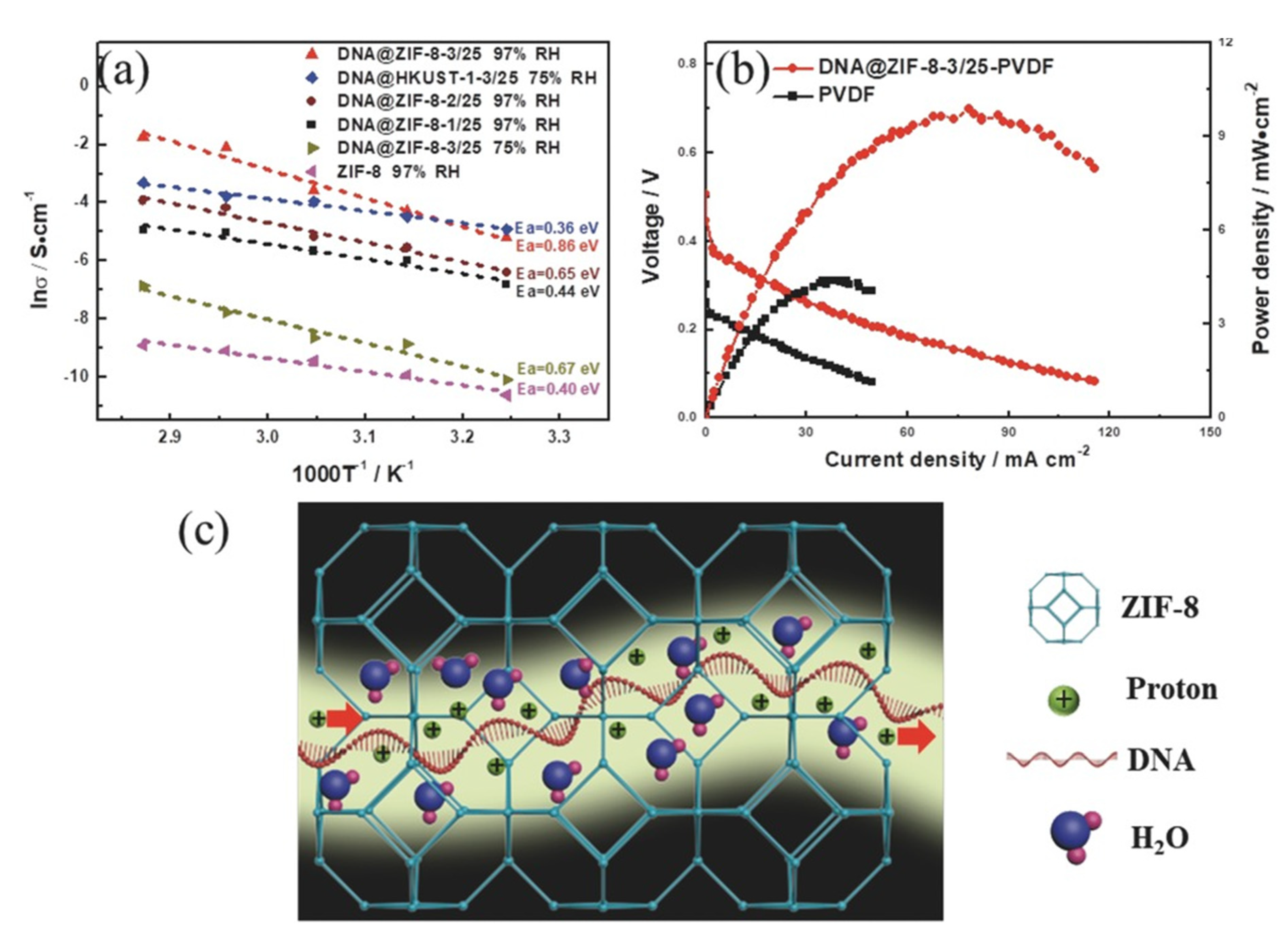
COF and MOF membranes have also been used as a solid electrolyte in fuel cells. Such membranes must have good proton conductivity. For this purpose, ionic conductivity measurements are performed on MOF/COF pellets using electrochemical impedance spectroscopy [126,189,190,191,192]. Conductivity values are calculated from equation σ = L/(R × A), where σ is the conductivity value (S cm−1), L the thickness of the sample (cm), A is the electrode area (cm2), and R (Ω) is the electrolyte resistance corresponding to the real Z′ Nyquist plot. In some cases, the conductivity values measured at different temperatures are correlated by means of an Arrhenius type equation that allows obtaining the activation energy (Ea) of the system, which will establish the type of mechanism that dominates the conduction either by Grotthuss (≤0.4 eV) or Vehicular (>0.4 eV) [193]. The proton conductivity and activation energy could be improved by optimising the interfacial interactions [189,190], introducing functions that provide additional proton-transport sites [191].

4. Applications of MOF and COF Membranes

Membranes are widely used in processes engineering since they are often technically simpler and more energy efficient than conventional separation techniques. Particularly, they are used on a large scale to produce potable water from sea and brackish water, to clean industrial effluents and recover valuable constituents, to concentrate, purify, or fractionate macromolecular mixtures in the food and drug industries, and to separate gases and vapours in petrochemical processes [165]. Among all the varieties of membranes that exist in the market, the ability of MOFs and COFs to easily control their pore size and shape as well as their properties, makes them ideal candidates for different membrane applications [29,35,38,194,195]. Here, we will focus on some of the most recent progress made in MOF and COF membranes for gas separation, liquid separation, and fuel cells.

4.1. Gas Separation

Since the discovery of MOFs and COFs, one of their main applications was related to the capture and separation of gases of industrial and environmental interest. Later on, their processing in the form of membranes, to be tested under real operating conditions, also gave rise to very interesting results in CO2 recovery, H2 purification, and hydrocarbon separation among others, as it has been already discussed in previous reviews [31,196,197,198,199,200,201,202]. Zeolitic imidazolate frameworks (ZIFs) are often used in the preparation of membranes for gas separation owing to their high thermal and chemical stability [114]. However, the separation of small gas molecules by the use of continuous COF membranes is quite challenging due to the characteristic pore size of these materials.

4.1.1. CO2 Recovery

Carbon dioxide is one of the main gases emitted by thermal power plants along with N2, O2, H2O, and its separation before its release into the atmosphere, especially from N2, is very important since it is implicated in the greenhouse effect. Likewise, CO2 separation from CH4 in natural gas purification is also very important for avoiding pipeline corrosion among other issues. Usually, polymeric membranes offer an impact solution to these separations, replacing other solutions like distillation, which is highly energy consuming. However, CO2 can produce polymer plasticisation; it is changes of the polymeric structure that makes the membrane unusable. It is important to highlight that due to the volume of the gas mixture to treat in CO2/N2 and CO2/CH4 separations, permeability in membranes is preferred than selectivity as well as strong interactions with CO2 molecules. To meet the last requirement, the rational design of MOF and COF structures allows incorporating functional groups with high affinity to CO2 such as, –NH2, –OH, and –COOH that will improve the CO2 adsorption properties. Taking this strategy into account, Lin and coworkers demonstrated the beneficial effect caused by the post-synthetic modification with 3-isocyanatopropyltriethoxysilane of the CAU-1 MOF membrane decorated with amino groups, which gave rise to relatively high permeabilities as well as increasing the CO2/CH4 selectivity values [203].
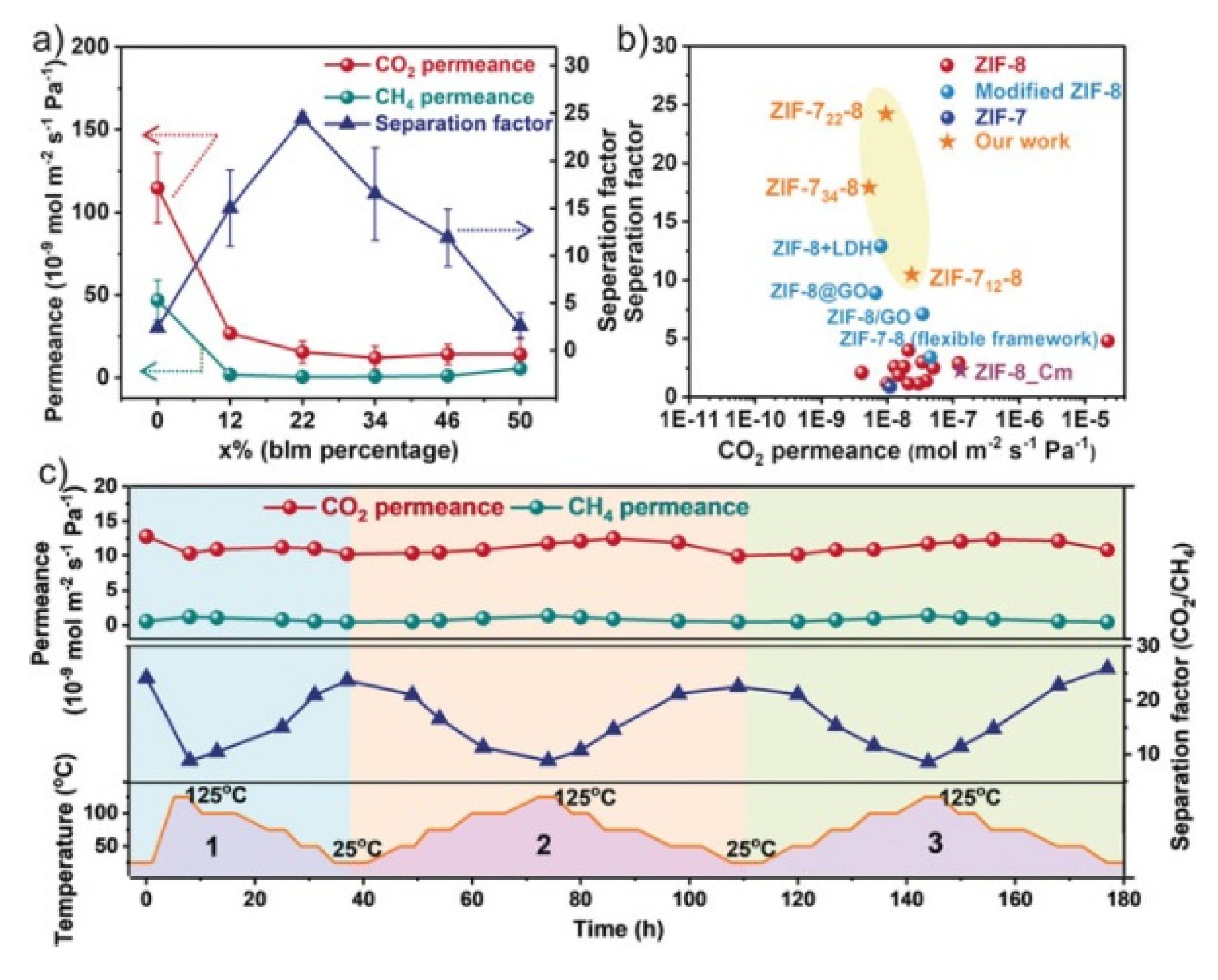
The separation of CO2 through the use of MOF membranes has been widely reported in many reviews [34,204,205,206,207]. Usually, the pore size of these structures plays an important role as molecular sieves. For example, one of the most interesting ZIFs to carry out the CO2/CH4 and CO2/N2 separations by molecular sieving is ZIF-8 since its pore aperture is 0.34 nm and shows high thermal and chemical stability. However, its flexible lattice originates the low separation factors. Wang and coworkers reported an excellent mixed linker strategy for the preparation of ZIF-7x-8 membrane (440–600 nm) with high separation efficiencies due to the decrease in pore size. Particularly, the maximum separation factors obtained for CO2/CH4, H2/CH4, and CO2/N2 were 25, 17, and 20, respectively, higher than other ZIF-8 membranes reported. Moreover, the performance is maintained after 180 h (Figure 20) [205].
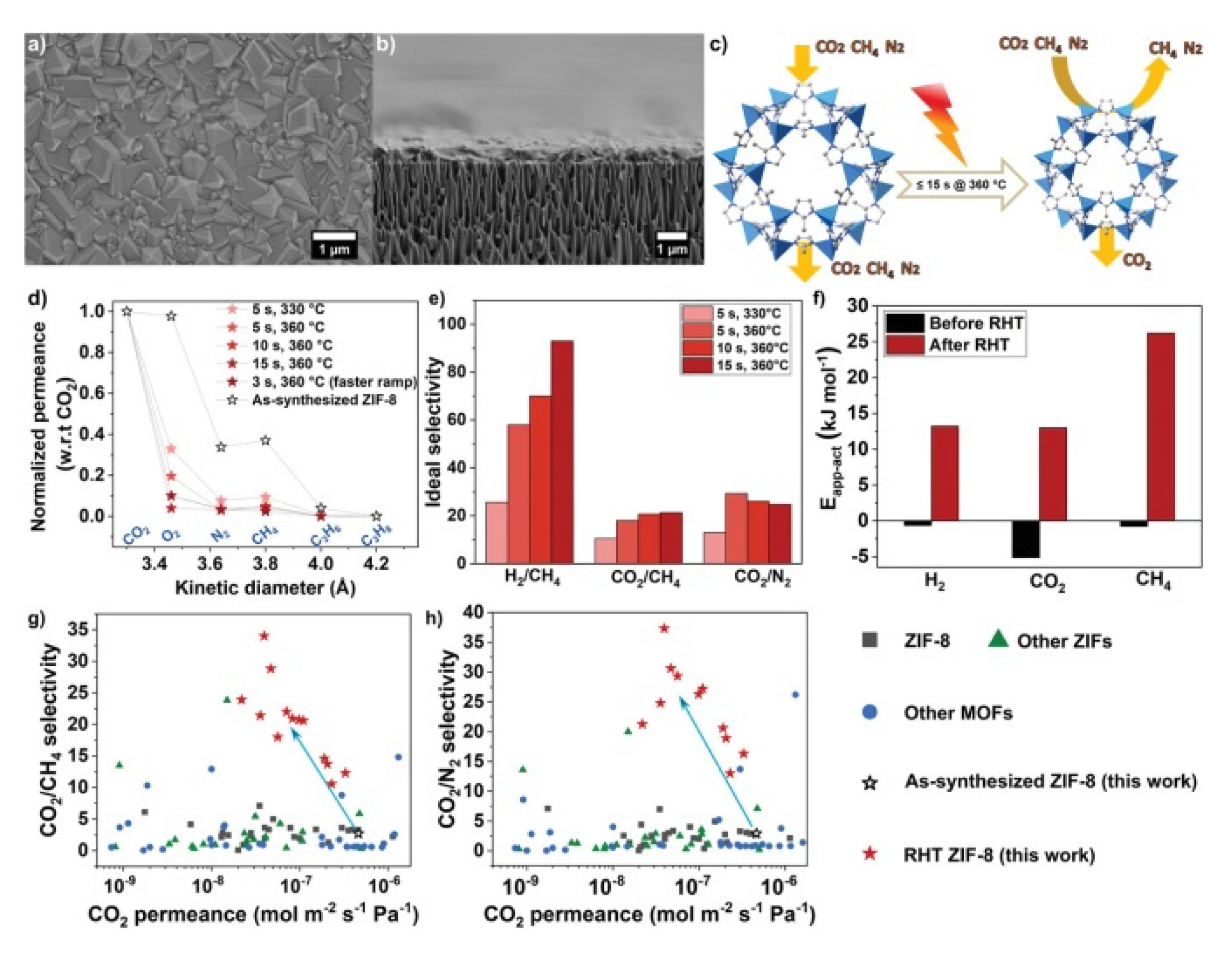
Very recently, Babu et al. reported another approach to limit the lattice flexibility in ZIF-8 by carrying out a post synthetic rapid heat treatment (RHT) on the ZIF-8 membrane, which lead to an increase of the lattice stiffness as well as the highest CO2/CH4 and CO2/N2 selectivity reported so far (Figure 21) [208]. This MOF was also used by Caro and coworkers for the preparation of a ZIF-8-ZnAl-NO3 layered double hydroxide (LDH) composite membrane on the γ-Al2O3 support that showed and the CO2 permeance is 0.0977 × 10⁻⁷ mol m−2s−1Pa−1 and the separation factor for CO2/CH4 of 12.9 that exceeded the corresponding Knudsen values (0.6) due to the affinity of LDH for CO2 [209]. ZIF-7 that presents a pore size about 0.3 nm has also been used for this application. For example, Coronas and coworkers fabricated by microfluidic a ZIF-7 membrane on the inner face of a polysulfone (PSF) hollow fibre with the highest separation factors of CO2/N2 and CO2/CH4 obtained for this ZIF [210].
Caro et al. have developed a 2D COF membrane based on ACOF-1 and alumina by solvothermal synthesis. ACOF-1 on the surface of alumina support provides a pore size of about 0.94 nm and abundant polar groups on the pore wall, which are good to enhance the CO2 capacity and CO2/CH4 selectivity. The experiment results show the membrane provided a high selectivity for the CO2/CH4 gas pair with a reasonable CO2 permeance. The overall performance surpasses the Robeson upper bound (2008) shows better performance than existing materials [211].
Apart from the recent reports based on continuous ZIF membranes, the majority of MOF and COF membranes are based on MMM since they combine the properties of crystalline porous materials and polymers. However, as it was mentioned in Section 2.4, a high compatibility and dispersity between both materials is needed to get gas separation performances and avoid membrane defects like pinholes or cracks. The filler properties such as morphology, size, orientation as well as the type of polymer matrix used will have important consequences on the permeability and selectivity values. Zheng et al. studied the influence of ZIF-8 particles size (40, 60, 90, and 110 nm) obtained by the microemulsion method at different loadings (from 0 to 20 wt %) in the preparation of Pebax based MMMs. They found that the CO2 permeability increased with the filler loading as well as for the particle size owing to the increase in free volume and surface area. The best results were obtained for the MMM loads with 5 wt % of ZIF-8 and a particle size of 90 nm, which showed a CO2 permeability of 99.7 Barrer and CO2/N2 selectivity of 59.6 [212]. In another approach, Lai et al. applied thermal annealing treatment to ZIF-8 particles in order to modify their structure by introducing little defects before their integration into a poly(styrene-co-butadiene) (SBC) polymer matrix. The results showed an increase of the CO2 permeability and CO2/N2 selectivity in comparison with the naked SBC membrane due to the removal of host molecules and the breaking off the Zn‒N bond in the annealed ZIF-8 framework at 300 °C [213]. Very recently, Mandal and coworkers studied the CO2/N2 separation performance of ZIF-8 nanoparticles (100 nm) dispersed into a poly(vinyl alcohol) (PVA)/piperazine glycinate (PG) polymeric matrix and showed that for 5 wt % ZIF-8 loadings the CO2 permeance (82 GPU) and CO2/N2 selectivity (370) of the resulting MMM increased 82.2% and 76.2%, respectively, compared to the bare PVA/PGG membrane. These results exceeded the Robeson’s upper bound [214]. Yang and coworkers reported ZIF-8/P84 MMMs with a CO2 permeability of 10.92 Barrers with CO2/CH4 separation factor of 92.6, assuming an improvement of 339% and 35.7% with respect to the pure polymer. These values also surpass the Robeson’s upper bound [215]. Bae and coworkers studied the CO2/CH4 separation performance of a MMM that integrated 2D (ns-CuBDC) and 3D (ZIF-8) MOFs as a filler. The combination of both MOFs gave rise to an improvement in the CO2/CH4 selectivity as well as CO2 permeability [216]. The use of a heterogeneous mixture of two different polymer matrixes for the preparation of MMM has also been very recently reported by Coronas and coworkers. They demonstrated the positive effect on the CO2/CH4 and CO2/N2 separation performance by the incorporation of 10 wt % ZIF-8 nanoparticles in a heterogeneous blend of the highly permeable polymers 6FDA-DAM and PIM-1 (polymer of intrinsic microporosity, PIM) [217]. The preparation of MMMs based on PIM-1 to improve both its selectivity and its permeability has been widely studied also by other authors. For example, Khdhayyer et al. studied PIM-1 based MMMs prepared from the incorporation of different types of MIL-101 MOF: MIL-101 (particle size ca. 0.2 µm), NanoMIL-101 (particle size ca. 50 nm), ED- MIL-101 (MIL-101 functionalized with ethylene diamine), and NH2-MIL-101 (MIL-101 synthesised using 2-aminoterephthalic acid). The best results were obtained for MIL-101, which, maintaining the excellent ideal CO2/N2 and CO2/CH4 selectivity of the bare polymer enhanced the CO2 permeability reaching a value of 35.600 Barrer for 47 vol. % MIL-101. Apart from the PIM-1/MIL-101, PIM-1/nanoMIL-101 also surpass the separation trade-off defined by Robeson [218].
The excellent stability of zirconium MOFs as well as their suitable pore size (MOF-801 [219], Bipyridine-based UiO-67 [220], UiO-66-NH2 on@GO [221]) makes them ideal candidates for the preparation of MMM based on different polymer matrixes always leading to improvements in gas separation performances in comparison to the bare polymer. In this context, very recently, Yu et al. reported an excellent methodology to build a CO2 free-ways MMMs based on different loadings of UiO-66-CN linked covalently to PIM-1 and subjected to a heat treatment. The resulting UiO-66-CN@sPIM-1 MMM showed exceptionally high CO2 permeability values (15,433.4 and 22,665 Barrer), which surpass the upper-bound of Robeson as well as long-term stability (Figure 22) [222].
Aiming to improve the filler–polymer compatibility, Cohen and coworkers grafted post-synthetically hydride-terminated poly(dimethylsiloxane) (PDMS; <5 wt %) to UiO-66 particles, which gave rise to free-standing and defect-free 50 wt % MOF-loaded MMMs with CO2 permeabilities higher than PDMS membranes [118]. In similar work, Huang and coworkers grafted imidazole-2-carbaldehyde (ICA) to UiO-66-NH2 before its incorporation to the Matrimid polymer matrix. In this case, the presence of ICA apart from a decrease in the pore size of the MOF improved 40% the CO2/CH4 selectivity of UiO-66-NH2@ICA/Matrimid® with respect to UiO-66-NH2/Matrimid® MMM [223]. Chen et al. reported an innovative approach consisting of the preparation of MOF@COF hybrid materials (UiO-66-NH2 cores covert by TpPa-1 layers) to be used as fillers in the preparation of MMMs. The good polymer-filler compatibility as well as the size-selective pores in MOFs gave rise to improvements of 48% and 79% in both CO2 permeability and CO2/CH4 selectivity, respectively [152].
Selection of the MOF and the polymer matrix has important influence in the gas separation performance. Taking this into account, Sabetghadam et al. prepared eight MMMs with four different MOFs at 25 wt % loadings (NH2-MIL-53(Al), MIL-69(Al), MIL-96(Al), and ZIF-94) and two different polymer matrixes (6FDA-DAM and Pebax) that were tested for CO2/N2 separation. All MMMs exceeded the Robeson upper-bound limit due to an enhancement in CO2 solubility that caused improvements in both the selectivity and the permeability of this gas, obtaining the best results for MIL-96(Al) [224].
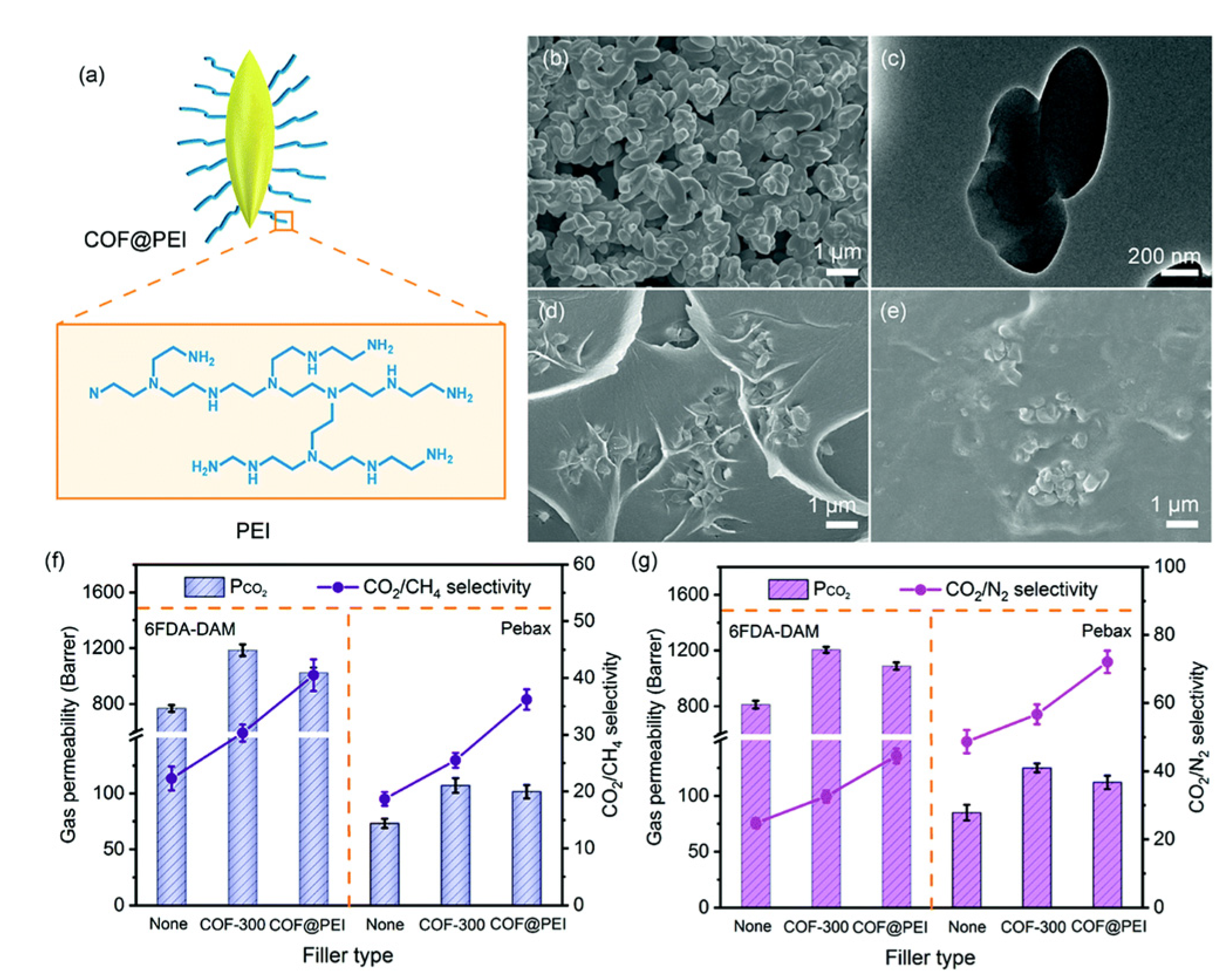
In the case of COF MMM, Kang et al. dispersed two water stable 2D COFs (NUS-2 and NUS-3) into poly(ether imide) (Ultem®) and polybenzimidazole (PBI) polymer matrixes. In the case of NUS-2@Ultem and NUS-3@Ultem reached selectivity for CO2/CH4 of 33 and 30, respectively with low CO2 permeability (10 and 15 Barrer, respectively) [149]. Karhul and coworkers incorporated chemically stable isoreticular COFs (TpPa-1 and TpBD) to the polymer (PBI-BuI) matrix. The resulting MMMs exhibited H2, N2, CO2, and CH4 permeability values up to 7 times higher than for the bare polymer while maintaining CO2/N2 and CO2/CH4 separation factors [141]. Gascon and coworkers evaluated the beneficial effect of the presence of azine-linked COF (ACOF-1) in the polymer matrix Matrimid (ACOF-1@Matrimid) for the separation of CO2 from equimolar mixtures of CO2/CH4. Particularly, at 16 wt % ACOF-1 loading the CO2 permeability were more than double the original Matrimid® polymer and the CO2/CH4 separation factors considerably higher due to both fast transport of gases and CO2-philic properties of the filler [127]. The same group demonstrated the importance in the election of the filler–polymeric matrix pair by the preparation of MMMs for CO2/N2 separation with three different polymers and the ACOF-1 COF at different loadings. The best result was obtained for the MMM based on Matrimid® and 16 wt % ACOF-1 loading, which showed a selectivity increase from 29 to 35, as well as an enhancement in permeability from 9.5 to 17.7 Barrer [125]. Zou et al. reported a PEBA based MMM with 1 wt % of the 2D COF structure with amide groups that showed one of the highest separation factor (72) for equimolar CO2/N2 mixture consequence of competitive adsorption [150]. Duan et al. also incorporated 0.4 wt % of COF-5 nanosheets, obtained by a sonochemical method, into the Pebax-1657 matrix, which resulted in an increase in CO2 permeability (493 Barrer) and CO2/N2 selectivity (31.3) with respect to the bare polymer [151]. Jiang and coworkers managed to improve the low selectivity that PIM-1 (polymer of intrinsic microporosity, PIM) presents to CO2 by introducing SNW-1 COF into their pores in a 27.4% and 37.6% for CO2/CH4 and CO2/N2, respectively [225]. Recently, Cao et al. designed CO2-selective pores through the immobilisation of poly(vinylamine) (PVAm) inside the pores of a 2D COF. Then, this hybrid material (COFp) was dispersed in the PVAm polymer matrix for the preparation of MMMs, which showed membrane performance for CO2/N2 and CO2/CH4 above the Robeson upper bound due to the amino-environmental pore wall and to the decrease in pore size after the adsorption of CO2 molecules. Moreover, these authors have been pioneers in establishing a one-dimensional model for the transport of gas molecules [142]. Very recently, Zhao and coworkers reported the integration of a 3D COF (COF-300) in two different polymer matrixes, exhibiting in both cases an increase of more than 50% CO2 permeability and improvements in CO2/CH4 and CO2/N2 selectivity owing to the high surface area and ultra-small pores (4 Å) of the porous filler. Moreover, they carried out the grafting of COF-300 with polyethylenimine (PEI) before blending, with the aim to increase the polymer/COF compatibility by H-bonding formation and enhanced the CO2-philicity as well as polymer affinity (Figure 23). The results showed enhancements in CO2 permeability and CO2/CH4 selectivity in comparison to the bare polymer [226].

4.1.2. H2 Purification and Recovery

Hydrogen, considered a clean and renewable fuel, is usually obtained from the steam-methane reforming (SMR) process followed by water-gas-shift (WGS). This process involves the catalytic oxidation of methane through water vapour to give rise to a gas mixture that contains mainly hydrogen and carbon dioxide as well as unreacted methane, and carbon monoxide. The purification of the hydrogen from the rest of the products is highly demanded for commercialisation reasons. Likewise, H2/CO2 gas separation is highly important in the CO2 capture from the precombustion process in power plants. In this regard, the use of H2 or CO2 selective membranes offer an energy efficient and ecofriendly solution for the separation of CO2/H2 mixtures and achieve high purity levels of H2 [227].
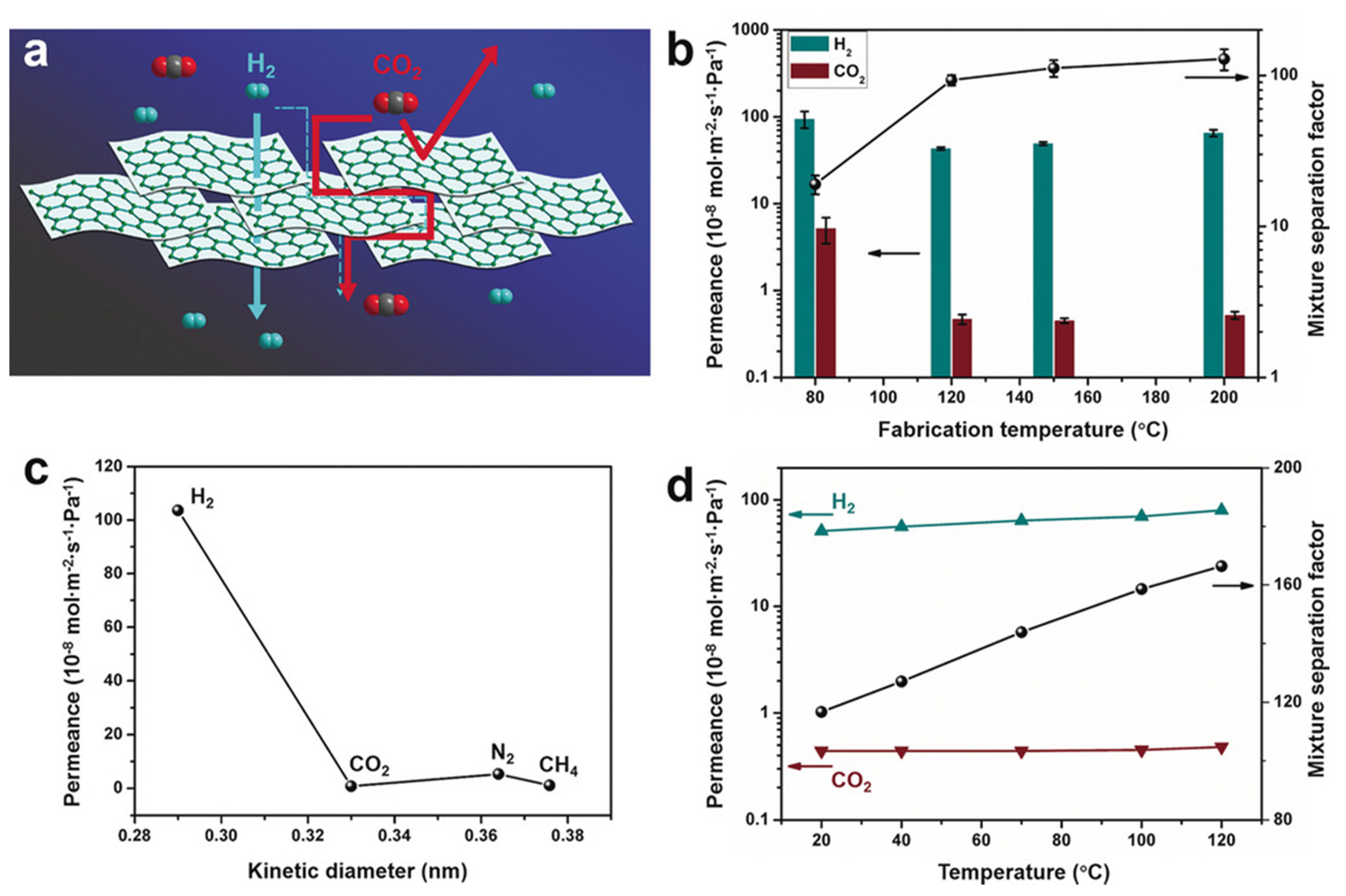
As it was mentioned before, one of the requirements to get excellent separation performance is using ultrathin membranes. In this context, Hou et al. reported the formation of ZIF-8 over APTES- titatina-modified PVDF hollow-fibre membranes with excellent H2 permeance (up to 201 × 10−7 mol m−2s−1Pa−1) and ideal H2/CO2 selectivities [228]. The use of membranes based on MOF nanosheets have been widely used in H2/CO2 gas separation processes since the first report from Yang and coworkers in 2014 [229]. Later on, the same group reported the preparation of sub-10 nm-thick ultrathin membranes based on 2D MOF nano sheets obtained by a novel soft-physical exfoliation strategy (Figure 24). The membrane thickness as well as the size-exclusion influence of the MOF membranes lead to H2 permeance of up to 8 × 10⁻⁷ mol m−2s−1Pa−1 at high temperatures and a H2/CO2 separation factor of 166 [230].
Zhang and coworkers were pioneers in the preparation of highly oriented, continuous, and scalable tubular ZIF nanosheet membranes for H2/CO2 separation using different strategies. In one case, they carried out the ZnO self-condensation by the help of ammonia that acted as a modulator during the direct growth of the membrane. They got to prepare a 50 nm-thickness nanosheet membrane that showed a permeance of H2 of 2.04 × 10⁻⁷ mol m−2s−1Pa−1 and ideal selectivity of 53, 67, and 90 for H2/CO2, H2/N2, and H2/CH4, respectively [231]. In a subsequent report, the presence of GO during the in-situ growth strategy helped to control the orientation growth, obtaining a 200 nm-thickness membrane, which showed excellent H2/CO2 ideal separation selectivity of 106 with a H2 permeance of 1.5 × 10⁻⁷ mol m−2s−1Pa−1 [232]. Very recently, the same group achieved for the first time to synthesise Co-based ZIF nanosheets membrane with a thickness of ca. 57 nm, which reached H2/CO2 selectivity values as high as 58.7 and a H2 permeance of 17.2 × 10⁻⁸ mol m−2s−1Pa−1. In this case, the applied method, based on ligand vapour-phase transformation, allowed controlling the thickness as well as the orientation of the nanosheets during the membrane growth since both issues affect gas separation performance [75]. In a different report, Coronas and coworkers reported preparation of double ZIF membranes inside polyimide P84 hollow fibres. On the inner surface of the hollow fibres, the ZIF-9 layer was firstly crystallised using liquid phase epitaxial (LPE) synthesis with a microfluidic system. Then ZIF-67 or ZIF-8 layer was coated on the ZIF-9 layer by the same method in order to reduce the CO2 adsorption on the ZIF-9 surface. The results show a significant improvement of H2 selectivity and permeance [233].
Liu and coworkers demonstrated how the preparation of highly c-oriented NH2-MIL-125(Ti) membranes resulted in H2/CO2 selectivity values six times higher than those randomly oriented counterparts due to the elimination of grain defects as well as to the decrease of diffusion barriers [57].
In the case of MOF based MMMs, very recently, Urban and coworkers reported the preparation under mild conditions of MMMs based on UiO-66-NH2 and a flexible polymer, which showed excellent H2 separation properties caused by the formation of H-bonding between the amino and carboxylic groups from the constituent materials. The exceptional compatibility between them, allowed obtaining membranes with MOF loads up to 55 wt % and CO2 and H2 permeability of 2494 and 2932 Barrers, respectively. It is a highlight that the gas permeability performance increased 16-fold with respect to the bare polymer and it is maintained over 5300 h of operation at ambient conditions [234].
Very recently Chen et al. prepared tubular MMMs based on MOFs-polymer-tubular ceramic support. In this study, MOFs (NH2-GAU-1 and NH2-MIL-53) nanoparticles were dispersed in solvent with addition of PMMA. Then the mixtures were coated on the organosilica (BTESE) modified ceramic support to form the MMMs. One of the resulting MMMs with 20% NH2-MIL-53 and 80% PMMA loading provide a high H2/CO2 separation factor of 53.1, which is higher than most reported MMMs and higher than the Robeson upper bound limit of gas separation. These results show the high potential application of the MOF-polymer MMMs for H2/CO2 separation [235]. NH2-MIL-53 and polymer (VTECTM) MMMs for H2/CO2 separation have been studied by Musselman et al. as well [236].
The challenge of manufacturing continuous COF membranes has been slightly improved with the introduction of graphene oxide in the preparation process as it will favour the formation of interactions between both materials that gave rise to more stable structures. Ying et al. were pioneers in the preparation of covalent triazine-based framework-1 (CTF-1)/GO ultrathin membranes with H2 permeabilities (1.7 × 10⁻⁶ mol m−2s−1Pa−1) and H2/CO2 selectivity, exceeding the Robeson’s 2008 upper bound [82]. In a similar approach, Kang and coworkers prepared different composited membranes based on GO and TpPa COFs at different ratios, which were tested for H2 purification. The adequate balance between the TpPa-1 COF and the GO allowed reaching a high H2/CO2 selectivity value of 25.57 and a high H2 permeance of 1.067 × 10⁻⁶ mol m−2s−1Pa−1 [83].
Caro and coworkers reported an innovative COF-COF composite membrane formed by the controlled growth of imine-based COF-LZU-1 and azine-based ACOF-1 layers on a porous surface for its application in gas separation. The formation of interlaced pore channels between the two COF layers, gave rise to better selectivity values for H2/CO2, H2/N2, and H2/CH4 than the COFs separately, exceeding the Robeson upper-bound [169].
In the case of COF MMMs, Wang and coworkers integrated a 2D imine based COF into the poly(vinylamine) (PVAm) polymer matrix, which showed CO2/H2 selectivity of 15 and CO2 permeance of 396 GPU at 0.15 MPa and 10 wt % due to the excellent polymer/COF compatibility and the creation of CO2 preferential adsorption sites [124]. In another approach, the high chemical stability of TpBD and TpPa-1 COFs was used by Biswal et al. for the preparation of MMMs that showed high gas permeability for H2, CO2, and CH4 compared to the bare polymers. Particularly, they achieved high hydrogen selectivity from gas mixtures, namely 82.7 for H2/N2 (with TpBD(40%)@PBI-BuI), up to 165.5 for H2/CH4 (with TpPa-1(40%)@PBI-BuI), and 3.9 for H2/CO2 (with TpBD(40%)@PBI-BuI) [141]. Kang et al. demonstrated how the incorporation of the COF NUS-2 into the polybenzimidazole (PBI) polymer matrix gave rise to MMMs with an increase of three orders of magnitude in the H2/CO2 selectivity with respect to the bare polymer, exceeding the upper-bound reported by Robeson in 2008 [149].
Fu et al. reported on the preparation of two MOF/COF composite membranes, which featured exceptional results in gas separation due to the chemical interactions established between the different components at the interface. Principally, they showed H2/CO2 selectivity for [COF-300]-[Zn2(bdc)2(dabco)] and for [COF-300]-[ZIF-8] composites of 12.6 of 13.5, respectively [93].
Kang et al. fabricated a series of COF-GO composite membranes. In addition to the COF’s properties, GO helped to keep the two-dimensional structure of the COF layer. Additionally the rich function groups on the surface of GO interacted with both COF and CO2 for the enhancement of H2 selectivity. The optimal membrane of TpPa-1-30/GO-10 exhibited a high gas separation permeance of 1.067 × 10⁻⁶ mol m−2s−1Pa−1 and a H2/CO2 separation factor of 25.57 [144].

4.1.3. Hydrocarbon Separation

Separation of isomers as well as saturated/unsaturated hydrocarbons with similar physical properties is very important in petroleum refinery, petrochemistry, and natural gas production. Usually these separations are carried out by distillation units, which are extremely costly. So, it is necessary to replace them by energy-efficient and less costly alternative technologies such as the use of membrane separation.
Many MOFs have been reported for hydrocarbon separation [237]. Particularly, the olefin/paraffin separations of ZIF molecular sieve membranes have been reviewed recently by Liu and coworkers [238]. These authors have focused on describing ZIF-based membranes for propylene/propane and ethylene/ethane separations. ZIF-8, whose pore size is between the size of propylene and propane molecules, has been widely studied for this application since the first report in 2012 [239]. Later on, many studies have focused on the effect of the nature of the metal salt as well as membrane fabrication methods used in order to improve the performance of the ZIFs membrane for olefin/paraffin separation [56,240,241,242,243]. For example, the novel membrane synthesis methods all-vapour ligand-induced permselectivation (LIPS) [74] and fast current driven synthesis (FCDS) [244] applied for the preparation of ZIF-8 membranes, showed one of the highest propylene/propane separation factor values (74 and 300, respectively) and propylene permeance (1.6 × 10⁻⁷ and 1.74 × 10⁻⁸ mol Pa−1m−2s−1, respectively). Lin et al. showed the beneficial effect on the separation of C3H6/C3H8 by preparing MMMs with a filler based on ZIF-8, grown on the surface of carbon nanotubes (CNT). The excellent compatibility between the composite filler and the polymer matrix gave rise to enhance in both C3H6 permeability and selectivity [245]. Very recently, Nair and coworkers demonstrated that the incorporation of surface-treated nanoparticles of the zeolite MFI during the growth of ZIF-8 MMM originated propylene/propane separation characteristics that exceed the Robeson upper-bound limits. Particularly, the C3H6 permeability increased dramatically from 371 Barrer in the pure ZIF-8 membrane to 548 Barrer in the ZIF-8/MFI MMM while maintaining the selectivity [246].
Long and coworkers demonstrated how the nanoparticles of Ni2(dobdc) and Co2(dobdc) with a size much lower than 100 nm and with high external surface areas were well-dispersed in the 6FDA-DAM polymer matrix due to the interactions between them and the polymer matrix chains. The results showed improvements in ethylene permeability as well as ethylene/ethane selectivity and membrane stability due to the interactions formed and the decrease in the mobility of polymer chains (Figure 25) [247].
In the case of MOF based MMMs, very recently, Liu et al. managed to control both C3H6/C3H8 permeability and selectivity in ZIF-8/XLPEO (poly(ethylene oxide), XLPEO) MMM by varying the filler loading as well as the molar ratio of pre-polymers precursors used in the preparation of XLPEO [101].
COF membranes for hydrocarbon recovery have also been studied. Kharul and coworkers were pioneers in the preparation of TpPa-1@SBR (styrene-butadiene rubber, SBR) TFC membranes onto a polyacrylonitrile (PAN) support for propylene/propane separation. The excellent compatibility between the COF and the polymer matrix, allowed obtaining flexible and defect-free TFC membranes with filler loading up to 70 wt %. However, the best performance was reached at 50 wt % with an increase of ca. 8-fold and ca. 12-fold for propylene and propane permeance, respectively. Likewise, slight changes in C3H6/N2 and C3H8/N2 reverse selectivity (20 and 15, respectively) were found for TpPa-1(50)@SBR [248].
MOFs and COFs membranes used for gas separation demand a defect free and a good interface between frameworks and subtract. In some cases, such as CO2 removal, the presence of polar groups can enhance the chemical interaction of the membrane with CO2 and increase the selectivity. For all gas separations, the chosen best pore size is very important for the best compromise between permeability and selectivity.

4.2. Liquid Separation

In this section, different types of separation carried out in liquid phase are addressed. It is highlighted that for this application, membrane stability under the operative conditions is of great importance. As it is well known some types of MOFs and COFs present poor stability in water and acid/basic solutions, which limits their applicability [249]. Recently, Van der Bruggen and coworkers have gathered the main principles for the selection of MOFs to prepare membranes for liquid separation [32]. Here, we will consider MOF and COF membranes employed especially for water treatment, organic solvent nanofiltration, and pervaporation.

4.2.1. Water Treatment

There is a great interest in the development of new technologies for waste water treatment as well as for the desalination of sea water, since the current demand for potable water is increasing [250,251]. Some of the waste that has to be removal from water are salts, metallic ions, dyes, nanoparticles, and organic chemicals. Usually, they are removed by filtration with polymeric membranes, which offer low cost and energy consumption. However, polymer materials do not always meet the necessary requirements of both high permeability and rejection, which limits their use. Kadhom et al. and Lee et al. reviewed MOFs for the membrane desalination and water treatment, showing some remarkable results improving membranes performance [30,252]. Very recently, an example of soluble drug removal using HKUST-1 and ZIF-93 based membranes was reported by Téllez and coworkers. Particularly, these authors studied the elimination of Diclofenac and Naproxen from an aqueous solution having a water permeance in the case of HKUST-1 of 33.1 L m−2h−1bar−1 and 24.9 L m−2h−1bar−1, respectively, with rejections over 98% [253].
In the case of COFs, Caro and coworkers reported a stable 2D imine COF-LZU1 membrane grown on alumina tubes by in situ synthesis for dye separation present in water or saline solutions. This excellent 400 nm thick-membrane showed water permeance values (ca. 760 L m−2h−1MPa−1) higher than commercial and other reported nanofiltration membranes as well as rejection rates > 90% for dyes larger than 1.2 nm (Figure 26) [78]. Other authors also reported on the preparation of COF based membrane for dye separation showing interesting results [254]. Very recently, Wang and coworkers managed to prepare ultra and nanofiltration membranes based on an imine-linked COF by the modification of the synthesis conditions. These membranes showed high separation efficiencies for dyes from water or organic solution as well as for proteins solutions even higher than other reported membranes prepared from MOFs [255]. In another approach, Xu et al. made use of the excellent hydrolytic and chemical properties of the COFs TpPa-2 for the preparation of a 0.2 wt % TpPa-2@polysulfone (PSf) MMM that showed a significantly high improvement of the performance of the membranes in the removal of organic foulants from water [256]. Similar to MOFs, some COF based membranes have also been tested for water desalination. For example, Wu and coworkers reported a thin-film nanocomposite (TFN) membrane formed by the SNW-1 COF dispersed in polyamide (PA) and supported on a polyether sulfone (PES) substrate, which doubled the flow of water with respect to the pristine membrane and showed a Na2SO4 rejection above 80% [87].
The permeability during the water treatment mainly depends on the hydrophilicity of the membrane, which could be improved by introducing proper MOFs or COFs structure and also by adding the hydrophilic function on the membrane surface. As for the rejection ability, it is related to the pore size of the membrane as well as the charge of the membrane in the case of salt rejection.

4.2.2. Organic Solvent Nanofiltration

Organic solvent nanofiltration (OSN), also known as solvent resistant nanofiltration (SRNF), is a technology that allows the separation of organic mixtures at the molecular level through the application of a gradient of pressure over a membrane. This technique is used in most processes of food, bio-refinery, petrochemical, and pharmaceutical industries. Interesting reviews have been reported describing the OSN technique by Marchetti et al. and Vandezande et al. [183,257]. An OSN membrane should be robust and stable under operative conditions as well as showing high solvent permeance and high solute rejection. In 2017, Wang and coworkers discussed different polymer based membranes for this application [258]. MOFs and COFs are both chemically stable and structurally well-defined, which could enhance the long-term stability and selectivity for organic solvent nanofiltration membranes.
Livingston et al. prepared thin-film nanocomposite (TFN) membranes with a polyamide (PA) thin-film layer on top of cross-linked polyimide porous supports and a range of 50–150 nm pore size metal-organic framework (MOF) nanoparticles (ZIF-8, MIL-53(Al), NH2-MIL-53(Al), and MIL-101(Cr)) via interfacial polymerisation. TFN membrane organic solvent nanofiltration performance was evaluated by solvent permeances (methanol (MeOH) and tetrahydrofuran (THF)) and rejection of styrene oligomers (PS). MeOH and THF permeance increased compared to the same membranes without MOFs, whereas the PS rejection remained higher than 90%. This study showed solvents permeances increased with increasing pore size and porosity of the MOF [259].
Thin film nanocomposite membranes of PA/ZIF-8 (or ZIF-67) @PI has been developed by Coronas et al. via dip-coating of ZIF suspensions on the polyimide supports and then following by interfacial polymerisation of a ultra-thin polyamide layer on the top of the ZIF layer. One of the optimised membrane of PA/ZIF-8@PI with one time ZIF-8 dip-coating in methanol shows 150% improvement of permeance and 90% rejection of sunset yellow (SY) [260].
Banerjee and coworkers reported two self-standing and highly stable COF membranes (M-TpBD and M-TpTD) that were tested for the removal of solutes with molecular dimensions larger than 1 nm from aqueous or organic solvents such as dyes, active pharmaceutical ingredients (APIs), and food additives. Moreover, the membranes featured high selectivity towards polar organic solvents, especially in the case of M-TpTD with an acetonitrile flux 2.5 times order magnitude higher than the reference polyamide NF membranes (Figure 27) [79]. In another approach, the same group prepared nanofiltration membranes based on defect-free and self-standing COF thin films. Tp-Bpy, Tp-Azo, Tp-Ttba, and Tp-Tta were chosen to prepare the thin film composite membranes with different pore size via liquid−liquid interfacial polymerisation and then transform to a polyester-3329 nonwoven porous fabric support. The optimised thickness Tp-Bpy membrane exhibited excellent permeance toward both aprotic and protic solvents such as acetonitrile, water, ethanol, and methanol. For solute rejection, Tp-Bpy exhibited high rejection values: 94% for brilliant blue-G (BB), 80% for Congo red (CR), 97% for acid fuchsin (AF), and 98% rhodamine B (RH) [88].
Very recently, Hu and coworkers prepared a new TFN membrane for organic solvent nanofiltration with COFs (SNW-1) nanoparticles in the polyamide skin layer by interfacial polymerisation. The membrane showed improved hydrophilicity and solvent permeance as well as an increase of Rhodamine B rejection (up to 99.4%) compared to COFs-free membranes. The TFN OSN membranes exhibited an excellent N, N-dimethylformamide (DMF) solvent resistance over 100 days. The cross-flow filtration with the TFN membranes using the Rose Bengal/DMF solution at ambient temperature over 7 days, separation performance was maintained. These properties show a strong potential in OSN applications [261].
A novel porous covalent organic triazine-piperazine based TFN membrane (CTP membrane) for OSN was prepared by Peinemann et al. The porous CTP skin layer provided stable porous robust structure, large surface area, well-defined pore topology, and solvent durability. The membrane exhibited excellent separation properties such as selective dye rejection (Reactive black-5, 96.7%) and salt rejection (Na2SO4, 91.3%). Such a membrane would be a promising candidate for NF applications [262].
Shinde et al. prepared a 2D COF membrane by the LB method, which showed permeabilities 5–100 times higher than amorphous membranes and other similar reported materials. The high crystallinity of TFP-DHF 2D COF membrane provided a sharp molecular sieving and long-term rejection of dye molecules in different solvents with an molecular weight cut-off (MWCO) value of approximately 900 Da (Figure 28) [92].
In summary, membrane pore size is the critical factor for separation capacity facing guest molecules. Additionally the stability of MOFs or COFs as well as the substrate in the working solvent is also a necessary requirement for OSN membranes.

4.2.3. Pervaporation

Pervaporation separation is a potential technique for liquid small molecule mixture separation in pharmaceutical and chemical industries. Compare to conventional techniques such as distillation, pervaporation is an energy-saving, and a highly selective technique. MOFs and COFs have good organic compatibility and multi-functionality, which make them a good candidate for the preparation of the pervaporation composite membrane.
Jia et al. have first introduced Zr-MOFs (UiO-66, UiO-66-OH, UiO-66-(OH)2, and UiO-67) into polymeric membrane (PVA) for ethanol dehydration via pervaporation. The interactions between Zr-MOFs and PVA matrix and pervaporation performances of MMMs were enhanced successfully by introducing of -OH groups on the organic ligands. For the optimal 1.0 wt.% loading of UiO-66-(OH)2, the water permeance and selectivity increase by 24% and 10% while the swelling degree decreased by 28% in comparison with that of the pristine membrane, making it a potential membrane for ethanol dehydration [263].
Towards industry application, hollow fibre with high packing density could be an ideal substrate for pervaporation mixed-matrix composite membrane. Jin et al. fabricated a novel ceramic hollow fibre supported mixed-matrix composite membrane made of MAF-6 nanoparticles and poly (ether-block-amide) (PEBA) via a facile dip-coating approach. Total flux of 4446 g m−2 h and separation factor of 5.6 (feed: 5 wt % ethanol/water, 60 °C) was achieved as optimising result, which showed great advantages over the reported PEBA-based membranes for ethanol/water separation by pervaporation [173].
Recently Steunou et al. prepared ZIF-8 MMM by casting the ZIF-8 collides on the support membrane for isopropanol pervaporation. ZIF-8 collide suspensions were obtained by grafting polyethylene glycol (PEG) at the surface of ZIF-8 nanoparticles (NPs) and then stabilising PEG-g-ZIF-8 NPs by poly(vinyl alcohol) (PVA) to provide a stable casting suspension. Due to the molecular sieving effects of ZIF-8 and the good interfacial properties of the membrane, the pervaporation flux of the MMM was 11 times higher than that of the pure PVA membrane. These MMMs presented a high separation factor up to 7326 [148].
Apart from the alcohol/water pervaporation, other organic liquid mixtures have also been separated by pervaporation using MOF membranes. Caro et al. firstly studied the pervaporation of n-hexane, benzene, and mesitylene as a pure component and binary mixtures on a supported ZIF-8 membrane. The ZIF-8 membranes were prepared by secondary growth on the a-Al2O3 disc membranes. For n-hexane/mesitylene mixture, molecular sieving took place and the n-hexane flux was reduced by pore entrance blocking of increasing concentration of mesitylene [264].
Lin et al. prepared MOF-5 membranes by dip-coating of MOF-5 suspension and secondary growth. Then they studied the pervaporation fluxes and separation factors for toluene, o-xylene, and 1,3,5-triisopropylbenzene (TIPB) pure component and also for 50:50 (mass composition) binary mixtures (toluene/TIPB, o-xylene/TIPB, and toluene/o-xylene) through MOF-5 membranes. Due to the adsorption affinity of guest molecule towards MOF-5 and kinetic diameter of the permeating species, high separation factors for toluene/TIPB, and o xylene/TIPB mixture showed the possibility of separation of these species by pervaporation. However the fouling of the MOF membrane is the main limitation obstacle for their application in organic liquid pervaporation [265].
Jiang et al. used an imine-linked COF TpBD hollow nanospheres (H-TpBD) and sodium alginate (SA) matrices to fabricate water-selective hybrid membranes. The H-TpBD nanospheres provided rich hydrophilic groups and favourable compatibility that rendered the membranes with high water-selective permeability and long-term stability. The optimal performance of the hybrid membranes exhibited a permeation flux of 2170 g m−2h−1 and separation factor of 2099 when used for dehydrating 90 wt % ethanol aqueous solution at 76 °C [173].
The others similar ethanol/water pervaporation study based on the COF MMM were using different COFs (SNW-1 or COF TpHZ) and also different matrixes such as sodium alginate and poly(ether sulfone) [177,266].
Apart from the dehydration of ethanol via pervaporation, the dehydration of butanol via pervaporation using COFs based MMM were also investigated [267]. Jiang et al. reported a COF membrane through a mixed-dimensional assembly of 2D COF (Schiff-base-type COF TpTGCl) nanosheets and 1D cellulose nanofibers (TEMPO-oxidized CNFs). The COF TpTGCl is chemically stable and can be easily exfoliated to obtain nanosheets. Meanwhile, the intrinsic positive charge of guanidinium units on the TpTGCl framework could help their assembly with negatively charged TEMPO-oxidized CNFs. The membrane enhanced the water adsorption and transport and also provided molecular sieving for improving water solubility and selectivity. The results show a significant improvement of flux (8.53 kg m−2h−1) with and separation factor (3876) for n-butanol dehydration [161].
Zhang and coworkers reported hydrazone-linked covalent organic-frameworks (COF-42) based membrane for butanol dehydration. The membranes were prepared by dip-coating with a homogeneous suspension of COF-42 and polydimethylsiloxane (PDMS). Since the hydrophilic C=O function is present on the structure of the COF-42, water molecule diffusion was affected and slowed down on the inner wall. The resultant COF-based membrane showed an enhancement of the permeability and selectivity of butanol. The optimal membrane exhibits a high separation factor of 119.7 with a total flux of 3306.7 g m−2h−1. A “dual membrane process” by coupling the COF-based membrane with a commercial NaA molecular sieving membrane, a 5 wt % feed solution could reach 99.2 wt %, which could be used as the fuel-grade bioalcohol. The high selectivity COF-based membranes could provide a possible non-distillation pathway for biobutanol production [168].
Additionally, COF-LZU1 particles and PEBA have been used for preparing n-butanol dehydration membrane. They showed good permeation flux, excellent running stability, and significant improvement of selectivity [267].
Beside the previous applications, Jiang et al. used COF (SNW-1) based membranes for gasoline pervaporation desulfurisation. The membranes were prepared by spin-coating of casting solutions containing Ag+ loaded SNW-1 and Pebax on the Polysulfone (PSf) membranes. The organic nature of SNW-1 optimised the interfacial affinity between filler and polymer, and rendered appropriate free volume properties, molecular sieving ability as well as stability. The membranes displayed enhanced permeation flux, selectivity, and also an anti-swelling property in the separation of the thiophene/n-octane mixture. The optimum performance towards thiophene concentration of 1312 ppm under 60 °C, was achieved with a permeation flux of 16.35 kg m−2h−1 and enrichment factor of 6.8, which was increased by 78.5% and 30.0% compared with pure Pebax membranes [268].
Membrane pore size is also the main factor for pervaporation application. Some favourable functionalities can also enhance the flux or the selectivity.

4.3. Fuel Cells

Polymer electrolyte membranes (PEM) are the key component of fuel cells (FCs), which represent a clean energy alternative. An ideal ion exchange membrane, must meet the following requirements [269]: (a) high ionic conductivity; (b) zero electronic conductivity; (c) low permeability to avoid cross-over; (d) good chemical and thermal stability under fuel cell operating conditions; (e) thin-film processability and stability; (f) high lifetime; and (g) low cost. One of the most common materials used as PEM is Nafion [270,271], developed by DuPont [272], which can reach conductivities values of 10−1 S cm−1 after its humectation. However, the problems derived from its high cost of production as well as its dehydration at elevated temperatures resulting in a loss of conductivity. To overcome these problems an alternative membrane is required. MOFs and COFs have become ideal candidates for proton conducting applications since they provide an opportunity to characterise the ionic conduction pathway and mechanism, which is difficult to get with other solid electrolytes due to their amorphous nature [193]. Many studies report the design and synthesis of proton-conducting MOFs and COFs, their properties and their operative conditions [273,274,275,276,277,278,279]. The conductivity properties of these materials are usually determined by electrochemical measurements of the processed pellets, which often show poor mechanical flexibility and high thickness limiting their performance under real proton-exchange membrane fuel cell (PEMFC) operating conditions. Therefore, free-standing, flexible membranes based on polycrystalline MOFs and COFs are required. However, so far no example has been reported on the use of MOF membrane directly as a solid electrolyte in a FC. However, Banerjee and coworkers pioneered the use of COFs as solid electrolytes for H2/O2 fuel cells under real operating conditions. They showed how a bipyridine functionalised COF loaded with H3PO4 improved both the mechanical and the proton conductivity of the resulting materials. As mentioned before the physical characteristics of the generated COF pellet, limited its performance in the fuel cell [192]. In this regard, Montoro et al. were able to prepare a quasi-transparent and flexible film from an imine-based COF that showed high conductivity values (1.1 × 10⁻² S cm−1 at 323 K). The integration of this novel film-membrane into a single H2/O2 PEMFC gave rise to a maximum power density peak at 12.95 mW cm−2 and a maximum current density of 53.1 mA cm−2 [189]. In a subsequent report, Banerjee and coworkers prepared three different free-standing, flexible, porous COF membranes using an amino p-toluene sulfonic acid that exhibited superprotonic conductivity values. Particularly, PTSA@TpAzo showed very high proton conducting values (7.8 × 10⁻² S cm−1 at 80 °C under 95% RH) and one of the highest power densities so far reported for crystalline porous organic polymers (24 mW cm−2) [80].
The use of MMMs as a solid electrolyte in FCs has been highly exploited since they combine the advantages of the polymeric matrix with those from organic/inorganic filler materials [280]. Nafion, sulfonated poly(ether ether ketone) SPEEK, polybenzimidazole (PBI), poly(vinylidene fluoride) (PVDF), and poly(vinylalcohol) (PVA) are some of the most used polymers in the preparation of MMM for this application. The integration of fillers into these polymers is expected to provide better performances due to the synergistic effects of the functional components. Apart from these polymers, Guo et al. fabricated a composite membrane using DNA threaded to ZIF-8 (Figure 29). The low methanol permeability (1.25 × 10⁻⁸ cm2 s−1) as well as the high proton conductivity (0.17 S cm−1 at 75 °C, under 97% RH) of the DNA@ZIF-8 membrane allowed for the first time, its performance as solid electrolyte in methanol fuel cell leading to a maximum power density of 9.87 mW cm−2. The activation energy values obtained (from 0.40 to 0.86 eV) indicated that the proton conductivity follows the Grotthuss mechanism (≤0.4 eV) [281].
In some cases, additives such as graphene oxide (GO), phytic acids, or phosphoric acid are needed to improve the values of ionic conductivity since they can provide additional proton-pathways. For example, Wu et al. prepared a MMM based on Nafion and a zeolitic imidazolate framework–graphene oxide composite (ZIF-8@GO). This hybrid membrane showed better thermal stability as well as an increase of the proton conductivity with the temperature in comparison with recast Nafion. Specifically, at 120 °C and 40% RH the MMM showed conductivity values of 0.28 S cm−1 at 120 °C whereas recast Nafion 0.005 S cm−1 (Figure 4) due to a synergetic effect of ZIF-8 and GO in promoting proton transfer through a Grotthuss mechanism [282]. In the case of MOFs, an excellent review has been recently published by Escorihuela et al. describing MOF-based MMM used as PEMs for fuel cell applications [283]. As they report, some of the MOFs used for this application are MIL-101 [284,285], MIL-101-SO3H [286,287,288], UiO-66-NH2 [289,290], UiO-66-SO3H [289,290,291], MOF-801 [292], ZIF-8 [282,293,294], ZIF-67 [287], MIL-53-Al [295], and NH2-MIL-53 [296]. However, not all of them have been tested under real operating conditions.
Jiang and coworkers prepared a nanohybrid membrane from SPEEK and MIL-101 with phosphotungstic acid encapsulated inside the pore that showed apart from an increase of the thermal stability and enhancement of the proton conductivity with respect to the pristine material. Particularly, for filler loads of 9 wt % the nanohybrid membrane HPW@MIL-101 (9 wt %) exhibited a proton conductivity of 0.272 S cm−1 at 65 °C and 100% RH and the pristine SPEEK membrane (0.187 S cm−1). Likewise, power density curves obtained after the H2/O2 single cell performance at 55% RH and 60 °C of SPEEK/HPW@MIL-101 (9 wt %) PEM was in the same order as Nafion 212 (224 mW cm−2) and three times higher (235 mW cm−2) than that of pristine SPEEK membrane (79 mW cm−2) [285]. Zang and coworkers studied the effect of MMM based on chitosan (CS) and MIL-101 its derivatives (S-MIL-101, and acids@MIL-101) in the proton conductivity and interface compatibility. The results showed that the presence of acids inside the MOF pores increase the proton conductivity and better cell performance with CS/H2SO4@MIL-101-8 with the highest current density (368 mA cm−2) and power density (146 mW cm−2) similar to the reported CS-based PEM [288]. Tsai et al. prepared two MMM based on Nafion and the 1-D channel microporous MOFs CPO-27(Mg) and MIL-53(Al). The ability of water retention of this MOF leads to better performance than the recast Nafion in terms of proton conductivity and power densities. Specifically, PEM based on CPO-27(Mg) showed a maximum power density of 853 mW cm−2 at 50 °C and 568 mW cm−2 at 80 °C under 15% RH conditions [295].
In the case of COFs, MMMs prepared from PVDF and the COFs NUS-9 and NUS-10 showed proton conductivities values up to 1.58 × 10⁻² Scm−1 and 5.16 × 10⁻³ Scm−1, respectively, due to the presence of pendent sulfonic acid groups into the 1D nanoporous channels of the COFs. The presence of these groups facilitates the adsorption of water molecules as well as serves as favourable pathways for proton conduction following a Grotthuss mechanism [126].
Jiang and coworkers showed the fabrication of a zwitterion-functionalised COF (Z-COF) integrated into Nafion. The presence of both ammonium and sulfonic acid groups in the Z-COF gives rise to an enhancement of water retention property as well as proton conductivity values in the range of 0.22 S cm−1 at 80 °C and 100% RH at 10 wt % of Z-COF, which was 57.1% higher than that of recast Nafion membrane. Likewise, Nafion/Z-COF with loads of 45.7 wt % showed the maximum power density of single fuel cell at 80 °C and 50% RH superior also to the recast Nafion membrane [191].
Yin et al. prepared a composite membrane based on Nafion and phosphoric acid-loaded schiff base COF networks with intrinsic amino groups and micropores (H3PO4@SNW-1). The incorporation of acid groups into the COFs favoured its compatibility with the polymer matrix, optimised hydrophilic domains and generated proton transfer sites. The maximum value of proton conductivity (0.137 S cm−1 at 30 °C, 100% RH) and power density was obtained for a load of 15% [190].
In summary, functionalities provided by the MOFs/COFs structures that could increase the interaction with ions (protons) are highly promising to improve the performance of polymer electrolyte membranes. At the same time, well oriented nanopores could serve as nanochannel for ions. Additionally, membrane stability under the working condition of a fuel cell is evidently required.

5. Conclusions

MOFs and COFs are an emerging class of crystalline porous materials consisting of orderly arranged pore structures, with high porosity and large surface area. Since various versatile organic linkers could be used in the synthesis of MOFs and COFs, their pore size, shape, and functionalities could be tailored relatively easy. All these aspects make MOFs and COFs ideal candidates for design and synthesis of membranes for separation technologies. Different preparation methods of MOF and COF membranes including free-standing membranes, thin film, MOF/COF composites, and mixed matrix membranes were analysed. Additionally, the main techniques used for characterisation of COF and MOF membranes were summarised. Furthermore, the limitations and advantages of each type of membrane and characterisation methods were also discussed. Finally, the most recent work reported on the use of MOF and COF-based membranes for gas separation (CO2 recovery, H2 purification and recovery, and hydrocarbon separation), liquid separation (water treatment, organic solvent nanofiltration, and pervaporation), and in fuel cells were reviewed.

Author Contributions

Conceptualization, C.M. and M.S.; writing—Original draft preparation, M.F., C.M. and M.S.; writing—review and editing, C.M. and M.S.; supervision, C.M. and M.S.; project administration, M.S.; funding acquisition, M.S. All authors have read and agreed to the published version of the manuscript.

Funding

This research was funded by China Scholarship Council (CSC), grant number 201708070001.

Acknowledgments

MF acknowledges the financial support of China Scholarship Council (CSC), grant number 201708070001. CNRS-INC is thanked for the post-doctoral support of CM. The Regional Government of Madrid and Universidad Autonoma de Madrid are acknowledged for the PRICIT project (MemCat-SI1/PJI/2019-00505). We also thank Anne Julbe for her help and advice during preparation of this manuscript.

Conflicts of Interest

In accordance with our policy on Conflicts of interest please ensure that a conflicts of interest statement is included in your manuscript here. Please note that this statement is required for all submitted manuscripts. If no conflicts exist, please state that “There are no conflicts to declare”.

References

  1. Aptel, P.; Armor, J.; Audinos, R.; Baker, R.W.; Bakish, R.; Belfort, G.; Bikson, B.; Brown, R.G.; Bryk, M.; Burke, J.J.; et al. Terminology for membranes and membrane processes (IUPAC Recommendations 1996). J. Membr. Sci. 1996, 120, 149–159. [Google Scholar] [CrossRef]
  2. Ter Minassian-Saraga, L.; Adler, M.; Barraud, A.; Churaev, N.V.; Eaton, D.F.; Kuhn, H.; Misono, M.; Platikanov, D.; Ralston, J.; Silberberg, A.; et al. Thin films including layers: Terminology in relation to their preparation and characterization. IUPAC recommendations 1994. Thin Solid Films 1996, 277, 7–78. [Google Scholar] [CrossRef]
  3. Based, C.; Based, C. Membrane Classification and Membrane Operations. In Nanomaterial and Polymer Membranes; Elsevier: Amsterdam, The Netherlands, 2016; pp. 55–82. ISBN 9780128047033. [Google Scholar]
  4. Mulder, J.; Mulder, M. Basic Principles of Membrane; Kluwer Academic Publishers: Berlin, Germany, 1996. [Google Scholar]
  5. Pinnau, I. Membrane Preparation. Encycl. Sep. Sci. 2000, 1755–1764. [Google Scholar] [CrossRef]
  6. Shekhah, O.; Liu, J.; Fischer, R.A.; Wöll, C. MOF thin films: Existing and future applications. Chem. Soc. Rev. 2011, 40, 1081–1106. [Google Scholar] [CrossRef]
  7. Yaghi, O.M. Reticular Chemistry—Construction, Properties, and Precision Reactions of Frameworks. J. Am. Chem. Soc. 2016, 138, 15507–15509. [Google Scholar] [CrossRef] [PubMed] [Green Version]
  8. Furukawa, H.; Cordova, K.E.; O’Keeffe, M.; Yaghi, O.M. The chemistry and applications of metal-organic frameworks. Science (80) 2013, 341, 1230444–1230456. [Google Scholar] [CrossRef] [PubMed] [Green Version]
  9. Ockwig, N.W.; Delgado-Friedrichs, O.; O’Keeffe, M.; Yaghi, O.M. Reticular Chemistry: Occurrence and Taxonomy of Nets and Grammar for the Design of Frameworks. Acc. Chem. Res. 2005, 38, 176–182. [Google Scholar] [CrossRef] [Green Version]
  10. Yaghi, O.M.; O’Keeffe, M.; Ockwig, N.W.; Chae, H.K.; Eddaoudi, M.; Kim, J. Reticular synthesis and the design of new materials. Nature 2003, 423, 705–714. [Google Scholar] [CrossRef]
  11. Yaghi, O.M.; Li, G.; Li, H. Selective binding and removal of guests in a microporous metal-organic framework. Nature 1995, 378, 703–706. [Google Scholar] [CrossRef]
  12. Kirchon, A.; Feng, L.; Drake, H.F.; Joseph, E.A.; Zhou, H.C. From fundamentals to applications: A toolbox for robust and multifunctional MOF materials. Chem. Soc. Rev. 2018, 47, 8611–8638. [Google Scholar] [CrossRef]
  13. Côté, A.P.; Benin, A.I.; Ockwig, N.W.; O’Keeffe, M.; Matzger, A.J.; Yaghi, O.M. Porous, Crystalline, Covalent Organic Frameworks. Science (80) 2005, 310, 1166–1170. [Google Scholar] [CrossRef] [Green Version]
  14. Zhou, H.-C.; Long, J.R.; Yaghi, O.M. Introduction to Metal−Organic Frameworks. Chem. Rev. 2012, 112, 673–674. [Google Scholar] [CrossRef] [PubMed]
  15. Moghadam, P.Z.; Li, A.; Wiggin, S.B.; Tao, A.; Maloney, A.G.P.; Wood, P.A.; Ward, S.C.; Fairen-Jimenez, D. Development of a Cambridge Structural Database Subset: A Collection of Metal-Organic Frameworks for Past, Present, and Future. Chem. Mater. 2017, 29, 2618–2625. [Google Scholar] [CrossRef]
  16. Rubio-Martinez, M.; Avci-Camur, C.; Thornton, A.W.; Imaz, I.; Maspoch, D.; Hill, M.R. New synthetic routes towards MOF production at scale. Chem. Soc. Rev. 2017, 46, 3453–3480. [Google Scholar] [CrossRef] [PubMed] [Green Version]
  17. Ding, S.Y.; Wang, W. Covalent organic frameworks (COFs): From design to applications. Chem. Soc. Rev. 2013, 42, 548–568. [Google Scholar] [CrossRef] [PubMed]
  18. Lohse, M.S.; Bein, T. Covalent Organic Frameworks: Structures, Synthesis, and Applications. Adv. Funct. Mater. 2018, 28, 1–71. [Google Scholar] [CrossRef] [Green Version]
  19. Sumida, K.; Rogow, D.L.; Mason, J.A.; Mcdonald, T.M.; Bloch, E.D.; Herm, Z.R.; Bae, T.; Long, R. Carbon Dioxide Capture in Metal-Organic Frameworks. Chem. Rev. 2012, 2, 724–781. [Google Scholar] [CrossRef] [PubMed]
  20. Fujie, K.; Kitagawa, H. Ionic liquid transported into metal-organic frameworks. Coord. Chem. Rev. 2016, 307, 382–390. [Google Scholar] [CrossRef]
  21. Wen, Y.; Zhang, J.; Xu, Q.; Wu, X.T.; Zhu, Q.L. Pore surface engineering of metal–organic frameworks for heterogeneous catalysis. Coord. Chem. Rev. 2018, 248–276. [Google Scholar] [CrossRef]
  22. Xu, Y.; Li, Q.; Xue, H.; Pang, H. Metal-organic frameworks for direct electrochemical applications. Coord. Chem. Rev. 2018, 376, 292–318. [Google Scholar] [CrossRef]
  23. Shah, M.; McCarthy, M.C.; Sachdeva, S.; Lee, A.K.; Jeong, H.K. Current status of metal-organic framework membranes for gas separations: Promises and challenges. Ind. Eng. Chem. Res. 2012, 51, 2179–2199. [Google Scholar] [CrossRef]
  24. Hu, Z.; Deibert, B.J.; Li, J. Luminescent metal-organic frameworks for chemical sensing and explosive detection. Chem. Soc. Rev. 2014, 43, 5815–5840. [Google Scholar] [CrossRef] [PubMed] [Green Version]
  25. Yi, F.; Chen, D.; Wu, M.; Han, L.; Jiang, H. Chemical Sensors Based on Metal – Organic Frameworks. Chempluschem 2016, 81, 675–690. [Google Scholar] [CrossRef] [PubMed]
  26. Lei, J.; Qian, R.; Ling, P.; Cui, L.; Ju, H. Design and sensing applications of metal – organic framework composites. Trends Anal. Chem. 2014, 58, 71–78. [Google Scholar] [CrossRef]
  27. Giménez-Marqués, M.; Hidalgo, T.; Serre, C.; Horcajada, P. Nanostructured metal-organic frameworks and their bio-related applications. Coord. Chem. Rev. 2016, 307, 342–360. [Google Scholar] [CrossRef]
  28. Rodríguez-San-Miguel, D.; Zamora, F. Processing of covalent organic frameworks: An ingredient for a material to succeed. Chem. Soc. Rev. 2019, 48, 4375–4386. [Google Scholar] [CrossRef]
  29. Li, W. Metal–organic framework membranes: Production, modification, and applications. Prog. Mater. Sci. 2019, 100, 21–63. [Google Scholar] [CrossRef]
  30. Kadhom, M.; Deng, B. Metal-organic frameworks ( MOFs ) in water filtration membranes for desalination and other applications. Appl. Mater. Today 2018, 11, 219–230. [Google Scholar] [CrossRef]
  31. Kang, Z.; Fan, L.; Sun, D. Recent advances and challenges of metal-organic framework membranes for gas separation. J. Mater. Chem. A 2017, 5, 10073–10091. [Google Scholar] [CrossRef]
  32. Li, X.; Liu, Y.; Wang, J.; Gascon, J.; Li, J.; Van Der Bruggen, B. Metal-organic frameworks based membranes for liquid separation. Chem. Soc. Rev. 2017, 46, 7124–7144. [Google Scholar] [CrossRef]
  33. Liu, Y.; Ban, Y.; Yang, W. Microstructural Engineering and Architectural Design of Metal–Organic Framework Membranes. Adv. Mater. 2017, 29, 1–17. [Google Scholar] [CrossRef] [PubMed]
  34. Seoane, B.; Coronas, J.; Gascon, I.; Benavides, M.E.; Karvan, O.; Caro, J.; Kapteijn, F.; Gascon, J. Metal-organic framework based mixed matrix membranes: A solution for highly efficient CO2 capture? Chem. Soc. Rev. 2015, 44, 2421–2454. [Google Scholar] [CrossRef] [PubMed] [Green Version]
  35. Yuan, S.; Li, X.; Zhu, J.; Zhang, G.; Van Puyvelde, P.; Van der Bruggen, B. Covalent organic frameworks for membrane separation. Chem. Soc. Rev. 2019, 48, 2665–2681. [Google Scholar] [CrossRef] [PubMed]
  36. Zhang, C.; Wu, B.-H.; Ma, M.-Q.; Wang, Z.; Xu, Z.-K. Ultrathin metal/covalent–organic framework membranes towards ultimate separation. Chem. Soc. Rev. 2019. [Google Scholar] [CrossRef]
  37. Liu, Y.; Ng, Z.; Khan, E.A.; Jeong, H.K.; Ching, C.; Lai, Z. Synthesis of continuous MOF-5 membranes on porous α-alumina substrates. Microporous Mesoporous Mater. 2009, 118, 296–301. [Google Scholar] [CrossRef]
  38. Qiu, S.; Xue, M.; Zhu, G. Metal-organic framework membranes: From synthesis to separation application. Chem. Soc. Rev. 2014, 43, 6116–6140. [Google Scholar] [CrossRef]
  39. Bux, H.; Liang, F.; Li, Y.; Cravillon, J.; Wiebcke, M.; Caro, J. Zeolitic Imidazolate Framework Membrane with Molecular Sieving Properties by Microwave-Assisted Solvothermal Synthesis. J. Am. Chem. Soc. 2009, 131, 16000–16001. [Google Scholar] [CrossRef]
  40. Li, Y.-S.; Liang, F.-Y.; Bux, H.; Feldhoff, A.; Yang, W.-S.; Caro, J. Molecular Sieve Membrane: Supported Metal-Organic Framework with High Hydrogen Selectivity. Angew. Chem. Int. Ed. 2010, 49, 548–551. [Google Scholar] [CrossRef]
  41. Huang, A.; Dou, W.; Caro, J. Steam-stable zeolitic imidazolate framework ZIF-90 membrane with hydrogen selectivity through covalent functionalization. J. Am. Chem. Soc. 2010, 132, 15562–15564. [Google Scholar] [CrossRef]
  42. Huang, A.; Bux, H.; Steinbach, F.; Caro, J. Molecular-Sieve Membrane with Hydrogen Permselectivity: ZIF-22 in LTA Topology Prepared with 3-Aminopropyltriethoxysilane as Covalent Linker. Angew. Chem. Int. Ed. 2010, 49, 4958–4961. [Google Scholar] [CrossRef]
  43. Wang, N.; Liu, Y.; Qiao, Z.; Diestel, L.; Zhou, J.; Huang, A.; Caro, J. Polydopamine-based synthesis of a zeolite imidazolate framework ZIF-100 membrane with high H2/CO2 selectivity. J. Mater. Chem. A 2015, 3, 4722–4728. [Google Scholar] [CrossRef] [Green Version]
  44. Huang, A.; Liu, Q.; Wang, N.; Caro, J. Highly hydrogen permselective ZIF-8 membranes supported on polydopamine functionalized macroporous stainless-steel-nets. J. Mater. Chem. A 2014, 2, 8246–8251. [Google Scholar] [CrossRef] [Green Version]
  45. Ben, T.; Lu, C.; Pei, C.; Xu, S.; Qiu, S. Polymer-supported and free-standing metal-organic framework membrane. Chem. A Eur. J. 2012, 18, 10250–10253. [Google Scholar] [CrossRef] [PubMed]
  46. McCarthy, M.C.; Varela-Guerrero, V.; Barnett, G.V.; Jeong, H.-K. Synthesis of Zeolitic Imidazolate Framework Films and Membranes with Controlled Microstructures. Langmuir 2010, 26, 14636–14641. [Google Scholar] [CrossRef] [PubMed]
  47. Kang, Z.; Xue, M.; Fan, L.; Ding, J.; Guo, L.; Gao, L.; Qiu, S. Single nickel source in situ fabrication of a stable homochiral MOF membrane with chiral resolution properties. Chem. Commun. 2013, 49, 10569–10571. [Google Scholar] [CrossRef] [PubMed]
  48. Kang, Z.; Xue, M.; Fan, L.; Huang, L.; Guo, L.; Wei, G.; Chen, B.; Qiu, S. Highly selective sieving of small gas molecules by using an ultra-microporous metal-organic framework membrane. Energy Environ. Sci. 2014, 7, 4053–4060. [Google Scholar] [CrossRef]
  49. Guo, H.; Zhu, G.; Hewitt, I.J.; Qiu, S. “Twin Copper Source” Growth of Metal-Organic Framework Membrane: Cu3(BTC)2 with High Permeability and Selectivity for Recycling H2. J. Am. Chem. Soc. 2009, 131, 1646–1647. [Google Scholar] [CrossRef] [PubMed]
  50. Wu, Y.-Q.; Xie, L.-H.; Qin, X.; Sun, Y.-X.; Xie, Y.-B.; Li, J.-R. Continuous Crystalline Membranes of a Ni(II)-Based Pillared-Layer Metal-Organic Framework In Situ Grown on Nickel Foam with Two Orientations. Crystals 2018, 8, 383. [Google Scholar] [CrossRef] [Green Version]
  51. Neelakanda, P.; Barankova, E.; Peinemann, K.V. Polymer supported ZIF-8 membranes by conversion of sputtered zinc oxide layers. Microporous Mesoporous Mater. 2016, 220, 215–219. [Google Scholar] [CrossRef] [Green Version]
  52. Zhang, X.; Liu, Y.; Kong, L.; Liu, H.; Qiu, J.; Han, W.; Weng, L.T.; Yeung, K.L.; Zhu, W. A simple and scalable method for preparing low-defect ZIF-8 tubular membranes. J. Mater. Chem. A 2013, 1, 10635–10638. [Google Scholar] [CrossRef]
  53. Nian, P.; Cao, Y.; Li, Y.; Zhang, X.; Wang, Y.; Liu, H.; Zhang, X. Preparation of a pure ZIF-67 membrane by self-conversion of cobalt carbonate hydroxide nanowires for H2 separation. CrystEngComm 2018, 20, 2440–2448. [Google Scholar] [CrossRef]
  54. Guo, H.; Zhu, Y.; Qiu, S.; Lercher, A.J.; Zhang, H. Coordination modulation induced synthesis of nanoscale Eu 1- Tb x metal-organic frameworks for luminescent thin films. Adv. Mater. 2010, 22, 4190–4192. [Google Scholar] [CrossRef] [PubMed]
  55. Sakai, M.; Seshimo, M.; Matsukata, M. Chapter 8. Membrane Technology: How, where, and why. In Zeolites and Metal-Organic Frameworks From Lab to Industry; Blay, V., Bobadilla, L.F., Cabrera-García, A., Eds.; Amsterdam University Press: Amsterdam, The Netherlands, 2018; pp. 209–233. ISBN 9789462985568. [Google Scholar]
  56. Ramu, G.; Lee, M.; Jeong, H.K. Effects of zinc salts on the microstructure and performance of zeolitic-imidazolate framework ZIF-8 membranes for propylene/propane separation. Microporous Mesoporous Mater. 2018, 259, 155–162. [Google Scholar] [CrossRef]
  57. Sun, Y.; Liu, Y.; Caro, J.; Guo, X.; Song, C.; Liu, Y. In-Plane Epitaxial Growth of Highly c-Oriented NH2-MIL-125(Ti) Membranes with Superior H2/CO2 Selectivity. Angew. Chem. Int. Ed. 2018, 57, 16088–16093. [Google Scholar] [CrossRef] [PubMed]
  58. Ranjan, R.; Tsapatsis, M. Microporous Metal Organic Framework Membrane on Porous Support Using the Seeded Growth Method. Chem. Mater. 2009, 21, 4920–4924. [Google Scholar] [CrossRef]
  59. Fan, L.; Xue, M.; Kang, Z.; Li, H.; Qiu, S. Electrospinning technology applied in zeolitic imidazolate framework membrane synthesis. J. Mater. Chem. 2012, 22, 25272–25276. [Google Scholar] [CrossRef]
  60. Aceituno Melgar, V.M.; Kwon, H.T.; Kim, J. Direct spraying approach for synthesis of ZIF-7 membranes by electrospray deposition. J. Membr. Sci. 2014, 459, 190–196. [Google Scholar] [CrossRef]
  61. Nan, J.; Dong, X.; Wang, W.; Jin, W.; Xu, N. Step-by-step seeding procedure for preparing HKUST-1 membrane on porous α-alumina support. Langmuir 2011, 27, 4309–4312. [Google Scholar] [CrossRef]
  62. Hu, Y.; Dong, X.; Nan, J.; Jin, W.; Ren, X.; Xu, N.; Lee, Y.M. Metal-organic framework membranes fabricated via reactive seeding. Chem. Commun. 2011, 47, 737–739. [Google Scholar] [CrossRef]
  63. Du, X.; Yi, X.; Wang, P.; Zheng, W.; Deng, J.; Wang, C. Robust photocatalytic reduction of Cr ( VI ) on UiO-66-NH 2 (Zr/Hf) metal- organic framework membrane under sunlight irradiation. Chem. Eng. J. 2019, 356, 393–399. [Google Scholar] [CrossRef]
  64. Shekhah, O.; Wang, H.; Kowarik, S.; Schreiber, F.; Paulus, M.; Tolan, M.; Sternemann, C.; Evers, F.; Zacher, D.; Fischer, R.A.; et al. Step-by-Step Route for the Synthesis of Metal-Organic Frameworks. J. Am. Chem. Soc. 2007, 129, 15118–15119. [Google Scholar] [CrossRef] [PubMed]
  65. Shekhah, O.; Swaidan, R.; Belmabkhout, Y.; Du Plessis, M.; Jacobs, T.; Barbour, L.J.; Pinnau, I.; Eddaoudi, M. The liquid phase epitaxy approach for the successful construction of ultra-thin and defect-free ZIF-8 membranes: Pure and mixed gas transport study. Chem. Commun. 2014, 50, 2089–2092. [Google Scholar] [CrossRef] [PubMed]
  66. Jomekian, A.; Behbahani, R.M.; Mohammadi, T.; Kargari, A. Innovative layer by layer and continuous growth methods for synthesis of ZIF-8 membrane on porous polymeric support using poly(ether-block-amide) as structure directing agent for gas separation. Microporous Mesoporous Mater. 2016, 234, 43–54. [Google Scholar] [CrossRef]
  67. Yang, P.; Li, Z.; Gao, Z.; Song, M.; Zhou, J.; Fang, Q.; Xue, M.; Qiu, S. Solvent-Free Crystallization of Zeolitic Imidazolate Framework Membrane via Layer-by-Layer Deposition. ACS Sustain. Chem. Eng. 2019, 7, 4158–4164. [Google Scholar] [CrossRef]
  68. Tham, H.M.; Japip, S.; Hua, D.; Chung, T.S. Green Layer-by-Layer Method for the Preparation of Polyacrylonitrile-Supported Zinc Benzene-1,4-dicarboxylic Acid Membranes. ChemSusChem 2018, 11, 2612–2619. [Google Scholar] [CrossRef]
  69. Yao, J.; Dong, D.; Li, D.; He, L.; Xu, G.; Wang, H. Contra-diffusion synthesis of ZIF-8 films on a polymer substrate. Chem. Commun. 2011, 47, 2559–2561. [Google Scholar] [CrossRef]
  70. Huang, K.; Li, Q.; Liu, G.; Shen, J.; Guan, K.; Jin, W. A ZIF-71 Hollow Fiber Membrane Fabricated by Contra-Diffusion. ACS Appl. Mater. Interfaces 2015, 7, 16157–16160. [Google Scholar] [CrossRef]
  71. Biswal, B.P.; Bhaskar, A.; Banerjee, R.; Kharul, U.K. Selective interfacial synthesis of metal–organic frameworks on a polybenzimidazole hollow fiber membrane for gas separation. Nanos 2015, 7, 7291–7298. [Google Scholar] [CrossRef]
  72. Li, W.; Su, P.; Li, Z.; Xu, Z.; Wang, F.; Ou, H.; Zhang, J.; Zhang, G.; Zeng, E. Ultrathin metal-organic framework membrane production by gel-vapour deposition. Nat. Commun. 2017, 8, 1–8. [Google Scholar] [CrossRef]
  73. Li, W.; Wu, W.; Li, Z.; Shi, J.; Xia, Y. Sol-gel asynchronous crystallization of ultra-selective metal-organic framework membranes for gas separation. J. Mater. Chem. A 2018, 6, 16333–16340. [Google Scholar] [CrossRef]
  74. Ma, X.; Kumar, P.; Mittal, N.; Khlyustova, A.; Daoutidis, P.; Mkhoyan, K.A.; Tsapatsis, M. Zeolitic imidazolate framework membranes made by ligand-induced permselectivation. Science (80) 2018, 361, 1008–1011. [Google Scholar] [CrossRef] [PubMed] [Green Version]
  75. Nian, P.; Liu, H.; Zhang, X. Bottom-up fabrication of two-dimensional Co-based zeolitic imidazolate framework tubular membranes consisting of nanosheets by vapor phase transformation of Co-based gel for H2/CO2 separation. J. Membr. Sci. 2019, 573, 200–209. [Google Scholar] [CrossRef]
  76. Hao, D.; Zhang, J.; Lu, H.; Leng, W.; Ge, R.; Dai, X.; Gao, Y. Fabrication of a COF-5 membrane on a functionalized α-Al 2O3 ceramic support using a microwave irradiation method. Chem. Commun. 2014, 50, 1462–1464. [Google Scholar] [CrossRef]
  77. Lu, H.; Wang, C.; Chen, J.; Ge, R.; Leng, W.; Dong, B.; Huang, J.; Gao, Y. A novel 3D covalent organic framework membrane grown on a porous α-Al2O3 substrate under solvothermal conditions. Chem. Commun. (Cambridge, United Kingdom) 2015, 51, 15562–15565. [Google Scholar] [CrossRef] [PubMed]
  78. Fan, H.; Gu, J.; Meng, H.; Knebel, A.; Caro, J. High-Flux Membranes Based on the Covalent Organic Framework COF-LZU1 for Selective Dye Separation by Nanofiltration. Angew. Chem. Int. Ed. 2018, 57, 4083–4087. [Google Scholar] [CrossRef]
  79. Kandambeth, S.; Biswal, B.P.; Chaudhari, H.D.; Rout, K.C.; Kunjattu, H.S.; Mitra, S.; Karak, S.; Das, A.; Mukherjee, R.; Kharul, U.K.; et al. Selective Molecular Sieving in Self-Standing Porous Covalent-Organic-Framework Membranes. Adv. Mater. 2017, 29, 1603945–1603954. [Google Scholar] [CrossRef]
  80. Sasmal, H.S.; Aiyappa, H.B.; Bhange, S.N.; Karak, S.; Halder, A.; Kurungot, S.; Banerjee, R. Superprotonic Conductivity in Flexible Porous Covalent Organic Framework Membranes. Angew. Chemie Int. Ed. 2018, 57, 10894–10898. [Google Scholar] [CrossRef]
  81. Li, G.; Zhang, K.; Tsuru, T. Two-Dimensional Covalent Organic Framework (COF) Membranes Fabricated via the Assembly of Exfoliated COF Nanosheets. ACS Appl. Mater. Interfaces 2017, 9, 8433–8436. [Google Scholar] [CrossRef]
  82. Ying, Y.; Liu, D.; Ma, J.; Tong, M.; Zhang, W.; Huang, H.; Yang, Q.; Zhong, C. A GO-assisted method for the preparation of ultrathin covalent organic framework membranes for gas separation. J. Mater. Chem. A 2016, 4, 13444–13449. [Google Scholar] [CrossRef]
  83. Tang, Y.; Feng, S.; Fan, L.; Pang, J.; Fan, W.; Kong, G.; Kang, Z. Separation and Puri fi cation Technology Covalent organic frameworks combined with graphene oxide to fabricate membranes for H2/CO2 separation. Sep. Purif. Technol. 2019, 223, 10–16. [Google Scholar] [CrossRef]
  84. Liu, G.; Jiang, Z.; Yang, H.; Li, C.; Wang, H.; Wang, M.; Song, Y.; Wu, H.; Pan, F. High-efficiency water-selective membranes from the solution-diffusion synergy of calcium alginate layer and covalent organic framework (COF) layer. J. Membr. Sci. 2019, 572, 557–566. [Google Scholar] [CrossRef]
  85. Jiang, Z.; Livingston, A.G.; Santanu, K. Sub-10 nm polyamide nanofilms with ultrafast solvent transport for molecular separation. Science (80) 2015, 348, 1347–1351. [Google Scholar] [CrossRef]
  86. Jimenez-Solomon, M.F.; Song, Q.; Jelfs, K.E.; Munoz-Ibanez, M.; Livingston, A.G. Polymer nanofilms with enhanced microporosity by interfacial polymerization. Nat. Mater. 2016, 15, 760–767. [Google Scholar] [CrossRef] [PubMed] [Green Version]
  87. Wang, C.; Li, Z.; Chen, J.; Li, Z.; Yin, Y.; Cao, L.; Zhong, Y.; Wu, H. Covalent organic framework modified polyamide nanofiltration membrane with enhanced performance for desalination. J. Membr. Sci. 2017, 523, 273–281. [Google Scholar] [CrossRef]
  88. Dey, K.; Pal, M.; Rout, K.C.; Kunjattu, S.S.; Das, A.; Mukherjee, R.; Kharul, U.K.; Banerjee, R. Selective Molecular Separation by Interfacially Crystallized Covalent Organic Framework Thin Films. J. Am. Chem. Soc. 2017, 139, 13083–13091. [Google Scholar] [CrossRef]
  89. Valentino, L.; Matsumoto, M.; Dichtel, W.R.; Marinas, B.J. Development and Performance Characterization of a Polyimine Covalent Organic Framework Thin-Film Composite Nanofiltration Membrane. Environ. Sci. Technol. 2017, 51, 14352–14359. [Google Scholar] [CrossRef]
  90. Matsumoto, M.; Valentino, L.; Stiehl, G.M.; Balch, H.B.; Corcos, A.R.; Wang, F.; Ralph, D.C.; Mariñas, B.J.; Dichtel, W.R. Lewis-Acid-Catalyzed Interfacial Polymerization of Covalent Organic Framework Films. Chem 2018, 4, 308–317. [Google Scholar] [CrossRef] [Green Version]
  91. Wang, R.; Shi, X.; Xiao, A.; Zhou, W.; Wang, Y. Interfacial polymerization of covalent organic frameworks (COFs) on polymeric substrates for molecular separations. J. Membr. Sci. 2018, 566, 197–204. [Google Scholar] [CrossRef]
  92. Shinde, D.B.; Sheng, G.; Li, X.; Ostwal, M.; Emwas, A.-H.; Huang, K.-W.; Lai, Z. Crystalline 2D Covalent Organic Framework Membranes for High-Flux Organic Solvent Nanofiltration. J. Am. Chem. Soc. 2018, 140, 14342–14349. [Google Scholar] [CrossRef] [Green Version]
  93. Fu, J.; Das, S.; Xing, G.; Ben, T.; Valtchev, V.; Qiu, S. Fabrication of COF-MOF Composite Membranes and Their Highly Selective Separation of H2/CO2. J. Am. Chem. Soc. 2016, 138, 7673–7680. [Google Scholar] [CrossRef]
  94. Das, S.; Ben, T. A [COF-300]-[UiO-66] composite membrane with remarkably high permeability and H2/CO2 separation selectivity. Dalt. Trans. 2018, 47, 7206–7212. [Google Scholar] [CrossRef] [PubMed]
  95. Cheng, Y.; Ying, Y.; Japip, S.; Jiang, S.D.; Chung, T.S.; Zhang, S.; Zhao, D. Advanced Porous Materials in Mixed Matrix Membranes. Adv. Mater. 2018, 30, 1–20. [Google Scholar] [CrossRef] [PubMed]
  96. Dechnik, J.; Gascon, J.; Doonan, C.J.; Janiak, C.; Sumby, C.J. Mixed-Matrix Membranes. Angew. Chem. Int. Ed. 2017, 56, 9292–9310. [Google Scholar] [CrossRef] [PubMed]
  97. Kitao, T.; Zhang, Y.; Kitagawa, S.; Wang, B.; Uemura, T. Hybridization of MOFs and polymers. Chem. Soc. Rev. 2017, 46, 3108–3133. [Google Scholar] [CrossRef] [PubMed]
  98. Sánchez-Laínez, J.; Gracia-Guillén, I.; Zornoza, B.; Téllez, C.; Coronas, J. Thin supported MOF based mixed matrix membranes of Pebax® 1657 for biogas upgrade. New J. Chem. 2019, 43, 312–319. [Google Scholar] [CrossRef] [Green Version]
  99. Duong, P.H.H.; Kuehl, V.A.; Mastorovich, B.; Hoberg, J.O.; Parkinson, B.A.; Li-Oakey, K.D. Carboxyl-functionalized covalent organic framework as a two-dimensional nanofiller for mixed-matrix ultrafiltration membranes. J. Membr. Sci. 2019, 574, 338–348. [Google Scholar] [CrossRef]
  100. Zhang, F.; Yao, H.; Zhao, Y.; Li, X.; Zhang, G.; Yang, Y. Mixed matrix membranes incorporated with Ln-MOF for selective and sensitive detection of nitrofuran antibiotics based on inner filter effect. Talanta 2017, 174, 660–666. [Google Scholar] [CrossRef]
  101. Liu, D.; Xiang, L.; Chang, H.; Chen, K.; Wang, C.; Pan, Y.; Li, Y.; Jiang, Z. Rational matching between MOFs and polymers in mixed matrix membranes for propylene/propane separation. Chem. Eng. Sci. 2019, 204, 151–160. [Google Scholar] [CrossRef]
  102. Kosinov, N.; Gascon, J.; Kapteijn, F.; Hensen, E.J.M. Recent developments in zeolite membranes for gas separation. J. Membr. Sci. 2016, 499, 65–79. [Google Scholar] [CrossRef]
  103. Kustov, L.M.; Kuperman, A.; Kustov, A. Chapter 8 - Further Steps of Zeolites Toward Industrial Applications: A Short-Range Outlook. In Zeolites and Zeolite-Like Materials; Elsevier: Amsterdam, The Netherlands, 2016; pp. 309–369. ISBN 9780444635068. [Google Scholar]
  104. Kiesow, I.; Marczewski, D.; Reinhardt, L.; Mühlmann, M.; Possiwan, M.; Goedel, W.A. Bicontinuous zeolite polymer composite membranes prepared via float casting. J. Am. Chem. Soc. 2013, 135, 4380–4388. [Google Scholar] [CrossRef]
  105. Wu, H.; Li, X.; Li, Y.; Wang, S.; Guo, R.; Jiang, Z.; Wu, C.; Xin, Q.; Lu, X. Facilitated transport mixed matrix membranes incorporated with amine functionalized MCM-41 for enhanced gas separation properties. J. Membr. Sci. 2014, 465, 78–90. [Google Scholar] [CrossRef]
  106. Azizi, N.; Mohammadi, T.; Behbahani, R.M. Synthesis of a PEBAX-1074/ZnO nanocomposite membrane with improved CO2 separation performance. J. Energy Chem. 2017, 26, 454–465. [Google Scholar] [CrossRef] [Green Version]
  107. Ismail, A.F.; Goh, P.S.; Sanip, S.M.; Aziz, M. Transport and separation properties of carbon nanotube-mixed matrix membrane. Sep. Purif. Technol. 2009, 70, 12–26. [Google Scholar] [CrossRef]
  108. Mattia, D.; Leese, H.; Lee, K.P. Carbon nanotube membranes: From flow enhancement to permeability. J. Membr. Sci. 2015, 475, 266–272. [Google Scholar] [CrossRef] [Green Version]
  109. Ahmad, A.L.; Jawad, Z.A.; Low, S.C.; Zein, S.H.S. A cellulose acetate/multi-walled carbon nanotube mixed matrix membrane for CO2/N2 separation. J. Membr. Sci. 2014, 451, 55–66. [Google Scholar] [CrossRef]
  110. Balasubramanian, R.; Chowdhury, S. Recent advances and progress in the development of graphene-based adsorbents for CO2 capture. J. Mater. Chem. A 2015, 3, 21968–21989. [Google Scholar] [CrossRef]
  111. Li, X.; Cheng, Y.; Zhang, H.; Wang, S.; Jiang, Z.; Guo, R.; Wu, H. Efficient CO2 capture by functionalized graphene oxide nanosheets as fillers to fabricate multi-permselective mixed matrix membranes. ACS Appl. Mater. Interfaces 2015, 7, 5528–5537. [Google Scholar] [CrossRef]
  112. Yang, Y.; Goh, K.; Weerachanchai, P.; Bae, T.-H. 3D covalent organic framework for morphologically induced high-performance membranes with strong resistance toward physical aging. J. Membr. Sci. 2019, 574, 235–242. [Google Scholar] [CrossRef]
  113. Bachman, J.E.; Long, J.R. Plasticization-resistant Ni2(dobdc)/polyimide composite membranes for the removal of CO2 from natural gas. Energy Environ. Sci. 2016, 9, 2031–2036. [Google Scholar] [CrossRef]
  114. Song, Q.; Nataraj, S.K.; Roussenova, M.V.; Tan, J.C.; Hughes, D.J.; Li, W.; Bourgoin, P.; Alam, M.A.; Cheetham, A.K.; Al-Muhtaseb, S.A.; et al. Zeolitic imidazolate framework (ZIF-8) based polymer nanocomposite membranes for gas separation. Energy Environ. Sci. 2012, 5, 8359–8369. [Google Scholar] [CrossRef]
  115. Zornoza, B.; Martinez-Joaristi, A.; Serra-Crespo, P.; Tellez, C.; Coronas, J.; Gascon, J.; Kapteijn, F. Functionalized flexible MOFs as fillers in mixed matrix membranes for highly selective separation of CO2 from CH4 at elevated pressures. Chem. Commun. 2011, 47, 9522–9524. [Google Scholar] [CrossRef] [PubMed]
  116. Sánchez-Laínez, J.; Zornoza, B.; Friebe, S.; Caro, J.; Cao, S.; Sabetghadam, A.; Seoane, B.; Gascon, J.; Kapteijn, F.; Le Guillouzer, C.; et al. Influence of ZIF-8 particle size in the performance of polybenzimidazole mixed matrix membranes for pre-combustion CO2 capture and its validation through interlaboratory test. J. Membr. Sci. 2016, 515, 45–53. [Google Scholar] [CrossRef]
  117. Sánchez-Laínez, J.; Zornoza, B.; Téllez, C.; Coronas, J. On the chemical filler-polymer interaction of nano- and micro-sized ZIF-11 in PBI mixed matrix membranes and their application for H2/CO2 separation. J. Mater. Chem. A 2016, 4, 14334–14341. [Google Scholar] [CrossRef]
  118. Katayama, Y.; Bentz, K.C.; Cohen, S.M. Defect-Free MOF-Based Mixed-Matrix Membranes Obtained by Corona Cross-Linking. ACS Appl. Mater. Interfaces 2019, 11, 13029–13037. [Google Scholar] [CrossRef] [PubMed]
  119. Rezakazemi, M.; Ebadi Amooghin, A.; Montazer-Rahmati, M.M.; Ismail, A.F.; Matsuura, T. State-of-the-art membrane based CO2 separation using mixed matrix membranes (MMMs): An overview on current status and future directions. Prog. Polym. Sci. 2014, 39, 817–861. [Google Scholar] [CrossRef]
  120. Yehia, H.; Pisklak, T.J.; Ferraris, J.P.; Balkus, K.J.; Musselman, I.H. Methane Facilitated Transport Using Copper(II) Biphenyl Dicarboxylate-Triethylenediamine/Poly (3-Acetoxyethylthiophene) Mixed Matrix Membranes. Polym. Prepr. 2004, 45, 35–36. [Google Scholar]
  121. Liu, X.; Wang, C.; Wang, B.; Li, K. Novel Organic-Dehydration Membranes Prepared from Zirconium Metal-Organic Frameworks. Adv. Funct. Mater. 2017, 27, 1–6. [Google Scholar] [CrossRef]
  122. Dechnik, J.; Sumby, C.J.; Janiak, C. Enhancing Mixed-Matrix Membrane Performance with Metal-Organic Framework Additives. Cryst. Growth Des. 2017, 17, 4467–4488. [Google Scholar] [CrossRef] [Green Version]
  123. Lin, R.; Villacorta Hernandez, B.; Ge, L.; Zhu, Z. Metal organic framework based mixed matrix membranes: An overview on filler/polymer interfaces. J. Mater. Chem. A 2018, 6, 293–312. [Google Scholar] [CrossRef]
  124. Cao, X.; Qiao, Z.; Wang, Z.; Zhao, S.; Li, P.; Wang, J.; Wang, S. Enhanced performance of mixed matrix membrane by incorporating a highly compatible covalent organic framework into poly(vinylamine) for hydrogen purification. Int. J. Hydrogen Energy 2016, 41, 9167–9174. [Google Scholar] [CrossRef]
  125. Shan, M.; Seoane, B.; Andres-Garcia, E.; Kapteijn, F.; Gascon, J. Mixed-matrix membranes containing an azine-linked covalent organic framework: Influence of the polymeric matrix on post-combustion CO2-capture. J. Membr. Sci. 2018, 549, 377–384. [Google Scholar] [CrossRef] [Green Version]
  126. Peng, Y.; Xu, G.; Hu, Z.; Cheng, Y.; Chi, C.; Yuan, D.; Cheng, H.; Zhao, D. Mechanoassisted Synthesis of Sulfonated Covalent Organic Frameworks with High Intrinsic Proton Conductivity. ACS Appl. Mater. Interfaces 2016, 8, 18505–18512. [Google Scholar] [CrossRef] [PubMed]
  127. Shan, M.; Seoane, B.; Rozhko, E.; Dikhtiarenko, A.; Clet, G.; Kapteijn, F.; Gascon, J. Azine-Linked Covalent Organic Framework (COF)-Based Mixed-Matrix Membranes for CO2/CH4 Separation. Chem. A Eur. J. 2016, 22, 14410. [Google Scholar] [CrossRef]
  128. Wang, Z.; Wang, D.; Zhang, S.; Hu, L.; Jin, J. Interfacial Design of Mixed Matrix Membranes for Improved Gas Separation Performance. Adv. Mater. 2016, 28, 3399–3405. [Google Scholar] [CrossRef]
  129. Tien-Binh, N.; Vinh-Thang, H.; Chen, X.Y.; Rodrigue, D.; Kaliaguine, S. Polymer functionalization to enhance interface quality of mixed matrix membranes for high CO2/CH4 gas separation. J. Mater. Chem. A 2015, 3, 15202–15213. [Google Scholar] [CrossRef]
  130. Shahid, S.; Nijmeijer, K.; Nehache, S.; Vankelecom, I.; Deratani, A.; Quemener, D. MOF-mixed matrix membranes: Precise dispersion of MOF particles with better compatibility via a particle fusion approach for enhanced gas separation properties. J. Membr. Sci. 2015, 492, 21–31. [Google Scholar] [CrossRef]
  131. Smith, S.J.D.; Ladewig, B.P.; Hill, A.J.; Lau, C.H.; Hill, M.R. Post-synthetic Ti Exchanged UiO-66 Metal-Organic Frameworks that Deliver Exceptional Gas Permeability in Mixed Matrix Membranes. Sci. Rep. 2015, 5, 15–18. [Google Scholar] [CrossRef]
  132. Al-Maythalony, B.A.; Alloush, A.M.; Faizan, M.; Dafallah, H.; Elgzoly, M.A.A.; Seliman, A.A.A.; Al-Ahmed, A.; Yamani, Z.H.; Habib, M.A.M.; Cordova, K.E.; et al. Tuning the interplay between selectivity and permeability of ZIF-7 mixed matrix membranes. ACS Appl. Mater. Interfaces 2017, 9, 33401–33407. [Google Scholar] [CrossRef]
  133. Xiang, L.; Sheng, L.; Wang, C.; Zhang, L.; Pan, Y.; Li, Y. Amino-Functionalized ZIF-7 Nanocrystals: Improved Intrinsic Separation Ability and Interfacial Compatibility in Mixed-Matrix Membranes for CO2/CH4 Separation. Adv. Mater. 2017, 29, 1–8. [Google Scholar] [CrossRef]
  134. Basu, S.; Maes, M.; Cano-Odena, A.; Alaerts, L.; De Vos, D.E.; Vankelecom, I.F.J. Solvent resistant nanofiltration (SRNF) membranes based on metal-organic frameworks. J. Membr. Sci. 2009, 344, 190–198. [Google Scholar] [CrossRef]
  135. Venna, S.R.; Lartey, M.; Li, T.; Spore, A.; Kumar, S.; Nulwala, H.B.; Luebke, D.R.; Rosi, N.L.; Albenze, E. Fabrication of MMMs with improved gas separation properties using externally-functionalized MOF particles. J. Mater. Chem. A 2015, 3, 5014–5022. [Google Scholar] [CrossRef]
  136. Lin, R.; Ge, L.; Diao, H.; Rudolph, V.; Zhu, Z. Ionic liquids as the MOFs/polymer interfacial binder for efficient membrane separation. ACS Appl. Mater. Interfaces 2016, 8, 32041–32049. [Google Scholar] [CrossRef] [PubMed]
  137. Zhu, H.; Wang, L.; Jie, X.; Liu, D.; Cao, Y. Improved Interfacial Affinity and CO2 Separation Performance of Asymmetric Mixed Matrix Membranes by Incorporating Postmodified MIL-53(Al). ACS Appl. Mater. Interfaces 2016, 8, 22696–22704. [Google Scholar] [CrossRef] [PubMed]
  138. Xie, K.; Fu, Q.; Kim, J.; Lu, H.; He, Y.; Zhao, Q.; Scofield, J.; Webley, P.A.; Qiao, G.G. Increasing both selectivity and permeability of mixed-matrix membranes: Sealing the external surface of porous MOF nanoparticles. J. Membr. Sci. 2017, 535, 350–356. [Google Scholar] [CrossRef]
  139. Molavi, H.; Shojaei, A.; Mousavib, S.A. Improving mixed-matrix membrane performance via PMMA grafting from functionalized NH2–UiO-66. J. Mater. Chem. A 2018, 6, 2775–2791. [Google Scholar] [CrossRef]
  140. Wang, H.; He, S.; Qin, X.; Li, C.; Li, T. Interfacial Engineering in Metal-Organic Framework-Based Mixed Matrix Membranes Using Covalently Grafted Polyimide Brushes. J. Am. Chem. Soc. 2018, 140, 17203–17210. [Google Scholar] [CrossRef]
  141. Biswal, B.P.; Chaudhari, H.D.; Banerjee, R.; Kharul, U.K. Chemically Stable Covalent Organic Framework (COF)-Polybenzimidazole Hybrid Membranes: Enhanced Gas Separation through Pore Modulation. Chem. A Eur. J. 2016, 22, 4695–4699. [Google Scholar] [CrossRef]
  142. Cao, X.; Wang, Z.; Qiao, Z.; Zhao, S.; Wang, J. Penetrated COF Channels: Amino Environment and Suitable Size for CO2 Preferential Adsorption and Transport in Mixed Matrix Membranes. ACS Appl. Mater. Interfaces 2019, 11, 5306–5315. [Google Scholar] [CrossRef]
  143. Basu, S.; Khan, A.L.; Cano-Odena, A.; Liu, C.; Vankelecom, I.F.J. Membrane-based technologies for biogas separations. Chem. Soc. Rev. 2010, 39, 750–768. [Google Scholar] [CrossRef]
  144. Rodenas, T.; Luz, I.; Prieto, G.; Seoane, B.; Miro, H.; Corma, A.; Kapteijn, F.; Llabrés i Xamena, F.X.; Gascon, J. Metal–organic framework nanosheets in polymer composite materials for gas separation. Nat. Mater. 2015, 14, 48–55. [Google Scholar] [CrossRef]
  145. Sabetghadam, A.; Liu, X.; Gottmer, S.; Chu, L.; Gascon, J.; Kapteijn, F. Thin mixed matrix and dual layer membranes containing metal-organic framework nanosheets and PolyactiveTM for CO2 capture. J. Membr. Sci. 2019, 570–571, 226–235. [Google Scholar] [CrossRef]
  146. Denny, M.S.; Moreton, J.C.; Benz, L.; Cohen, S.M. Metal-organic frameworks for membrane-based separations. Nat. Rev. Mater. 2016, 1, 16078–16095. [Google Scholar] [CrossRef]
  147. Liu, G.; Chernikova, V.; Liu, Y.; Zhang, K.; Belmabkhout, Y.; Shekhah, O.; Zhang, C.; Yi, S.; Eddaoudi, M.; Koros, W.J. Mixed matrix formulations with MOF molecular sieving for key energy-intensive separations. Nat. Mater. 2018, 17, 283–289. [Google Scholar] [CrossRef] [PubMed]
  148. Benzaqui, M.; Semino, R.; Carn, F.; Tavares, S.R.; Menguy, N.; Giménez-Marqués, M.; Bellido, E.; Horcajada, P.; Berthelot, T.; Kuzminova, A.; et al. Covalent and Selective Grafting of PEG Brushes at the Surface of ZIF-8 for the Processing of Membranes for Pervaporation. ACS Sustain. Chem. Eng. 2019, 7, 6629–6639. [Google Scholar] [CrossRef]
  149. Kang, Z.; Peng, Y.; Qian, Y.; Yuan, D.; Addicoat, M.A.; Heine, T.; Hu, Z.; Tee, L.; Guo, Z.; Zhao, D. Mixed Matrix Membranes (MMMs) Comprising Exfoliated 2D Covalent Organic Frameworks (COFs) for Efficient CO2 Separation. Chem. Mater. 2016, 28, 1277–1285. [Google Scholar] [CrossRef]
  150. Zou, C.; Li, Q.; Hua, Y.; Zhou, B.; Duan, J.; Jin, W. Mechanical Synthesis of COF Nanosheet Cluster and Its Mixed Matrix Membrane for Efficient CO2 Removal. ACS Appl. Mater. Interfaces 2017, 9, 29093–29100. [Google Scholar] [CrossRef]
  151. Duan, K.; Wang, J.; Zhang, Y.; Liu, J. Covalent organic frameworks (COFs) functionalized mixed matrix membrane for effective CO2/N2 separation. J. Membr. Sci. 2019, 572, 588–595. [Google Scholar] [CrossRef]
  152. Cheng, Y.; Ying, Y.; Zhai, L.; Liu, G.; Dong, J.; Wang, Y.; Christopher, M.P.; Long, S.; Wang, Y.; Zhao, D. Mixed matrix membranes containing MOF@COF hybrid fillers for efficient CO2/CH4 separation. J. Membr. Sci. 2019, 573, 97–106. [Google Scholar] [CrossRef]
  153. Wang, Z.; Cohen, S.M. Postsynthetic Covalent Modification of a Neutral Metal-Organic Framework. J. Am. Chem. Soc. 2007, 129, 12368–12369. [Google Scholar] [CrossRef]
  154. Ma, D.; Li, Y.; Li, Z. Tuning the moisture stability of metal-organic frameworks by incorporating hydrophobic functional groups at different positions of ligands. Chem. Commun. 2011, 47, 7377–7379. [Google Scholar] [CrossRef] [Green Version]
  155. Howarth, A.J.; Peters, A.W.; Vermeulen, N.A.; Wang, T.C.; Hupp, J.T.; Farha, O.K. Best Practices for the Synthesis, Activation, and Characterization of Metal—Organic Frameworks. Chem. Mater. 2017. [Google Scholar] [CrossRef]
  156. Bétard, A.; Fischer, R.A. Metal-organic framework thin films: From fundamentals to applications. Chem. Rev. 2012, 112, 1055–1083. [Google Scholar] [CrossRef]
  157. Liu, J.; Wöll, C. Surface-supported metal-organic framework thin films: Fabrication methods, applications, and challenges. Chem. Soc. Rev. 2017, 46, 5730–5770. [Google Scholar] [CrossRef] [PubMed]
  158. Otsubo, K.; Kitagawa, H. Metal-organic framework thin films with well-controlled growth directions confirmed by x-ray study. APL Mater. 2014, 2, 124105–124116. [Google Scholar] [CrossRef]
  159. Bragg, W.H.; Bragg, W.L.; James, R.W.; Lipson, H. The crystalline state; Macmillan: New York, NY, USA, 1934. [Google Scholar]
  160. Liu, Q.; Li, Y.; Li, Q.; Liu, G.; Liu, G.; Jin, W. Mixed-matrix hollow fiber composite membranes comprising of PEBA and MOF for pervaporation separation of ethanol/water mixtures. Sep. Purif. Technol. 2019, 214, 2–10. [Google Scholar] [CrossRef]
  161. Yang, H.; Yang, L.; Wang, H.; Xu, Z.; Zhao, Y.; Luo, Y.; Nasir, N.; Song, Y.; Wu, H.; Pan, F.; et al. Covalent organic framework membranes through a mixed-dimensional assembly for molecular separations. Nat. Commun. 2019, 10, 1–10. [Google Scholar] [CrossRef] [Green Version]
  162. Dumée, L.; He, L.; Hill, M.; Zhu, B.; Duke, M.; Schütz, J.; She, F.; Wang, H.; Gray, S.; Hodgson, P.; et al. Seeded growth of ZIF-8 on the surface of carbon nanotubes towards self-supporting gas separation membranes. J. Mater. Chem. A 2013, 1, 9208–9214. [Google Scholar] [CrossRef] [Green Version]
  163. Wang, H.; Chen, L.; Yang, H.; Wang, M.; Yang, L.; Du, H.; Cao, C.; Ren, Y.; Wu, Y.; Pan, F.; et al. Brønsted acid mediated covalent organic framework membranes for efficient molecular separation. J. Mater. Chem. A 2019, 7, 20317–20324. [Google Scholar] [CrossRef]
  164. Smith, B.J.; Parent, L.R.; Overholts, A.C.; Beaucage, P.A.; Bisbey, R.P.; Chavez, A.D.; Hwang, N.; Park, C.; Evans, A.M.; Gianneschi, N.C.; et al. Colloidal Covalent Organic Frameworks. ACS Cent. Sci. 2017, 3, 58–65. [Google Scholar] [CrossRef]
  165. Freeman, B. Introduction to Membrane Science and Technology. By Heinrich Strathmann. Angew. Chemie Int. Ed. 2012, 51, 9485. [Google Scholar] [CrossRef]
  166. Bernstein, R.; Kaufman, Y.; Freger, V. Membrane Characterization. Encycl. Membr. Sci. Technol. 2013, 1–41. [Google Scholar] [CrossRef]
  167. Xiang, F.; Marti, A.M.; Hopkinson, D.P. Layer-by-layer assembled polymer/MOF membrane for H2/CO2 separation. J. Membr. Sci. 2018, 556, 146–153. [Google Scholar] [CrossRef]
  168. Fan, H.; Xie, Y.; Li, J.; Zhang, L.; Zheng, Q.; Zhang, G. Ultra-high selectivity COF-based membranes for biobutanol production. J. Mater. Chem. A Mater. Energy Sustain. 2018, 6, 17602–17611. [Google Scholar] [CrossRef]
  169. Fan, H.; Mundstock, A.; Feldhoff, A.; Knebel, A.; Gu, J.; Meng, H.; Caro, J. Covalent Organic Framework-Covalent Organic Framework Bilayer Membranes for Highly Selective Gas Separation. J. Am. Chem. Soc. 2018, 140, 10094–10098. [Google Scholar] [CrossRef] [PubMed]
  170. Liang, X.; Zhang, F.; Feng, W.; Zou, X.; Zhao, C.; Na, H.; Liu, C.; Sun, F.; Zhu, G. From metal-organic framework (MOF) to MOF-polymer composite membrane: Enhancement of low-humidity proton conductivity. Chem. Sci. 2013, 4, 983–992. [Google Scholar] [CrossRef]
  171. Campbell, J.; Burgal, J.D.S.; Szekely, G.; Davies, R.P.; Braddock, D.C.; Livingston, A. Hybrid polymer/MOF membranes for Organic Solvent Nanofiltration (OSN): Chemical modification and the quest for perfection. J. Membr. Sci. 2016, 503, 166–176. [Google Scholar] [CrossRef]
  172. Yoo, Y.; Varela-guerrero, V.; Jeong, H. Isoreticular Metal - Organic Frameworks and Their Membranes with Enhanced Crack Resistance and Moisture Stability by Surfactant-Assisted Drying. Langmuir 2011, 27, 2652–2657. [Google Scholar] [CrossRef]
  173. Yang, H.; Cheng, X.; Cheng, X.; Pan, F.; Wu, H.; Liu, G.; Song, Y.; Cao, X.; Jiang, Z. Highly water-selective membranes based on hollow covalent organic frameworks with fast transport pathways. J. Membr. Sci. 2018, 565, 331–341. [Google Scholar] [CrossRef]
  174. Denny, M.S.; Cohen, S.M. In Situ Modification of Metal-Organic Frameworks in Mixed-Matrix Membranes. Angew. Chemie Int. Ed. 2015, 54, 9029–9032. [Google Scholar] [CrossRef]
  175. Gidley, D.W.; Peng, H.; Vallery, R.S. Positron annihilation as amethod to characterize porous materials. Annu. Rev. Mater. Res. 2006, 36, 49–79. [Google Scholar] [CrossRef] [Green Version]
  176. Kim, S.H.; Kwak, S.Y.; Suzuki, T. Positron annihilation spectroscopic evidence to demonstrate the flux-enhancement mechanism in morphology-controlled thin-film-composite (TFC) membrane. Environ. Sci. Technol. 2005, 39, 1764–1770. [Google Scholar] [CrossRef] [PubMed]
  177. Yang, H.; Wu, H.; Pan, F.; Li, Z.; Ding, H.; Liu, G.; Jiang, Z.; Zhang, P.; Cao, X.; Wang, B. Highly water-permeable and stable hybrid membrane with asymmetric covalent organic framework distribution. J. Membr. Sci. 2016, 520, 583–595. [Google Scholar] [CrossRef]
  178. Yuan, J.; Hung, W.S.; Zhu, H.; Guan, K.; Ji, Y.; Mao, Y.; Liu, G.; Lee, K.R.; Jin, W. Fabrication of ZIF-300 membrane and its application for efficient removal of heavy metal ions from wastewater. J. Membr. Sci. 2019, 572, 20–27. [Google Scholar] [CrossRef]
  179. Cheng, X.; Jiang, Z.; Cheng, X.; Guo, S.; Tang, L.; Yang, H.; Wu, H.; Pan, F.; Zhang, P.; Cao, X.; et al. Bimetallic metal-organic frameworks nanocages as multi-functional fillers for water-selective membranes. J. Membr. Sci. 2018, 545, 19–28. [Google Scholar] [CrossRef]
  180. Chernikova, V.; Shekhah, O.; Eddaoudi, M. Advanced Fabrication Method for the Preparation of MOF Thin Films: Liquid-Phase Epitaxy Approach Meets Spin Coating Method. ACS Appl. Mater. Interfaces 2016, 8, 20459–20464. [Google Scholar] [CrossRef] [Green Version]
  181. Zhang, L.; Wang, L.; Wang, N.; Guo, H.; Zhang, W.-H.; Li, X.; Ji, S.; An, Q.-F. Covalent organic frameworks hybird membrane with optimized mass transport nanochannel for aromatic/aliphatic mixture pervaporation. J. Membr. Sci. 2019, 117652. [Google Scholar] [CrossRef]
  182. Revol, P.; Perret, D.; Bertin, F.; Fusalba, F.; Rouessac, V.; Chabli, A.; Passemard, G.; Ayral, A. Porosimetry measurements on low dielectric constant-thin layers by coupling spectroscopic ellipsometry and solvent adsorption-desorption. J. Porous Mater. 2005, 12, 113–121. [Google Scholar] [CrossRef]
  183. Marchetti, P.; Jimenez Solomon, M.F.; Szekely, G.; Livingston, A.G. Molecular Separation with Organic Solvent Nanofiltration: A Critical Review. Chem. Rev. 2014, 114, 10735–10806. [Google Scholar] [CrossRef]
  184. Robeson, L.M. The upper bound revisited. J. Membr. Sci. 2008, 320, 390–400. [Google Scholar] [CrossRef]
  185. Lloyd, M. Robeson Correlation of separation factor versus permeability for polymeric membranes. J. Membr. Sci. 1991, 62, 165–185. [Google Scholar] [CrossRef]
  186. An Essay on Cohesion of Fluids. Philos. Trans. R. Soc 1804, 95, 65.
  187. Yuan, Y.; Lee, R. Chapter 1 Contact Angle and Wetting Properties, Surface Science Techniques; Bracco, G., Holst, B., Eds.; Springer: Berlin, Germany, 2013; ISBN 9783642342431. [Google Scholar]
  188. Pan, F.; Guo, W.; Su, Y.; Khan, N.A.; Yang, H.; Jiang, Z. Direct growth of covalent organic framework nanofiltration membranes on modified porous substrates for dyes separation. Sep. Purif. Technol. 2019, 215, 582–589. [Google Scholar] [CrossRef]
  189. Montoro, C.; Rodríguez-San-Miguel, D.; Polo, E.; Escudero-Cid, R.; Ruiz-González, M.L.; Navarro, J.A.R.; Ocón, P.; Zamora, F. Ionic Conductivity and Potential Application for Fuel Cell of a Modified Imine-Based Covalent Organic Framework. J. Am. Chem. Soc. 2017, 139, 10079–10086. [Google Scholar] [CrossRef] [PubMed] [Green Version]
  190. Yin, Y.; Li, Z.; Yang, X.; Cao, L.; Wang, C.; Zhang, B.; Wu, H.; Jiang, Z. Enhanced proton conductivity of Nafion composite membrane by incorporating phosphoric acid-loaded covalent organic framework. J. Power Sources 2016, 332, 265–273. [Google Scholar] [CrossRef]
  191. Li, Y.; Wu, H.; Yin, Y.; Cao, L.; He, X.; Shi, B.; Li, J.; Xu, M.; Jiang, Z. Fabrication of Nafion/zwitterion-functionalized covalent organic framework composite membranes with improved proton conductivity. J. Membr. Sci. 2018, 568, 1–9. [Google Scholar] [CrossRef]
  192. Shinde, D.B.; Aiyappa, H.B.; Bhadra, M.; Biswal, B.P.; Wadge, P.; Kandambeth, S.; Garai, B.; Kundu, T.; Kurungot, S.; Banerjee, R. A mechanochemically synthesized covalent organic framework as a proton-conducting solid electrolyte. J. Mater. Chem. A Mater. Energy Sustain. 2016, 4, 2682–2690. [Google Scholar] [CrossRef]
  193. Meng, X.; Wang, H.N.; Song, S.Y.; Zhang, H.J. Proton-conducting crystalline porous materials. Chem. Soc. Rev. 2017, 46, 464–480. [Google Scholar] [CrossRef]
  194. Zhao, X.; Wang, Y.; Li, D.S.; Bu, X.; Feng, P. Metal–Organic Frameworks for Separation. Adv. Mater. 2018, 30, 1705189–1705223. [Google Scholar] [CrossRef]
  195. Yao, J.; Wang, H. Zeolitic imidazolate framework composite membranes and thin films: Synthesis and applications. Chem. Soc. Rev. 2014, 43, 4470–4493. [Google Scholar] [CrossRef]
  196. Shekhah, O.; Chernikova, V.; Belmabkhout, Y.; Eddaoudi, M. Metal–Organic Framework Membranes: From Fabrication to Gas Separation. Crystals 2018, 8, 412. [Google Scholar] [CrossRef] [Green Version]
  197. Adams, R.; Carson, C.; Ward, J.; Tannenbaum, R.; Koros, W. Metal organic framework mixed matrix membranes for gas separations. Microporous Mesoporous Mater. 2010, 131, 13–20. [Google Scholar] [CrossRef]
  198. Zhang, Y.; Feng, X.; Yuan, S.; Zhou, J.; Wang, B. Challenges and recent advances in MOF-polymer composite membranes for gas separation. Inorg. Chem. Front. 2016, 3, 896–909. [Google Scholar] [CrossRef]
  199. Liu, M.; Gurr, P.A.; Fu, Q.; Webley, P.A.; Qiao, G.G. Two-dimensional nanosheet-based gas separation membranes. J. Mater. Chem. A 2018, 6, 23169–23196. [Google Scholar] [CrossRef]
  200. Wang, Y.; Wang, X.; Guan, J.; Yang, L.; Nasir, N.; Wu, H.; Chen, Z.; Jiang, Z. 110 th Anniversary: Mixed Matrix Membranes with Fillers of Intrinsic Nanopores for Gas Separation. Ind. Eng. Chem. Res. 2019. [Google Scholar] [CrossRef]
  201. Babu, D.J.; He, G.; Villalobos, L.F.; Agrawal, K.V. Crystal Engineering of Metal-Organic Framework Thin Films for Gas Separations. ACS Sustain. Chem. Eng. 2019, 7, 49–69. [Google Scholar] [CrossRef]
  202. Zou, X.; Zhu, G. Microporous Organic Materials for Membrane-Based Gas Separation. Adv. Mater. 2018, 30, 1–13. [Google Scholar] [CrossRef]
  203. Xiao, A.; Cao, L.; Li, X.; Li, Y.; Lin, Y. Post-Synthesized Method on Amine-Functionalized MOF Membrane for CO2/CH4 Separation. ChemistrySelect 2018, 3, 9499–9503. [Google Scholar] [CrossRef]
  204. Venna, S.R.; Carreon, M.A. Metal organic framework membranes for carbon dioxide separation. Chem. Eng. Sci. 2015, 124, 3–19. [Google Scholar] [CrossRef]
  205. Hou, Q.; Wu, Y.; Zhou, S.; Wei, Y.; Caro, J.; Wang, H. Ultra-Tuning of the Aperture Size in Stiffened ZIF-8_Cm Frameworks with Mixed-Linker Strategy for Enhanced CO2/CH4 Separation. Angew. Chemie - Int. Ed. 2019, 58, 327–331. [Google Scholar] [CrossRef]
  206. Ahmadi, M.; Janakiram, S.; Dai, Z.; Ansaloni, L.; Deng, L. Performance of Mixed Matrix Membranes Containing Porous Two-Dimensional (2D) and Three-Dimensional (3D) Fillers for CO2 Separation: A Review. Membranes 2018, 8, 50. [Google Scholar] [CrossRef] [Green Version]
  207. Yu, J.; Xie, L.H.; Li, J.R.; Ma, Y.; Seminario, J.M.; Balbuena, P.B. CO2 Capture and Separations Using MOFs: Computational and Experimental Studies. Chem. Rev. 2017, 117, 9674–9754. [Google Scholar] [CrossRef] [PubMed]
  208. Babu, D.J.; He, G.; Hao, J.; Vahdat, M.T.; Schouwink, P.A.; Mensi, M.; Agrawal, K.V. Restricting Lattice Flexibility in Polycrystalline Metal-Organic Framework Membranes for Carbon Capture. Adv. Mater. 2019, 1900855, 6–11. [Google Scholar] [CrossRef] [PubMed]
  209. Liu, Y.; Pan, J.H.; Wang, N.; Steinbach, F.; Liu, X.; Caro, J. Remarkably enhanced gas separation by partial self-conversion of a laminated membrane to metal-organic frameworks. Angew. Chemie Int. Ed. 2015, 54, 3028–3032. [Google Scholar] [CrossRef] [PubMed]
  210. Cacho-Bailo, F.; Catalán-Aguirre, S.; Etxeberría-Benavides, M.; Karvan, O.; Sebastian, V.; Téllez, C.; Coronas, J. Metal-organic framework membranes on the inner-side of a polymeric hollow fiber by microfluidic synthesis. J. Membr. Sci. 2015, 476, 277–285. [Google Scholar] [CrossRef]
  211. Fan, H.; Mundstock, A.; Gu, J.; Meng, H.; Caro, J. An azine-linked covalent organic framework ACOF-1 membrane for highly selective CO2/CH4 separation. J. Mater. Chem. A 2018, 6, 16849–16853. [Google Scholar] [CrossRef]
  212. Zheng, W.; Ding, R.; Yang, K.; Dai, Y.; Yan, X.; He, G. ZIF-8 nanoparticles with tunable size for enhanced CO2 capture of Pebax based MMMs. Sep. Purif. Technol. 2019, 214, 111–119. [Google Scholar] [CrossRef]
  213. Lai, W.H.; Zhuang, G.L.; Tseng, H.H.; Wey, M.Y. Creation of tiny defects in ZIF-8 by thermal annealing to improve the CO2/N2 separation of mixed matrix membranes. J. Membr. Sci. 2019, 572, 410–418. [Google Scholar] [CrossRef]
  214. Mannan, H.A.; Mohshim, D.F.; Mukhtar, H.; Murugesan, T.; Man, Z.; Bustam, M.A. Synthesis, characterization, and CO2 separation performance of polyether sulfone/[EMIM][Tf2N] ionic liquid-polymeric membranes (ILPMs). J. Ind. Eng. Chem. 2017, 54, 98–106. [Google Scholar] [CrossRef]
  215. Guo, A.; Ban, Y.; Yang, K.; Yang, W. Metal-organic framework-based mixed matrix membranes: Synergetic e ff ect of adsorption and di ff usion for CO2/CH4 separation. J. Membr. 2018, 562, 76–84. [Google Scholar] [CrossRef]
  216. Samarasinghe, S.A.S.C.; Chuah, C.Y.; Yang, Y.; Bae, T.H. Tailoring CO2/CH4 separation properties of mixed-matrix membranes via combined use of two- and three-dimensional metal-organic frameworks. J. Membr. Sci. 2018, 557, 30–37. [Google Scholar] [CrossRef]
  217. Sánchez-Laínez, J.; Pardillos-Ruiz, A.; Carta, M.; Malpass-Evans, R.; McKeown, N.B.; Téllez, C.; Coronas, J. Polymer engineering by blending PIM-1 and 6FDA-DAM for ZIF-8 containing mixed matrix membranes applied to CO2 separations. Sep. Purif. Technol. 2019, 224, 456–462. [Google Scholar] [CrossRef]
  218. Khdhayyer, M.; Bushell, A.F.; Budd, P.M.; Attfield, M.P.; Jiang, D.; Burrows, A.D.; Esposito, E.; Bernardo, P.; Monteleone, M.; Fuoco, A.; et al. Mixed matrix membranes based on MIL-101 metal–organic frameworks in polymer of intrinsic microporosity PIM-1. Sep. Purif. Technol. 2019, 212, 545–554. [Google Scholar] [CrossRef] [Green Version]
  219. Sun, J.; Li, Q.; Chen, G.; Duan, J.; Liu, G.; Jin, W. MOF-801 incorporated PEBA mixed-matrix composite membranes for CO2 capture. Sep. Purif. Technol. 2019, 217, 229–239. [Google Scholar] [CrossRef]
  220. Thür, R.; Van Velthoven, N.; Slootmaekers, S.; Didden, J.; Verbeke, R.; Smolders, S.; Dickmann, M.; Egger, W.; De Vos, D.; Vankelecom, I.F.J. Bipyridine-based UiO-67 as novel filler in mixed-matrix membranes for CO2-selective gas separation. J. Membr. Sci. 2019, 576, 78–87. [Google Scholar] [CrossRef]
  221. Jia, M.; Feng, Y.; Qiu, J.; Zhang, X.F.; Yao, J. Amine-functionalized MOFs@GO as filler in mixed matrix membrane for selective CO2 separation. Sep. Purif. Technol. 2019, 213, 63–69. [Google Scholar] [CrossRef]
  222. Yu, G.; Zou, X.; Sun, L.; Liu, B.; Wang, Z.; Zhang, P.; Zhu, G. Constructing Connected Paths between UiO-66 and PIM-1 to Improve Membrane CO2 Separation with Crystal-Like Gas Selectivity. Adv. Mater. 2019, 31, 1–9. [Google Scholar] [CrossRef]
  223. Jiang, Y.; Liu, C.; Caro, J.; Huang, A. A new UiO-66-NH2 based mixed-matrix membranes with high CO2/CH4 separation performance. Microporous Mesoporous Mater. 2019, 274, 203–211. [Google Scholar] [CrossRef]
  224. Sabetghadam, A.; Liu, X.; Benzaqui, M.; Gkaniatsou, E.; Orsi, A.; Lozinska, M.M.; Sicard, C.; Johnson, T.; Steunou, N.; Wright, P.A.; et al. Influence of Filler Pore Structure and Polymer on the Performance of MOF-Based Mixed-Matrix Membranes for CO2 Capture. Chem. A Eur. J. 2018, 24, 7949–7956. [Google Scholar] [CrossRef] [Green Version]
  225. Wu, X.; Tian, Z.; Wang, S.; Peng, D.; Yang, L.; Wu, Y.; Xin, Q.; Wu, H.; Jiang, Z. Mixed matrix membranes comprising polymers of intrinsic microporosity and covalent organic framework for gas separation. J. Membr. Sci. 2017, 528, 273–283. [Google Scholar] [CrossRef]
  226. Cheng, Y.; Zhai, L.; Ying, Y.; Wang, Y.; Liu, G.; Dong, J.; Ng, D.Z.L.; Khan, S.A.; Zhao, D. Highly efficient CO2 capture by mixed matrix membranes containing three-dimensional covalent organic framework fillers. J. Mater. Chem. A Mater. Energy Sustain. 2019, 7, 4549–4560. [Google Scholar] [CrossRef]
  227. Ockwig, N.W.; Nenoff, T.M. Membranes for Hydrogen Separation. Chem. Rev. 2009, 110, 2573–2574. [Google Scholar] [CrossRef]
  228. Hou, J.; Sutrisna, P.D.; Zhang, Y.; Chen, V. Formation of Ultrathin, Continuous Metal-Organic Framework Membranes on Flexible Polymer Substrates. Angew. Chemie Int. Ed. 2016, 55, 3947–3951. [Google Scholar] [CrossRef] [PubMed]
  229. Peng, Y.; Li, Y.; Ban, Y.; Jin, H.; Jiao, W.; Liu, X.; Yang, W. Metal-Organic Framework Nanosheets as Building Blocks for Molecular Sieving Membranes. Science (80) 2014, 346, 1356–1359. [Google Scholar] [CrossRef] [PubMed]
  230. Peng, Y.; Li, Y.; Ban, Y.; Yang, W. Two-Dimensional Metal–Organic Framework Nanosheets for Membrane-Based Gas Separation. Angew. Chemie Int. Ed. 2017, 56, 9757–9761. [Google Scholar] [CrossRef]
  231. Qiu, J.; Howarth, A.J.; Nian, P.; Farha, O.K.; Lin, L.; Li, Y.; Zhang, X.; Tu, M. Growth of ZnO self-converted 2D nanosheet zeolitic imidazolate framework membranes by an ammonia-assisted strategy. Nano Res. 2017, 11, 1850–1860. [Google Scholar] [CrossRef]
  232. Li, Y.; Liu, H.; Wang, H.; Qiu, J.; Zhang, X. GO-guided direct growth of highly oriented metal-organic framework nanosheet membranes for H2/CO2 separation. Chem. Sci. 2018, 9, 4132–4141. [Google Scholar] [CrossRef] [Green Version]
  233. Cacho-Bailo, F.; Matito-Martos, I.; Perez-Carbajo, J.; Etxeberría-Benavides, M.; Karvan, O.; Sebastián, V.; Calero, S.; Téllez, C.; Coronas, J. On the molecular mechanisms for the H2/CO2 separation performance of zeolite imidazolate framework two-layered membranes. Chem. Sci. 2017, 8, 325–333. [Google Scholar] [CrossRef] [Green Version]
  234. Ma, C.; Urban, J.J. Hydrogen-Bonded Polyimide/Metal-Organic Framework Hybrid Membranes for Ultrafast Separations of Multiple Gas Pairs. Adv. Funct. Mater. 2019, 29, 1903243. [Google Scholar] [CrossRef]
  235. Zhao, Y.; Zhao, D.; Kong, C.; Zhou, F.; Jiang, T.; Chen, L. Design of thin and tubular MOFs-polymer mixed matrix membranes for highly selective separation of H2 and CO2. Sep. Purif. Technol. 2019, 220, 197–205. [Google Scholar] [CrossRef]
  236. Perez, E.V.; Kalaw, G.J.D.; Ferraris, J.P.; Balkus, K.J.; Musselman, I.H. Amine-functionalized (Al) MIL-53/VTECTM mixed-matrix membranes for H2/CO2 mixture separations at high pressure and high temperature. J. Membr. Sci. 2017, 530, 201–212. [Google Scholar] [CrossRef] [Green Version]
  237. Barnett, B.R.; Gonzalez, M.I.; Long, J.R. Recent Progress Towards Light Hydrocarbon Separations Using Metal–Organic Frameworks. Trends Chem. 2019, 1, 159–171. [Google Scholar] [CrossRef]
  238. Ma, X.; Liu, D. Zeolitic Imidazolate Framework Membranes for Light Olefin/Paraffin Separation. Crystals 2018, 9, 14. [Google Scholar] [CrossRef] [Green Version]
  239. Pan, Y.; Li, T.; Lestari, G.; Lai, Z. Effective separation of propylene/propane binary mixtures by ZIF-8 membranes. J. Membr. Sci. 2012, 390–391, 93–98. [Google Scholar] [CrossRef]
  240. Lee, M.J.; Kwon, H.T.; Jeong, H.K. Defect-dependent stability of highly propylene-selective zeolitic-imidazolate framework ZIF-8 membranes. J. Membr. Sci. 2017, 529, 105–113. [Google Scholar] [CrossRef] [Green Version]
  241. Kwon, H.T.; Jeong, H.K.; Lee, A.S.; An, H.S.; Lee, J.S. Heteroepitaxially Grown Zeolitic Imidazolate Framework Membranes with Unprecedented Propylene/Propane Separation Performances. J. Am. Chem. Soc. 2015, 137, 12304–12311. [Google Scholar] [CrossRef]
  242. Tran, N.T.; Kim, J.; Othman, M.R. Microporous ZIF-8 membrane prepared from secondary growth for improved propylene permeance and selectivity. Microporous Mesoporous Mater. 2019, 285, 178–184. [Google Scholar] [CrossRef]
  243. Lee, J.H.; Kim, D.; Shin, H.; Yoo, S.J.; Kwon, H.T.; Kim, J. Zeolitic imidazolate framework ZIF-8 films by ZnO to ZIF-8 conversion and their usage as seed layers for propylene-selective ZIF-8 membranes. J. Ind. Eng. Chem. 2019, 72, 374–379. [Google Scholar] [CrossRef]
  244. Li, L.; Zhang, L.; Duan, Y.; Caro, J.; Wang, H.; Hou, Q.; Zhou, S.; Wei, Y.; Ding, L.-X.; Xue, J. Paralyzed membrane: Current-driven synthesis of a metal-organic framework with sharpened propene/propane separation. Sci. Adv. 2018, 4, eaau1393. [Google Scholar] [CrossRef] [Green Version]
  245. Lin, R.; Ge, L.; Diao, H.; Rudolph, V.; Zhu, Z. Propylene/propane selective mixed matrix membranes with grape-branched MOF/CNT filler. J. Mater. Chem. A 2016, 4, 6084–6090. [Google Scholar] [CrossRef]
  246. Rashidi, F.; Leisen, J.; Kim, S.J.; Rownaghi, A.A.; Jones, C.W.; Nair, S. All-Nanoporous Hybrid Membranes: Redefining Upper Limits on Molecular Separation Properties. Angew. Chemie - Int. Ed. 2019, 58, 236–239. [Google Scholar] [CrossRef]
  247. Bachman, J.E.; Smith, Z.P.; Li, T.; Xu, T.; Long, J.R. Enhanced ethylene separation and plasticization resistance in polymer membranes incorporating metal-organic framework nanocrystals. Nat. Mater. 2016, 15, 845–849. [Google Scholar] [CrossRef] [PubMed]
  248. Biswal, B.P.; Kunjattu, S.H.; Kaur, T.; Banerjee, R.; Kharul, U.K. Transforming covalent organic framework into thin-film composite membranes for hydrocarbon recovery. Sep. Sci. Technol. 2018, 53, 1752–1759. [Google Scholar] [CrossRef]
  249. Wang, C.; Liu, X.; Demir, N.K.; Chen, J.P.; Li, K. Applications of Water Stable Metal-Organic Frameworks. Chem. Soc. Rev. 2016, 45, 5107–5134. [Google Scholar] [CrossRef] [PubMed]
  250. Le, N.L.; Nunes, S.P. Materials and membrane technologies for water and energy sustainability. Sustain. Mater. Technol. 2016, 7, 1–28. [Google Scholar] [CrossRef] [Green Version]
  251. Wang, Z.; Wu, A.; Colombi Ciacchi, L.; Wei, G. Recent Advances in Nanoporous Membranes for Water Purification. Nanomaterials 2018, 8, 65. [Google Scholar] [CrossRef] [Green Version]
  252. Lee, J.Y.; Tang, C.Y.; Huo, F. Fabrication of porous matrix membrane (PMM) using metal-organic framework as green template for water treatment. Sci. Rep. 2014, 4, 1–5. [Google Scholar] [CrossRef] [Green Version]
  253. Paseta, L.; Antorán, D.; Coronas, J.; Téllez, C. 110th Anniversary: Polyamide/Metal-Organic Framework Bilayered Thin Film Composite Membranes for the Removal of Pharmaceutical Compounds from Water. Ind. Eng. Chem. Res. 2019, 58, 4222–4230. [Google Scholar] [CrossRef] [Green Version]
  254. Zhang, X.; Li, H.; Wang, J.; Peng, D.; Liu, J.; Zhang, Y. In-situ grown covalent organic framework nanosheets on graphene for membrane-based dye/salt separation. J. Membr. Sci. 2019, 581, 321–330. [Google Scholar] [CrossRef]
  255. Shi, X.; Xiao, A.; Zhang, C.; Wang, Y. Growing covalent organic frameworks on porous substrates for molecule-sieving membranes with pores tunable from ultra- to nanofiltration. J. Membr. Sci. 2019, 576, 116–122. [Google Scholar] [CrossRef]
  256. Xu, L.; Xu, J.; Shan, B.; Wang, X.; Gao, C. TpPa-2-incorporated mixed matrix membranes for efficient water purification. J. Membr. Sci. 2017, 526, 355–366. [Google Scholar] [CrossRef]
  257. Vandezande, P.; Gevers, L.E.M.; Vankelecom, I.F.J. Solvent resistant nanofiltration: Separating on a molecular level. Chem. Soc. Rev. 2008, 37, 365–405. [Google Scholar] [CrossRef] [PubMed]
  258. Lim, S.K.; Goh, K.; Bae, T.H.; Wang, R. Polymer-based membranes for solvent-resistant nanofiltration: A review. Chin. J. Chem. Eng. 2017, 25, 1653–1675. [Google Scholar] [CrossRef]
  259. Sorribas, S.; Gorgojo, P.; Téllez, C.; Coronas, J.; Livingston, A.G. High flux thin film nanocomposite membranes based on metal-organic frameworks for organic solvent nanofiltration. J. Am. Chem. Soc. 2013, 135, 15201–15208. [Google Scholar] [CrossRef] [PubMed]
  260. Sarango, L.; Paseta, L.; Navarro, M.; Zornoza, B.; Coronas, J. Controlled deposition of MOFs by dip-coating in thin film nanocomposite membranes for organic solvent nanofiltration. J. Ind. Eng. Chem. 2018, 59, 8–16. [Google Scholar] [CrossRef] [Green Version]
  261. Li, C.; Li, S.; Tian, L.; Zhang, J.; Su, B.; Hu, M.Z. Covalent organic frameworks (COFs)-incorporated thin film nanocomposite (TFN) membranes for high-flux organic solvent nanofiltration (OSN). J. Membr. Sci. 2019, 572, 520–531. [Google Scholar] [CrossRef]
  262. Das, S.K.; Manchanda, P.; Peinemann, K.V. Solvent-resistant triazine-piperazine linked porous covalent organic polymer thin-film nanofiltration membrane. Sep. Purif. Technol. 2019, 213, 348–358. [Google Scholar] [CrossRef]
  263. Wu, G.; Li, Y.; Geng, Y.; Lu, X.; Jia, Z. Adjustable pervaporation performance of Zr-MOF/poly(vinyl alcohol) mixed matrix membranes. J. Chem. Technol. Biotechnol. 2019, 94, 973–981. [Google Scholar] [CrossRef]
  264. Diestel, L.; Bux, H.; Wachsmuth, D.; Caro, J. Pervaporation studies of n-hexane, benzene, mesitylene and their mixtures on zeolitic imidazolate framework-8 membranes. Microporous Mesoporous Mater. 2012, 164, 288–293. [Google Scholar] [CrossRef]
  265. Ibrahim, A.; Lin, Y.S. Pervaporation Separation of Organic Mixtures by MOF-5 Membranes. Ind. Eng. Chem. Res. 2016, 55, 8652–8658. [Google Scholar] [CrossRef]
  266. Yang, H.; Wu, H.; Yao, Z.; Shi, B.; Xu, Z.; Cheng, X.; Pan, F.; Liu, G.; Jiang, Z.; Cao, X. Functionally graded membranes from nanoporous covalent organic frameworks for highly selective water permeation. J. Mater. Chem. A Mater. Energy Sustain. 2018, 6, 583–591. [Google Scholar] [CrossRef]
  267. Wu, G.; Li, Y.; Geng, Y.; Jia, Z. In situ preparation of COF-LZU1 in poly(ether-block-amide) membranes for efficient pervaporation of n-butanol/water mixture. J. Membr. Sci. 2019, 581, 1–8. [Google Scholar] [CrossRef]
  268. Pan, F.; Wang, M.; Ding, H.; Song, Y.; Li, W.; Wu, H.; Jiang, Z.; Wang, B.; Cao, X. Embedding Ag+@COFs within Pebax membrane to confer mass transport channels and facilitated transport sites for elevated desulfurization performance. J. Membr. Sci. 2018, 552, 1–12. [Google Scholar] [CrossRef]
  269. Kraytsberg, A.; Ein-Eli, Y. Review of advanced materials for proton exchange membrane fuel cells. Energy Fuels 2014, 28, 7303–7330. [Google Scholar] [CrossRef]
  270. Moilanen, D.E.; Spry, D.B.; Fayer, M.D. Water dynamics and proton transfer in nafion fuel cell membranes. Langmuir 2008, 24, 3690–3698. [Google Scholar] [CrossRef] [PubMed]
  271. Mauritz, K.A.; Moore, R.B. State of Understanding of Nafion. Chem. Rev. 2004, 104, 4535–4586. [Google Scholar] [CrossRef]
  272. Gierke, T.D.; Munn, G.E.; Wilson, F.C. The morphology in nafion perfluorinated membrane products, as determined by wide- and small-angle x-ray studies. J. Polym. Sci. Polym. Phys. Ed. 2003, 19, 1687–1704. [Google Scholar] [CrossRef]
  273. Ramaswamy, P.; Wong, N.E.; Shimizu, G.K.H. MOFs as proton conductors - challenges and opportunities crossover architectures and proton conduction. Chem. Soc. Rev. 2014, 43, 5913–5932. [Google Scholar] [CrossRef]
  274. Teppei, Y.; Kazuya, O.; Rie, M.; Hiroshi, K. Designer coordination polymers: Dimensional. Chem. Soc. Rev. 2013, 42, 6655–6669. [Google Scholar] [CrossRef]
  275. Yoon, M.; Suh, K.; Natarajan, S.; Kim, K. Proton Conduction in Metal–Organic Frameworks and Related Modularly Built Porous Solids. Angew. Chemie Int. Ed. 2013, 52, 2688–2700. [Google Scholar] [CrossRef]
  276. Chand, S.; Elahi, S.M.; Pal, A.; Das, M.C. Metal–Organic Frameworks and Other Crystalline Materials for Ultrahigh Superprotonic Conductivities of 10 −2 S cm −1 or Higher. Chem. A Eur. J. 2019, 6259–6269. [Google Scholar] [CrossRef]
  277. Chandra, S.; Kundu, T.; Kandambeth, S.; BabaRao, R.; Marathe, Y.; Kunjir, S.M.; Banerjee, R. Phosphoric Acid Loaded Azo (−N═N−) Based Covalent Organic Framework for Proton Conduction. J. Am. Chem. Soc. 2014, 136, 6570–6573. [Google Scholar] [CrossRef]
  278. Ma, H.; Liu, B.; Li, B.; Zhang, L.; Li, Y.G.; Tan, H.Q.; Zang, H.Y.; Zhu, G. Cationic Covalent Organic Frameworks: A Simple Platform of Anionic Exchange for Porosity Tuning and Proton Conduction. J. Am. Chem. Soc. 2016, 138, 5897–5903. [Google Scholar] [CrossRef] [PubMed]
  279. Xu, H.; Tao, S.; Jiang, D. Proton conduction in crystalline and porous covalent organic frameworks. Nat. Mater. 2016, 15, 726–734. [Google Scholar] [CrossRef] [PubMed]
  280. Bakangura, E.; Wu, L.; Ge, L.; Yang, Z.; Xu, T. Mixed matrix proton exchange membranes for fuel cells: State of the art and perspectives. Prog. Polym. Sci. 2016, 57, 103–152. [Google Scholar] [CrossRef]
  281. Guo, Y.; Jiang, Z.; Ying, W.; Chen, L.; Liu, Y.; Wang, X.; Jiang, Z.J.; Chen, B.; Peng, X. A DNA-Threaded ZIF-8 Membrane with High Proton Conductivity and Low Methanol Permeability. Adv. Mater. 2018, 30, 1–8. [Google Scholar] [CrossRef] [PubMed]
  282. Yang, L.; Tang, B.; Wu, P. Metal-organic framework-graphene oxide composites: A facile method to highly improve the proton conductivity of PEMs operated under low humidity. J. Mater. Chem. A 2015, 3, 15838–15842. [Google Scholar] [CrossRef]
  283. Escorihuela, J.; Narducci, R.; Compañ, V.; Costantino, F. Proton Conductivity of Composite Polyelectrolyte Membranes with Metal-Organic Frameworks for Fuel Cell Applications. Adv. Mater. Interfaces 2018, 6, 1801146–1801176. [Google Scholar] [CrossRef]
  284. Li, Z.; He, G.; Zhang, B.; Cao, Y.; Wu, H.; Jiang, Z.; Tiantian, Z. Enhanced proton conductivity of nafion hybrid membrane under different humidities by incorporating metal-organic frameworks with high phytic acid loading. ACS Appl. Mater. Interfaces 2014, 6, 9799–9807. [Google Scholar] [CrossRef]
  285. Zhang, B.; Cao, Y.; Li, Z.; Wu, H.; Yin, Y.; Cao, L.; He, X.; Jiang, Z. Proton exchange nanohybrid membranes with high phosphotungstic acid loading within metal-organic frameworks for PEMFC applications. Electrochim. Acta 2017, 240, 186–194. [Google Scholar] [CrossRef]
  286. Li, Z.; He, G.; Zhao, Y.; Cao, Y.; Wu, H.; Li, Y.; Jiang, Z. Enhanced proton conductivity of proton exchange membranes by incorporating sulfonated metal-organic frameworks. J. Power Sources 2014, 262, 372–379. [Google Scholar] [CrossRef]
  287. Escorihuela, J.; Sahuquillo, Ó.; García-Bernabé, A.; Giménez, E.; Compañ, V. Phosphoric Acid Doped Polybenzimidazole (PBI)/Zeolitic Imidazolate Framework Composite Membranes with Significantly Enhanced Proton Conductivity under Low Humidity Conditions. Nanomaterials 2018, 8, 775. [Google Scholar] [CrossRef] [PubMed] [Green Version]
  288. Dong, X.Y.; Li, J.J.; Han, Z.; Duan, P.G.; Li, L.K.; Zang, S.Q. Tuning the functional substituent group and guest of metal-organic frameworks in hybrid membranes for improved interface compatibility and proton conduction. J. Mater. Chem. A 2017, 5, 3464–3474. [Google Scholar] [CrossRef]
  289. Sun, H.; Tang, B.; Wu, P. Rational Design of S-UiO-66@GO Hybrid Nanosheets for Proton Exchange Membranes with Significantly Enhanced Transport Performance. ACS Appl. Mater. Interfaces 2017, 9, 26077–26087. [Google Scholar] [CrossRef] [PubMed]
  290. Rao, Z.; Tang, B.; Wu, P. Proton Conductivity of Proton Exchange Membrane Synergistically Promoted by Different Functionalized Metal-Organic Frameworks. ACS Appl. Mater. Interfaces 2017, 9, 22597–22603. [Google Scholar] [CrossRef]
  291. Donnadio, A.; Narducci, R.; Casciola, M.; Marmottini, F.; D’Amato, R.; Jazestani, M.; Chiniforoshan, H.; Costantino, F. Mixed Membrane Matrices Based on Nafion/UiO-66/SO3H-UiO-66 Nano-MOFs: Revealing the Effect of Crystal Size, Sulfonation, and Filler Loading on the Mechanical and Conductivity Properties. ACS Appl. Mater. Interfaces 2017, 9, 42239–42246. [Google Scholar] [CrossRef]
  292. Zhang, J.; Bai, H.J.; Ren, Q.; Luo, H.B.; Ren, X.M.; Tian, Z.F.; Lu, S. Extra Water- and Acid-Stable MOF-801 with High Proton Conductivity and Its Composite Membrane for Proton-Exchange Membrane. ACS Appl. Mater. Interfaces 2018, 10, 28656–28663. [Google Scholar] [CrossRef]
  293. Sun, H.; Tang, B.; Wu, P. Two-Dimensional Zeolitic Imidazolate Framework/Carbon Nanotube Hybrid Networks Modified Proton Exchange Membranes for Improving Transport Properties. ACS Appl. Mater. Interfaces 2017, 9, 35075–35085. [Google Scholar] [CrossRef]
  294. Sen, U.; Erkartal, M.; Kung, C.W.; Ramani, V.; Hupp, J.T.; Farha, O.K. Proton conducting self-assembled metal-organic framework/polyelectrolyte hollow hybrid nanostructures. ACS Appl. Mater. Interfaces 2016, 8, 23015–23021. [Google Scholar] [CrossRef]
  295. Tsai, C.H.; Wang, C.C.; Chang, C.Y.; Lin, C.H.; Chen-Yang, Y.W. Enhancing performance of Nafion ® -based PEMFC by 1-D channel metal-organic frameworks as PEM filler. Int. J. Hydrogen Energy 2014, 39, 15696–15705. [Google Scholar] [CrossRef]
  296. Ahmadian-Alam, L.; Mahdavi, H. A novel polysulfone-based ternary nanocomposite membrane consisting of metal-organic framework and silica nanoparticles: As proton exchange membrane for polymer electrolyte fuel cells. Renew. Energy 2018, 126, 630–639. [Google Scholar] [CrossRef] [Green Version]
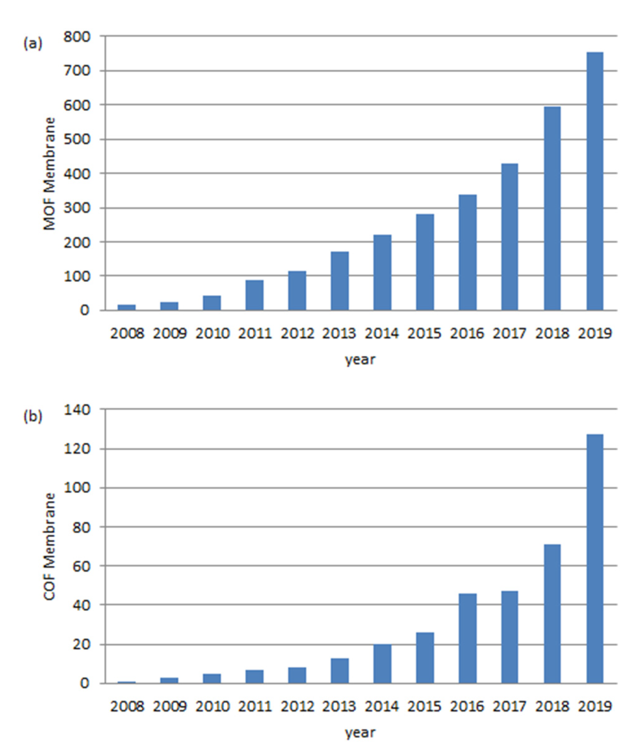
Figure 1. Number of publications per year (a) “Metal Organic Framework membranes” and (b) “Covalent Organic Framework membranes”. Data obtained from the Web of Science.
Membranes 10 00107 g001
Figure 2. Schematic illustration of the preparation procedure for the free-standing HKUST-1 membrane. Reprinted with permission from [45], Copyright (2012) John Wiley and Sons publications.
Membranes 10 00107 g002
Figure 3. Schematic illustration of the preparation of a pure ZIF-67 membrane by self-conversion of carbonate hydroxide nanowire arrays (Co-NWAs). Reprinted with permission from [53], The Royal Society of Chemistry, Copyright (2018).
Membranes 10 00107 g003
Figure 4. (a) Schematic diagram of UiO-66-NH2(Zr/Hf) membrane preparation procedure. SEM images of the (b) α-Al2O3 support, (c) seed layer, and (d) UiO-66-NH2(Zr) membrane surface. (e) XRD patterns of UiO-66-NH2(Zr/Hf) membrane. (f) FTIR spectra of UiO-66-NH2(Zr/Hf) membrane. Reprinted with permission from [63], Copyright (2019) Elsevier.
Membranes 10 00107 g004
Figure 5. (a) Representative digital photograph of a gas separation module (CuBTC growth on the outer surface of the PBI-BuI hollow fibres (CuBTC@PBI-BuI-Out) is seen through the cut); (b) schematic for the interfacial synthesis approach of CuBTC@PBI-BuI-In and -Out; and (c) microscopic images of the ZIF-8@PBI-BuI-In, ZIF-8@PBI-BuI-Out, CuBTC@PBI-BuI-In, and CuBTC@PBI-BuI-Out composites synthesised. Reprinted with permission from [71], The Royal Society of Chemistry, Copyright (2015).
Membranes 10 00107 g005
Figure 6. GVD fabrication of an ultrathin ZIF-8 membrane. (a) Schematic of the MOF membrane formation process. (b) Schematic illustration and chemical structure of Zn-based gel and crystalline structure of ZIF-8. Zn, O, C, and N atoms are depicted in yellow, red, grey, and blue, respectively. H atoms are not presented for clarity. Top view SEM images of (c) the PVDF hollow fibre and (d) the Zn-based gel layer. SEM images of (e) top and (f) cross-sectional view of the ZIF-8 membrane prepared with sol concentration of 1 U and coating time of 2 s. The images are coloured for clarity. Scale bar, 200 nm. Reprinted with permission from [72], Copyright (2017) Springer Nature.
Membranes 10 00107 g006
Figure 7. (a) Photographs of an untreated Al2O3 tube and a tubular COF-LZU1 membrane. (b,c) Top-view SEM images of an untreated Al2O3 tube (b) and a tubular COF-LZU1 membrane (c). (d,e) Cross- sectional SEM images of an untreated Al2O3 tube (d) and a tubular COF-LZU1 membrane (e). (f) EDXS (Energy-dispersive X-ray spectroscopy) mapping of the cross-section of a tubular COF-LZU1 membrane and corresponding elemental distributions. C is the tracer for the COF layer, and Al is the tracer for the ceramic tube. Reprinted with permission from [78], Copyright (2018) John Wiley and Sons publications.
Membranes 10 00107 g007
Figure 8. (a,b) Photographs of M-TpBD and M-TpTD demonstrating the membrane flexibility. (c,f) SEM images showing surface of M-TpBD and M-TpTD COMs, which also infer that the membrane surface is free from defects and cracks; (d,g) is the cross-section; (e,h) is the corresponding zoomed view of M-TpBD and M-TpTD respectively; (i,j) AFM images of M-TpBD and M-TpTD respectively showing the surface roughness recorded on the top of a silicon wafer (scale bars: (c,f) 5 μm; (d,g) 50 μm, and (e,h) zoomed view 10 μm). Reprinted with permission from [79], Copyright (2016) John Wiley and Sons publications.
Membranes 10 00107 g008
Figure 9. Top view SEM image of (a) the 100 nm membrane, and cross-sectional SEM images of the membranes with different thickness 100 nm (b), 210 nm (c), and 290 nm (d). The inset in (a) is the corresponding nitrogen EDS mapping, and the inserts in (bd) are corresponding schematic representations of different numbers of restacked layers. Reprinted with permission from [82], The Royal Society of Chemistry, Copyright (2016).
Membranes 10 00107 g009
Figure 10. Strategy for the fabrication of the [COF-300]-[UiO-66] composite membrane. Zirconium, carbon, nitrogen, and oxygen atoms are shown as cyan, grey, blue, and red, respectively. Hydrogen atoms are omitted for clarity. Reprinted with permission from [94], The Royal Society of Chemistry, Copyright (2018).
Membranes 10 00107 g010
Figure 11. Schematic illustration for the preparation of Tb-AIP mixed matrix membranes (MMMs). Reprinted with permission from [100], Copyright (2017) Elsevier.
Membranes 10 00107 g011
Figure 12. Schematic illustration for the fabrication of mixed-matrix ultrafiltration membrane, molecular structures of the polymer matrix (polyacrylonitrile) and the 2D nanofiller (COF). Reprinted with permission from [99], Copyright (2019) Elsevier.
Membranes 10 00107 g012
Figure 13. Illustration of fabrication for ZIF-8/XLPEO MMMs: (a) ZIF-8 framework synthesised from zinc ion and 2-methylimidazole, (b) highly adjustable gas-permeability of XLPEO matrices derived PEGDA and PEGMEA pre-polymers with various molar ratios. (c) Formation process of ZIF-8/XLPEO MMMs through the one-step UV polymerisation and (d) schematic illustration for interfacial interaction between ZIF-8 fillers and XLPEO matrices in the resulting MMMs. Reprinted with permission from [101], Copyright (2019) Elsevier.
Membranes 10 00107 g013
Figure 14. Ideal and nonideal MOF MMM architectures. Reprinted with permission from [118], Copyright (2019) American Chemical Society.
Membranes 10 00107 g014
Figure 15. SEM images of (a) ACOF-1 and (b) the cross-section of a 16 wt % ACOF-1@ Matrimid® MMMs. TEM images (c) and particle-size distribution (d) of ACOF-1. (e) Raman spectra of the pure components and MMMs. (f) Spectroscopic fraction of COF calculated at random positions of two different MMMs (8 and 16 wt % COF loading). Reprinted with permission from [127], Copyright (2016) John Wiley and Sons publications.
Membranes 10 00107 g015
Figure 16. (A) Synthetic procedures of UiO-66-NH2@PI. (B) The TEM image of UiO-66-NH2@PI, scale bar 50 nm. (C) FT-IR spectra of UiO-66- NH2, polymers, and modified UiO-66-NH2 and (D) the MALDI-TOF spectrum of the digested UiO-66-NH2@PI. The peaks highlighted in green correspond to the given polymer structure. (E) The photo of a stand-alone single component UiO-66-NH2@PI membrane with 88 wt % MOF loading, scale bar 5 mm. Reprinted with permission from [140], Copyright (2018) American Chemical Society.
Membranes 10 00107 g016
Figure 17. (a) Photograph of free-standing 50 wt % MOF-loaded UiO-66-allyl-C MMM. (be) SEM images (top side) of MMMs: (b) PDMS-only membrane, (c) UiO-66-allyl MMM, (d) UiO-66-allyl + PDMS MMM, and (e) UiO-66-allyl-C MMM. All MOF-containing MMMs are at 50 wt %. Scale bars are 2 μm. Reprinted with permission from [118], Copyright (2019) American Chemical Society.
Membranes 10 00107 g017
Figure 18. (A) Schematic representations of the synthesis of COFs and their packing models indicating the pore aperture and stacking distances. (B) Overview of the solution-casting method for COF@PBI-BuI hybrid membrane fabrication. (C) Digital photographs showing the flexibility of TpPa-1 and TpBD(50)@PBI-BuI hybrid membranes. Reprinted with permission from [141], Copyright (2016) John Wiley and Sons publications.
Membranes 10 00107 g018
Figure 19. Schematic of COFp-PVAm membranes. Oversized COFp are penetrated by PVAm to create appropriately sized CO2-selective channels. d: kinetic diameter. Reprinted with permission from [142], Copyright (2019) American Chemical Society.
Membranes 10 00107 g019
Figure 20. (a) CO2/CH4 separation performance of the mixed-linker ZIF-7x-8 membranes. The ZIF-722-8 membrane shows the highest CO2/CH4 separation factor of 25. (b) Comparison of CO2/CH4 separation performance of our ZIF-7x-8 membranes with other ZIF membranes. (c) Temperature swing stability of the ZIF-722-8 membrane for CO2/CH4 separation. Reprinted with permission from [205], Copyright (2019) John Wiley and Sons publications.
Membranes 10 00107 g020
Figure 21. Scanning electron microscopy images of the as-synthesised ZIF-8 membrane: (a) top view and (b) cross-sectional view. (c) Schematic representation of the rapid heat treatment (RHT) process. (dh) Gas separation properties of RHT ZIF-8 membranes: (d) gas separation characteristics of ZIF-8 at 30 °C as a function of rapid heat treatment parameters. (e) Ideal selectivity for various gas pairs at 30 °C as a function of the dwell time and temperature. (f) The calculated apparent activation energy for ZIF-8 membrane before and after RHT. Comparison of the CO2 separation performance of RHT ZIF-8 membranes with other reported MOF membranes: (g) CO2/CH4 and (h) CO2/N2, arrow shows the improvement in the separation performance after RHT. Reprinted with permission from [208], Copyright (2019) John Wiley and Sons publications.
Membranes 10 00107 g021
Figure 22. A graphic illustration of CO2 and N2 mixture gas across the UiO-66-CN@sPIM-1 membrane. (a) A summary of MOF-based hybrid membranes reported up to date for the application in CO2/N2 separation (b) a schematic illustration of CO2 and N2 transport across the UiO-66-CN@sPIM-1 membrane. Reprinted with permission from [222], Copyright (2019) John Wiley and Sons publications.
Membranes 10 00107 g022
Figure 23. (a) Illustration of the PEI grafting on the surface of COF-300 in COF@PEI. (b) FESEM and (c) TEM images of COF@PEI particles. Membrane cross-sectional FESEM images of (d) COF@PEI/6FDA-DAM-7 and (e) COF@PEI/Pebax-10 MMMs. (f) CO2/CH4 and (g) CO2/N2 separation performance of pure polymeric membranes and MMMs containing different fillers. Reprinted with permission from [226], The Royal Society of Chemistry, Copyright (2019).
Membranes 10 00107 g023
Figure 24. (a) Illustration of the hypothesis of gas separation through porous Zn2(Bim)3 nanosheets. Only Zn atoms are shown for clarity, and the light blue planes represent the nanosheets regardless of their amphiprotic natures. The solid and dashed lines represent the pathways of H2 (blue) and CO2 (red). (b) Binary gas separation performance of equimolar H2/CO2 through the Zn2(Bim)3 nanosheet membranes prepared at different temperatures via the hot-drop coating method. (c) Single gas permeation through a Zn2(Bim)3 nanosheet membrane prepared at 200 °C. (d) Effect of varying temperature on H2/CO2 permeance and mixture SF of a Zn2(Bim)3 nanosheet membrane prepared at 150 °C. Reprinted with permission from [230], Copyright (2017) John Wiley and Sons publications.
Membranes 10 00107 g024
Figure 25. Enhanced membrane stability, reduction in plasticisation, and high mixed-gas selectivity. (a), Quantification of membrane stability by Soxhlet extraction in refluxing dichloromethane. The fraction of membrane dissolved corresponds to the mass of membrane remaining after a given period of time in the extractor relative to the initial mass. (b) Illustration of the nanocrystal-induced polymer rigidification, along with the structures of M2(dobdc) and 6FDA-DAM. Mixed-gas permeation data for a 50:50 C2H4/C2H6 (c) and a 50:50 CO2/CH4 mixture (d). Error bars correspond to propagation of uncertainty from the mass spectrometer calibration. (e), Single-component C2H4 permeabilities, normalised to the permeability measured at 0.75 bar. Uncertainty in permeability corresponds to propagation of error from uncertainty in the film thickness, area and feed pressure. All permeabilities were collected at 35 °C, and steady-state permeation values were taken after six-time lags. The composition was sampled from permeate that accumulated after steady-state permeation was reached. Permeability and selectivity data correspond to neat 6FDA-DAM (black squares) and 25% Ni2(dobdc)/6FDA-DAM (purple circles). Reprinted with permission from [247], Copyright (2016) Springer Nature.
Membranes 10 00107 g025
Figure 26. (a) Water permeance and rejection rates of the tubular COF-LZU1 membrane in the nanofiltration of different dyes (photographs show the colours of the dye solutions before (1) and after (2) NF). (b) Stability test of the tubular COF-LZU1 membrane in a long-time NF of chrome black. Operating pressure: 0.5 MPa; dye concentration: 100 mgL−1; room temperature. Reprinted with permission from [78], Copyright (2018) John Wiley and Sons publications.
Membranes 10 00107 g026
Figure 27. (a) Molecular-weight cut-off (MWCO) curve showing that the M-TpBD and M-TpTD had 90% rejection of PEG at 915 Da and 1100 Da, respectively, confirming the pores are in the nanofiltration range; (b,c) pure solvent permeance versus molecular diameter of different protic (water, methanol, ethanol, 2-propanol, and n-butanol) and aprotic (acetonitrile, acetone, 2-butanone, and N,N′-dimethylacetamide) solvents; (d) water and acetonitrile permeance through COMs (M-TpBD and M-TpTD) over time (each 6 h intervals up to 30 h); (e) nanofiltration performance of M-TpBD and M-TpTD using different molecules (vitamin B12 (V-B12), rose Bengal (RB), Congo red (CR), curcumin (CM), methylene blue (MB), tetracycline (TC), and nitroaniline (NA)) as a marker in water and acetonitrile (only for CM). A nanofiltration experiment was conducted separately for each aforementioned molecule in a dead-end stirred cell (600 r.p.m.) at ambient conditions and 1 bar upstream pressure. Reprinted with permission from [79], Copyright (2016) John Wiley and Sons publications.
Membranes 10 00107 g027
Figure 28. (a) Cross-section SEM image of sample M20. (b) Permeances of water and a number of polar and nonpolar organic solvents through the three TFP-DHF 2D COF membranes with 15 (M15), 20 (M20), and 30 (M30) layers, plotted with the inverse of their viscosity. (c) Rejection rates of various dyes through the M20 membrane vs. their molecular weight. (d) Image showing the separation of the mixture dyes of Reactive Green (RG) and Primuline (P). The chamber on the left-hand side contains the mixture of the two dyes, whereas the chamber on the right-hand side is filled with fresh water initially and turned yellow after 1 day of diffusion. Reprinted with permission from [92], Copyright (2018) American Chemical Society.
Membranes 10 00107 g028
Figure 29. (a) Arrhenius plots of the membranes. (b) Polarisation curves and power densities of the semi-passive direct methanol fuel cells (DMFCs) using the membranes in 1.0 m methanol at 80 °C. (c) The illustration of the proton transportation mechanism through the DNA@ZIF-8 membrane. Reprinted with permission from [281], Copyright (2018) John Wiley and Sons publications.
Membranes 10 00107 g029
Table 1. Summary of MOF and COF membrane preparation methods.
Preparation MethodThicknessAdvantagesLimitationsApplicationsReferences
MOFIn situ or direct growth300 nm–100 µmSimple and universal
Tunable thickness
Functional substrate surface required
Poor heterogeneous nucleation site on the support
Gas separation[45,46,47,48,49,50,51,52,53]
Pervaporation
OSN
Seeded assisted or secondary growth1–25 µmBetter control of nucleation and crystallinity Various types of supportsComplex procedure
Fix small nanosize MOF seeds to the support surface Thicker thickness
Gas separation
Water treatment Pervaporation
[54,55,56,57,58,59,60,61,62,63]
Layer-by-layer assembly500 nm–2 µm/up to 10 µmControllable thicknessRough surfaceGas separation[64,65,66,67,68]
Ultra-thin layerSmall-scale
Contra-diffusion or interfacial method2–25 µmVarious types of supports Gas separation[69,70,71]
Fit for fast reaction Pervaporation
Controllable thickness OSN
Vapour deposition10–150 nmEnvironmentally friendly
Time-saving
Controllable thickness/Ultra-thin layer
Small-scaleGas separation[72,73,74,75]
COFIn situ growth400 nm–4 µmSimple Tunable thicknessFunctional substrate surface required Gas storage and separation[76,77,78]
(support the initial growth of COFs on the surface)Water treatment
Solution casting100–700 nmSimple and scalableThicker thickness
Less controllable
Water treatment[79,80]
OSN
Fuel cell (PEM)
Layer-by-layer assembly100–500 nmControllable thicknessExtra steps (exfoliation)Gas separation[81,82,83]
Ultra-thin layer
Interfacial polymerisation (IP) 2–300 nm / up to 100 µmDirectly forming and scalable
Tunable thinkness
Water treatment[87,88,89,90,91]
OSN
Langmuir−Blodgett (LB) method3–100 nmFew COF layers of depostion feasibleSmall-scaleWater treatment[92]
Can be tranformed to different substrats
Turnable thinkness