Article

CO2 Transcritical Refrigeration Cycle with Dedicated Subcooling: Mechanical Compression vs. Absorption Chiller

by
Evangelos Bellos
* and
Christos Tzivanidis
Thermal Department, School of Mechanical Engineering, National Technical University of Athens, Zografou, Heroon Polytechniou 9, 15780 Athens, Greece
*
Author to whom correspondence should be addressed.
Appl. Sci. 2019, 9(8), 1605; https://doi.org/10.3390/app9081605
Submission received: 21 February 2019 / Revised: 28 March 2019 / Accepted: 12 April 2019 / Published: 18 April 2019
(This article belongs to the Special Issue Solar Cooling Systems)

Abstract

:
The objective of this paper is the comparison of two dedicated subcooling methods, after the gas cooler, in a CO2 transcritical refrigeration system. The use of vapor compression refrigeration with R134a for subcooling is the first method, and the second is the use of an absorption chiller that operates with a LiBr-H2O working pair. The examined systems are compared energetically and exegetically with the reference transcritical CO2 refrigeration cycle without subcooling. The analysis is conducted for different operating scenarios and in every case, the system is optimized by selecting the proper temperature and pressure levels. The analysis is performed with a developed and validated model in Engineering Equation Solver. According to the final results, the use of the absorption chiller is able to decrease the system electricity consumption by about 54% compared to the simple transcritical cycle, while the decrease with the mechanical subcooling is 41%. Both systems with dedicated subcooling are found to have an important increase in the system exergy performance compared to the simple transcritical cycle. However, the system with the mechanical subcooling is found to be the best choice exegetically, with a small difference from the system with the absorption chiller.

1. Introduction

Refrigeration is responsible for a great part of the worldwide energy consumption [1], as well as for global warming because of the use of harmful refrigerants [2]. In recent years, regulations such as the EU F-Gas Regulation 517/2014 [3] have been created in order to establish the use of clean and sustainable refrigerants, such as CO2, NH3, propane, butane, and, generally, refrigerants with lower Global Warming Potential (GWP) values [4]. However, there is not a global optimum refrigerant from all the points of view (performance, environmental impact, and safety level) [4,5]. CO2 is the unique refrigerant which is non-toxic, non-flammable (A1 ASHRAE safety group), and has an extremely low global warming potential (GWP = 1), but its refrigeration systems suffer from reduced efficiency [6].
So, a lot of research has been focused on the refrigeration systems with CO2 as the main or the only refrigerant [7], in order to design systems with higher performance. One important reason for the lower performance of the CO2 refrigeration systems is the relatively low critical temperature of CO2, which is 31.1 °C. So, the CO2 refrigeration systems cannot operate with latent heat rejection to the ambient, especially in warm climates conditions, and they operate in transcritical mode [8]. This fact is the key parameter that leads to a decreased coefficient of performance (COP) and, consequently, to higher electricity consumption. In this direction, a lot of researchers have studied the use of alternative methods for enhancing the COP of the refrigeration cycle with CO2 [9].
The use of an internal heat exchanger, after the condenser and after the evaporator, is a simple way for subcooling the CO2 refrigerant. Chen et al. [10] studied this idea and they determined the optimum system high pressure with the heat exchanger. Moreover, Torrella et al. [11] found a 12% enhancement with the use of an internal heat exchanger for subcooling purposes. The next studied idea regards the use of a two-stage compression system. Cavallini et al. [12] found that this idea increases the system coefficient of performance (COP) about 25%. In this direction, the use of a parallel compressor has been studied by Sarkar et al. [13] and they found maximum possible enhancement, up to 47%, when there is a high-temperature difference between the heat rejection and the refrigeration temperature levels. The parallel compression has been found to increase the COP about 19%, according to Gullo et al. [14], while Chesi et al. [15] found 30% improvement experimentally.
The incorporation of ejector devices in the system for increasing the COP of the refrigeration cycles has been also studied in the literature. Nakaqawa et al. [16] found that the COP can be improved up to 26% with the use of an ejector, while Chen et al. [17] found enhancements in the ranges of 25% to 30%. An alternative idea regards the use of an expander in the system in order to produce a small work amount and to decrease the network demand. Yang et al. [18] found that this idea is able to increase the COP of a CO2 refrigeration system up to 11%, while similar enhancements, about up to 12%, have been found by Megdouli et al. [19]. The utilization of cascade refrigeration systems with CO2 is also common in the literature. Sanchez et al. [20] studied an R134a/CO2 cascade refrigeration system and they stated that the direct cascade system is more efficient than the indirect system with a deviation of about 11%. Megdouli et al. [21] examined a cascade system with CO2/N2O and ejectors, and they concluded that these refrigerants have similar performances in the cascade systems because of their similar critical temperatures. Moreover, the use of NH3/CO2 cascade systems is common in the literature [22].
The previous ways for enhancing the performance of a CO2 refrigeration system are effective and interesting. However, in a recent review paper, Llopis et al. [23] highlighted that the dedicated subcooling is a more effective method among the previously discussed. More specifically, they stated that the dedicated subcooling increases, by 30%, the COP, which is a higher value compared to the other reviewed techniques, under the same operating conditions. They stated that the dedicated subcooling can be performed using three different technologies: (a) mechanical compression cycle, (b) absorption chiller, and (c) thermoelectric system. At this point, it has to be said that the dedicated subcooling is performed with an external refrigeration cycle, which can be driven by renewable energy sources, such as solar energy. For example, there is the possibility to use photovoltaic panels in order to drive the dedicated mechanical subcooling or solar thermal collectors (e.g., flat plate collector or evacuated tubes) for driving the dedicated subcooling with an absorption chiller.
The most common dedicated subcooling is the use of an external mechanical compression subcooling system (M-SC) which consumes extra electricity. The basic idea is that the increase of the cooling capacity, due to the subcooling, and the simultaneous decrease of the optimum high-pressure lead to a high reduction in the electricity consumption of the primary compressor, which overcomes the extra electricity consumption in the secondary cycle. Llopis et al. [24] studied this configuration with various refrigerants, included R134a in the secondary refrigeration cycle, and they found 20% higher COP and 29% higher cooling capacity. Furthermore, Llopis et al. [25] stated that the COP enhancement can reach up to 30% when the heat rejection temperatures are high. Moreover, Gullo et al. [6] studied the use of R134a in the secondary loop and they found the total equivalent warming impact to be 10% lower compared to the booster system in Athens (Greece) and 25% for Valencia (Spain). Nebot-Andres et al. [26] compared the use of a cascade system with a mechanical subcooling system with R1234yf in the secondary cycle, and they concluded that both systems increase the COP but the mechanical subcooling system gives the best results. Dai et al. [27] studied the use of zeotropic mixtures in the secondary cycle in order to reduce the temperature difference during the heat transfer from the one cycle to the other. According to their results, the COP is found to be 35% with the subcooling and the optimum subcooling temperature difference can be up to 38 °C.
The next part of the literature includes methods of dedicated subcooling by the utilization of a heat source. In these cases, the electricity consumption of the system is reduced and extra heat input is needed. The use of renewable or alternative energy sources, such as solar energy, geothermal energy, and waste heat, can be effective choices for reducing the environmental impact of the refrigeration system. Salajeghe and Ameri [28] studied the use of an absorption chiller operating with LiBr-H2O for subcooling the CO2 after the gas cooler (ACH-SC). The absorption chiller was powered by a solid oxide fuel cell and they studied the system with and without subcooling, as well as with and without an internal heat exchanger. They found that the use of an absorption chiller for subcooling is a more effective technique than the internal heat exchanger, while they stated that the global optimum system combines both an absorption chiller and internal heat exchanger for subcooling. Mohammadi [29] investigated various configurations of the CO2 refrigeration system with single or two-stage cycles and with the use of different absorption machines for subcooling. They utilized the heat of the compressor outlet in order to feed the absorption machines. They finally concluded that the combination of a two-stage compression cycle with intercooler and dedicated subcooling from the absorption chiller is a very effective way of enhancing the COP, up to 207%.
At this point, it is also important to state that the use of an absorption (or adsorption) chiller in a cascade system with CO2 cycles has been also examined in the literature with encouraging results. More specifically, Mohammadi and McGowan [30] found that the incorporation of an absorption chiller in the high-stage stage of a cascade configuration is able to reduce the operation cost about 36% to 49% on a yearly basis. Moreover, Cylkis [31] found a 30% decrease in electricity consumption with the use of a sorption chiller coupled to a compression system. Furthermore, the combination of CO2 cycles with absorption machines for power and refrigeration production has been also studied in the literature. Li et al. [32] studied the use of an absorption chiller coupled to a gas turbine, while Arora et al. [33] studied a CO2-Rankine cycle with an absorption chiller for power and refrigeration production.
The use of a thermoelectrical subcooler has been studied by various researchers. Sarkar [34] found a 25% increase in the COP with the thermoelectrical device compared to the simple vapor compression cycle. Schoenfield et al. [35] found a 3.3% COP enhancement and 7.9% cooling capacity increase with the thermoelectrical subcooling device. Jamali et al. [36] found 19% COP improvement with a thermoelectric device that consumes electricity. In the end, Dai et al. [37] examined different configurations with a thermoelectrical subcooling device and expander, and they concluded that the combination of these two techniques increases the COP around 38%. Lastly, the work of Aprea et al. [38] should be highlighted, whereby they studied the use of a desiccant dehumidification system with air in order to enhance the performance of a transcritical CO2 cycle. They found 77% enhancement in the COP compared to the conventional system with this technique.
The previous literature review makes clear that the investigation of CO2-modified refrigeration cycles is of high interest and presents important enhancements in the COP that can be achieved in order to reduce the work consumption. The enhancement of the COP in the transcritical CO2 refrigeration cycle is a critical issue because this cycle is less effective than the respective subcritical cycle with conventional refrigerants, such as R134a [39]. Dedicated subcooling techniques are important choices for increasing the performance of the system in a great way. Especially in the cases that solar energy is applied for driving the subcooling cycle, the overall configuration becomes environmentally friendly. There is plenty of studies about these techniques, but the studies about dedicated subcooling with absorption chillers are restricted. Only the studies [28,29] are found in this area, but they do not make any comparison with the other usual technique: the mechanical subcooling. At this point, it has to be said that there are existing studies with vapor compression cycles and absorption chillers in a cascade configuration, but these configurations are different from the use of an absorption chiller as the subcooling device. In this direction, this study aims to cover this scientific gap and to compare the reference CO2 refrigeration cycle, with dedicated subcooling system, with the mechanical compression cycle and the absorption chiller (single stage with a LiBr-H2O working pair) separately. To our knowledge, there is no other study which compares these two dedicated subcooling techniques and so this work is novel. The difference of this work compared to references [28,29] is based on the investigation of both the two subcooling techniques and not only the absorption chiller subcooling method, which is a factor that is important in order to make a suitable comparison under the same operating conditions. Moreover, the comparison of these techniques is very important because the mechanical subcooling consumes work and electricity, while the absorption chiller subcooling consumes heat, so there is a need for a deep and detailed comparison. The analysis is conducted for different operating scenarios (refrigeration temperature and heat rejection temperature). In every case, the temperature and the pressure levels of every system are optimized in order to perform a suitable comparison. The analysis is conducted with developed models in Engineering Equation Solver (EES) [40] and these models are validated with literature results. The analysis is performed using energetic and exegetic criteria in order to evaluate, properly, the simultaneous use of work and heat input in the system with the absorption chiller.

2. Material and Methods

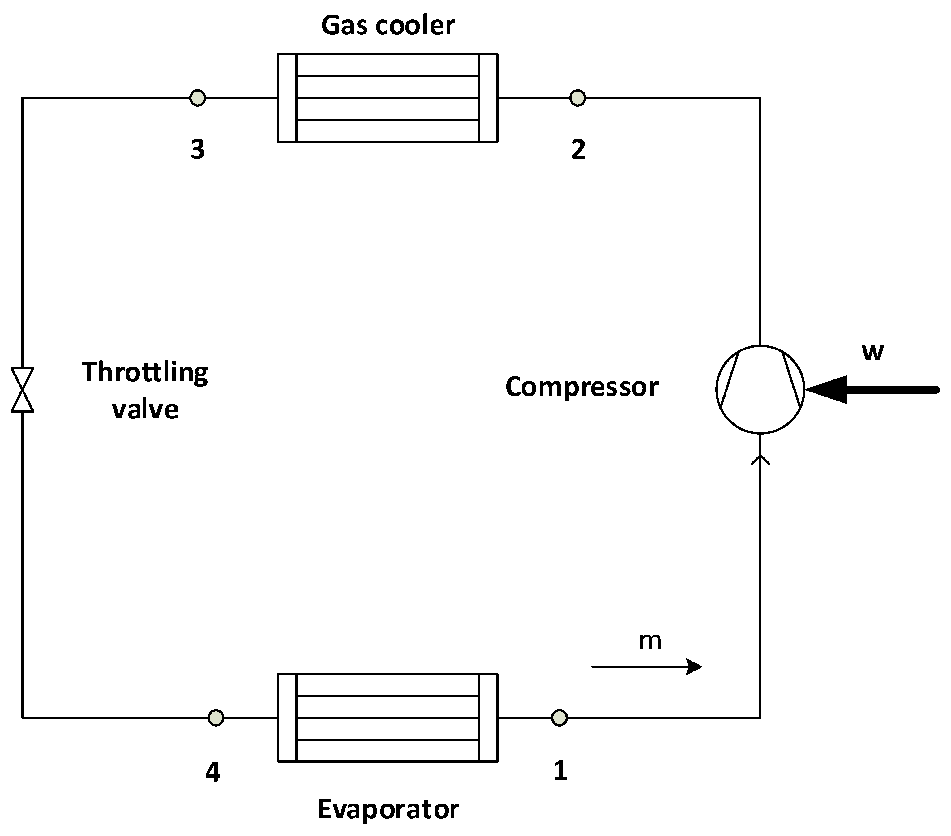
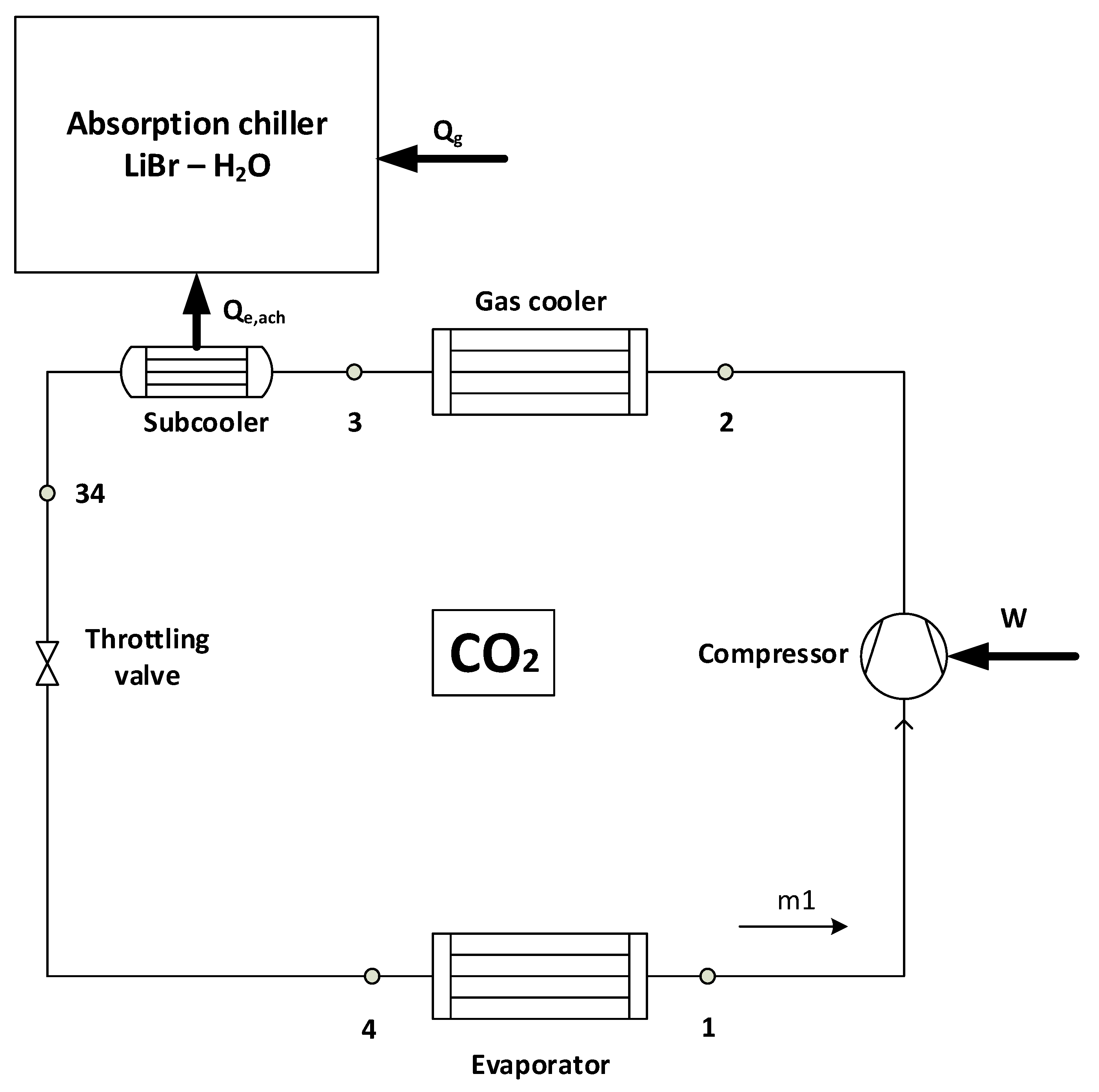
2.1. The Examined Systems

The first examined system was a simple vapor compression cycle, which is depicted in Figure 1, and it was assumed to be the reference system (Ref). The working fluid was CO2 (R744) and it operates in transcritical mode. The gas cooler outlet temperature (T3) was called, in this work, the heat rejection temperature level and it also can be symbolized as (Tc). This system produces 100 kW of cooling and consumes work (W) in the compressor.
The next examined system was the one with mechanical dedicated subcooling (M-SC), which produces 100 kW of refrigeration. This system uses CO2 in the main cycle and R134a in the secondary cycle. This refrigerant was selected as a usual selection in the literature [24,25]. In this system, there is the possibility to use photovoltaic panels, for example, in order to drive the secondary refrigeration cycle and to create an overall environmentally-friendly system. Figure 2 illustrates this system and it has to be said that the condenser of the secondary system was assumed to operate at the same temperature level as the gas cooler outlet temperature. In other words, the temperature (T3) was assumed to be the same as the (T33), which is saturated liquid. This system consumes work in the primary cycle (W) and in the secondary cycle for the subcooling (Wsc). The temperature of the evaporator in the secondary system (T11) was assumed to be 5 °C lower than the temperature level (T34). Moreover, it has to be said that there was no superheating in the secondary cycle evaporator (or subcooler device).
The last examined system is depicted in Figure 3, and it is the system with dedicated subcooling with the absorption chiller, which produces 100 kW of refrigeration. The detailed description of the absorption chiller is given in Appendix A. In this system, there is the possibility to use solar thermal collectors in order to drive the absorption chiller and to create an overall environmentally-friendly system. The absorption chiller is a single stage machine with an internal heat exchanger (70% effectiveness), which operates with the LiBr-H2O working pair. This machine was assumed to reject heat at the ambient (from the condenser and the absorber) at the temperature level (Tc), which is the same as the gas outlet temperature in every case. The absorption chiller evaporator temperature (Te,ach) was assumed to be 5 °C lower than the (T34). Moreover, the minimum values of the (Te,ach) were assumed to be 5 °C, because the refrigerant is water in the absorption chiller and it cannot operate at a lower temperature level due to the danger of freezing. This system operates by using a heat input in the generator (Qg) and it does not consume work.
The last step in this section is the presentation of the pressure-specific enthalpy (p-h) diagrams for the cycles in Figure 4. Figure 4a shows the p-h diagram for the reference cycle, while Figure 4b shows the same for the other cases with dedicated subcooling. It was obvious that the cooling capacity is higher in the cases with the subcooling because the distance between the state points (4) and (1) was greater in Figure 4b compared to the respective in Figure 4a.

2.2. Mathematical Formulation

In this section, the basic equations about the mathematical modeling of the systems are presented. Firstly, the detailed modeling of the CO2 cycle is given. The modeling and the description of the absorption chiller are given both in Appendix A.
The refrigeration production (Qe) in the evaporator of the main cycle is calculated as:
Q e = m ( h 1 h 4 )
The work input in the CO2-compressor (W) is given as:
W = m ( h 2 h 1 )
The compressor isentropic efficiency (ηis) is defined as below:
η is = h 2 is h 1   h 2 h 1  
In this work, the isentropic efficiency is calculated using the pressure ratio (r) according to the next formula [41]:
η is = 0.9343 0.04478 r
where the compression pressure ratio (r) is defined as:
r = p high p low
The process in the throttling valve is assumed to be adiabatic and so the enthalpy is the same between the inlet and the outlet:
h 3 = h 4
The reference system COP is defined a below:
COP = Q e W
The COP of the system with mechanical subcooling is given as:
COP = Q e W + W sc
The COP of the system with absorption chiller subcooling is given as:
COP = Q e W + Q g
At this point, it has to be said that the secondary refrigeration cycle with R134a is modeled as the CO2. The modeling of the absorption chiller is not given in detail here, but it follows the modeling of [42,43,44].
An extra equation that has to be written is associated with the heat transfer in the subcooler. The evaporation temperatures of the R134a cycle (Te,m), as well as of the absorption chiller (Te,ach), are selected to be 5 °C lower than (T34) [45]:
T 34 = T e , m + 5
T 34 = T e , ach + 5
In this work, except for the energy efficiency of the system (or COP), the exergy efficiency is used. This parameter is defined separately for every system as below:
Exergy efficiency (ηex) of the reference system:
η ex = Q e ( T 0 T e 1 ) W
Exergy efficiency (ηex) of the dedicated mechanical subcooling:
η ex = Q e ( T 0 T e 1 ) W + W sc
Exergy efficiency (ηex) of the dedicated absorption chiller subcooling:
η ex = Q e ( T 0 T e 1 ) W + Q g ( 1 T 0 T g )
The generator temperature (Tg) is the used temperature level for the determination of the exergy input in the absorption machine. The generator temperature is the saturation temperature of the strong solution at the high pressure inside the generator device (see Appendix A). All the temperature levels in the Equations (12)–(14) are in Kelvin units. Moreover, the reference temperature (T0) is selected at 298.15 K in this work.

2.3. Followed Methodology

In this work, the three systems were examined for different operating conditions. The refrigeration production was produced in four different temperatures (Te), from −35 °C up to 5 °C, with a step of 10 °C, while the heat rejection temperature (Tc) was studied from 35 °C up to 50 °C, with a step of 5 °C. Totally, 20 different operating scenarios were investigated in this work. In every case, the system was optimized properly in order to found the optimum design. The optimization criterion was the exergy efficiency in every case. For the reference system (Ref) and the system of mechanical subcooling (M-SC), the optimization with the exergy efficiency leads to the same results with the optimization with the COP as the optimization criterion. On the other hand, for the system with the absorption chiller, the optimization with the exergy efficiency did not give exactly the same results with the optimization based on maximum COP. However, the selection of the exergy efficiency as the optimization criterion was based on the greater suitability of this criterion in order to evaluate, properly, the temperature level of the generator temperature (Tg). The COP evaluates the (W) and the (Qg) as the same quantities, and the higher exergy potential of the work, compared to the heat source, was not taken into consideration. During the optimization procedure, the high-pressure level in the gas cooler was an important optimization variable. This variable was optimized by using the following equivalent optimization parameter. This parameter is called “pressure ratio” and it is the ratio of the maximum pressure (phigh) to the critical pressure of the CO2 (pcrit) which is 73.77 bar.
a = p high p crit  
For the system with subcooling, the evaporator temperature in the secondary cycle (Te,m) and in the absorption chiller (Te,ach) were also optimization variables. Moreover, the generator temperature was an extra optimization variable in the system with the absorption chiller. The optimization was conducted using the conjugate directions method or “Powell’s method”, which is included in the simulation tool EES [40]. The relative convergence tolerance was chosen at 10−8 and the maximum number of iterations (function calls) at 3000. Practically, this method is an iterative method, which assumes some initial values for the optimization variables and it tries to find the optimum values by using the gradient values of the objective function.
Moreover, it has to be said that some reasonable assumptions were made in this work. These assumptions are given below [25,27,46,47] and they regard the main cycle, as well as the subcooling cycles. Some of them have been given in the mathematical formulation of the paper, but they are listed also below in order to be all presented together.
-
There is no pressure drop in the devices.
-
All the systems are in steady-state conditions.
-
There is no superheating in the evaporator outlet for the main cycle, as well as for the subcooling cycles.
-
The expansion in the throttling valves is adiabatic, which means that the inlet enthalpy is equal to the outlet enthalpy because the process is adiabatic without any work production/consumption (first thermodynamic law). This assumption is applied in the main cycle, as well as in the subcooling cycles.
-
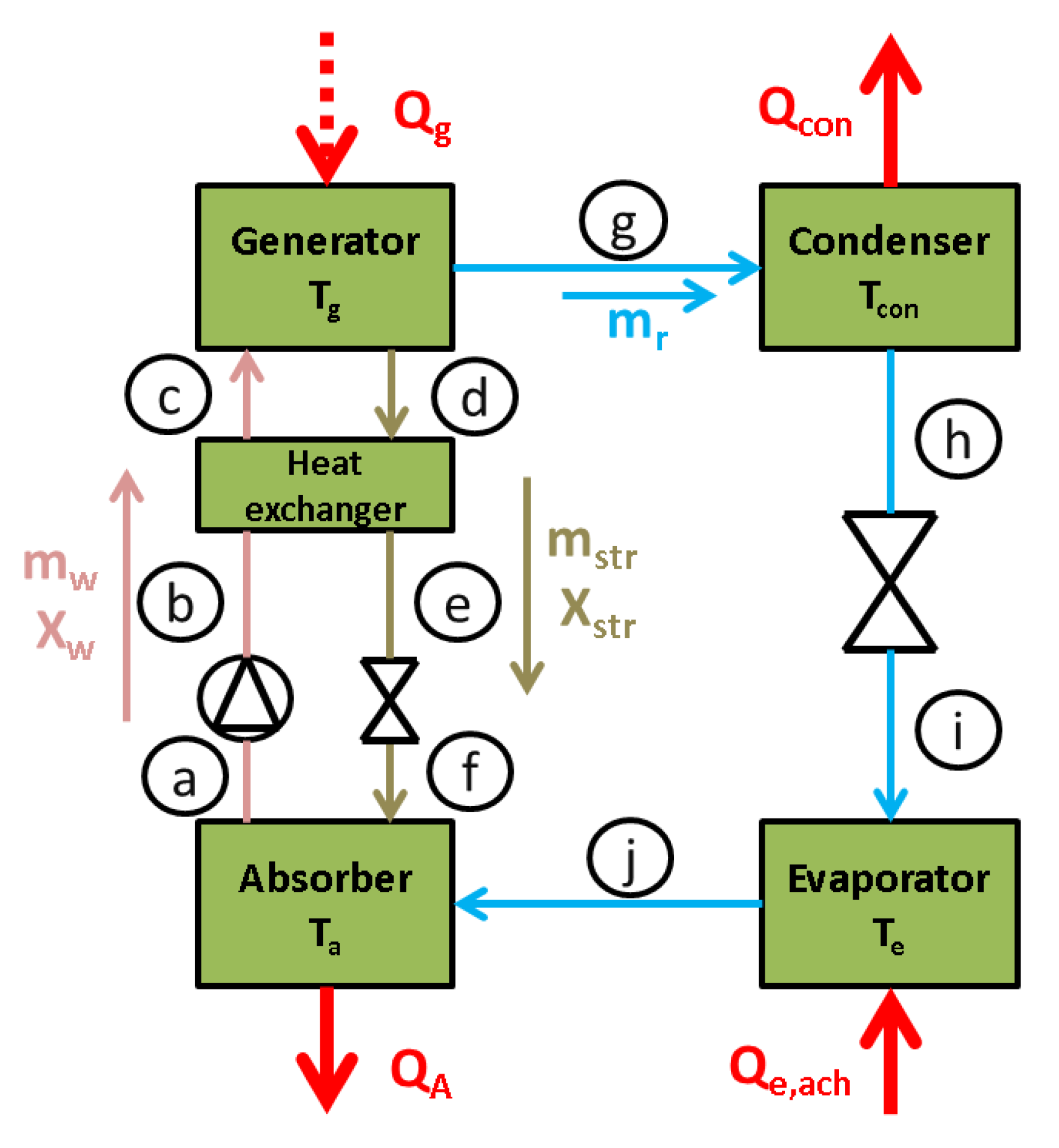
The heat exchanger effectiveness in the absorption chiller is 70%.
-
The cooling capacity is 100 kW in all the cases.
-
The heat rejection temperature is the same in all cases. More specifically this parameter (Tc) regards the gas cooler outlet temperature, the condenser of the M-SC, the condenser of the ACH-SC, and the absorber of the ACH-SC.
-
The approach temperature difference in the subcooler is 5 °C. This fact means that the evaporating temperature in the subcooling cycle is 5 °C lower than the temperature level of the CO2 in the outlet of the subcooler.
-
The cooling capacity of the subcooling system is depended on the operating conditions and on the subcooling value of every examined scenario.

2.4. Model Validation

The validation of the developed model for the reference system and the system with mechanical subcooling is performed using the experimental data of the reference [25]. Table 1 gives the validation results and it can be seen that the COP deviations between the literature and this work were 0.68% and 9.83%, respectively, with a mean value of 4.6%. The mean deviation was generally low (<5%) and so the developed model could be assumed to be accurate. The cases with subcooling (ΔΤsc) equal to zero corresponded to the reference case, while the others to the M-SC case. Lastly, it has to be said that suitable changes were performed in the developed program in order for this validation to be done. More specifically, the isentropic efficiency was properly modified according to [25], the refrigerant in the M-SC cycle was the R1234yf, and 5 °C of superheating after the evaporators was added.
In the end, it has to be said that validation evidence of the developed model and about the absorption chiller can be found in [42,43,44]. More specifically, the deviation in the COP between the developed model and the literature data was up to 2%.

3. Results and Discussion

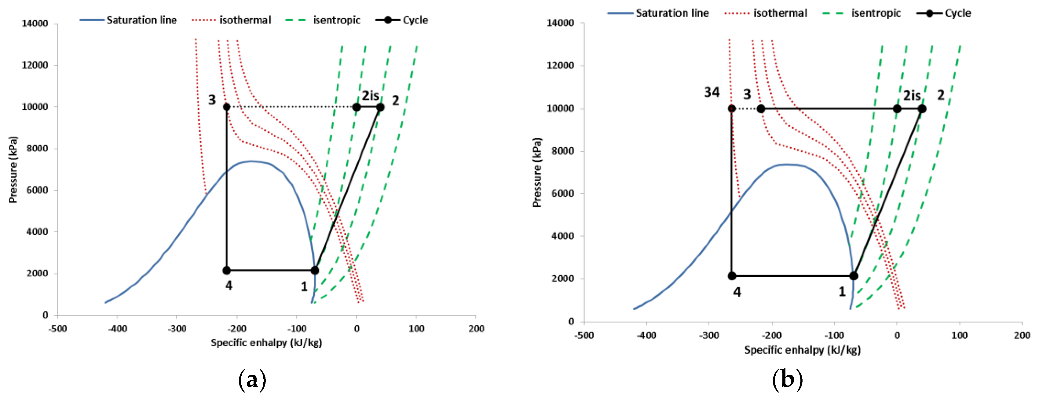
3.1. Reference System Performance

The reference was a simple vapor compression transcritical cycle with CO2 as the only working fluid. The system was examined for twenty different operating scenarios and the performance results are depicted in Figure 5. This figure illustrates the COP and the exergy efficiency of the examined cases and these results correspond to optimized operation. In this case, the optimization was conducted using only one optimization parameter, which was the pressure ratio parameter. Figure 5 shows that the COP increased with the increase of the evaporator temperature and with the decrease of the heat rejection temperature. On the other hand, the exergy efficiency was maximized for the evaporating temperature of −5 °C, while it had a decreasing rate with the increase of the heat rejection temperature. The reason for the maximum exergy efficiency for Te = −5 °C is based on two factors; the different behavior of the COP and of the exergy factor (T0/Te − 1) with the increase of the (Te) (higher (Te) leads to higher COP (see Figure 5)), but also to the lower exergy factor. The exergy efficiency is the product of these parameters, as it is given below using Equations (7) and (12):
η ex = COP ( T 0 T e 1 )
So, the existence of an intermediate optimum temperature level at −5 °C was a reasonable result because of the different behavior of the product factor with the (Te) increase. The maximum exergy efficiency was 27.12% and it was obtained for (Te = −5 °C and Tc = 35 °C), whereas for this case the COP was 2.424.
The previous results regard the optimum scenarios which have the optimum high pressure. Figure 6 and Figure 7 show the exergy efficiency for different pressure ratio parameters and for various cases. Figure 6 gives results for the evaporating temperature of −15 °C, while Figure 7 for the heat rejection temperature of 40 °C. It was obvious that, in all cases, there was an intermediate optimum pressure ratio parameter that leads to maximum exergy efficiency. It is remarkable to state that this optimum pressure ratio parameter leads also to maximum COP for the reference system because the exergy efficiency and the COP were proportional parameters for a constant (Te) according to Equation (15). Figure 6 indicates that the optimum pressure ratio parameter changed for different heat rejection temperatures, and higher heat rejection temperatures needed higher pressure levels after the compressor for optimum operation. On the other hand, the optimum pressure ratio parameter is not so affected by the refrigeration temperature, as Figure 7 proves. More specifically, all the optimum pressure ratios were about 1.35, which means that the maximum CO2 pressure was about 97 bar in these cases.

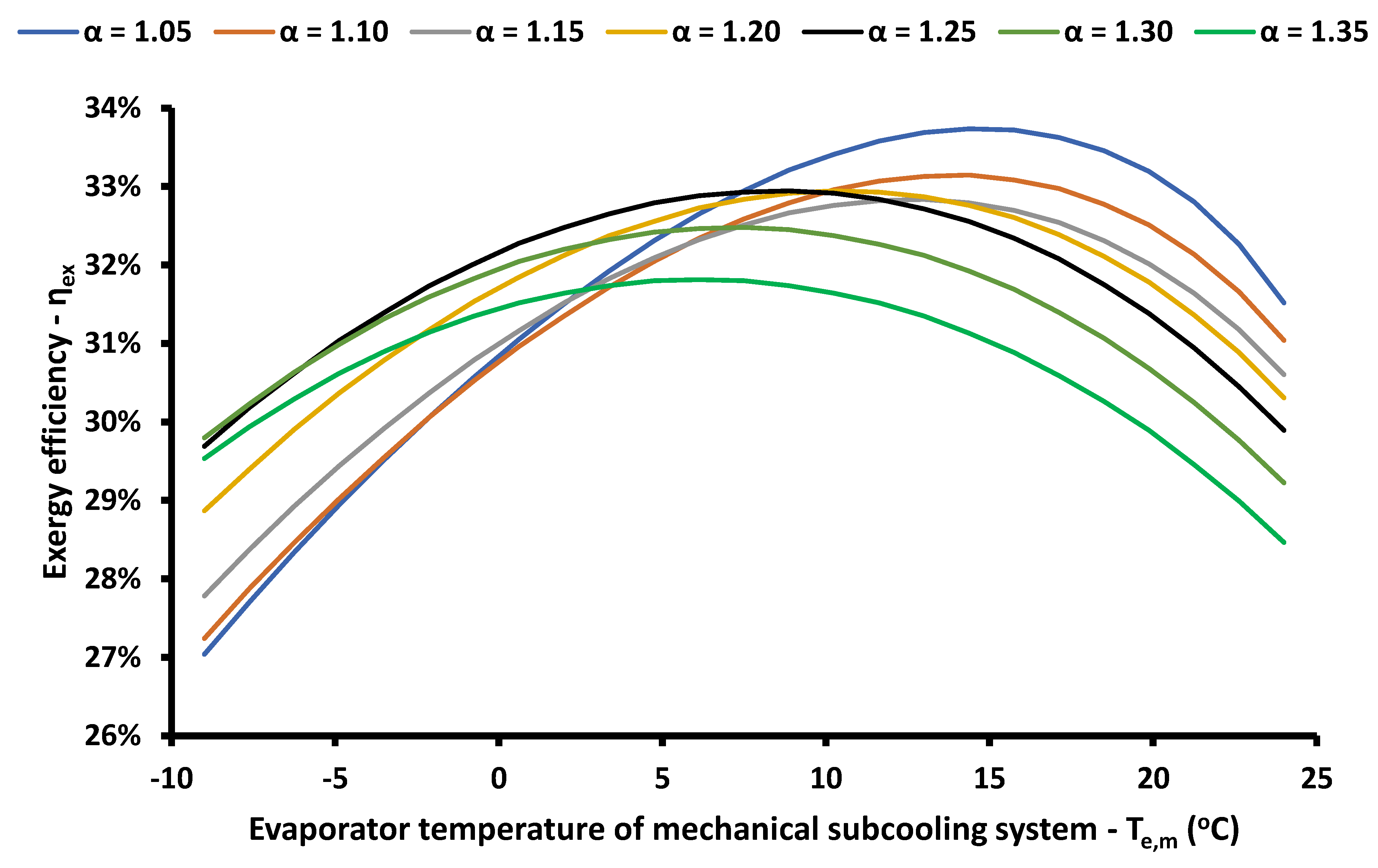
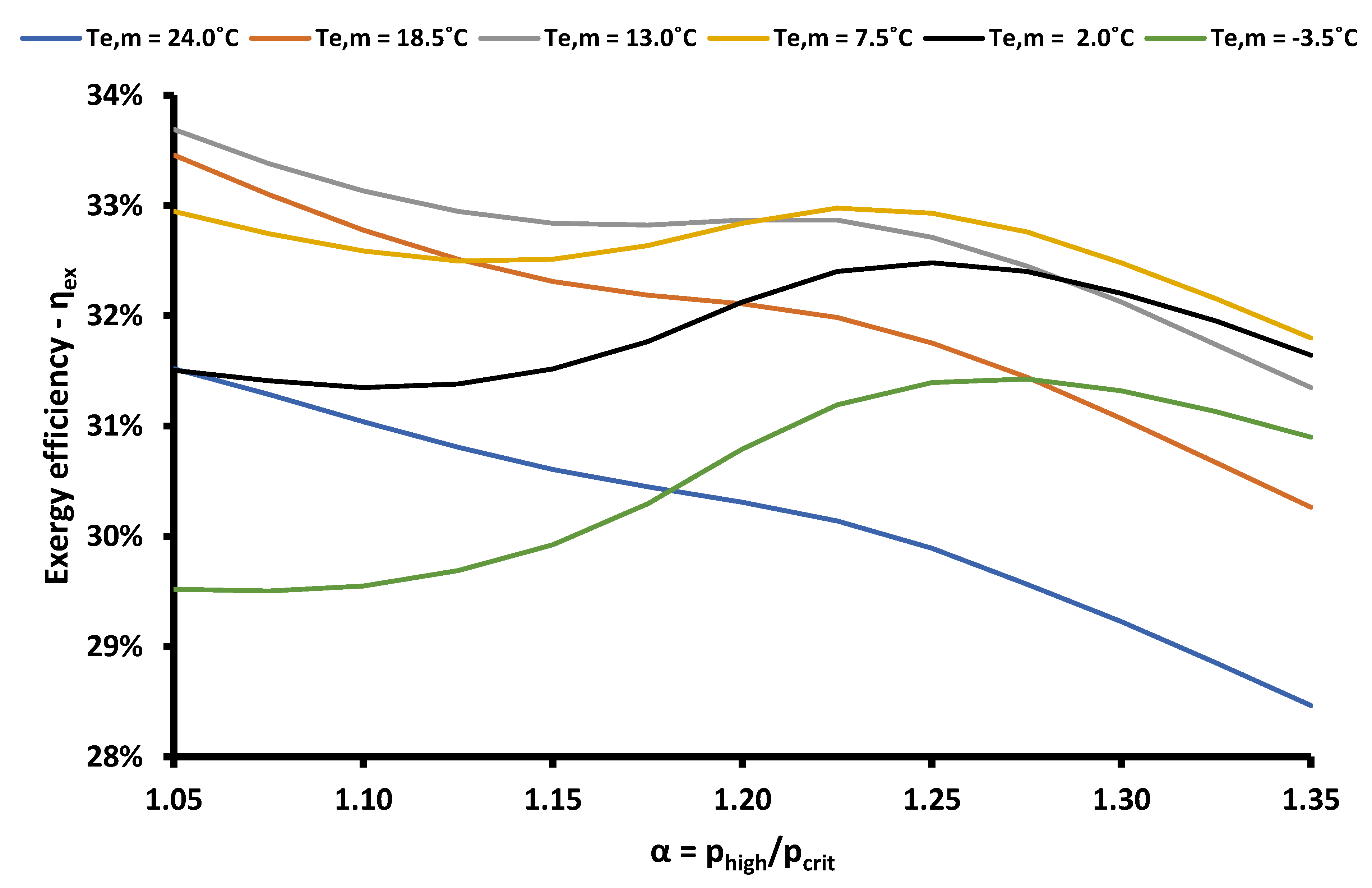
3.2. Mechanical Subcooling System Performance

The system with dedicated mechanical subcooling is investigated in this section. This system consumes extra work in the secondary refrigeration cycle which operates with R134a. The subcooling after the gas cooler gives two important advantages, the increase of the cooling capacity and the lower consumption in the CO2 compressor, because of the reduction in the optimum pressure compared to the conventional system. Figure 8 gives the COP of the M-SC system and of the Ref system, while the exergy efficiency of these systems is given in Figure 9. These cases are all optimized cases and so the comparison was able to be done. The curves of the M-SC system had similar trends compared to the Ref system, but they had higher values. In other words, the M-SC system presented increased COP and exergy efficiency; the facts that make it a promising choice for enhancing the performance of CO2 transcritical refrigeration systems. It is important to state that the overall maximum exergy efficiency was 38.46% and it was obtained for (Te = −15 °C and Tc = 35 °C), while for this case the COP was 2.482. Moreover, it has to be said that the optimum evaporating temperatures were equal to −15 °C for heat rejection temperatures up to 40 °C, while for higher heat rejection temperatures the optimum evaporating temperature was equal to −25 °C. It is remarkable to state that the optimum evaporating temperatures were lower in the M-SC system compared to the Ref system. This fact is based on the increased COP of the M-SC system, which makes the product of Equation (15) have different behaviors with the variation of the refrigeration temperature level.
The optimization of the M-SC system was performed using two parameters; the pressure ratio parameter (a) and the temperature level in the evaporator of the secondary cycle (Te,m). Figure 10 and Figure 11 exhibit the optimization procedure results for the case (Te = −15 °C and Tc = 40 °C). Figure 10 shows that the optimum values of the (Te,m) were generally in the region from 5 °C up to 15 °C, while the global optimum case was found for (a = 1.05 and Te,m = 14.38 °C). Figure 11 shows that the optimum pressure ratio parameters were for values close to (α = 1) when the (Te,m) was relatively high, and for values close to (α = 1.25) when the (Τe,m) had lower values. The reason for the different trends between the curves is based on the non-linear character of the CO2 saturation curve in the liquid phase, which leads to higher optimum pressure ratios when there were higher subcooling values after the gas cooler. These figures clearly prove the need for a detailed optimization procedure and this is the reason for its conduction in this work. The role of Figure 10 and Figure 11 in this work is only to show the impact of the optimization parameters on the exergy efficiency for a typical operating scenario. Moreover, it is important to state that the results of Figure 11 indicate that the optimum pressure ratio was up to 1.25, while for the same operating conditions it was 1.35 for the conventional system (see Figure 7). So, it was obvious that the use of the mechanical subcooling system reduced the optimum high-pressure ratio and, consequently, the work of the main compressor.

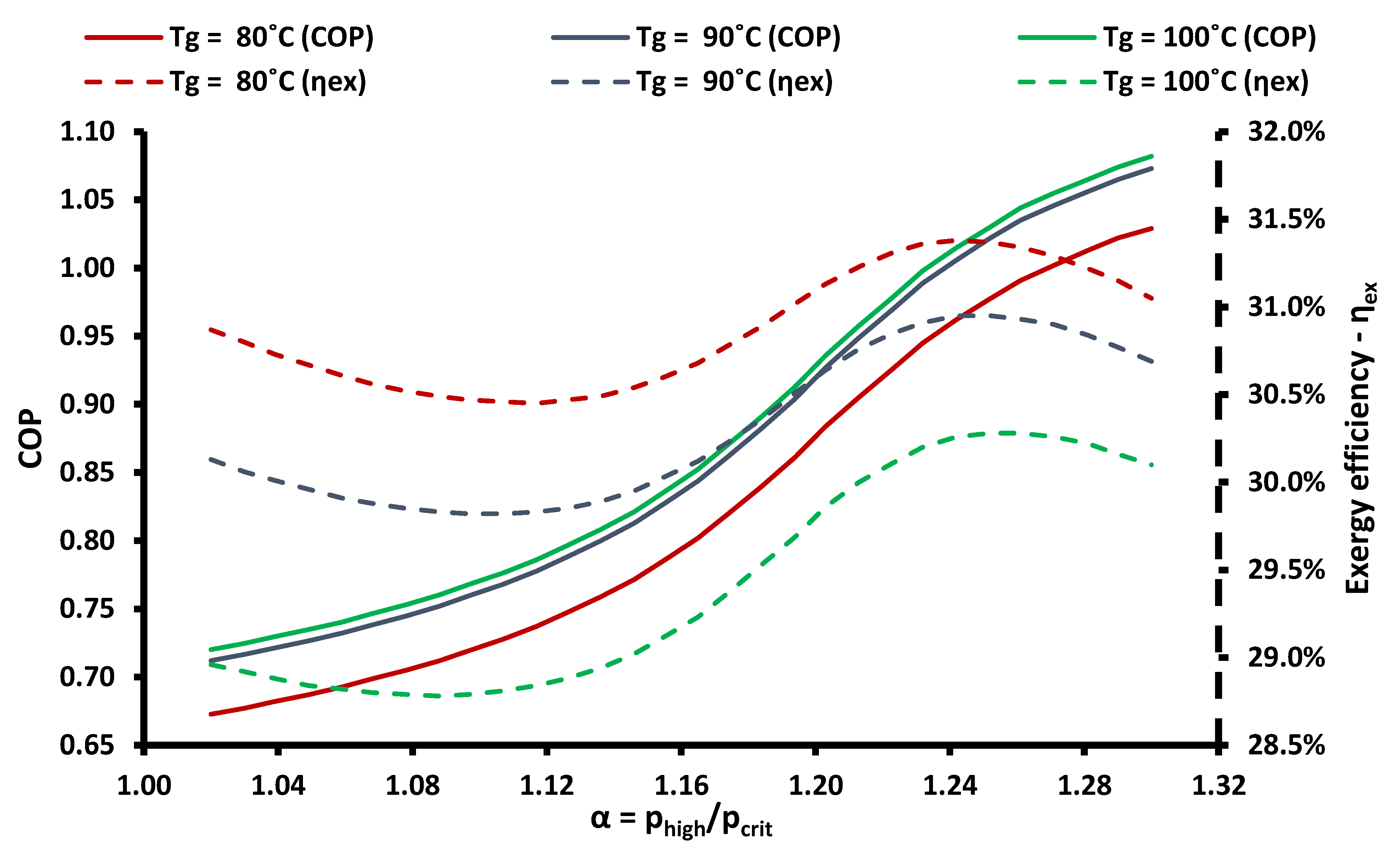
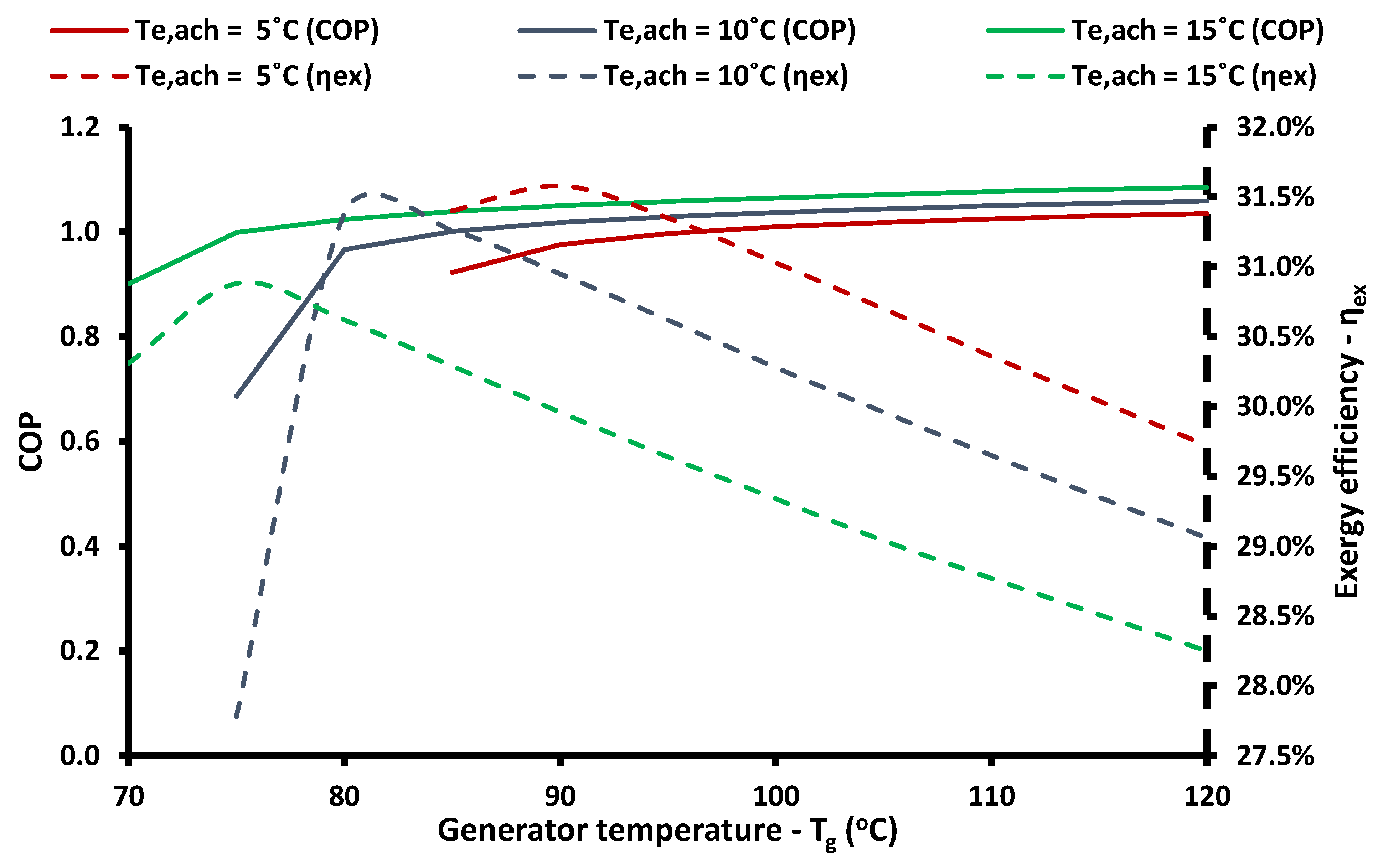
3.3. Absorption Chiller Subcooling System Performance

The use of the absorption chiller for dedicated subcooling is a choice that means the consumption of extra heat input in the system but not extra work, as is the case in the mechanical subcooling case. So, the reduction in the overall work consumption of the system can be higher than in the M-SC system. However, there is a need for significant amounts of heat input in the generator of the absorption chiller. The optimization of the ACH-SC system was performed using three optimization variables; the pressure ratio parameter (a), the evaporator temperature of the absorption chiller (Te,ach), and the generator temperature level (Tg).
Figure 12 illustrates the COP of the ACH-SC system and of the Ref system for all the optimized operating scenarios. It was obvious that the Ref system leads to higher COP compared to the ACH-SC system for all the cases. The reason for this result is based on the definition of COP according to Equation (9). This equation evaluates the work and the heat input in the same way by simply adding them in the denominator of the COP. The heat input in the generator is generally high and this fact leads to reduced COP. It is remarkable to state that the curves of the ACH-SC system were not very smooth in all cases because of restrictions in the optimization procedure. These restrictions are mainly associated with the minimum possible evaporator temperature (Te,ach), as well the minimum possible generation temperature in every case, because of restrictions in the LiBr concentration in the streams of the absorption cycle.
On the other hand, the exergy efficiency of the system was enhanced in the ACH-SC system compared to the Ref system, according to Figure 13. The enhancements were significant and so it can be said that the ACH-SC system is a system with important exegetic enhancement. The exergy efficiency was the proper criterion for evaluating the ACH-SC system because the temperature level of the generator heat input was not considered with the simplistic energetic index (COP). It is important to state that the overall maximum exergy efficiency was 37.23% and it was found for (Te = −15 °C and Tc = 35 °C), whereas for this case the COP was 2.121. Moreover, it has to be said that the optimum evaporating temperatures were equal to −25 °C for heat rejection temperatures higher than 35 °C. It can be said that the optimum refrigeration temperatures were lower for the ACH-SC system compared to the Ref system, a result which was also found for the M-SC system. So, it can be said that, for both dedicated subcooling technologies, the optimum operating refrigeration temperature is lower in the subcooling systems, according to exegetic criteria.
The next step in this analysis was the investigation of the optimization variables in the ACH-SC system for the scenario (Te = −15 °C and Tc = 40 °C). Figure 14 shows that higher values of the pressure ratio parameter increased the COP, but the optimum exergy efficiency was found for (α = 1.24). Moreover, in this case, the optimum generator temperature was 80 °C, while the absorption chiller evaporator temperature was kept at 10 °C. It has to be said that the subcooling was more beneficial in the cases of higher-pressure ratio, and the COP increased with a higher rate of higher-pressure ratio values. Practically, in high-pressure levels, there is greater gain with the subcooling because of the inclination in the liquid saturation curve of the CO2. The exergy efficiency curves were not maximized in the higher-pressure ratio, but, rather, in lower values, because in extremely high-pressure levels, the compressor work is high and this has a strong impact of the exergy efficiency values.
Figure 15 proves that higher generator temperatures increase the system COP, but the exergy efficiency was maximized for a specific generator temperature in every case. The optimum generator temperature was 90 °C for Te,ach = 5 °C, 80 °C for Te,ach = 10 °C, and 75 °C for Te,ach = 15 °C. The global optimum was found for (Te,ach = 5 °C and Tg = 80 °C). These results indicate the need for a detailed optimization procedure in every case, and they also verify the reasons for selecting the present optimization variables. Lastly, it has to be said that the results of Figure 15 regard the optimum pressure ratio parameter in every case.

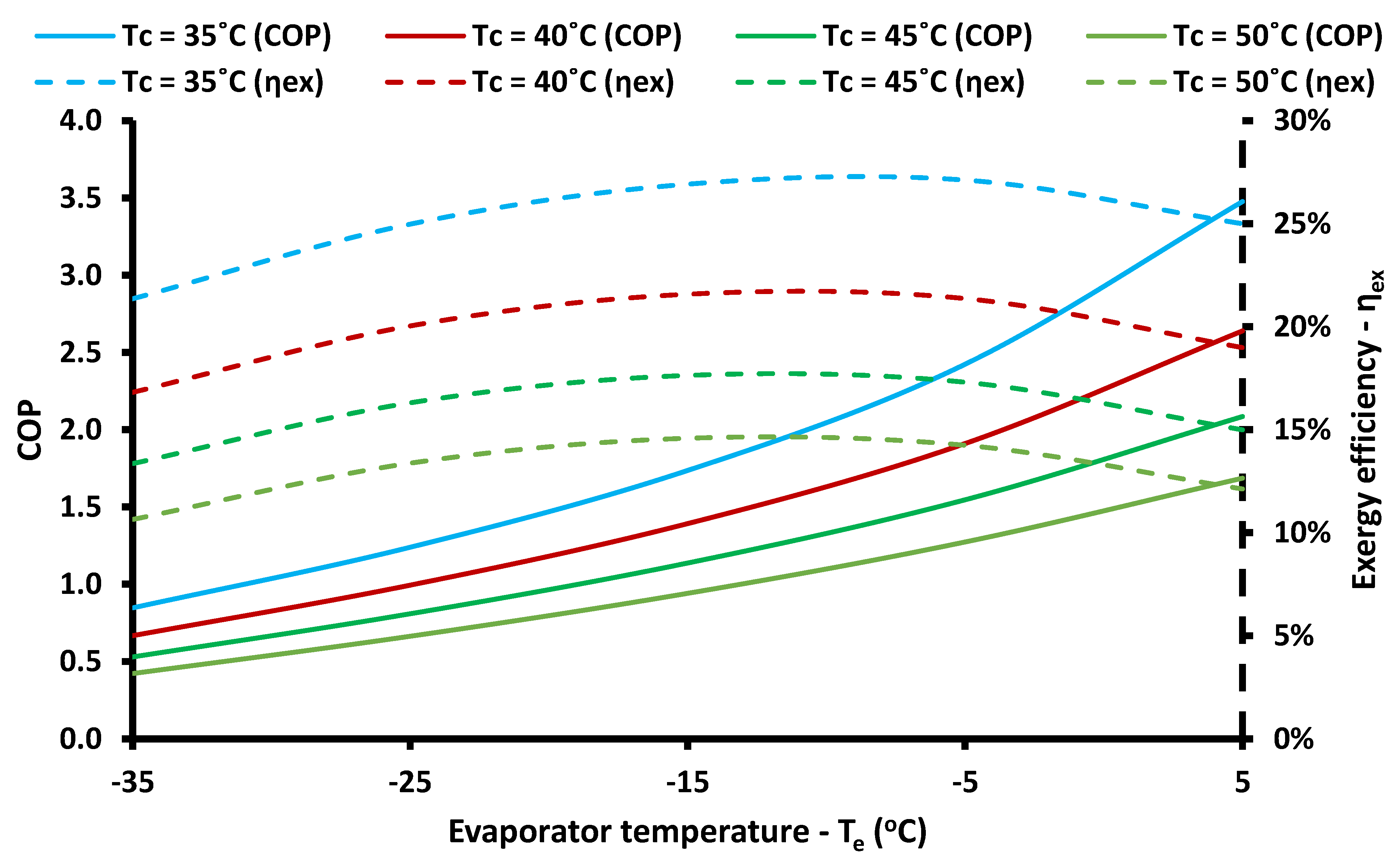
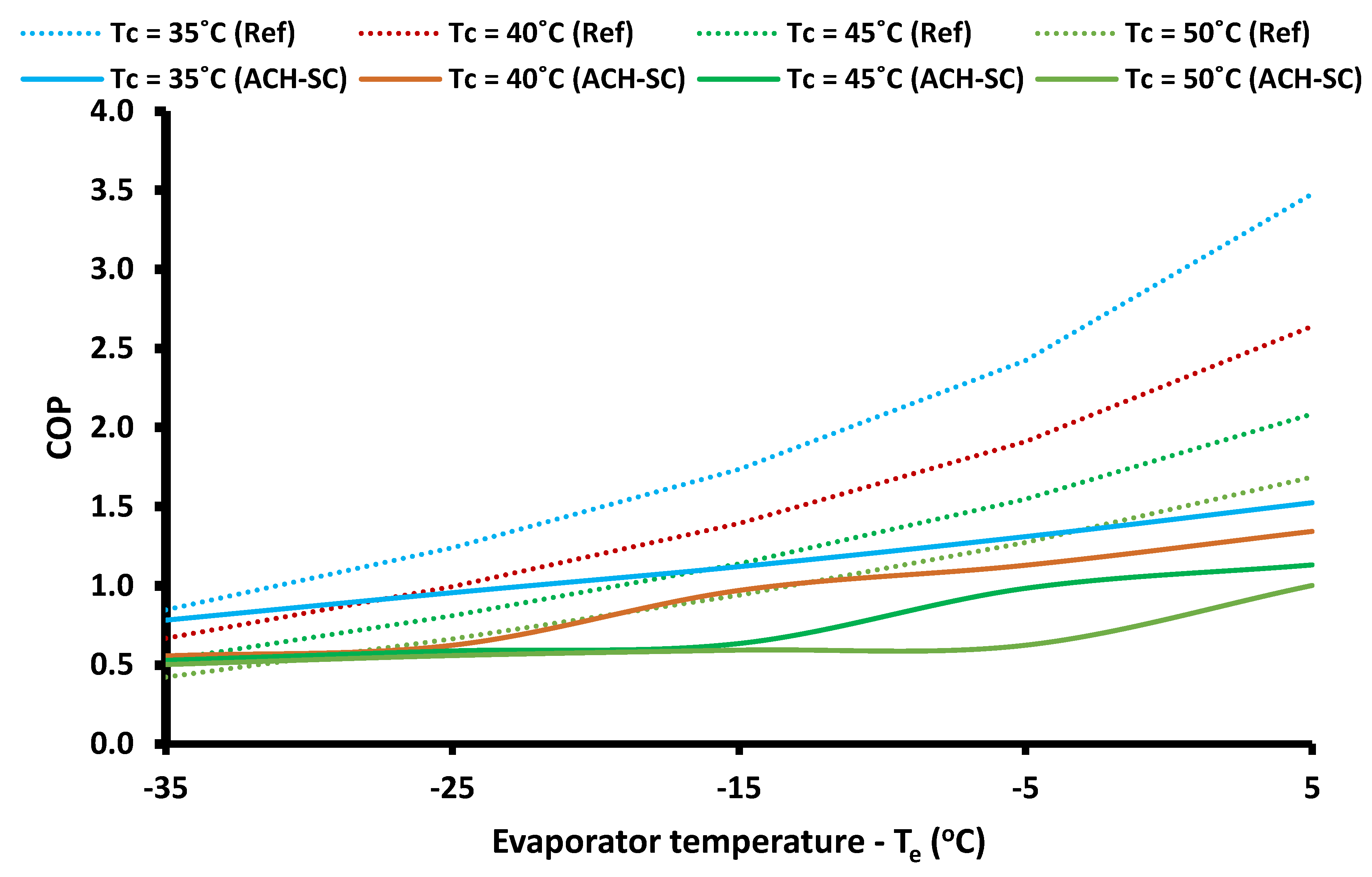
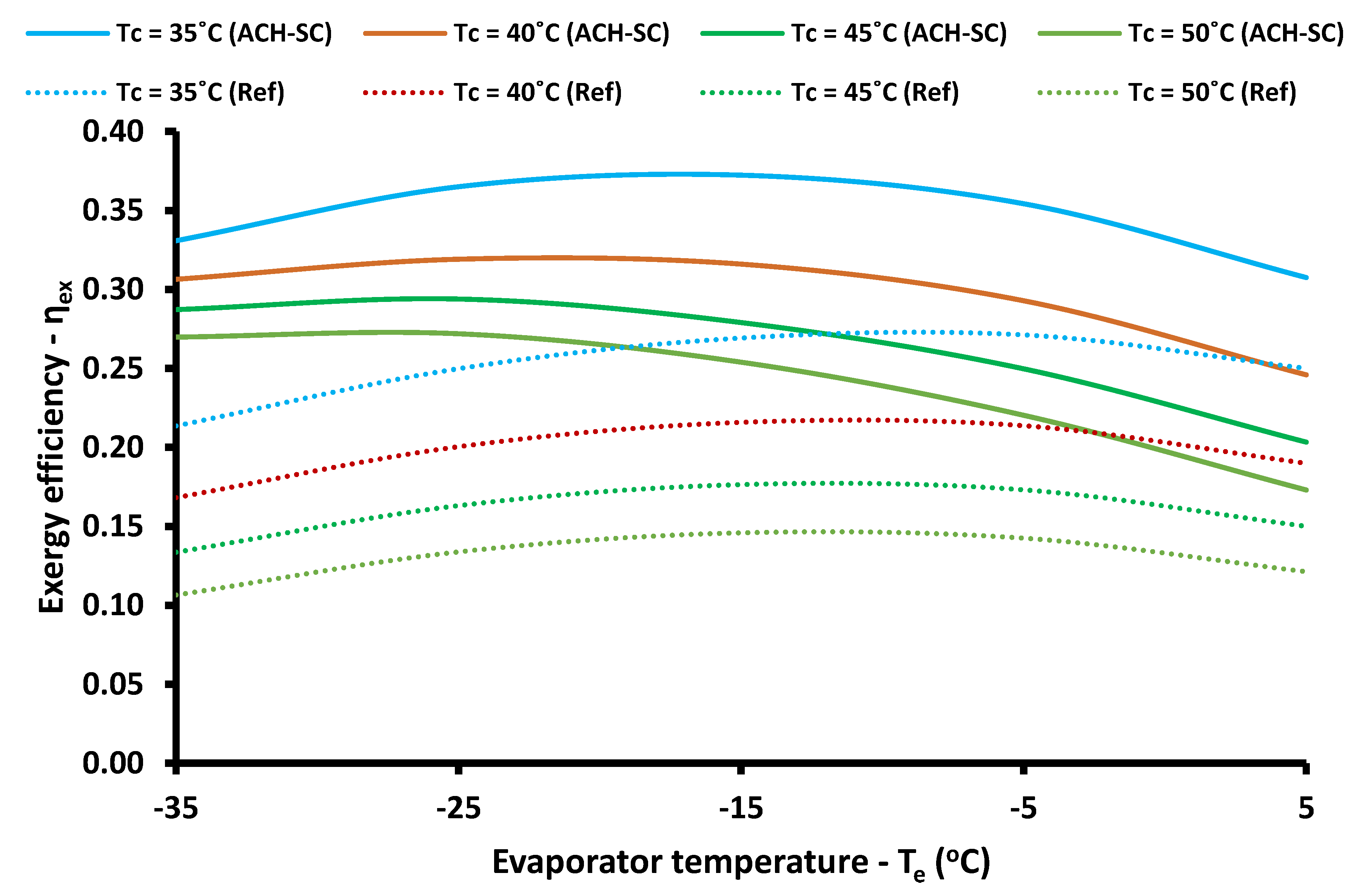
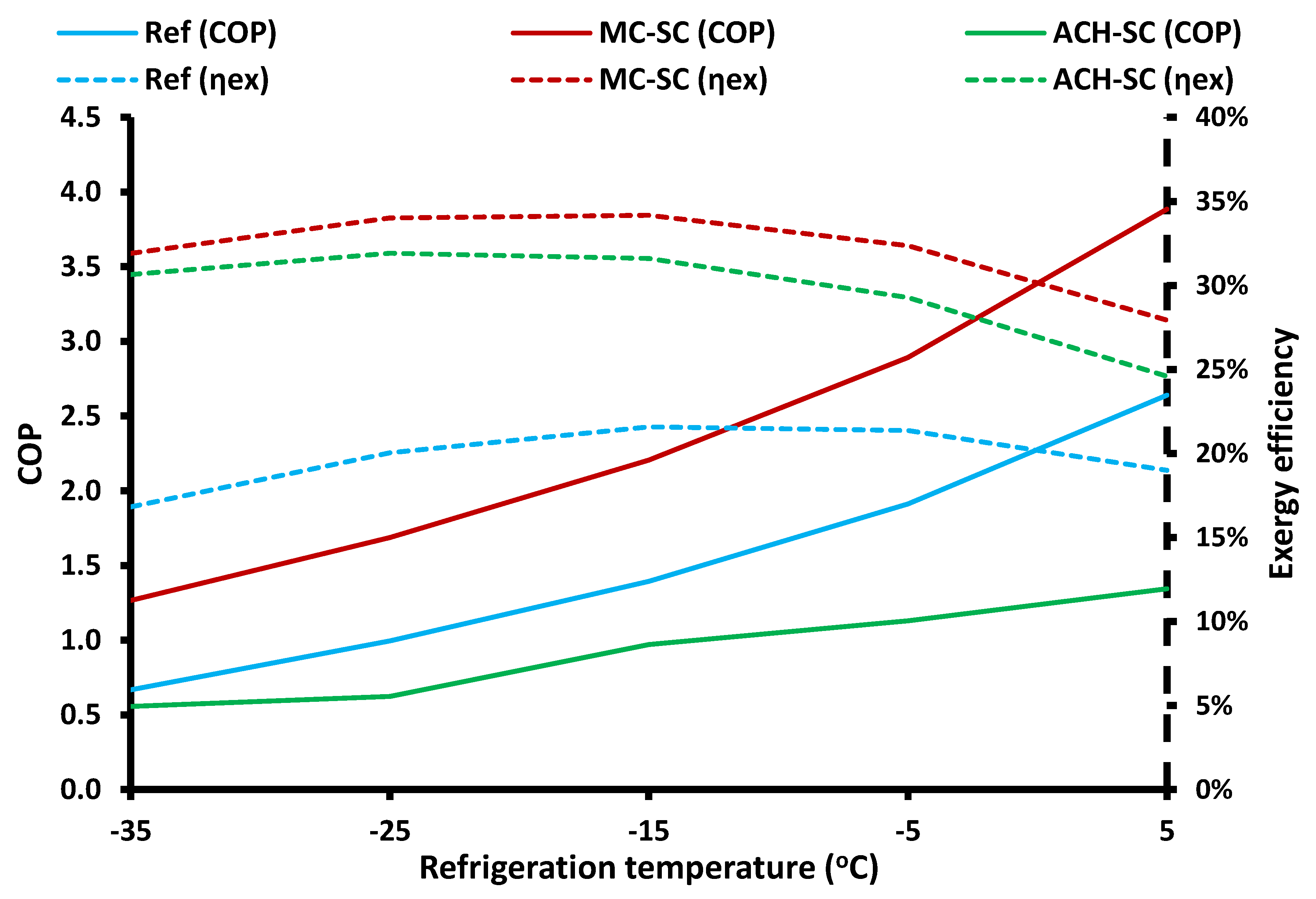
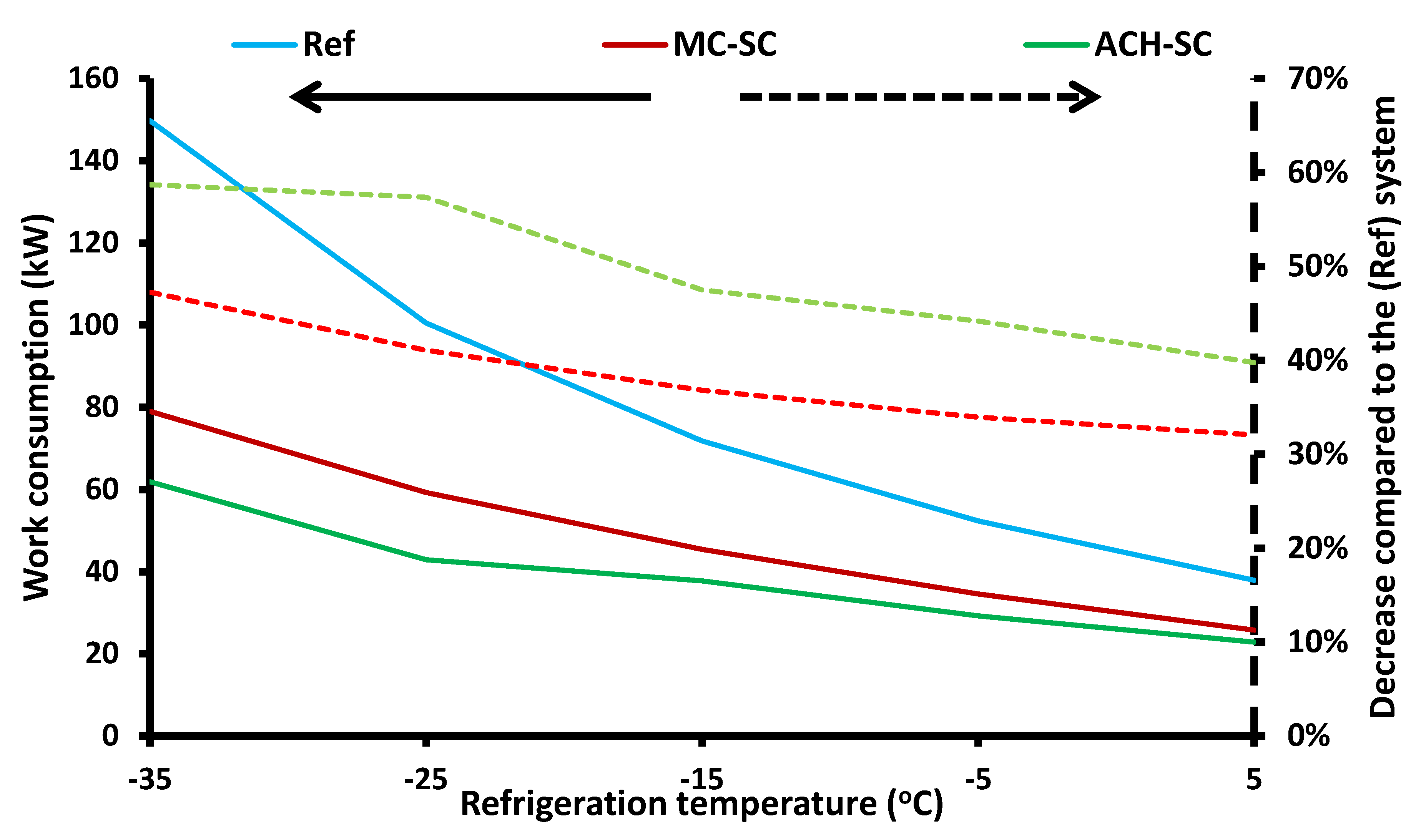
3.4. Comparative Analysis

The last step in this analysis was the comparison of the three examined configurations. Firstly, the three systems were compared for different refrigeration temperatures and for the typical heat rejection temperature of 40 °C. Figure 16 and Figure 17 show the COP, the exergy efficiency, and the work consumption of the examined systems, respectively.
Figure 16 shows that the M-SC system had the highest COP for all the cases, while the Ref system and the ACH-SC system followed, respectively. The low COP of the ACH-SC system is explained by the definition of its COP, which evaluates, with the same way, the work consumption and the heat input. Moreover, Figure 16 depicts the exergy efficiency of the examined systems. The highest exergy efficiency was found for the M-SC system, with the ACH-SC system as the second choice with a small difference, while the Ref system had significantly lower exergy efficiency compared to the systems with subcooling. The greatest difference was observed in the lower refrigeration temperatures, because in these cases the reference system faces important difficulties to produce the demanded refrigeration load, due to the high-pressure ratio in the compressor and the lack of any subcooling assistance.
Figure 17 shows the work consumption for the three systems, as well as the decrease in the work consumption of the system with subcooling compared to the reference system. It was obvious that the highest work consumption was found for the Ref system, whereas the ACH-SC system had the lowest work consumption. The decrease in the work consumption for the ACH-SC system ranged from 40% to 59%, whereas for the M-SC system it ranged from 32% to 41%. So, it can be said that the ACH-SC system leads to higher work savings compared to the M-SC system, and this is an important advantage of this configuration.
Another advantage of the ACH-SC system is the use of the environmentally friendly working pair, LiBr-H2O, while, in this case, the M-SC system utilizes R134a, which has a GWP of 1430. However, there is the possibility to use other working fluids in the M-SC system, such as propane or butane, which have extremely low GWP (around 3~4), but they are flammable working fluids and they belong in the ASHRAE safety group A3. Generally, there is no optimum choice for the secondary cycle, and this is something that has been also discussed in the recent review paper of Ciconkov [4].
The results for all the cases are given in Figure 18, Figure 19 and Figure 20 for the COP, the exergy efficiency, and the work consumption, respectively. Moreover, Table 2 includes the results of work and the heat input in the system for all the examined cases. It has to be said that the work input was significant and it ranged from 51.14 up to 137 kW, whereas the refrigeration production was constant at 100 kW in all the cases. The greater heat input in the system was found for the cases with high heat rejection temperature levels (Tc = 45 °C or 50 °C), thus, in these cases, the absorption chiller was not the most suitable case. The highest work consumption decrease was found in the cases with extremely low refrigeration temperatures (e.g., Te = −35 °C). Thus, the ACH-SC is the best choice for operating scenarios with low refrigeration temperatures and relatively low heat rejection temperatures. In other words, the ACH-SC system can be applied in low-temperature level refrigeration cases and in climates without extremely high ambient temperatures.
Table 3 gives, clearly, the deviation in the COP and the exergy efficiency of the systems with subcooling compared to the reference system. It has to be said that the exergy efficiency of the system with subcooling was enhanced compared to the reference system, and this is the critical result which proves that subcooling is beneficial in any case. In regards to the COP index, this was enhanced in the case of the mechanical subcooling, but it was decreased in the case of the absorption chiller. The reason for the decrease in the case with the absorption chiller is the definition of the COP in this case (see Equation (9)); the generator heat input is simply added to the work consumption. Thus, this index was not the best one for the evaluation of the system with the absorption chiller, but it was given in order to present both energy and exergy indexes in this work and to make a complete work. So, it is critical to state again that the exergy efficiency is the one which evaluates the heat input as the equivalent work consumption and thus it has to be taken into consideration in the final evaluation of any system.
Furthermore, it has to be said that the mean work consumption decrease was 41.39% with the M-SC system, and with the ACH-SC system it was 53.83%, by taking into account all the examined operating scenarios. These are important values that have to be taken into consideration for the future designs of the CO2 transcritical systems. Moreover, it has to be said that the values in the literature about the enhancement with the M-SC system are about 30% [23]; however, this study found slightly higher values because of the detailed optimization procedures.
In regards to the comparison of the two subcooling cases in the financial point of view, it has to be said that the investment cost of the absorption chiller is higher than the mechanical compression system, thus the use of the M-SC system would be a better choice financially. The difference between electricity consumption was not high enough between the two cases in order to be able to cover the great investment cost of the absorption machine. However, if, in the future, the electricity cost increased, the absorption chiller would be a less expensive technology due to its maturity; and then, maybe, the ACH-SC system would be competitive financially.
Lastly, it has to be said that the use of renewable energy sources, such as solar energy, can be applied in order to cover the energy needs of the dedicated subcooling systems. Photovoltaic panels can be used in the case of dedicated mechanical subcooling, and solar thermal systems can be used in the case of dedicated subcooling with an absorption chiller. The hybrid operation with solar energy gives the potential for an environmentally friendlier design, which could provide an opportunity for future “state of the art” refrigeration systems.
For the present analysis, it can be said that the collecting area of photovoltaic panels, in order to cover the electricity demand of the mechanical subcooling compressor, will have to be about 110 m2 by assuming a mean electrical efficiency of 12% [48] and mean solar irradiation of 800 W/2. On the other hand, about 135 m2 of evacuated tubes are needed for covering the heat input demand of the system with the absorption chiller, if a collector efficiency of 60% [43] and 800 W/m2 of solar irradiation are assumed. The previous simple calculations are in relation to an operation with a refrigeration load of 100 kW at the typical case of Te = −15 °C and Tc = 40 °C. However, it has to be said that the use of solar collectors increase the investment cost of the system and thus it is something that it has to be taken into consideration. In the future, there is a need for detailed studies that can optimize financially the suggested configurations and simultaneously to take into account the environmental gain by the reduction of grid electricity consumption.

4. Conclusions

The objective of this work was to investigate the use of dedicated subcooling techniques in a CO2 transcritical refrigeration cycle. The use of an external mechanical compression refrigeration cycle and an absorption chiller for subcooling the CO2 after the gas cooler were examined for different operating scenarios. All the cases were optimized and the results were compared under the proper conditions. The analysis was conducted with developed models in Engineering Equations Solver which were validated with literature data. The most important conclusions of this work are summarized below:
-
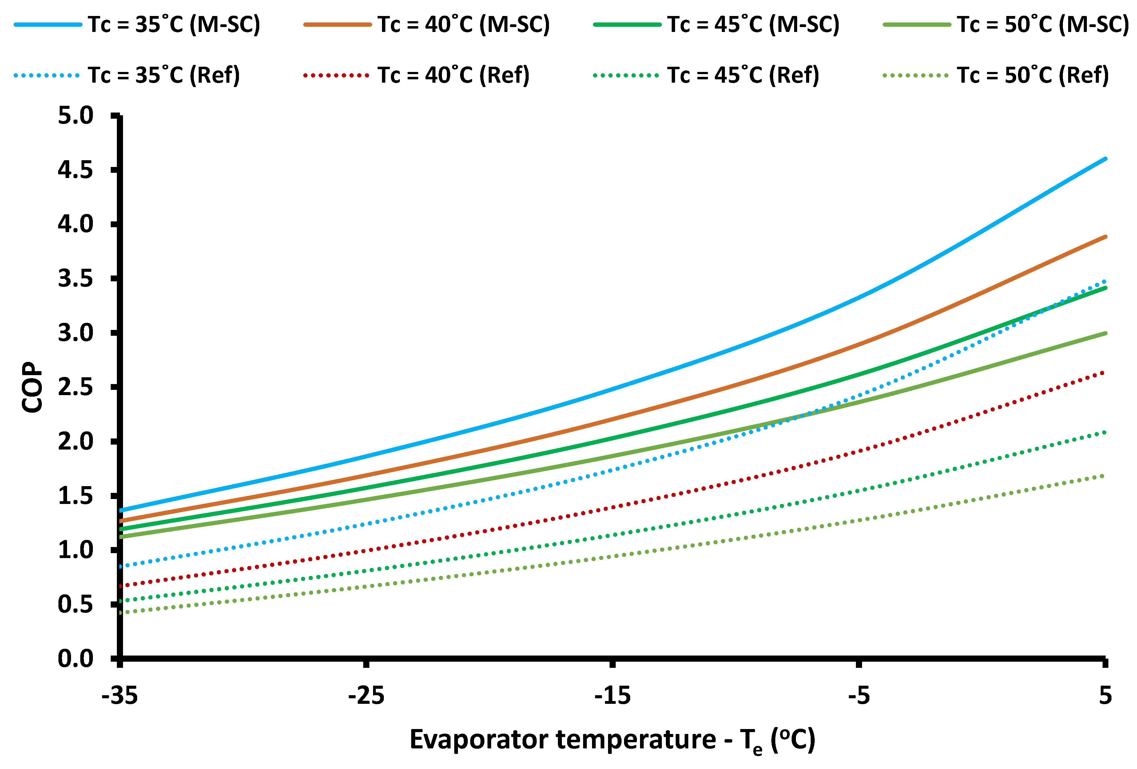
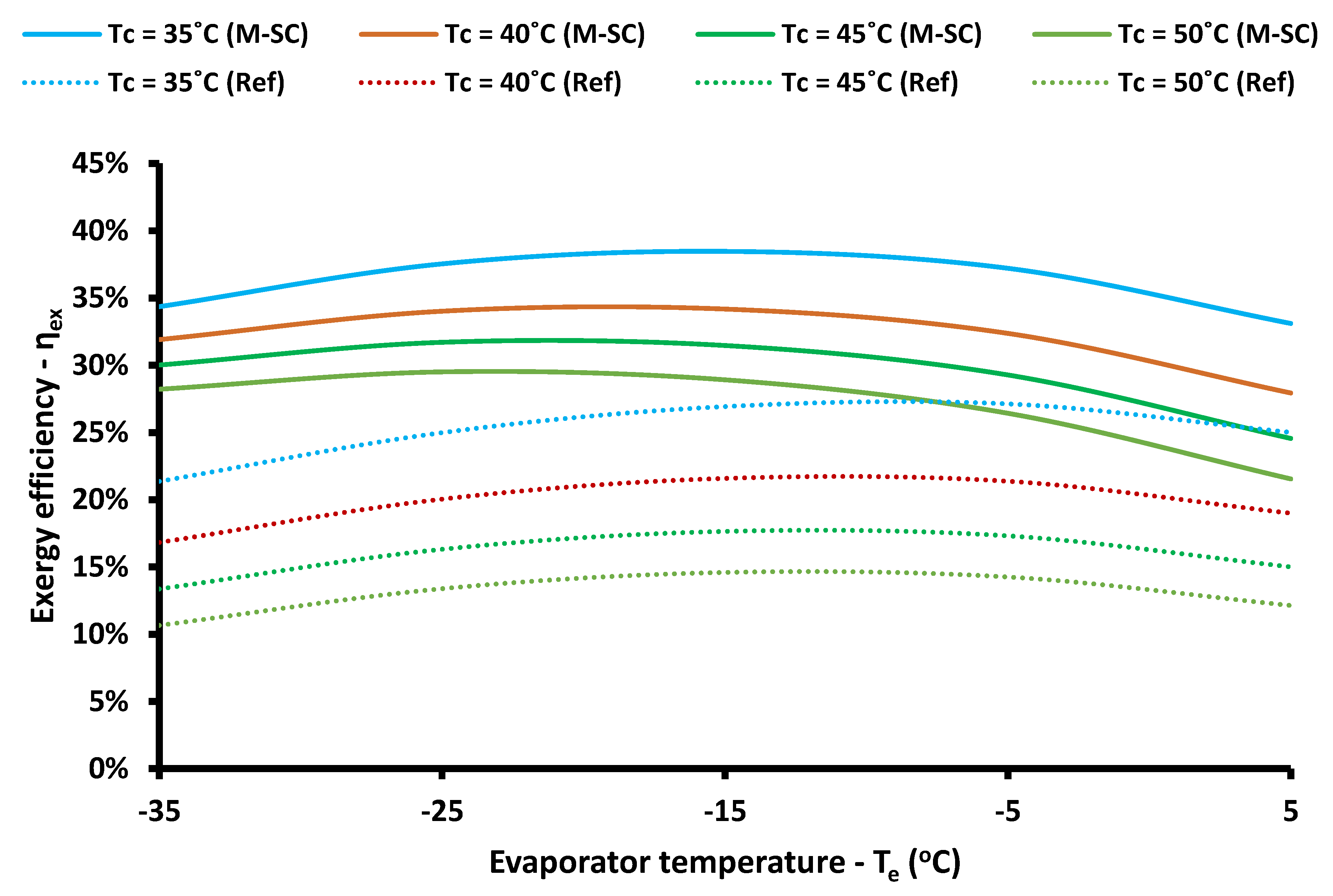
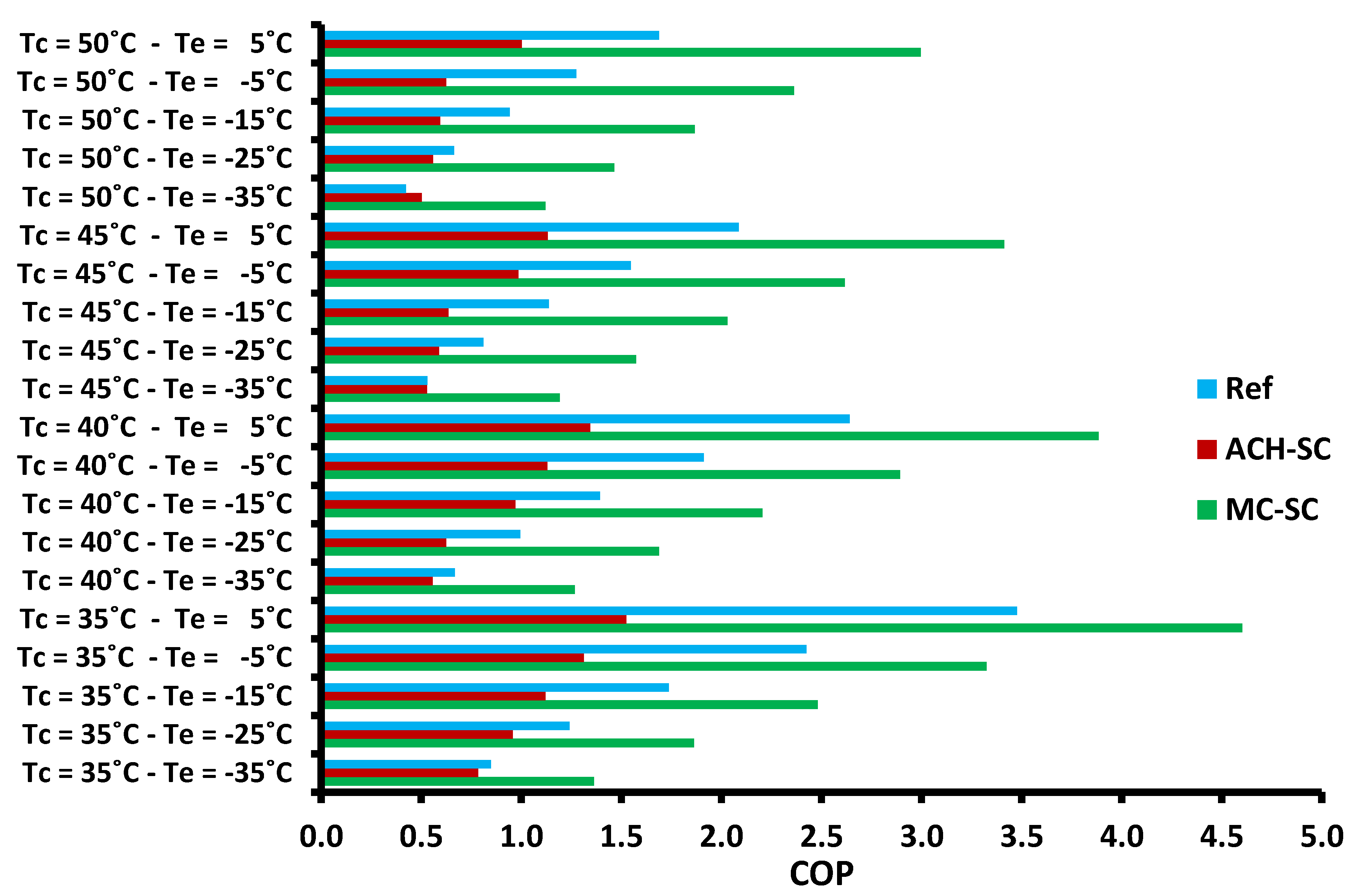
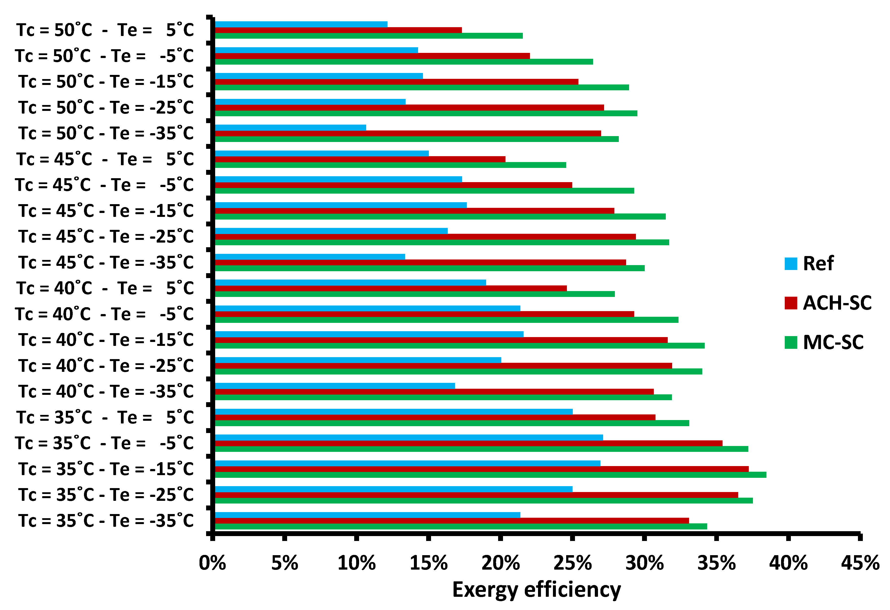
The use of dedicated subcooling with the mechanical compression (M-SC) system leads to higher COP and to higher exergy efficiency compared to the reference (Ref) system.
-
The use of dedicated subcooling with the absorption chiller (ACH-SC) system leads to lower COP and to higher exergy efficiency compared to the reference (Ref) system.
-
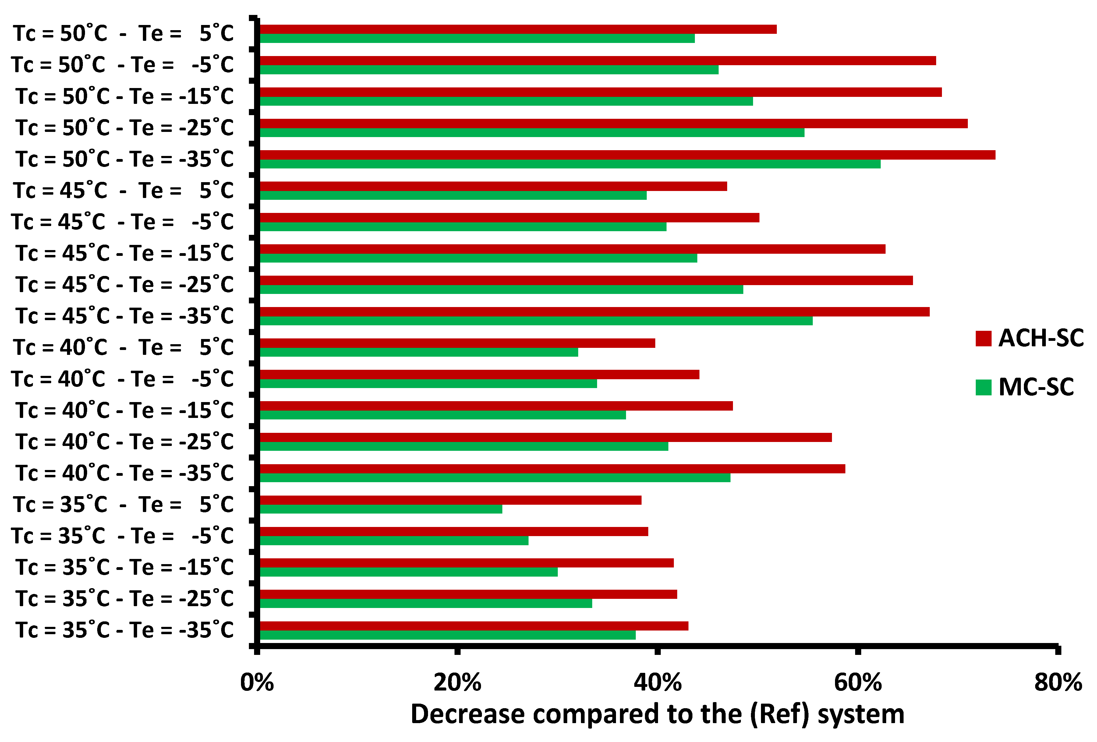
The mean decrease in the work consumption is found to be 41.39% for the mechanical subcooling system and 53.83% with the absorption chiller subcooling system.
-
The heat input in the absorption chiller ranged from 51 up to 137 kW. Generally, it is high for cases with high heat rejection temperature levels.
-
The exergy efficiency of the ACH-SC system is a bit lower than the M-SC system, but the electricity savings are higher in the ACH-SC. These facts in combination with the environmental parameters have to be taken into consideration for the future design of the dedicated subcooling systems. Moreover, the availability of any heat source (e.g., solar systems, geothermal energy, or waste heat) is an extra parameter for the final selection.

Author Contributions

The authors of this work have the same contribution.

Funding

This research was funded by “Bodossaki Foundation”.

Acknowledgments

Evangelos Bellos would like to thank “Bodossaki Foundation” for its financial support.

Conflicts of Interest

The authors declare no conflict of interest.

Nomenclature

COPCoefficient of performance
hSpecific enthalpy, kJ kg−1 K−1
mMass flow rate, kg s−1
pPressure, bar
QHeat rate, kW
QeRefrigeration production, kW
QgGenerator heat input, kW
rCompression pressure ratio
TTemperature, °C
TcHeat rejection temperature, °C
T0Reference temperature, K
WWork consumption in the CO2 compressor, kW
WscWork consumption in the subcooling compressor, kW
XLiBr concentration in the solution, %
Greek Symbols
αPressure ratio
ΔTscSubcooling temperature difference, °C
ηexExergy efficiency
ηhexSolution heat exchanger effectiveness
ηisIsentropic efficiency of the compressor
Subscripts and Superscripts
aabsorber
concondenser
critcritical
expexperimental
e,achevaporator of the absorption chiller
e,mevaporator of the mechanical subcooling system
ggenerator
highhigh
isisentropic
lowlow
rrefrigerant (water)
SCsubcooling
strstrong solution
simsimulation
wweak solution
Abbreviations
ACH-SCSystem with absorption chiller subcooling
EESEngineering Equation Solver
GWPGlobal warming potential
M-SCSystem with mechanical subcooling
RefReference system

Appendix A. Absorption Chiller Modeling

This appendix is devoted to presenting the modeling of the absorption chiller in this work. Figure A1 depicts the examined absorption chiller, which is a single-effect absorption machine operating with a LiBr-H2O working pair. This system has an internal heat exchanger in order to have higher performance. The evaporator is the device that is coupled to the CO2 refrigeration system and the subcooling is performed with this device. The generator is the device that needs the heat input from an external heat source, while the condenser and the absorber reject heat to the environment. Below, the main mathematical modeling of the absorption is given. More details can be found in [42,43,44] about this modeling.
Firstly, it has to be said that the subcooling in the CO2 cycle is produced by the absorption chiller evaporator. So, it can be written:
Q e , ach = m r ( h j h i )
The energy balance in the generator can be written as below:
Q g = m r h g + m str h d m w h c
The energy balance in the absorber can be written as below:
Q a = m r h j + m str h f m w h a
The energy balance in the condenser can be written as below:
Q con = m r ( h h h g )
The heat exchanger effectiveness (ηhex) is defined as below:
η hex = h d h e h d h b
It has to be said that this definition gives slightly higher heat transfer rates compared to the definition with the respective temperatures.
The energy balance in the heat exchanger can be written as below:
m w ( h c h b ) = m str ( h d h e )
The work input in the circulation pump is neglected, so it can be written:
h b = h a
The enthalpy is conserved in the throttling valves, so it can be written:
h f = h e
h i = h h
The temperature levels in the absorber and the condenser are assumed to be the same:
T con = T a
At this point, it has to be said that the temperature (Ta) is the saturation temperature of the weak solution at the low pressure inside the absorber.
The total mass flow rate balance in the generator can be written as below:
m w = m str + m r
The mass flow rate balance about the LiBr substance in the generator can be written as below:
X w m w = X str m str
Moreover, it has to be said that the state point “j” is assumed to be saturated vapor, while the state point “h” to be saturated liquid.
Figure A1. The examined absorption chiller.
Applsci 09 01605 g0a1

References

  1. Wang, J.; Shang, S.; Li, X.; Wang, B.; Wu, W.; Shi, W. Dynamic Performance Analysis for an Absorption Chiller under Different Working Conditions. Appl. Sci. 2017, 7, 797. [Google Scholar] [CrossRef]
  2. Bellos, E.; Tzivanidis, C. Investigation of the Environmentally-Friendly Refrigerant R152a for Air Conditioning Purposes. Appl. Sci. 2019, 9, 119. [Google Scholar] [CrossRef]
  3. European Commission. Regulation (EU) No 517/2014 of the European Parliament and of the Council of 16th April 2014 on Fluorinated Greenhouse Gases and Repealing Regulation (EC) No 842/2006; European Commission: Brussels, Belgium, 2014. [Google Scholar]
  4. Ciconkov, R. Refrigerants: There is still no vision for sustainable solutions. Int. J. Refrig. 2018, 86, 441–448. [Google Scholar] [CrossRef]
  5. Llopis, R.; Sánchez, D.; Cabello, R.; Catalán-Gil, J.; Nebot-Andrés, L. Conversion of a Direct to an Indirect Refrigeration System at Medium Temperature Using R-134a and R-507A: An Energy Impact Analysis. Appl. Sci. 2018, 8, 247. [Google Scholar] [CrossRef]
  6. Abas, N.; Kalair, A.R.; Khan, N.; Haider, A.; Saleem, Z.; Saleem, M.S. Natural and synthetic refrigerants, global warming: A review. Renew. Sustain. Energy Rev. 2018, 90, 557–569. [Google Scholar] [CrossRef]
  7. Gullo, P.; Elmegaard, B.; Cortella, G. Energy and environmental performance assessment of R744 booster supermarket refrigeration systems operating in warm climates. Int. J. Refrig. 2016, 64, 61–79. [Google Scholar] [CrossRef] [Green Version]
  8. Tsamos, K.M.; Ge, Y.T.; Santosa, I.; Tassou, S.A.; Bianchi, G.; Mylona, Z. Energy analysis of alternative CO2 refrigeration system configurations for retail food applications in moderate and warm climates. Energy Convers. Manag. 2017, 150, 822–829. [Google Scholar] [CrossRef]
  9. Purohit, N.; Gupta, D.K.; Dasgupta, M.S. Energetic and economic analysis of trans-critical CO2 booster system for refrigeration in warm climatic condition. Int. J. Refrig. 2017, 80, 182–196. [Google Scholar] [CrossRef]
  10. Chen, Y.; Gu, J. The optimum high pressure for CO2 transcritical refrigeration systems with internal heat exchangers. Int. J. Refrig. 2005, 28, 1238–1249. [Google Scholar] [CrossRef]
  11. Torrella, E.; Sánchez, D.; Llopis, R.; Cabello, R. Energetic evaluation of an internal heat exchanger in a CO2 transcritical refrigeration plant using experimental data. Int. J. Refrig. 2011, 34, 40–49. [Google Scholar] [CrossRef]
  12. Cavallini, A.; Cecchinato, L.; Corradi, M.; Fornasieri, E.; Zilio, C. Two-stage transcritical carbon dioxide cycle optimisation: A theoretical and experimental analysis. Int. J. Refrig. 2005, 28, 1274–1283. [Google Scholar] [CrossRef]
  13. Sarkar, J.; Agrawal, N. Performance optimization of transcritical CO2 cycle with parallel compression economization. Int. J. Therm. Sci. 2010, 49, 838–843. [Google Scholar] [CrossRef]
  14. Gullo, P.; Elmegaard, B.; Cortella, G. Energetic, Exergetic and Exergoeconomic Analysis of CO2 Refrigeration Systems Operating in Hot Climates. In Proceedings of the ECOS 2015: 28th International Conference on Efficiency, Cost, Optimization, Simulation and Environmental Impact of Energy Systems, Pau, France, 29 June–3 July 2015. [Google Scholar]
  15. Chesi, A.; Esposito, F.; Ferrara, G.; Ferrari, L. Experimental analysis of R744 parallel compression cycle. Appl. Energy 2014, 135, 274–285. [Google Scholar] [CrossRef]
  16. Nakagawa, M.; Marasigan, A.R.; Matsukawa, T.; Kurashina, A. Experimental investigation on the effect of mixing length on the performance of two-phase ejector for CO2 refrigeration cycle with and without heat exchanger. Int. J. Refrig. 2011, 34, 1604–1613. [Google Scholar] [CrossRef]
  17. Chen, G.; Volovyk, O.; Zhu, D.; Ierin, V.; Shestopalov, K. Theoretical analysis and optimization of a hybrid CO2 transcritical mechanical compression—Ejector cooling cycle. Int. J. Refrig. 2017, 74, 86–94. [Google Scholar] [CrossRef]
  18. Yang, J.L.; Ma, Y.T.; Liu, S.C. Performance investigation of transcritical carbon dioxide two-stage compression cycle with expander. Energy 2007, 32, 237–245. [Google Scholar] [CrossRef]
  19. Megdouli, K.; Tashtoush, B.M.; Ezzaalouni, Y.; Nahdi, E.; Mhimid, A.; Kairouani, L. Performance analysis of a new ejector expansion refrigeration cycle (NEERC) for power and cold: Exergy and energy points of view. Appl. Thermal Eng. 2017, 122, 39–48. [Google Scholar] [CrossRef]
  20. Sanchez, D.; Llopis, R.; Cabello, R.; Catalán-Gil, J.; Nebot-Andrés, L. Conversion of a direct to an indirect commercial (HFC134a/CO2) cascade refrigeration system: Energy impact analysis. Int. J. Refrig. 2017, 73, 183–199. [Google Scholar] [CrossRef]
  21. Megdouli, K.; Ejemni, N.; Nahdi, E.; Mhimid, A.; Kairouani, L. Thermodynamic analysis of a novel ejector expansion transcritical CO2/N2O cascade refrigeration (NEETCR) system for cooling applications at low temperatures. Energy 2017, 128, 586–600. [Google Scholar] [CrossRef]
  22. Ma, M.; Yu, J.; Wang, X. Performance evaluation and optimal configuration analysis of a CO2/NH3 cascade refrigeration system with falling film evaporator–condenser. Energy Convers. Manag. 2014, 79, 224–231. [Google Scholar] [CrossRef]
  23. Llopis, R.; Nebot-Andrés, L.; Sánchez, D.; Catalán-Gil, J.; Cabello, R. Subcooling methods for CO2 refrigeration cycles: A review. Int. J. Refrig. 2018, 93, 85–107. [Google Scholar] [CrossRef]
  24. Llopis, R.; Cabello, R.; Sánchez, D.; Torrella, E. Energy improvements of CO2 transcritical refrigeration cycles using dedicated mechanical subcooling. Int. J. Refrig. 2015, 55, 129–141. [Google Scholar] [CrossRef]
  25. Llopis, R.; Nebot-Andrés, L.; Cabello, R.; Sánchez, D.; Catalán-Gil, J. Experimental evaluation of a CO2 transcritical refrigeration plant with dedicated mechanical subcooling. Int. J. Refrig. 2016, 69, 361–368. [Google Scholar] [CrossRef]
  26. Nebot-Andres, L.; Llopis, R.; Sánchez, D.; Catalán-Gil, J.; Cabello, R. CO2 with Mechanical Subcooling vs. CO2 Cascade Cycles for Medium Temperature Commercial Refrigeration Applications Thermodynamic Analysis. Appl. Sci. 2017, 7, 955. [Google Scholar] [CrossRef]
  27. Dai, B.; Liu, S.; Li, H.; Sun, Z.; Song, M.; Yang, Q.; Ma, Y. Energetic performance of transcritical CO2 refrigeration cycles with mechanical subcooling using zeotropic mixture as refrigerant. Energy 2018, 150, 205–221. [Google Scholar] [CrossRef]
  28. Salajeghe, M.; Ameri, M. Effects of further cooling the gas cooler outlet refrigerant by an absorption chiller, on a transcritical CO2-compression refrigeration system. Int. J. Exergy 2016, 21, 110–125. [Google Scholar] [CrossRef]
  29. Mohammadi, S.M.H. Theoretical investigation on performance improvement of a low-temperature transcritical carbon dioxide compression refrigeration system by means of an absorption chiller after-cooler. Appl. Therm. Eng. 2018, 138, 264–279. [Google Scholar] [CrossRef]
  30. Mohammadi, K.; McGowan, J.G. A thermo-economic analysis of a combined cooling system for air conditioning and low to medium temperature refrigeration. J. Clean. Prod. 2019, 206, 580–597. [Google Scholar] [CrossRef]
  31. Cyklis, P. Two stage ecological hybrid sorption–compression refrigeration cycle. Int. J. Refrig. 2014, 48, 121–131. [Google Scholar] [CrossRef]
  32. Li, H.; Su, W.; Cao, L.; Chang, F.; Xia, W.; Dai, Y. Preliminary conceptual design and thermodynamic comparative study on vapor absorption refrigeration cycles integrated with a supercritical CO2 power cycle. Energy Convers. Manag. 2018, 161, 162–171. [Google Scholar] [CrossRef]
  33. Arora, A.; Singh, N.K.; Monga, S.; Kumar, O. Energy and exergy analysis of a combined transcritical CO2 compression refrigeration and single effect H2O-LiBr vapour absorption system. Int. J. Exergy 2011, 9, 453–471. [Google Scholar] [CrossRef]
  34. Sarkar, J. Performance optimization of transcritical CO2 refrigeration cycle with thermoelectric subcooler. Int. J. Energy Res. 2013, 37, 121–128. [Google Scholar] [CrossRef]
  35. Schoenfield, J.; Hwang, Y.; Radermacher, R. CO2 transcritical vapor compression cycle with thermoelectric subcooler. HVAC&R Res. 2012, 18, 297–311. [Google Scholar]
  36. Jamali, S.; Yari, M.; Mohammadkhani, F. Performance improvement of a transcritical CO2 refrigeration cycle using two-stage thermoelectric modules in sub-cooler and gas cooler. Int. J. Refrig. 2017, 74, 105–115. [Google Scholar] [CrossRef]
  37. Dai, B.; Liu, S.; Zhu, K.; Sun, Z.; Ma, Y. Thermodynamic performance evaluation of transcritical carbon dioxide refrigeration cycle integrated with thermoelectric subcooler and expander. Energy 2017, 122, 787–800. [Google Scholar] [CrossRef]
  38. Aprea, C.; Greco, C.; Maiorino, A. The application of a desiccant wheel to increase the energetic performances of a transcritical cycle. Energy Convers. Manag. 2015, 89, 222–230. [Google Scholar] [CrossRef]
  39. Aprea, C.; Greco, C.; Maiorino, A. The substitution of R134a with R744: An exergetic analysis based on experimental data. Int. J. Refrig. 2013, 36, 2148–2159. [Google Scholar] [CrossRef]
  40. F-Chart Software, Engineering Equation Solver (EES). 2015. Available online: http://www.fchart.com/ees (accessed on 15 October 2018).
  41. Brown, J.S.; Yana-Motta, S.F.; Domanski, P.A. Comparitive analysis of an automotive air conditioning systems operating with CO2 and R134a. Int. J. Refrig. 2002, 25, 19–32. [Google Scholar] [CrossRef]
  42. Bellos, E.; Tzivanidis, C. Performance analysis and optimization of an absorption chiller driven by nanofluid based solar flat plate collector. J. Clean. Prod. 2018, 174, 256–272. [Google Scholar] [CrossRef]
  43. Bellos, E.; Tzivanidis, C.; Symeou, C.; Antonopoulos, K.A. Energetic, exergetic and financial evaluation of a solar driven absorption chiller—A dynamic approach. Energy Convers. Manag. 2017, 137, 34–48. [Google Scholar] [CrossRef]
  44. Bellos, E.; Tzivanidis, C. Parametric analysis and optimization of a solar driven trigeneration system based on ORC and absorption heat pump. J. Clean. Prod. 2017, 161, 493–509. [Google Scholar] [CrossRef]
  45. Bellos, E.; Tzivanidis, C. A Theoretical Comparative Study of CO2 Cascade Refrigeration Systems. Appl. Sci. 2019, 9, 790. [Google Scholar] [CrossRef]
  46. Gullo, P.; Elmegaard, B.; Cortella, G. Advanced exergy analysis of a R744 booster refrigeration system with parallel compression. Energy 2016, 107, 562–571. [Google Scholar] [CrossRef] [Green Version]
  47. Bellos, E.; Tzivanidis, C.; Pavlovic, S.; Stefanovic, V. Thermodynamic investigation of LiCl-H2O working pair in a double effect absorption chiller driven by parabolic trough collectors. Therm. Sci. Eng. Prog. 2017, 3, 75–87. [Google Scholar] [CrossRef]
  48. Venkateswari, R.; Sreejith, S. Factors influencing the efficiency of photovoltaic system. Renew. Sustain. Energy Rev. 2019, 101, 376–394. [Google Scholar] [CrossRef]
Figure 1. The reference examined system (Ref) which is a simple transcritical refrigeration cycle.
Applsci 09 01605 g001
Figure 2. System with dedicated mechanical subcooling (M-SC).
Applsci 09 01605 g002
Figure 3. System with dedicated subcooling using an absorption chiller (ACH-SC). The quantity (Qe,ach) is the subcooling heat rate which is equal to the refrigeration load of the absorption chiller.
Applsci 09 01605 g003
Figure 4. Pressure-specific enthalpy diagrams: (a) for the reference system, and (b) for the systems with dedicated subcooling.
Applsci 09 01605 g004
Figure 5. COP and exergy efficiency of the reference system for the examined optimized scenarios.
Applsci 09 01605 g005
Figure 6. The impact of the pressure ratio parameter of the reference system in exergy efficiency. The black solid points show the maximum exergy efficiency and the dotted line shows the geometric location of the maximum values (Te = −15 °C).
Applsci 09 01605 g006
Figure 7. The impact of the pressure ratio parameter of the reference system exergy efficiency (Tc = 40 °C).
Applsci 09 01605 g007
Figure 8. The COP of the mechanical subcooling system compared to the reference case for all the examined optimized scenarios.
Applsci 09 01605 g008
Figure 9. The exergy efficiency of the mechanical subcooling system compared to the reference case for all the examined optimized scenarios.
Applsci 09 01605 g009
Figure 10. The exergy efficiency of the mechanical subcooling system for different values of the evaporator temperature and different pressure ratio parameters (Te = −15 °C and Tc = 40 °C).
Applsci 09 01605 g010
Figure 11. The exergy efficiency of the mechanical subcooling system for different values of the pressure ratio parameters and different evaporator temperatures (Te = −15 °C and Tc = 40 °C).
Applsci 09 01605 g011
Figure 12. The COP of the absorption chiller subcooling system compared to the reference case for all the examined optimized scenarios.
Applsci 09 01605 g012
Figure 13. The exergy efficiency of the absorption chiller subcooling system compared to the reference case for all the examined optimized scenarios.
Applsci 09 01605 g013
Figure 14. COP and exergy efficiency of the absorption chiller subcooling system for different pressure ratio parameters and generator temperature levels with (Te,ach = 10 °C, Te = −15 °C, and Tc = 40 °C).
Applsci 09 01605 g014
Figure 15. COP and exergy efficiency of the absorption chiller subcooling system for different generator temperature levels and evaporator temperatures with optimum pressure ratio values (Te = −15 °C and Tc = 40 °C).
Applsci 09 01605 g015
Figure 16. COP and exergy efficiency comparison of the optimized cases of the three systems (Tc = 40 °C).
Applsci 09 01605 g016
Figure 17. Work consumption of the optimized cases (continuous lines) of the three systems, and work consumption decrease of the subcooling cases compared to the reference case (non-continuous lines), (Tc = 40 °C).
Applsci 09 01605 g017
Figure 18. Comparison of the COP for the three systems and in all the optimized cases.
Applsci 09 01605 g018
Figure 19. Comparison of the exergy efficiency for the three systems and in all the optimized cases.
Applsci 09 01605 g019
Figure 20. Work consumption decrease with the subcooling cases compared to the reference case in all the examined optimized scenarios.
Applsci 09 01605 g020
Table 1. Checking the model validity using data from [25].
Initial DataResults
Te (°C)Phigh (bar)Tc (°C)ΔΤsc (°C)COPexpCOPsimDeviation
0.082.828.360.002.572.6121.63%
0.089.633.510.001.932.0636.89%
0.0102.641.690.001.321.3723.94%
−10.077.6270.001.911.8970.68%
−10.082.532.790.001.441.4772.57%
−10.0101.941.090.000.980.9334.80%
0.078.629.7113.282.853.0908.42%
0.081.634.7812.072.352.5819.83%
−10.077.333.4213.031.781.8282.70%
−10.0107.140.4815.621.271.2114.65%
Table 2. Work and the heat input demand for the examined operating scenarios for all the three examined refrigeration systems.
Examined ScenariosRefM-SCACH-SC
Work (kW)Work (kW)Work (kW)Heat (kW)
Tc = 35 °C-Te = −35 °C117.9573.3767.1760.58
Tc = 35 °C-Te = −25 °C80.6553.6846.8357.73
Tc = 35 °C-Te = −15 °C57.5740.2933.6255.55
Tc = 35 °C-Te = −5 °C41.2530.0825.1551.14
Tc = 35 °C-Te = 5 °C28.7621.7217.7247.86
Tc = 40 °C-Te = −35 °C149.7578.9961.85117.80
Tc = 40 °C-Te = −25 °C100.5259.2442.85117.40
Tc = 40 °C-Te = −15 °C71.7945.3537.6965.34
Tc = 40 °C-Te = −5 °C52.3334.5729.2259.27
Tc = 40 °C-Te = 5 °C37.8825.7422.8251.58
Tc = 45 °C-Te = −35 °C188.5083.9661.97127.10
Tc = 45 °C-Te = −25 °C123.5263.5742.68127.30
Tc = 45 °C-Te = −15 °C87.8749.2632.76124.70
Tc = 45 °C-Te = −5 °C64.6438.2132.2369.39
Tc = 45 °C-Te = 5 °C47.9429.2925.4462.88
Tc = 50 °C-Te = −35 °C236.5289.2962.15137.00
Tc = 50 °C-Te = −25 °C150.5668.3143.77135.20
Tc = 50 °C-Te = −15 °C106.1853.5933.59134.90
Tc = 50 °C-Te = −5 °C78.4942.3425.30134.90
Tc = 50 °C-Te = 5 °C59.2833.3828.5371.23
Table 3. COP and exergy efficiency deviation compared to the reference system for all the examined operating scenarios.
Examined ScenariosCOPηex
M-SCACH-SCM-SCACH-SC
Tc = 35 °C-Te = −35 °C60.77%−7.67%60.81%54.87%
Tc = 35 °C-Te = −25 °C50.24%−22.87%50.24%46.12%
Tc = 35 °C-Te = −15 °C42.89%−35.46%42.87%38.30%
Tc = 35 °C-Te = −5 °C37.17%−45.92%37.17%30.60%
Tc = 35 °C-Te = 5 °C32.38%−56.14%32.40%23.00%
Tc = 40 °C-Te = −35 °C89.58%−16.65%89.66%82.16%
Tc = 40 °C-Te = −25 °C69.68%−37.26%69.71%59.23%
Tc = 40 °C-Te = −15 °C58.29%−30.32%58.34%46.43%
Tc = 40 °C-Te = −5 °C51.39%−40.87%51.43%37.01%
Tc = 40 °C-Te = 5 °C47.16%−49.09%47.08%29.49%
Tc = 45 °C-Te = −35 °C124.51%−0.30%124.63%114.97%
Tc = 45 °C-Te = −25 °C94.29%−27.32%94.36%80.20%
Tc = 45 °C-Te = −15 °C78.38%−44.21%78.34%58.16%
Tc = 45 °C-Te = −5 °C69.17%−36.39%69.09%44.25%
Tc = 45 °C-Te = 5 °C63.66%−45.73%63.67%35.53%
Tc = 50 °C-Te = −35 °C164.90%18.76%164.88%153.33%
Tc = 50 °C-Te = −25 °C120.42%−15.87%120.48%103.21%
Tc = 50 °C-Te = −15 °C98.13%−36.99%98.15%74.02%
Tc = 50 °C-Te = −5 °C85.40%−50.99%85.40%54.60%
Tc = 50 °C-Te = 5 °C77.59%−40.60%77.58%42.62%

