Article

Effect of Soil Reinforcement on Tunnel Deformation as a Result of Stress Relief

Huaiyin Institute of Technology, 89 North Beijing Road, Huai’an 223001, China
*
Author to whom correspondence should be addressed.
Appl. Sci. 2019, 9(7), 1420; https://doi.org/10.3390/app9071420
Submission received: 23 January 2019 / Revised: 28 March 2019 / Accepted: 29 March 2019 / Published: 4 April 2019

Abstract

:
Adjacent geotechnical engineering activities, such as deep excavation, may adversely affect or even damage adjacent tunnels. Ground reinforcement before excavation may be an effective approach to reduce tunnel heave as a result of stress relief. However, there are few quantitative studies on the effect of soil reinforcement on tunnel deformation. Moreover, the reinforcement mechanism of the reinforced soil and the reinforcement depth are not fully understood. In order to investigate the effect of reinforcing the ground on the tunnel response, a finite element analysis was conducted based on a previously reported centrifugal model test with no ground reinforcement. The effect of the Young’s modulus and depth of the reinforced soil on tunnel deformation was analyzed. Soil stresses around the tunnel were also considered to explain the tunnel response. The results revealed that the Young’s modulus of the reinforced soil and the reinforcement depth had a significant impact on tunnel deformation as a result of basement excavation. The tunnel heave in the longitudinal direction decreased by 18% and 27% for modulus of the reinforced soil, five times and ten times higher than that of the non-reinforced soil, respectively. The reinforcement depth was effective with regard to controlling the tunnel heave caused by stress relief. This is because the reinforced soil blocked the stress transfer and thus reduced the tunnel heave caused by excavation unloading. It is expected that this study will be useful with regard to taking effective measures and ensuring the safety and serviceability of existing metro tunnels during adjacent excavation.

1. Introduction

In congested urban areas, the metro plays an important role in the transportation system. The safety and serviceability of existing metro tunnels are always under serious consideration. Owing to the rapid development of underground space in urban areas, the commercial demand for the construction of underground structures in close proximity to metro tunnel lines has been increasing. However, adjacent geotechnical engineering activities, such as deep excavation, may have adverse effects on or even cause damage to nearby existing tunnels. If the induced tunnel deformation and internal forces exceed the capacity of the tunnel structures, segment cracking, leakage, and even longitudinal distortion of the railway track may occur and seriously threaten the smooth travel and safety of the trains in operation. Many studies have investigated the effects of adjacent excavation on existing shield tunnels using various methods, including in situ monitoring [1,2,3], centrifuge model tests [4,5,6], numerical analysis [7,8,9,10,11,12,13,14,15], and semi-analytical methods [16,17,18,19]. For example, the main objects of investigation have been the excavation dimension [13,15], relative distance between the tunnel and excavation [4,8,9,11,13], construction and reinforcement methods [10,12], tunnel dimension and physical parameters [9,13], soil density and wall stiffness [6], different constitutive models [14], and influence zone [20].
Chang et al. [2] published an extensive report regarding the damage case history of a shield tunnel as the result of an adjacent deep excavation. In this case history, cracks in segmental linings and the distortion of connected blots were observed. Therefore, it is a major challenge for city designers and geotechnical engineers to evaluate and control shield tunnel responses associated with adjacent excavations. Although various construction and reinforcement methods of controlling tunnel deformation have been proposed by Hu et al. [10] and Liu et al. [12], the existing quantitative research on the evaluation of the bottom reinforcement is insufficient. Moreover, the effect of the soil reinforcement’s mechanism on the tunnel deformation has not been clarified.
On the basis of a centrifugal model test reported by Ng et al. [4], the finite element simulation of the studied problem without ground reinforcement has already been done. Ground reinforcement before excavation may be a fresh approach to reduce tunnel heave as a result of stress relief. However, its influence law and deformation mechanism are not clear yet. On the basis of the centrifuge model test without ground reinforcement and the calibrated constitutive models reported by Ng et al. [14], a finite element analysis was conducted to investigate the effect of ground reinforcement on tunnel deformation, both in the longitudinal and in the transverse directions. The effect of the reinforced soil’s Young’s modulus and the effect of the reinforcement depth under the basement bottom were investigated. The effect of the basement excavation on the deformation of an existing tunnel was analyzed. It is expected that this study may deepen the understanding of tunnel deformation control methods and provide an effective method to control tunnel deformation due to excavation. This study will help in taking effective measures to ensure the safety and serviceability of existing metro tunnels during adjacent excavation for engineering applications.

2. Material and Methods

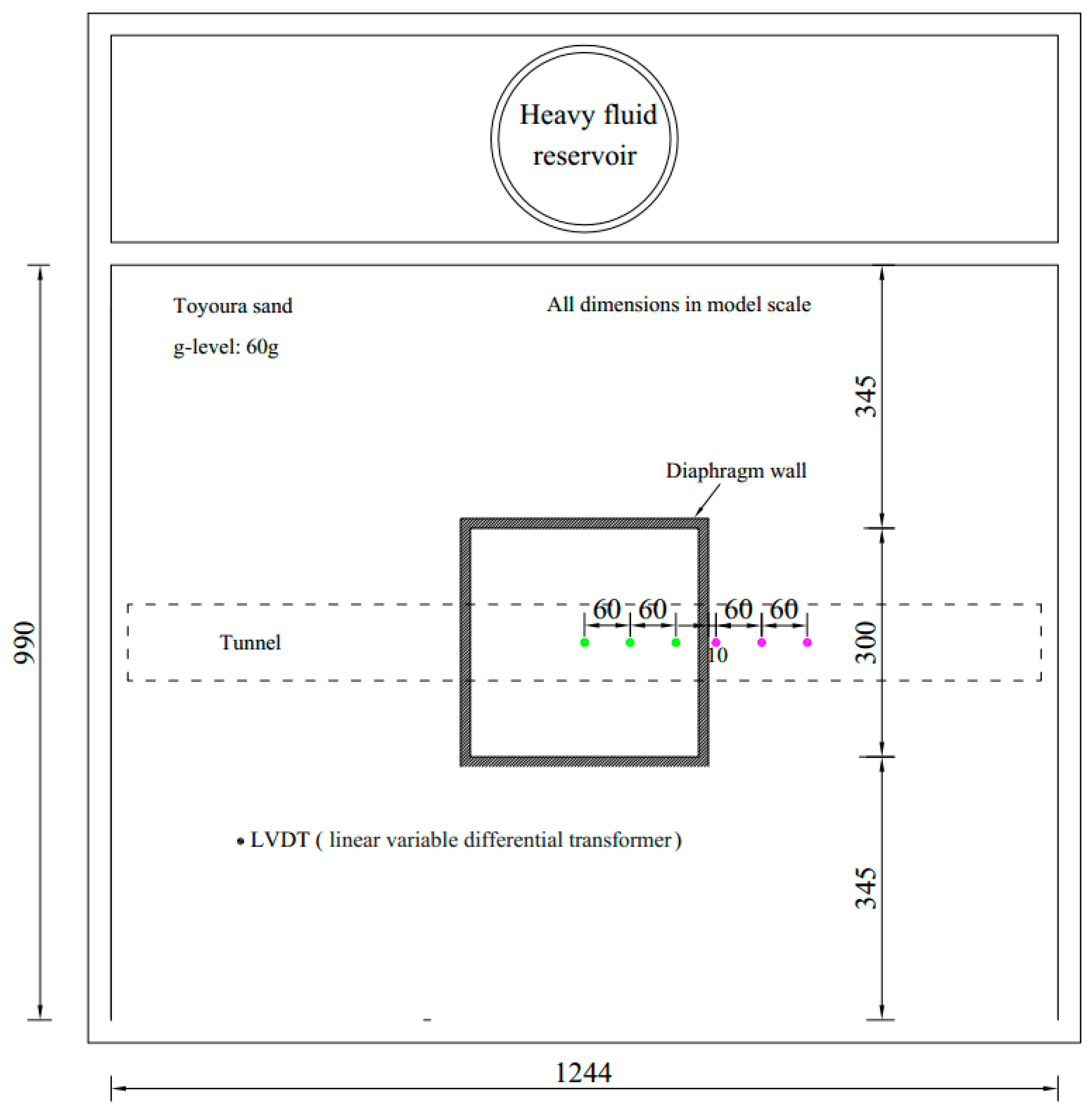
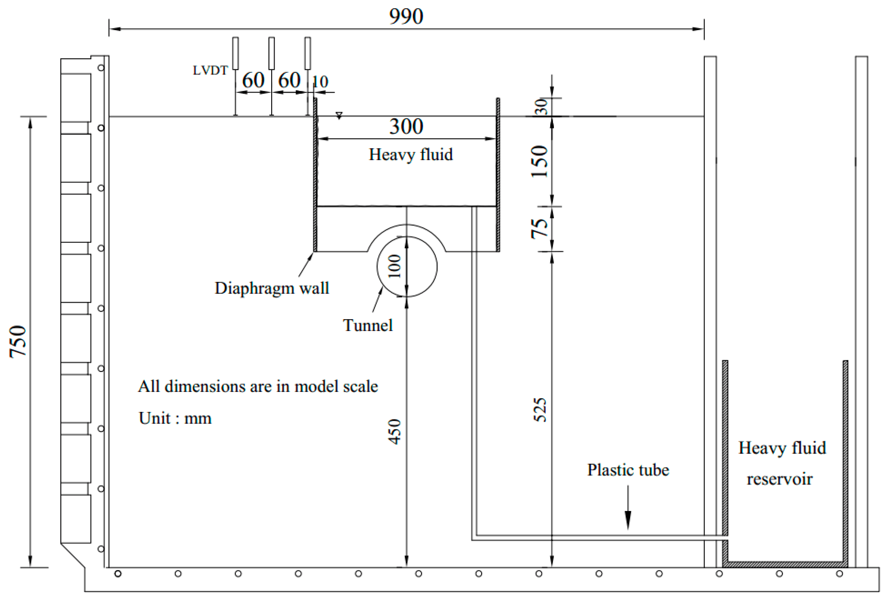
2.1. Description of the Simulated Centrifuge Test

The basis of the numerical simulation was derived from a centrifugal model test conducted by Ng et al. [4]. The tunnel was located just below the center of a pit, as shown in Figure 1 and Figure 2. The centrifuge model test was conducted at the Hong Kong University Science and Technology centrifuge [21,22,23]. The foundation pit excavation was simulated using the discharge-of-heavy-liquid method, and the excavation depth was controlled using a piezometer. The excavation of the basement was carried out in three steps, and each excavation step was 3 m. Details regarding the process of the centrifuge model tests can be found in the report by Ng et al. [4].

2.2. Finite Element Analysis

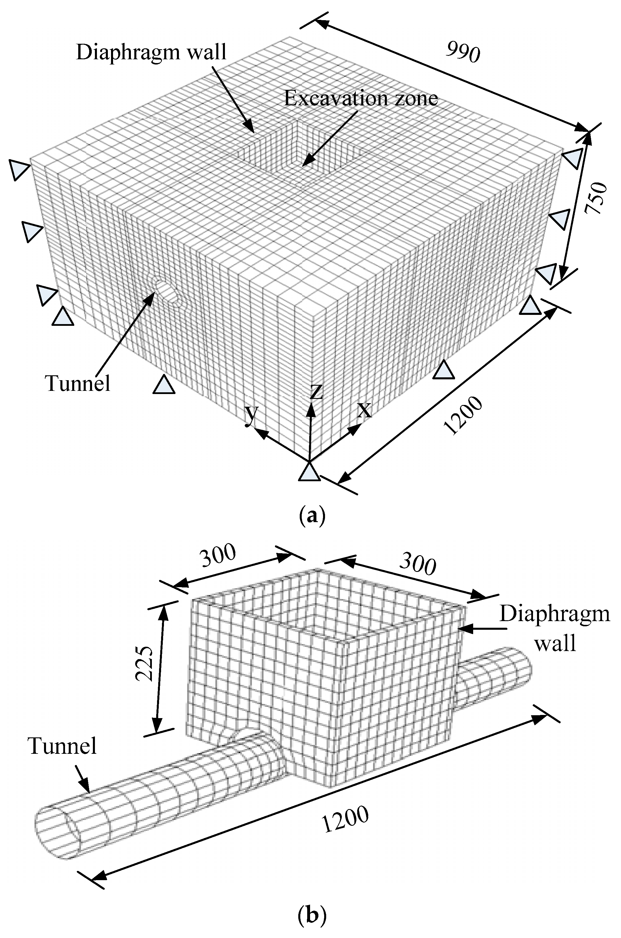
2.2.1. Finite Element Mesh and Boundary Conditions

The finite element program ABAQUS [24] was used to simulate the effect of the basement excavation on the existing tunnel. Figure 3 shows the three-dimensional finite element mesh adopted in the analysis. The mesh dimensions were 1200 mm in length, 990 mm in width, and 750 mm in depth. An eight-node brick element was used to simulate the sand and the diaphragm wall, and a four-node shell element was used to simulate the tunnel. Pin supports were applied to all vertical sides and the base of the mesh to restrain movement in any direction (x-, y- or z-direction).
In all numerical analyses, interface elements were used at the soil–tunnel and soil–basement wall interfaces, unless otherwise specified. Each interface element was a zero-thickness slip element governed by the Coulomb friction law. The friction coefficient (µ) and limiting relative displacement (γlim), where the slippage occurred, were controlled by two input parameters for each slip element. The interface friction coefficient µ was derived from μ = tan δ , where δ is the interface friction angle, which was taken as 20° (i.e., 2/3 of the soil’s critical friction angle). The limiting displacement of 5 mm was assumed to achieve the full mobilization of the interface friction.

2.2.2. Constitutive Model and Model Parameters

In the experiment, the tunnel and diaphragm wall were made of aluminum alloy and considered elastic materials in the numerical analyses. The Young’s modulus and Poisson’s ratio of the aluminum alloy were 70 GPa and 0.2, respectively. The sand was simulated using the Mohr–Coulomb model as a first-order model based on the comparison reported by Ng et al. [14]. To describe the mechanical behavior of the soil in this model, five parameters are needed: Young’s modulus E, Poisson’s ratio ν, friction angle φ, cohesion c, and dilatancy angle ψ. The chosen parameters are listed in Table 1. The parameter selection process and parameter values have been reported by Ng et al. [14].

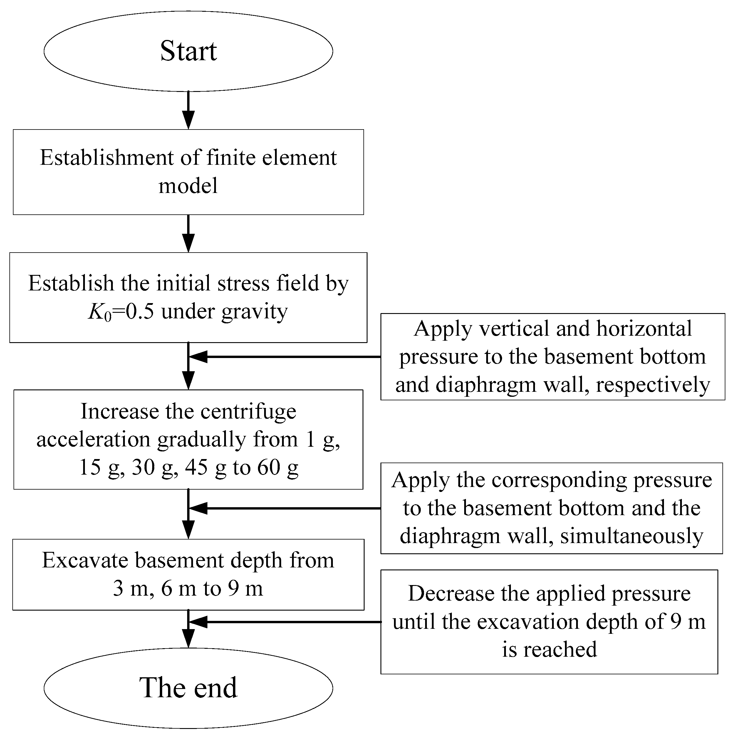
2.2.3. Numerical Modeling Procedure

The numerical modeling procedure is summarized as follows and shown in Figure 4:
  • Establish the initial stress conditions using K0 = 0.5. Apply the same amount of vertical and horizontal pressure as that in the centrifuge test to the formation level and diaphragm wall, respectively.
  • Increment the gravitational acceleration of the entire model from 1 g to 60 g. Simultaneously, apply pressure to the formation level and wall.
  • Decrease the amount of vertical and horizontal pressure gradually in each excavation stage to simulate excavation up to a depth of 9 m.

2.2.4. Numerical Modeling Scheme

It should be noted that there is no ground reinforcement in the centrifuge model test. However, the numerical modeling schemes include the cases with and without ground reinforcement. The centrifuge tests provide a benchmark for verifying the correctness and reasonability of the numerical results with no reinforcement. Furthermore, testing of the effect of the reinforcement on tunnel response due to stress relief can be conducted. The ground is assumed to be reinforced by grouting. All parameters of the ground mechanical behavior change after reinforcement may affect tunnel response. A parametric study was conducted to investigate the effect of soil friction angle, cohesion, etc., on the tunnel response. It was found that the strength indexes had only a little influence on tunnel deformation. However, the Young’s modulus may play an important role in predicting the tunnel response. Thus, this study focused on the study of the soil’s Young’s modulus. Figure 5 shows the schematic diagram of the basement bottom reinforcement. The soil mass between the basement bottom and the tunnel was divided into parts 1, 2, and 3, with each part being 10 mm in the model (0.6 m in the prototype). Note that reinforcement S1 was equal to area 1, S2 was equal to area 1 plus area 2, and S3 was the sum of areas 1, 2, and 3. In the first scheme, the effect of the reinforced area’s Young’s modulus on the behavior of the tunnel was investigated, assuming that the reinforcement area underneath the basement was S1. The reinforced soil’s Young’s modulus varied between 1, 5, and 10 times the value of the soil’s initial Young’s modulus. As for the 5-times and 10-times values, they may not be close to reality but are certainly helpful for practice engineers to judge the effect of soil Young’s modulus on the tunnel response. In the second scheme, the Young’s modulus of the reinforced soil was constant (Er = 5Es), and the effect of the reinforcement depth on the tunnel’s behavior was investigated. The reinforcement depth varied from area S1 = 0.6 m and S2 = 1.2 m to S3 = 1.8 m in the prototype.

3. Results and Analysis

3.1. Effect of Reinforced Soil’s Young’s Modulus on Tunnel Heave

Figure 6 shows the comparison of the measured and computed normalized tunnel heave and maximum tunnel heave variation with different soil reinforcement moduli, where He is the final excavation depth. As can be seen in Figure 6a, the computed values were generally in agreement with the measured data reported by Ng et al. (2013) [4]. The difference between the measurements and the simulation results may be due to the chosen constitutive model. The adopted elastic–plasticity model with Mohr–Coulomb criterion could not capture the strain- and path-dependent soil stiffness. The maximum tunnel heave occurred at the tunnel crown underneath the basement center and decreased gradually as the distance away from the center of the basement increased.
According to the Land Transport Authority of Singapore [25], the maximum tunnel movement should not exceed 15 mm (i.e., 0.17% He). When none of the soil elements were reinforced, the computed maximum tunnel heave was 0.116% He, which overestimated the measured tunnel heave by 50%. In this study, both the computed and measured maximum tunnel heave were within the recommended allowable limit. Because the soil area S1 was reinforced with a Young’s modulus that varied between Es and 5Es, the computed tunnel heave decreased greatly from 0.116% He to 0.095% He, which overestimated the tunnel heave by 32%. However, the measured tunnel heave was overestimated by 23% as the reinforced soil’s Young’s modulus increased to 10Es. Thus, it is obvious that soil reinforcement underneath the basement reduced the tunnel heave. Further increase of the reinforcement’s Young’s modulus reduced the tunnel heave, but with a decreasing tendency. For comparison, the overestimated maximum tunnel heave is listed in Table 2. The basic value is the result obtained from the centrifuge model test.

3.2. Effect of Reinforced Soil’s Young’s Modulus on Tunnel Diameter Change

Figure 7 shows the measured and computed change in the tunnel diameter with different soil reinforcement moduli. The positive and negative values denote the elongation and compression of the tunnel, respectively. It is noted that the described tunnel deformation was located in the tunnel section in a circumferential direction. All three cases predicted that the tunnel lining was vertically elongated and horizontally compressed and that the magnitude of the elongation (ΔDV) and compression (ΔDH) increased with the excavation depth. All of the computed values underestimated the tunnel diameter change in comparison to the experimental measurements. This can be attributed to the fact that, in the transverse direction, the computed soil stiffness around the tunnel was larger than that in the centrifuge model test. According to the British Tunnelling Society [26], the maximum distortion of a tunnel ( ( Δ D V + Δ D H ) / D ) should not exceed 2%. The maximum distortion of the existing tunnel (i.e., 0.09% D), which was induced by the basement excavation in this study, was within the abovementioned allowable limit. The increase of the reinforced soil’s Young’s modulus varied from Es to 5Es, which led to the maximum elongation of the tunnel lining of 9%. Significant changes were not observed when the reinforced soil’s Young’s modulus increased from 5Es to 10Es. Thus, it was concluded that only a slight influence was exerted by the reinforced soil’s Young’s modulus on the change of the tunnel diameter.

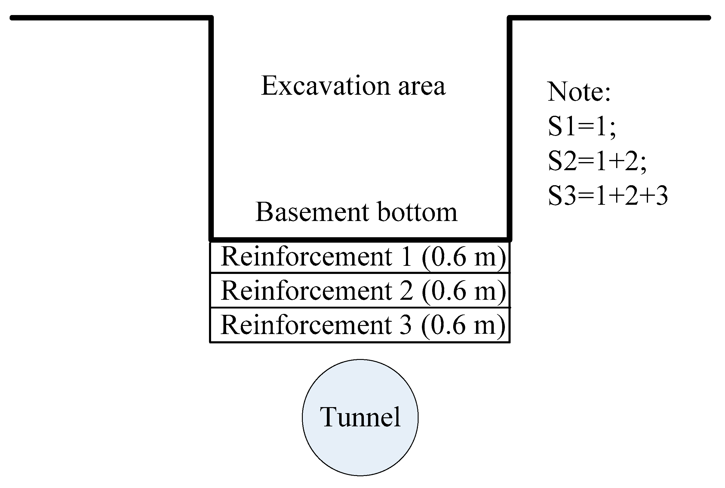
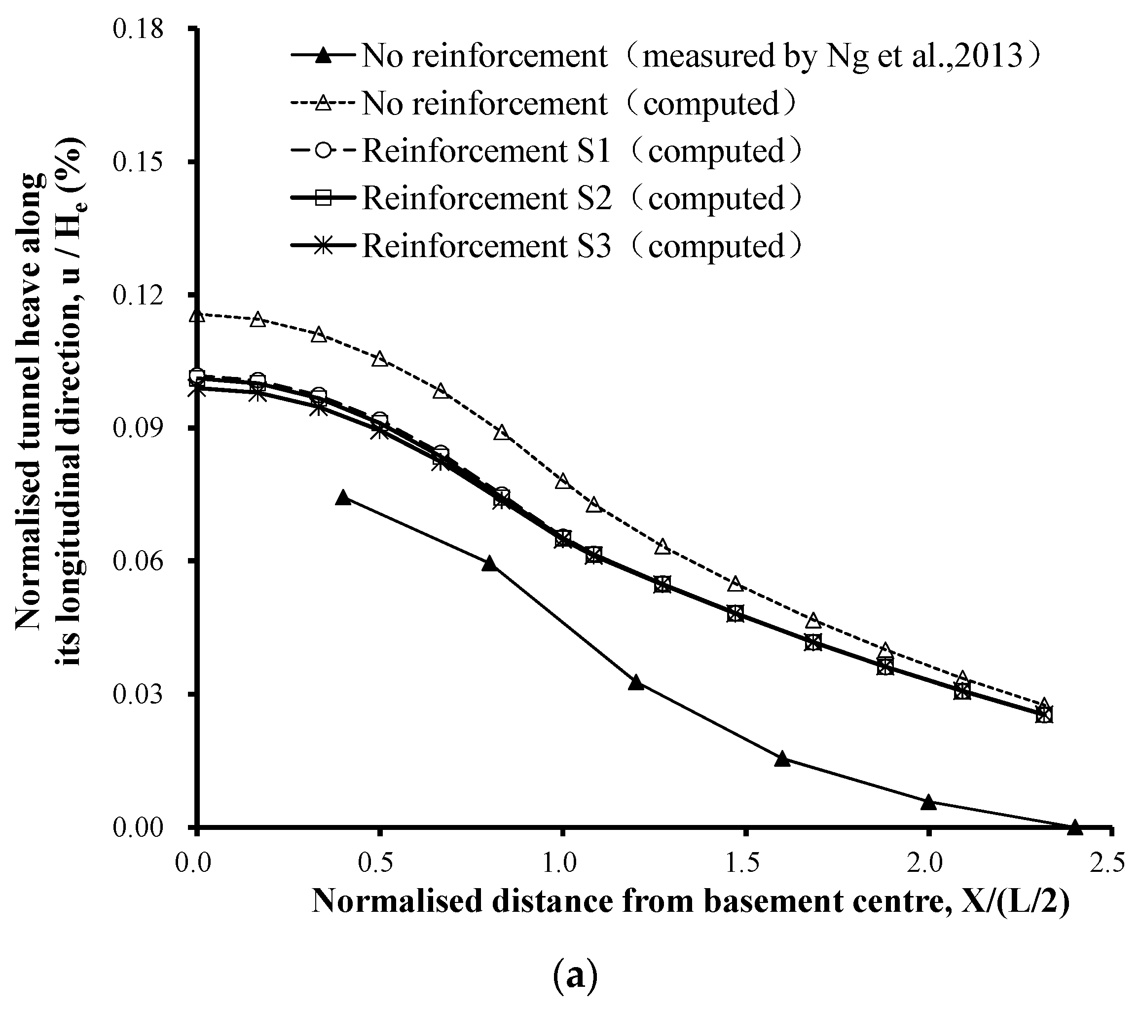
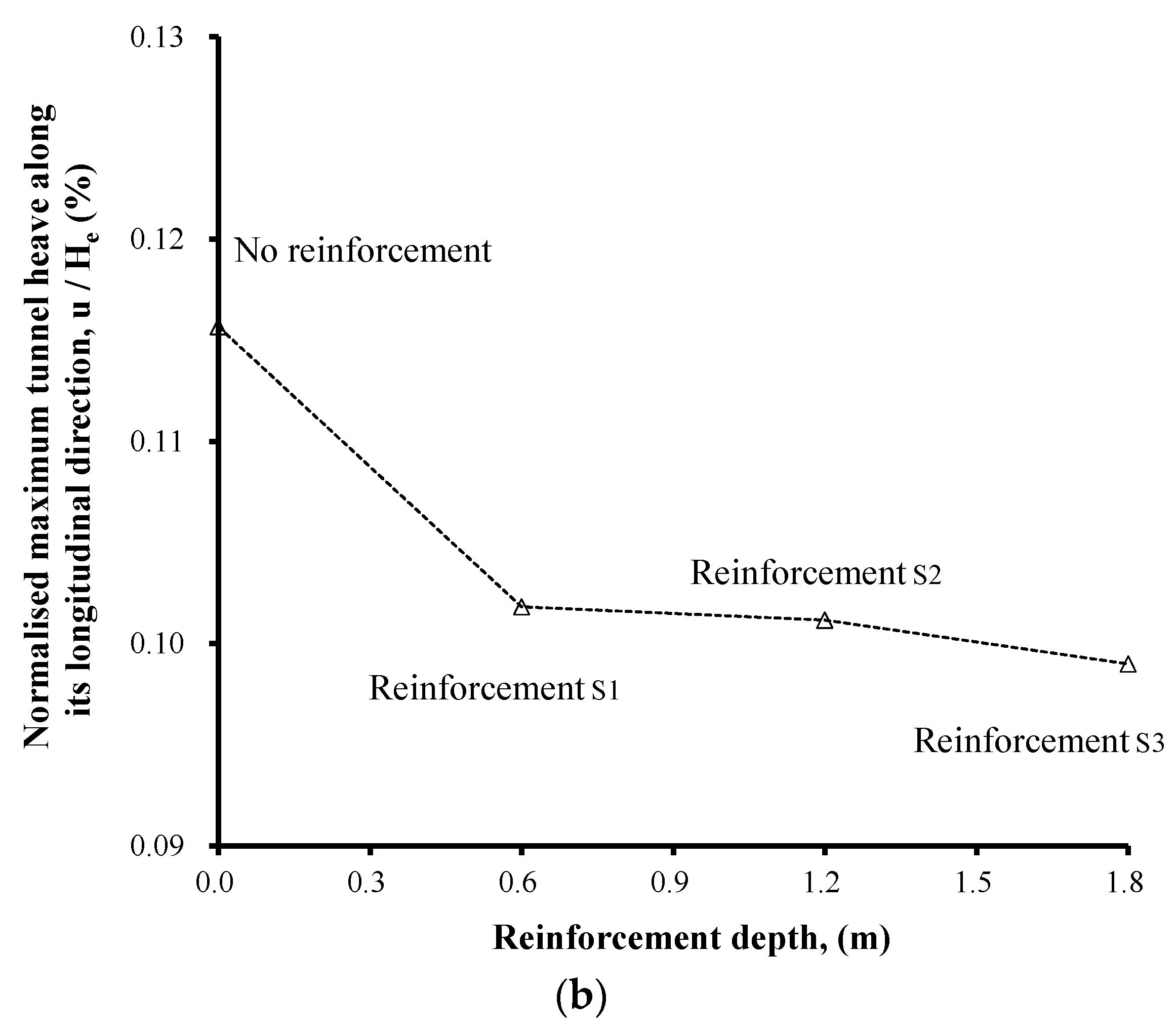
3.3. Effect of Reinforcement Depth on Tunnel Heave

Figure 8 compares the measured and computed normalized tunnel heave and maximum tunnel heave variation with different reinforcement depths, where He is the final excavation depth. When none of the soil elements were reinforced, the computed maximum tunnel heave was 0.116% He. When the soil area S1 was reinforced, the computed tunnel heave decreased from 0.116% He to 0.099% He with a constant reinforcement Young’s modulus. However, significant changes were not observed when the reinforcement depth increased further. Thus, it is obvious that the soil reinforcement depth underneath the basement reduced the tunnel heave, even for a thin layer. The further increase of the reinforcement depth did not have an effect and was uneconomical.

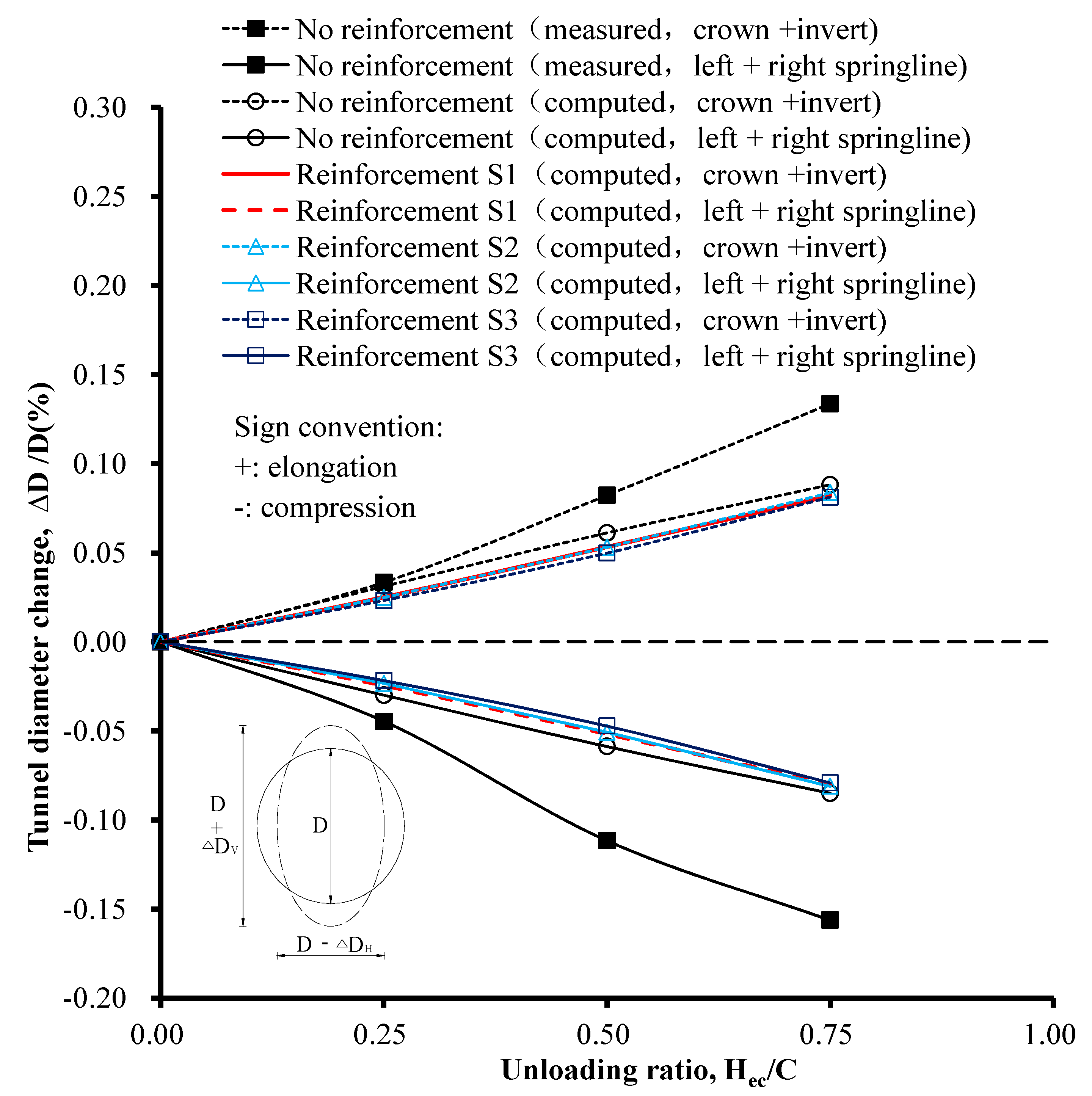
3.4. Effect of Reinforcement Depth on Tunnel Diameter Change

Figure 9 shows the measured and computed changes in the tunnel diameter with different soil reinforcement depths. The positive and negative values denote the elongation and compression of the tunnel, respectively. It is also noted that the described tunnel deformation was located in the tunnel section in a circumferential direction. Tunnel diameter was elongated in the vertical direction and compressed in the horizontal direction after stress relief. The elongated and compressed values increased with the unloading ratio. As the reinforcement depth increased, the elongation and compression of the tunnel lining decreased. Obvious changes were not observed when the reinforcement depth increased further. Thus, it was concluded that the reinforcement depth exerted only a slight influence on the change of the tunnel diameter. When the unloading ratio was 0.5 and the soil area S3 was reinforced, the tunnel diameter change was 0.061%. Compared with the 0.049% change for no reinforcement, a maximum tunnel diameter change ratio of 19% occurred. A summary of the comparison between the computed and measured values is presented in Table 2.

3.5. Analyses of Soil Responses Caused by Excavation

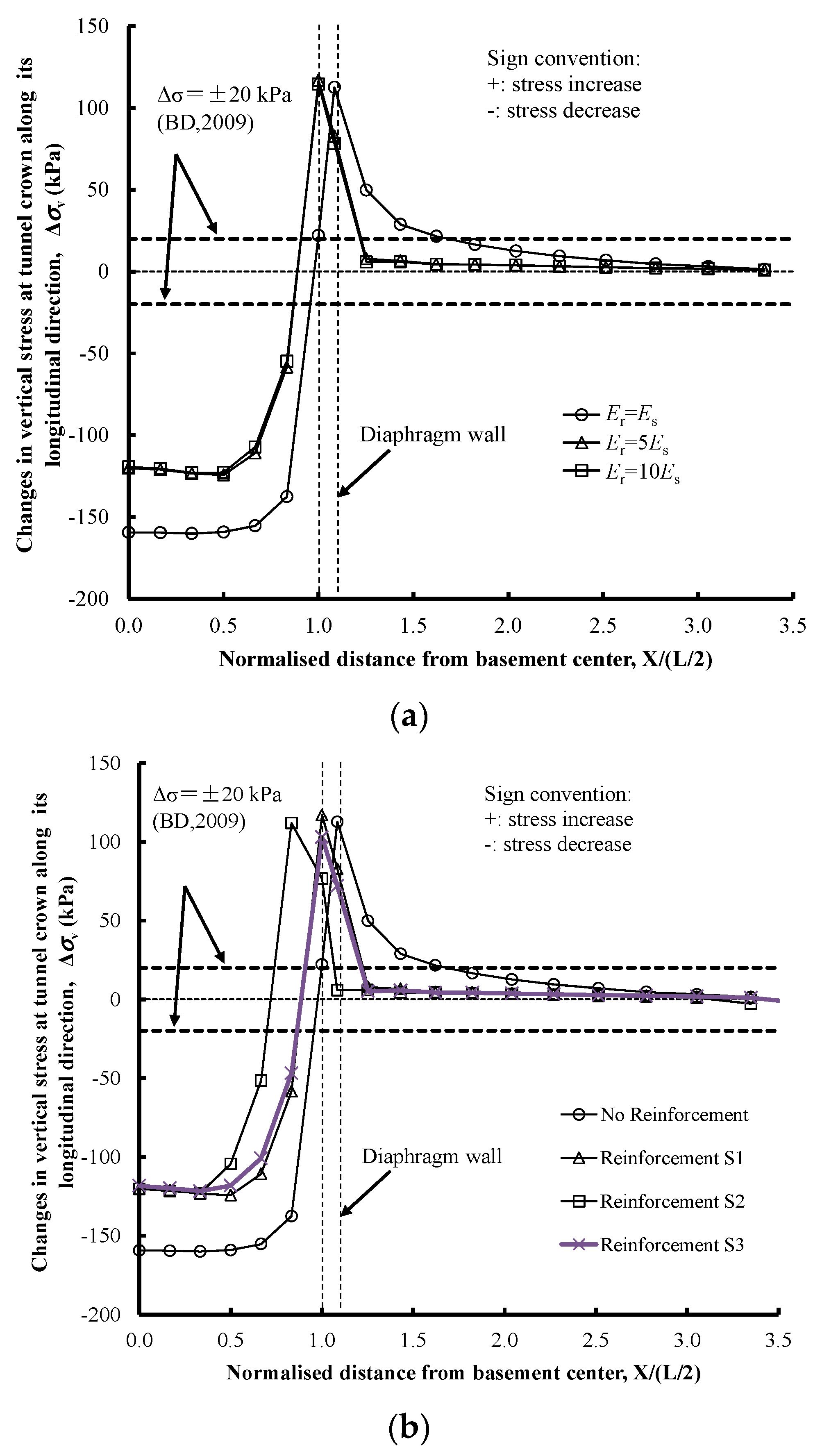
3.5.1. Stress Distributions of Soil Elements in the Tunnel’s Longitudinal Direction

To better understand the tunnel behavior in the transverse and longitudinal directions, the stress distribution of the soil elements around the tunnel are presented in Figure 10 and Figure 11. Figure 10a shows the computed changes in the vertical stress at the tunnel crown in the longitudinal direction for different reinforcement Young’s moduli. The positive and negative values denote the increase and decrease in the stress acting on the tunnel lining, respectively. Along the tunnel crown, the vertical stress beneath the basement reduced significantly as a result of the excavation. An almost uniform stress relief was observed beneath the basement. The stress was concentrated beneath the diaphragm wall. This is because the tunnel moved upward due to stress relief, whereas the trend was blocked by the diaphragm wall. The concentrated stress may increase largely beneath the diaphragm wall and then dissipate behind the wall. Thus, it is possible that there will be an increase in stress, which has also been observed in the literature [14]. The vertical stress in the soil increased by more than 100 kPa. After the basement excavation, the maximum change in the vertical stress at the tunnel crown exceeded the allowable limit (i.e., ±20 kPa) set by the Building Department of Hong Kong [27]. In the case where the soil element was not reinforced, the maximum reduction in the vertical stress was 159 kPa. When the reinforced soil’s Young’s modulus increased from Es to 5Es, the maximum reduction in the vertical stress was 120 kPa. This was because the reinforced soil blocked the stress transfer and thus reduced the stress release around the tunnel. However, obvious stress changes were not observed when the reinforced soil’s Young’s modulus increased from 5Es to 10Es, which can explain the phenomenon shown in Figure 6. Figure 10b shows the computed changes in the vertical stress at the tunnel crown in the longitudinal direction for different reinforcement depths. As can be seen, the maximum stress reduction was restrained from 159 kPa to 120 kPa when the reinforcement depth changed from 0 to 0.6 m. Further obvious changes were not observed for a reinforcement depth larger than 0.6 m, which is consistent with the tunnel heave change shown in Figure 8.

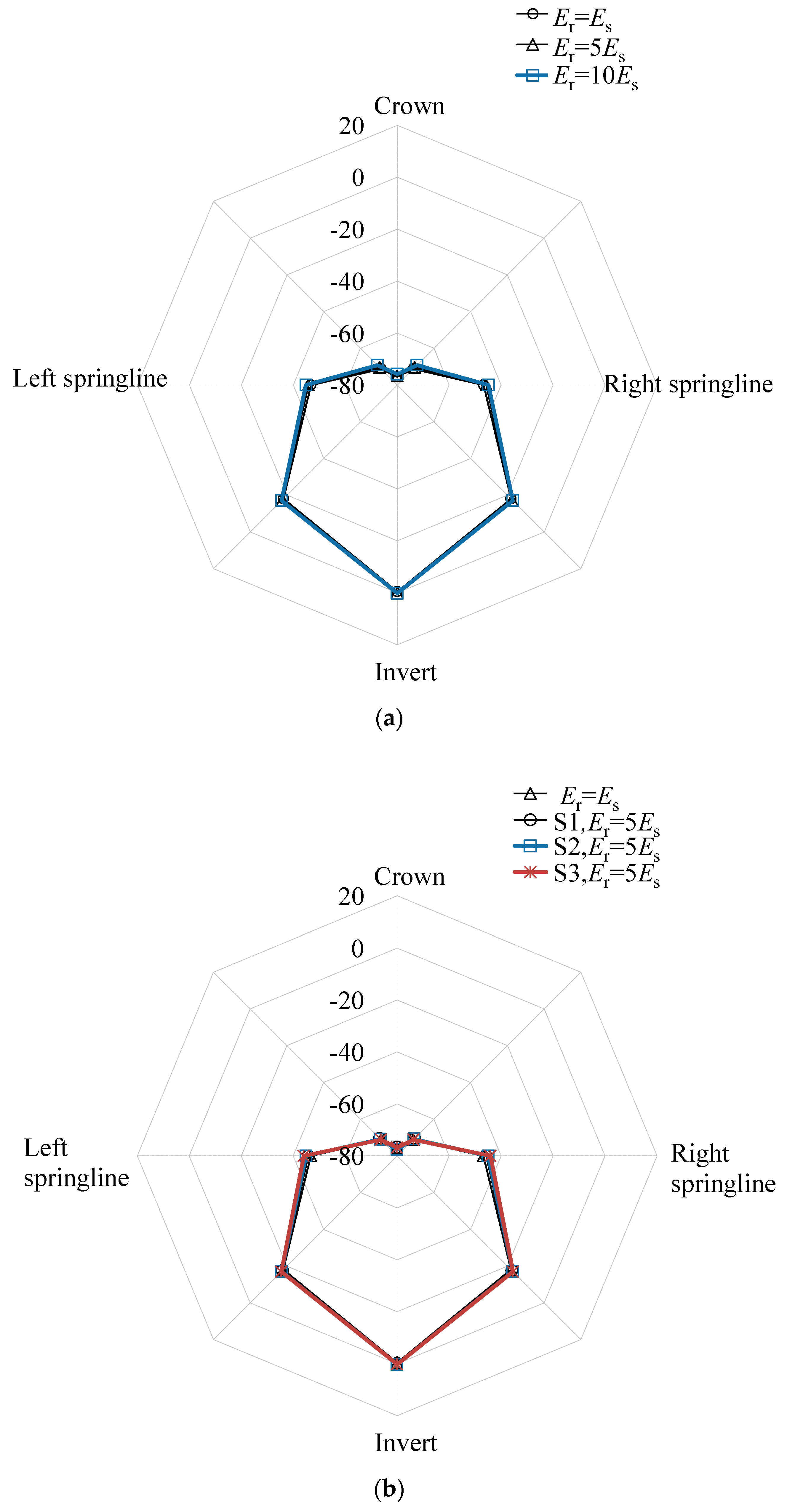
3.5.2. Stress Distributions of Soil Elements in the Tunnel’s Transverse Direction

Figure 11 shows the normal stress change distribution of the soil elements in the transverse direction of the tunnel which was located in the section under the center of the basement. As can be seen, the maximum and minimum stress changes were 80 kPa and almost 0 kPa, respectively, and occurred at the top of the tunnel and at the invert, respectively. It was found that the stress at the invert changed little. This may be due to the rather large stiffness of the tunnel which prevented the stress change of the soil at the tunnel invert. The stress change in the soil elements around the tunnel springlines was 45 kPa. Thus, the tunnel circumference was elongated in the vertical direction and compressed in the horizontal direction, as shown in Figure 7 and Figure 9. As can be seen in Figure 10, in all reinforced cases, only a slight stress change could be observed for the soil elements around the tunnel, in comparison to the non-reinforced case. This can be explained by the diameter change, as shown in Figure 7 and Figure 9.

4. Conclusions

This study evaluated the effect of the reinforced soil’s Young’s modulus and the effect of the reinforcement depth on the tunnel response as a result of a basement excavation, based on back-analyzing a centrifuge model test with no reinforcement. The tunnel heave and diameter change and the stress changes both in the longitudinal and in the transverse directions, were analyzed. The obtained results can provide reference for practical engineering in terms of applying construction measures to control tunnel deformation caused by stress relief. Based on the above analyses, the following conclusions were drawn:
(a)
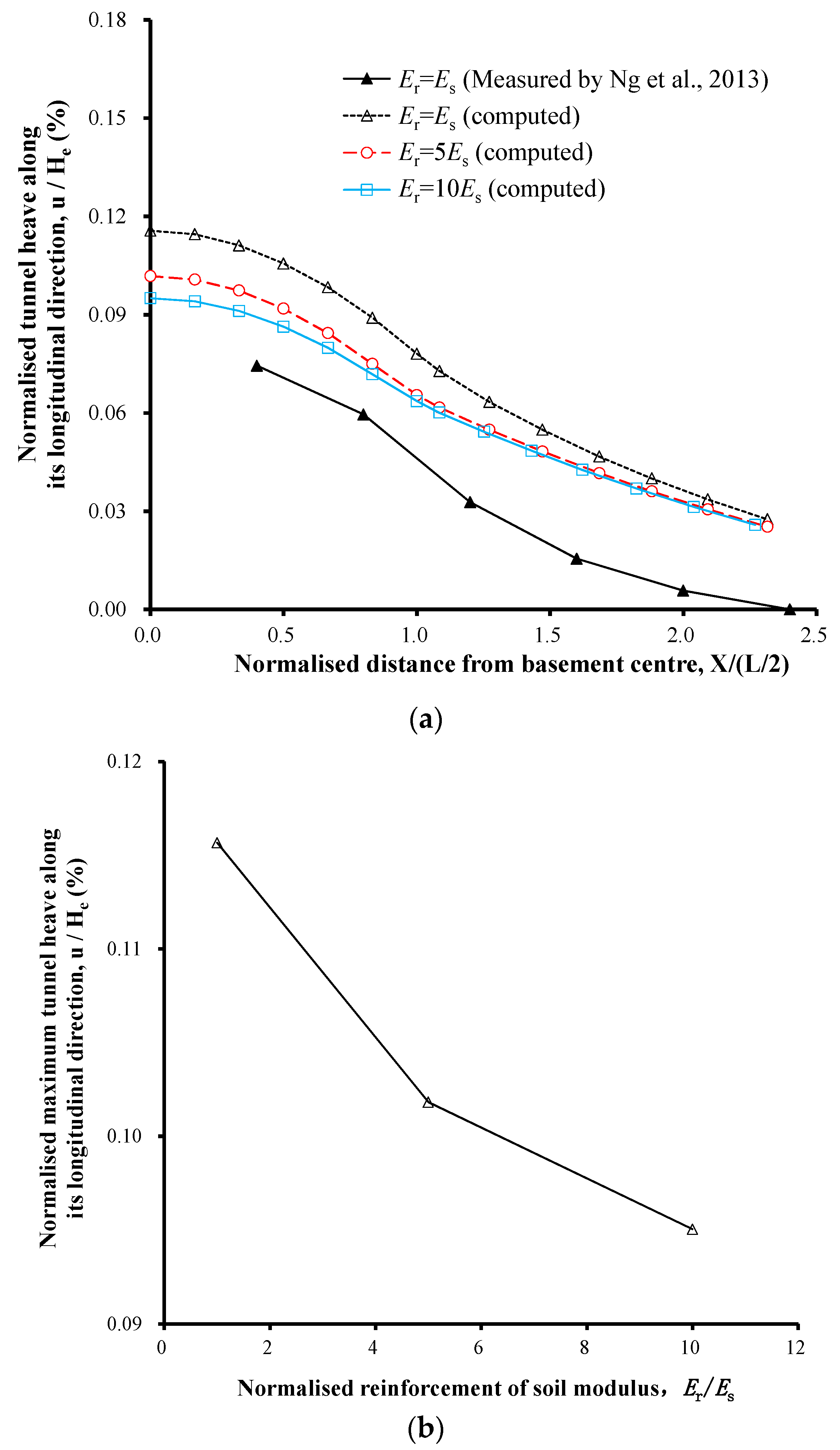
As a result of the stress relief caused by the basement excavation, tunnel heave was observed for the tunnel underneath the basement excavation. The heave was greatly reduced by improving the basement bottom soil’s Young’s modulus. When a specific soil area S1 was reinforced with a Young’s modulus that varied from Es to 5Es, the computed tunnel heave decreased by 18%. This was because the reinforced soil blocked the stress transfer and thus reduced the tunnel heave caused by excavation unloading. A further increase of the reinforced soil’s Young’s modulus did not significantly reduce the tunnel heave. This can be attributed to the fact that obvious stress changes were not observed when the reinforced soil’s Young’s modulus increased from 5Es to 10Es.
(b)
When the reinforcement depth was 0.6 m, the computed tunnel heave decreased by 15% in comparison with the non-reinforced case. However, significant changes were not observed when the reinforcement depth increased further. The further increase of reinforcement depth had no effect and would therefore be uneconomical.
(c)
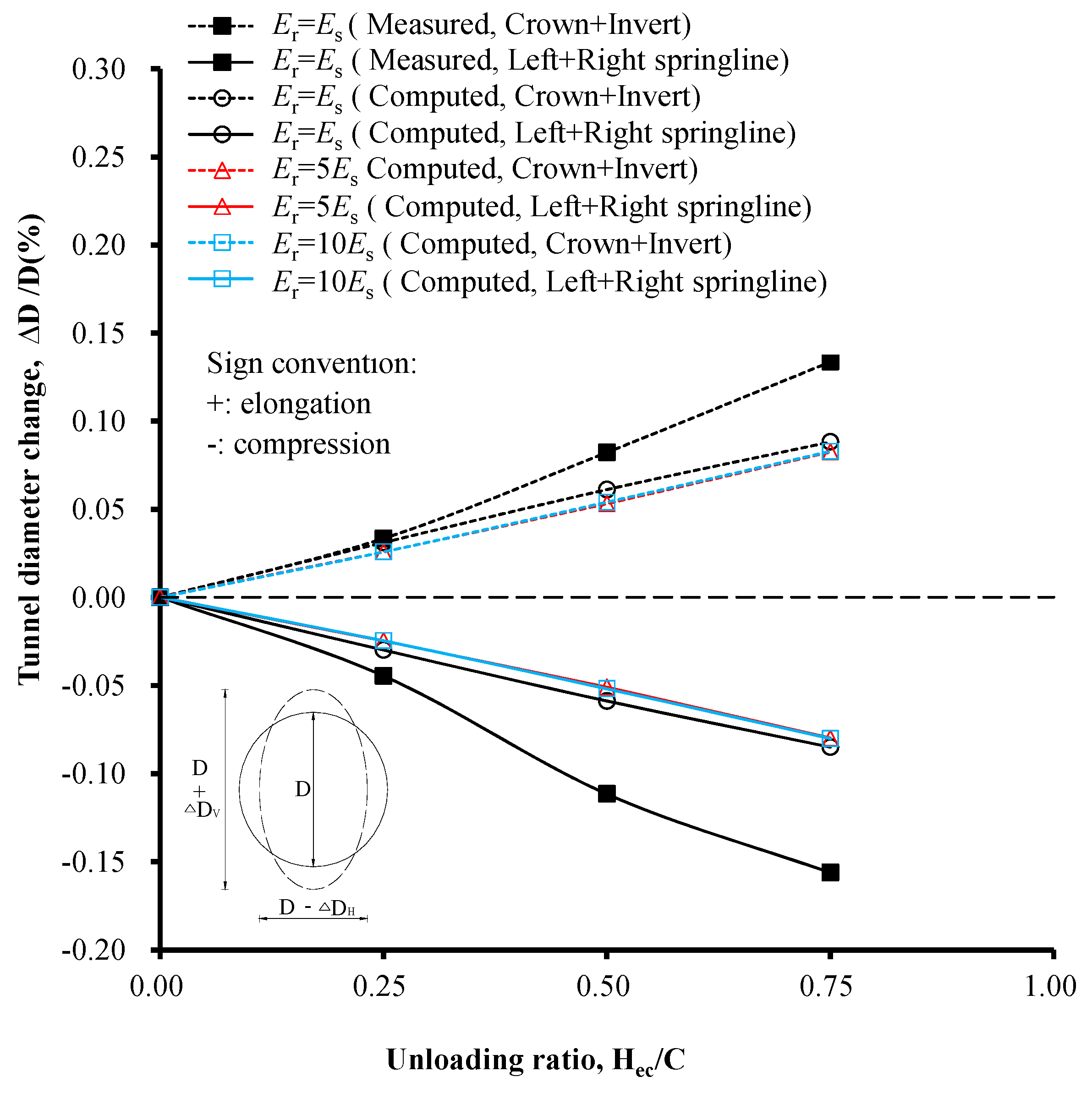
As the reinforced soil’s Young’s modulus varied from Es to 5Es, the maximum elongation of the tunnel lining in the circumferential direction changed by 9%. Significant changes were not observed when the reinforced soil’s Young’s modulus increased from 5Es to 10Es. Significant changes were not observed when the reinforcement depth increased further. Thus, it was concluded that the reinforced soil’s Young’s modulus and the reinforcement depth exerted only a slight influence on the diameter change of the tunnel.

Author Contributions

Conceptualization, H.S.; methodology, H.S.; software, H.S.; validation, W.S.; formal analysis, H.S. and W.S.; investigation, H.S. and W.S.; resources, W.S.; data curation, H.S.; writing—original draft preparation, H.S.; writing—review and editing, H.S. and W.S.; visualization, H.S.; supervision, H.S.; project administration, H.S.; funding acquisition, H.S.

Funding

This study was sponsored by the National Natural Science Foundation of China (grant number 51708245), the Natural Science Foundation of Jiangsu Province (grant number BK20160426), the Construction System Science and Technology Project of Jiangsu Province (grant number 2017ZD124), the Natural Science Foundation for Colleges and Universities in Jiangsu Province (17KJB130003, 17KJA560001), the Project with Science and Technology of Huai’an City (HAG201606).

Acknowledgments

We thank Liwen Bianji, Edanz Editing China (www.liwenbianji.cn/ac) for editing the English text of a draft of this manuscript.

Conflicts of Interest

The authors declare that there is no conflict of interest regarding the publication of this paper.

Data Availability Statement

The computed data used to support the findings of this study are included within the article. Previously reported measured data were used to support this study and are available at [https://doi.org/10.1139/cgj-2012-0423, https://doi.org/10.1139/cgj-2014-0361]. These prior studies (and datasets) are cited at relevant places within the text as references [4,14].

References

  1. Burford, D. Heave of tunnels beneath the Shell Centre. London, 1959–1986. Géotechnique 1988, 38, 135–137. [Google Scholar] [CrossRef]
  2. Chang, C.-T.; Sun, C.-W.; Duann, S.; Hwang, R.N. Response of a Taipei Rapid Transit System (TRTS) tunnel to adjacent excavation. Tunn. Undergr. Space Technol. 2001, 16, 151–158. [Google Scholar] [CrossRef] [Green Version]
  3. Simpson, B.; Vardanega, P.J. Results of monitoring at the British Library excavation. Proc. Inst. Civ. Eng.—Geotech. Eng. 2014, 167, 99–116. [Google Scholar] [CrossRef] [Green Version]
  4. Ng, C.W.; Shi, J.; Hong, Y. Three-dimensional centrifuge modelling of basement excavation effects on an existing tunnel in dry sand. Can. Geotech. J. 2013, 50, 874–888. [Google Scholar] [CrossRef]
  5. Huang, H.; Huang, X.; Zhang, D. Centrifuge modelling of deep excavation over existing tunnels. Proc. Inst. Civ. Eng.—Geotech. Eng. 2014, 167, 3–18. [Google Scholar] [CrossRef]
  6. Ng, C.; Shi, J.; Lei, G.; Mašín, D.; Sun, H. Influence of sand density and retaining wall stiffness on three-dimensional responses of tunnel to basement excavation. Can. Geotech. J. 2015, 52, 1811–1829. [Google Scholar] [CrossRef]
  7. Lo, K.; Ramsay, J. The effect of construction on existing subway tunnels—A case study from Toronto. Tunn. Undergr. Space Technol. 1991, 6, 287–297. [Google Scholar] [CrossRef]
  8. Doležalová, M. Tunnel complex unloaded by a deep excavation. Comput. Geotech. 2001, 28, 469–493. [Google Scholar] [CrossRef]
  9. Sharma, J.S.; Hefny, A.M.; Zhao, J.; Chan, C.W. Effect of large excavation on displacement of adjacent MRT tunnels. Tunn. Undergr. Space Technol. 2001, 16, 93–98. [Google Scholar] [CrossRef]
  10. Hu, Z.F.; Yue, Z.Q.; Zhou, J.; Tham, L.G. Design and construction of a deep excavation in soft clay adjacent to the shanghai metro tunnels. Can. Geotech. J. 2003, 40, 933–948. [Google Scholar] [CrossRef]
  11. Zheng, G.; Wei, S.W. Numerical analysis of influence of overlying pit excavation on existing tunnels. J. Cent. South Univ. Technol. 2008, 15, 69–75. [Google Scholar] [CrossRef]
  12. Liu, H.L.; Li, P.; Liu, J.Y. Numerical investigation of underlying tunnel heave during a new tunnel construction. Tunn. Undergr. Space Technol. 2011, 26, 276–283. [Google Scholar] [CrossRef]
  13. Huang, X.; Schweiger, H.F.; Huang, H.W. Influence of deep excavations on nearby existing tunnels. Int. J. Geomech. ASCE 2013, 13, 170–180. [Google Scholar] [CrossRef]
  14. Ng, C.W.W.; Sun, H.S.; Lei, G.H.; Shi, J.W.; Mašín, D. Ability of three different soil constitutive models to predict a tunnel’s response to basement excavation. Can. Geotech. J. 2015, 52, 1685–1698. [Google Scholar] [CrossRef]
  15. Shi, J.; Ng, C.W.W.; Chen, Y. Three-dimensional numerical parametric study of the influence of basement excavation on existing tunnel. Comput. Geotech. 2015, 63, 146–158. [Google Scholar] [CrossRef]
  16. Zhang, J.F.; Chen, J.J.; Wang, J.H.; Zhu, Y.F. Prediction of tunnel displacement induced by adjacent excavation in soft soil. Tunn. Undergr. Space Technol. 2013, 36, 24–33. [Google Scholar] [CrossRef]
  17. Zhang, Z.; Huang, M.; Wang, W. Evaluation of deformation response for adjacent tunnels due to soil unloading in excavation engineering. Tunn. Undergr. Space Technol. 2013, 38, 244–253. [Google Scholar] [CrossRef]
  18. Zhang, Z.; Zhang, M.; Zhao, Q. A simplified analysis for deformation behavior of buried pipelines considering disturbance effects of underground excavation in soft clays. Arab. J. Geosci. 2015, 8, 1–15. [Google Scholar] [CrossRef]
  19. Liang, R.; Wu, W.; Yu, F. Simplified method for evaluating shield tunnel deformation due to adjacent excavation. Tunn. Undergr. Space Technol. 2018, 71, 94–105. [Google Scholar] [CrossRef]
  20. Zheng, G.; Du, Y.M.; Diao, Y. Influenced zones for deformation of existing tunnels adjacent to excavations. Chin. J. Geotech. Eng. 2016, 38, 599–612. [Google Scholar]
  21. Ng, C.W.W.; Van Laak, P.A.; Tang, W.H.; Li, X.S.; Zhang, L.M. The Hong Kong geotechnical centrifuge. In Proceedings of the 3rd International Conference on Soft Soil Engineering, Hong Kong, China, 6–8 December 2001; pp. 225–230. [Google Scholar]
  22. Ng, C.W.W.; Van Laak, P.A.; Zhang, L.M.; Tang, W.H.; Zong, G.H.; Wang, Z.L.; Xu, G.M.; Liu, S.H. Development of a four-axis robotic manipulator for centrifuge modeling at HKUST. In Proceedings of the International Conference on Physical Modelling in Geotechnics, St John’s, NL, Canada, 10–12 July 2002; pp. 71–76. [Google Scholar]
  23. Ng, C.W.W. The state-of-the-art centrifuge modelling of geotechnical problems at hkust. J. Zhejiang Univ. A 2014, 15, 1–21. [Google Scholar] [CrossRef]
  24. ABAQUS, Inc. ABAQUS User’s and Theory Manuals; Version 6.17; ABAQUS, Inc.: Providence Rhode Island, RI, USA, 2017. [Google Scholar]
  25. LTA. Code of Practice for Railway Protection; Development & Building Control Department, Land Transport Authority (LTA): Singapore, 2000.
  26. BTS. Specification for Tunnelling; British Tunnelling Society (BTS): Thomas Telford, London, UK, 2000. [Google Scholar]
  27. BD. Practice Note for Authorized Persons APP-24. Technical Notes for Guidance in Assessing the Effects of Civil Engineering Construction/Building Development on Railway Structures and Operations; Building Department of the Government of HKSAR (BD): Hongkong, China, 2009.
Figure 1. Plan view of the centrifuge model (redraw from Ng et al., 2013) [4].
Applsci 09 01420 g001
Figure 2. Elevation view of the centrifuge model in model scale (mm) (redraw from Ng et al., 2013) [4].
Applsci 09 01420 g002
Figure 3. (a) Three-dimensional finite element model in model scale (mm) and (b) intersection of tunnel and diaphragm wall.
Applsci 09 01420 g003
Figure 4. A sketch of the modeling procedure.
Applsci 09 01420 g004
Figure 5. Reinforcement scheme for basement bottom.
Applsci 09 01420 g005
Figure 6. Measured and computed (a) tunnel heave and (b) maximum tunnel heave with different reinforced soil Young’s moduli.
Applsci 09 01420 g006
Figure 7. Measured and computed changes in tunnel diameter with different soil reinforcement moduli.
Applsci 09 01420 g007
Figure 8. Measured and computed (a) tunnel heave and (b) maximum tunnel heave with different reinforced soil areas.
Applsci 09 01420 g008aApplsci 09 01420 g008b
Figure 9. Measured and computed change in tunnel diameter with different soil reinforcement areas.
Applsci 09 01420 g009
Figure 10. Computed vertical stress change in the soil element at the crown in the circumferential direction for (a) different reinforcement Young’s moduli and (b) different reinforcement depth.
Applsci 09 01420 g010
Figure 11. Computed earth pressure change in the soil element along the tunnel transverse direction for (a) different reinforcement Young’s moduli and (b) different reinforcement depth.
Applsci 09 01420 g011
Table 1. Soil parameters used in the Mohr–Coulomb model.
Soil ParametersValues
Young’s modulus, Es117 MPa
Poisson’s ratio, ν0.3
Peak friction angle, φp35°
Critical friction angle, φc30°
Cohesion, c2 kPa
Dilatancy angle, ψ
Table 2. Comparison of computed and measured values.
CasesYoung’s Modulus of Reinforced Soil, ErMax. Tunnel Heave Max. Change in Tunnel Diameter
No reinforcementEr = Es+50%−35%
Reinforcement S1Er = 5Es+32%−39%
Reinforcement S1Er = 10Es+23%−39%
Reinforcement S2Er = 5Es+31%−39%
Reinforcement S3Er = 5Es+28%−40%
Note: The −ve sign indicates an underestimation and the +ve sign indicates an overestimation.

