Article

Three-Dimensional Wide-Band Electromagnetic Forward Modelling Using Potential Technique

School of Geoscience and Info-physics, Central South University, Hunan 410083, China
*
Authors to whom correspondence should be addressed.
Appl. Sci. 2019, 9(7), 1328; https://doi.org/10.3390/app9071328
Submission received: 26 January 2019 / Revised: 16 March 2019 / Accepted: 25 March 2019 / Published: 29 March 2019
(This article belongs to the Section Applied Physics General)

Abstract

:
The efficacy of Krylov subspace solvers is strongly dependent on the preconditioner applied to solve the large sparse linear systems of equation for electromagnetic problems. In this study, we present a three-dimensional (3-D) plane wave electromagnetic forward simulation over a broadband frequency range. The Maxwell’s equation is solved in a secondary formulation of the Lorentz gauge coupled-potential technique. A finite-volume scheme is employed for discretizing the system of equations on a structured rectilinear mesh. We employed a block incomplete lower-upper factorization (ILU) preconditioner that is suitable for our potential formulation to enhance the computing time and convergence of the systems of equation by comparing with other preconditioners. Furthermore, we observe their effect on the iterative solvers such as the quasi-minimum residual and bi-conjugate gradient stabilizer. Several applications were used to validate and test the effectiveness of our method. Our scheme shows good agreement with the analytical solution. Notably, from the marine hydrocarbon and the crustal model, the utilisation of the bi-conjugate gradient stabilizer with block ILU preconditioner is the most appropriate. Thus, our approach can be incorporated to optimize the inversion process.

1. Introduction

The effectiveness and accuracy of the electromagnetic (EM) responses in heterogeneous media are vital for exploration and delineation of the geological formation [1]. The significance of the electromagnetic technique in geophysical perspective is the diverse application to a range of geological problems from shallow to deep investigation resulting from the sensitivity of the occurrence of fluids, mineralogy, etc. [2].
Numerical simulation has been a typical scheme for modeling and analyzing three-dimensional electromagnetic data [3]. Additionally, an efficient inversion of the electromagnetic data depends on the forward model algorithm. There are various numerical techniques used to solve the three-dimensional electromagnetic forward problems such as the differential equation (finite difference (FD), finite element (FE), finite volume (FV)) and the Integral equation (IE) method. The integral equation (IE) solutions avoid the discretization of the whole domain because only the anomalous domain is discretized [4,5,6]. As a result, the degree of freedom is minimal. Though, the system of linear equations is compact and dense. Several researchers have improved this method [7,8,9,10]. However, for the differential equation such as the finite difference [11,12,13,14], it has been extensively applied because of the simplicity of the approach [15]. It requires large discretization of the computational domain because it consider both the background and anomalous region. It allows for complex earth modelling. The widespread use of the finite element approach is due to the comprehensive mathematical basis [16,17]. The finite element scheme can be applied to both structured [18,19,20] and unstructured grids [21,22]. The governing differential equation is formulated using the weighted residual. The Finite volume can be utilised on both structured [23] and unstructured form [24]. These unstructured grids are essential for accurate modelling of complex and irregular shaped geometry such as the bathymetry of the earth surface. In addition, the capacity to refine the grid locally in the zone of interest allows an efficient discretization of complex earth model [25,26].
The discretized numerical solution of the Helmholtz equation resulted in continuity loss at low frequency for an iterative solver [27]. we can alleviate this problem using the divergence correction [27,28]. On the other hand, we can implement the potential technique. Several investigation has adopted the use of potentials (magnetic vector A and electric scalar φ ) in 3-D forward simulation to solve specific geo-electromagnetic problems [29,30,31,32]. Reference [33] applied the A - φ disintegration of the electric field using the finite volume method to solve magnetotelluric problems. Reference [22] utilized the nodal based finite element approach of the A - φ decomposition to simulate controlled source electromagnetic (CSEM) problems. The edge-based finite element technique was used to observe the (galvanic and inductive) effect of a controlled source electromagnetic forward model by [21].
The frequently used preconditioners such as incomplete lower-upper factorization (ILU) and Cholesky preconditioners that are nontrivial to adopt are necessary to improve the solution of linear systems [34]. However, such preconditioners are not efficient to some type of linear systems of equation. Thus, an efficient preconditioner is vital for broadband (plane-wave) electromagnetic applications as a result of developing an effective forward solver needed for the inversion routine.
In this study, we present a wide-band plane wave electromagnetic modelling problem solved with finite volume method using potentials. We included the theoretical development in secondary formulation and applied the finite volume discretization. In addition, we describe the concept of the block ILU preconditioner. To verify our approach, we simulate and compared our results with the analytical solution and also further tested the algorithm on two synthetic models. Additionally, different iterative solvers and preconditioners were also conducted to observe the most efficient with the example models.

2. Theory and Methodology

2.1. Formulation of Maxwell’s Equations in the Secondary Field

Considering Maxwell’s equations for geophysical application in the quasi-static frequency domain, we have
× E = i μ o ω H
× H = J
where the time dependence is e i ω t , E is the electric field, μ o indicates the magnetic permeability in the free space, ω denotes the angular frequency, H represents the magnetic field, J = σ E which signifies the current density, and σ implies the conductivity [35]. By applying the curl to Equation (1) and substituting Equation (2), one can obtain the second derivative equation for the total E field. In addition, we can partition the total field into the primary and secondary fields [36]. The secondary fields satisfy
× × E s i μ o ω σ E s = i μ o ω Δ σ E p   in   Ω
Here, E p and E s are the primary and secondary electric fields respectively. the (complex valued) conductivity can be expressed as σ = Δ σ + σ b with Δ σ = σ σ b , σ b is the known background conductivity and Ω indicates the computed domain. For the Equation (3), the primary field are computed for a layered background conductivity model. We can decompose the magnetic induction ( B ) field and the electric field ( E ) as
B = × A
E = i ω ( A + φ )
where, A is the magnetic vector potential and φ denotes the electric scalar potential. By implementing the formulation in terms of secondary potentials, the curl–curl Equation (3) can be expressed in terms of the primary potentials ( A p , φ p ) and secondary potentials ( A s , φ s )   a s
× × A s i μ o ω σ b ( A s + φ s ) = i μ o ω Δ σ ( A p + φ p )
Using the vector identity × × A = 2 A + ( . A ) , and enforcing the Lorenz gauge condition . A = i μ o ω σ b φ (it allows the uniqueness of the magnetic vector ( A ) potential), we can obtain
2 A s ( i μ o ω σ b φ s ) + i μ o ω σ b ( A s + φ s ) = i μ o ω Δ σ ( A p + φ p )
We need an additional equation to solve the Equation (7). Taking the divergence of Equation (6), we get
. { i μ o ω σ b ( A s + φ s ) } = . { i μ o ω Δ σ ( A p + φ p ) }
which is equivalent to enforcing the continuity of current density at boundaries. Equations (6) and (8) with homogenous (Dirichlet) boundary condition ( A s , φ s ) ( 0 , 0 ) are used to obtain the unknowns.

2.2. Finite Volume Analysis

In computing numerically, the partial differential equation (PDE), it is vital to discretize the model domain. Several numerical techniques can be adopted to solve the equation, but in our case, we applied the finite volume method (Figure 1) for the discretization of the models with the magnetic vector potential defined on the edge centre and electric scalar potential at the node.
The discretized governing equation of the assembled (matrix) system of equations can be written as
K e = b
where K denotes the operators and the conductivity terms, e represents the unknown parameters to be determined, and b represents the source term. The effectiveness of the Krylov iterative solvers regarding its convergence is dependent on the condition number of the system matrix. Since the assembled system of Equation (9) is ill conditioned due to the conductivity contrasts between the air-ground interface and the use of non-uniform discretized mesh. It is essential that we can enhance the performance of the linear system by applying a preconditioner to yield.
M 1 K e = M 1 b
Here, the M 1 represent the preconditioner incorporated into the linear system of equation. In this study we use the Matlab environment to implement the block ILU preconditioner and compared with other preconditioners such as the symmetric successive over-relaxation (SSOR) and symmetric Gauss Siedel (SGS).
The block ILU preconditioner is suitable for the discretization of the partial differential equation in Equation (7) due to reordering of the coefficient matrix K in block form.
K = L + D + U
The assembled matrix can be expressed in Equation (11). Where the D denotes the block diagonal matrix of the diagonal blocks, L represent the lower triangular matrix of the sub-diagonal blocks and U denotes upper triangular matrix of the diagonal blocks. The merit of the block ILU preconditioner is that it enhances the calculation of the incomplete factorization and the triangular system solution. For the algorithm details of the block ILU, we refer the reader to [34].
Numerous sets of iterative solvers can be implemented to solve a large linear system of equations. The most often used type are the [37] (quasi-minimum residual (QMR), and [38] (bi-conjugate gradient stabilizer (BiCGStab). Both iterative solver stated above are Lanczos-based methods and they utilize least storage in computing the matrix-vector product.
err = E r e f E ÷ E r e f × 100 ;
The calculation of the relative residual error (err) is shown in Equation (12). where E r e f is an electric field from the analytical solution, and E is the solution from the our finite volume method.
rel = b K e ÷ b
And the computation of the relative residual is indicated in Equation (13). The residual tolerance is 10 8 .

3. Results and Discussion

3.1. Model 1

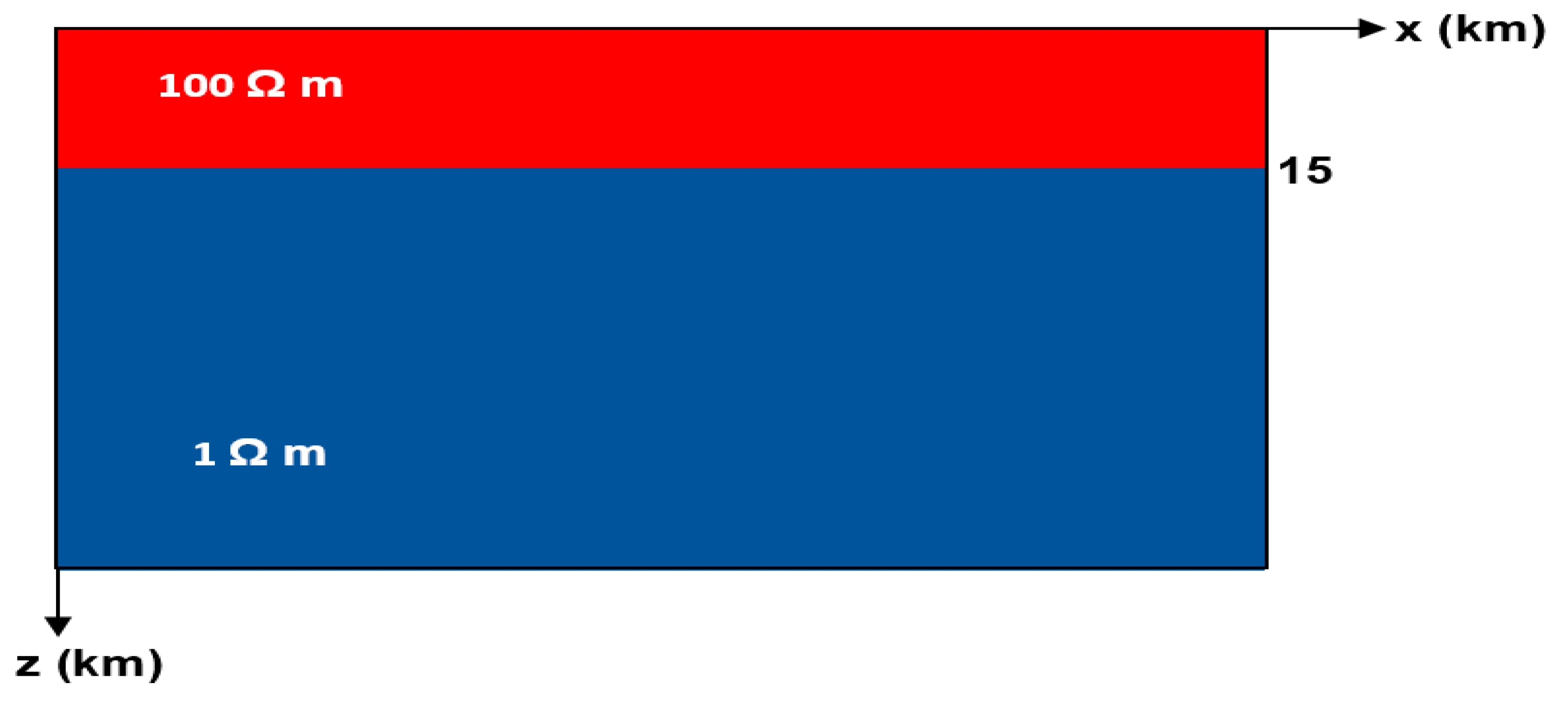
In verifying the accuracy of our finite volume algorithm, we synthesize an electromagnetic (EM) investigation for a homogeneous 1-D model. The background domain has a resistivity value of 1 Ω m, and a 15 km-thick layer of resistivity 100 Ω m is embedded in the background half-space (as indicated in Figure 2). A period range of 1–1000 s and E x polarization are considered for the EM modelling. The extent of the mesh is 40 km in both horizontal axes while 60 km in the vertical direction. Their number of cells used is 15, 15 and 84 in the x, y, z direction, respectively. The solid dash green lines indicate the analytical (A) solution while the red circle denotes the finite volume (FV) approach.
For this model, we compared our finite volume algorithm with the analytical solution [39]. From the plot in Figure 3a,b, it shows that the apparent resistivity and phase from our finite volume scheme are in good agreement with the analytic solution. It is also observed from Figure 3c,d that the relative error trend from the numerical solution rises at the transition zone between 2 to 200 s as a result of penetrating the conductive basement region.

3.2. Model 2

We consider a model consisting of two anomalies embedded in the two-layer background earth in a marine environment as indicated in Figure 4. The resistivity of the reservoir (hydrocarbon) is 100 Ω m with a size of 5000 × 5000 × 100 m3 while the resistivity of the salt dome is 33 Ω m and its volume 3000 × 3000 × 5000 m3. The incident electromagnetic wave is vertically propagated at frequency of 0.3 Hz.
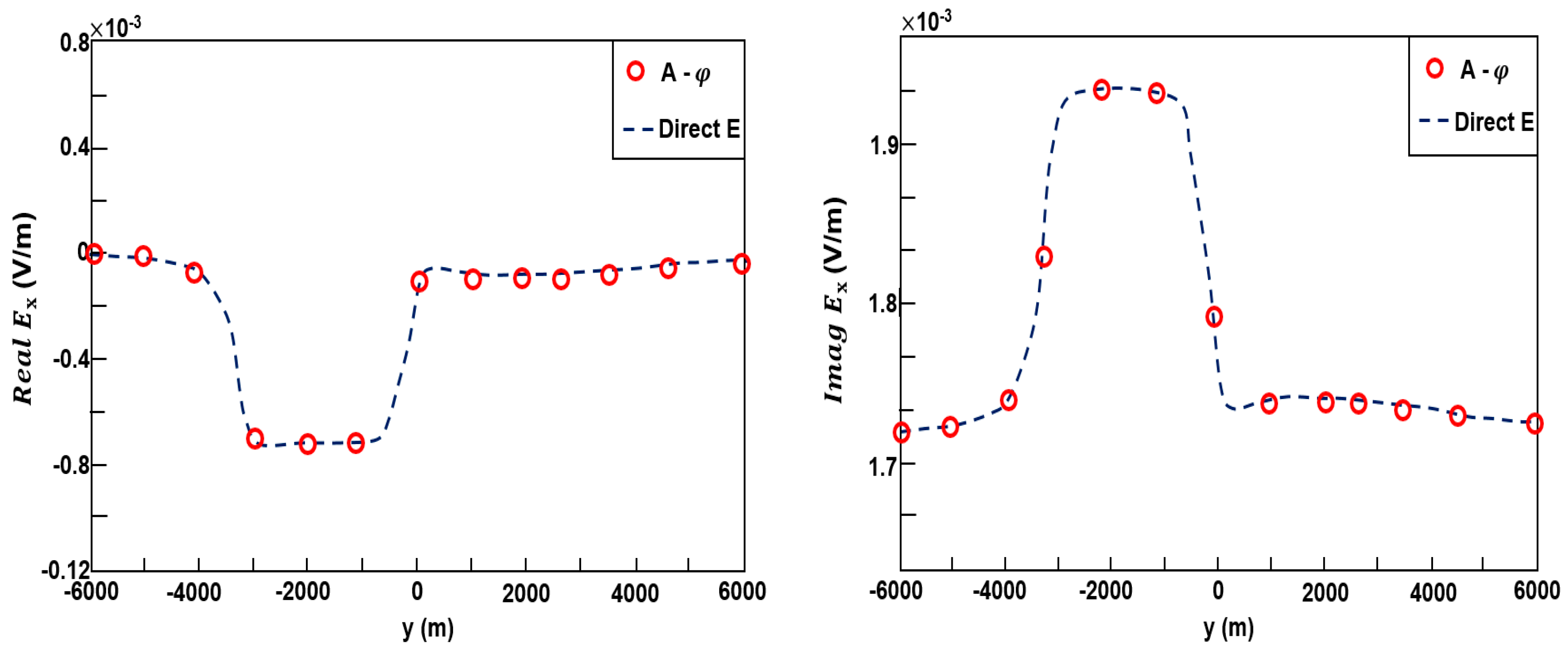
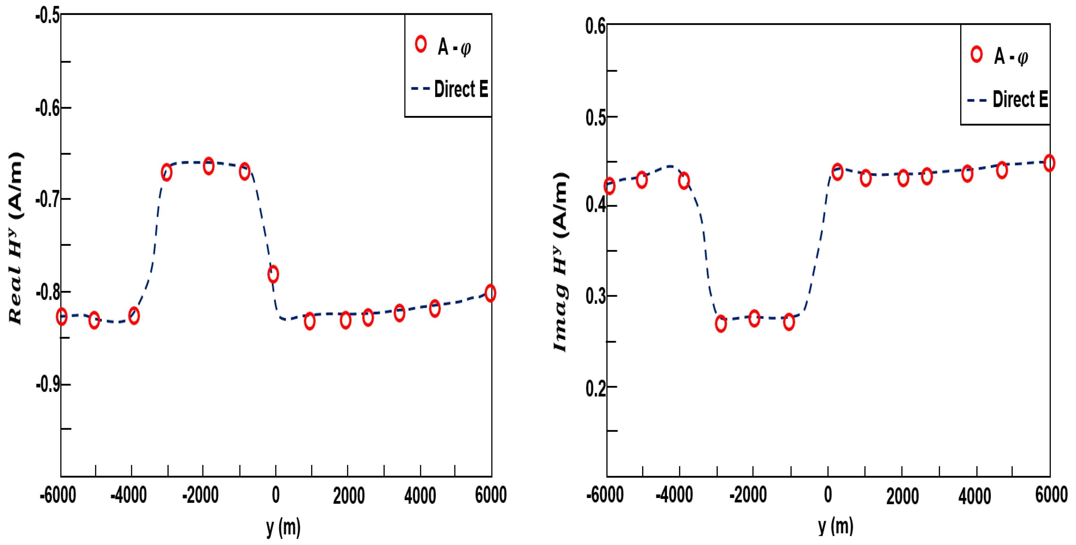
A comparison of our finite volume techniques using potential formulation was carried out with the finite volume method (Direct E) from [40]. For this investigation, the number of cells for the computational domain implemented are 45 × 45 × 35 while the dimension of the grid is 15, 15, 35 km in the x, y, z direction. The plots of the real and imaginary components for the electric and magnetic field of the E x polarization are shown in Figure 5 and Figure 6. The comparison indicates that both numerical schemes show an excellent agreement.
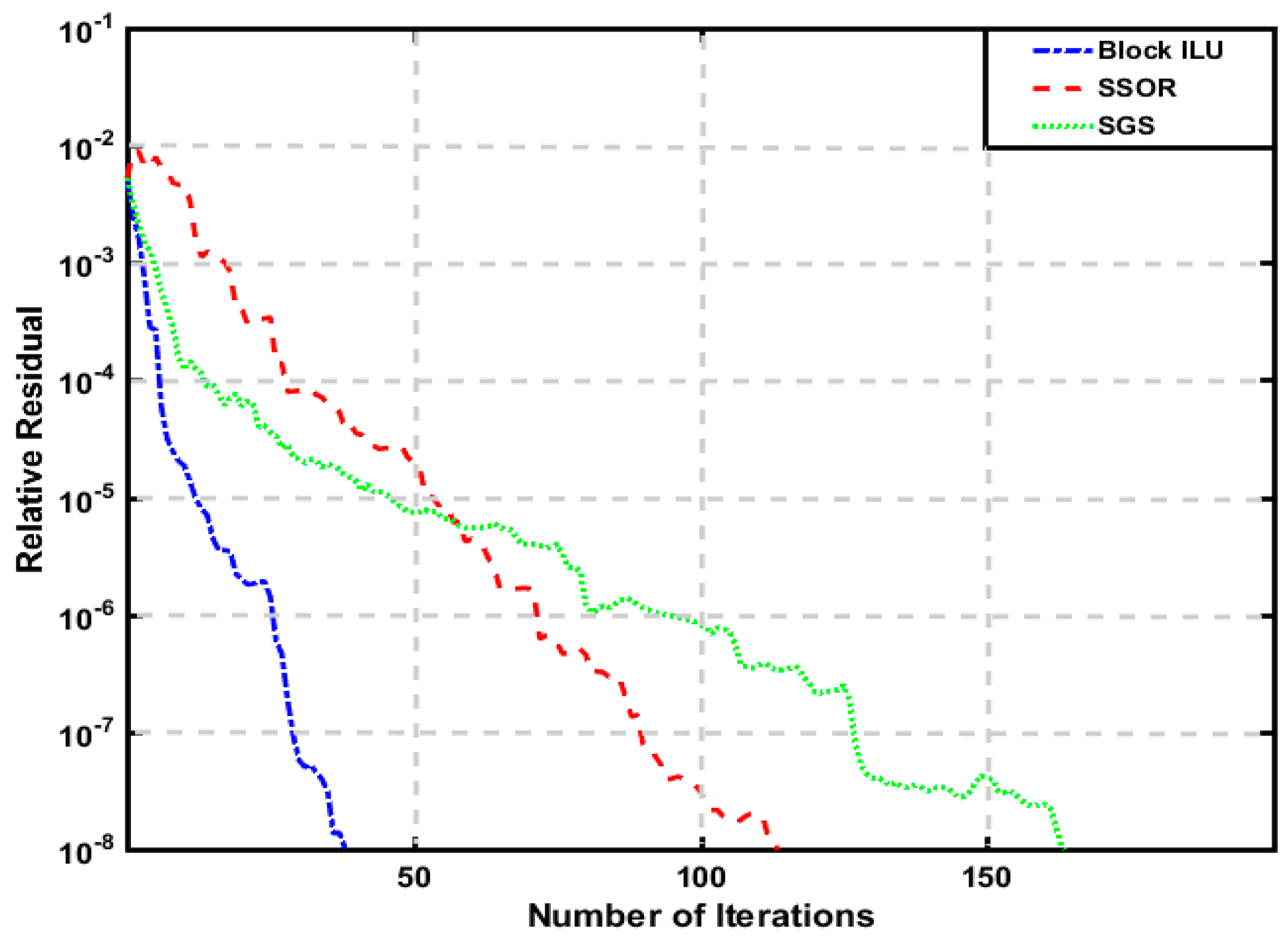
Furthermore, BiCGStab and QMR with block ILU and other preconditioners are examined to explore the best solver for this example. Figure 7 and Figure 8 signify the respective comparison of the convergence for BiCGStab and QMR with different preconditioners such as block ILU, SSOR, and SGS for the marine model. As revealed in the Figure 7 and Figure 8, the block ILU preconditioner shows the best convergence rate for both solvers among the tested preconditioners. With the same preconditioner, the BiCGStab solver outperforms the QMR, e.g., the block ILU for the BiCGStab converges at 45 iterations with computing time of 6 s while 140 iterations with a run time of 18 s for the corresponding QMR. Thus, the utilization of the block ILU preconditioner with BiCGStab iterative solver is favorable to simulate the EM responses for the marine model.

3.3. Model 3

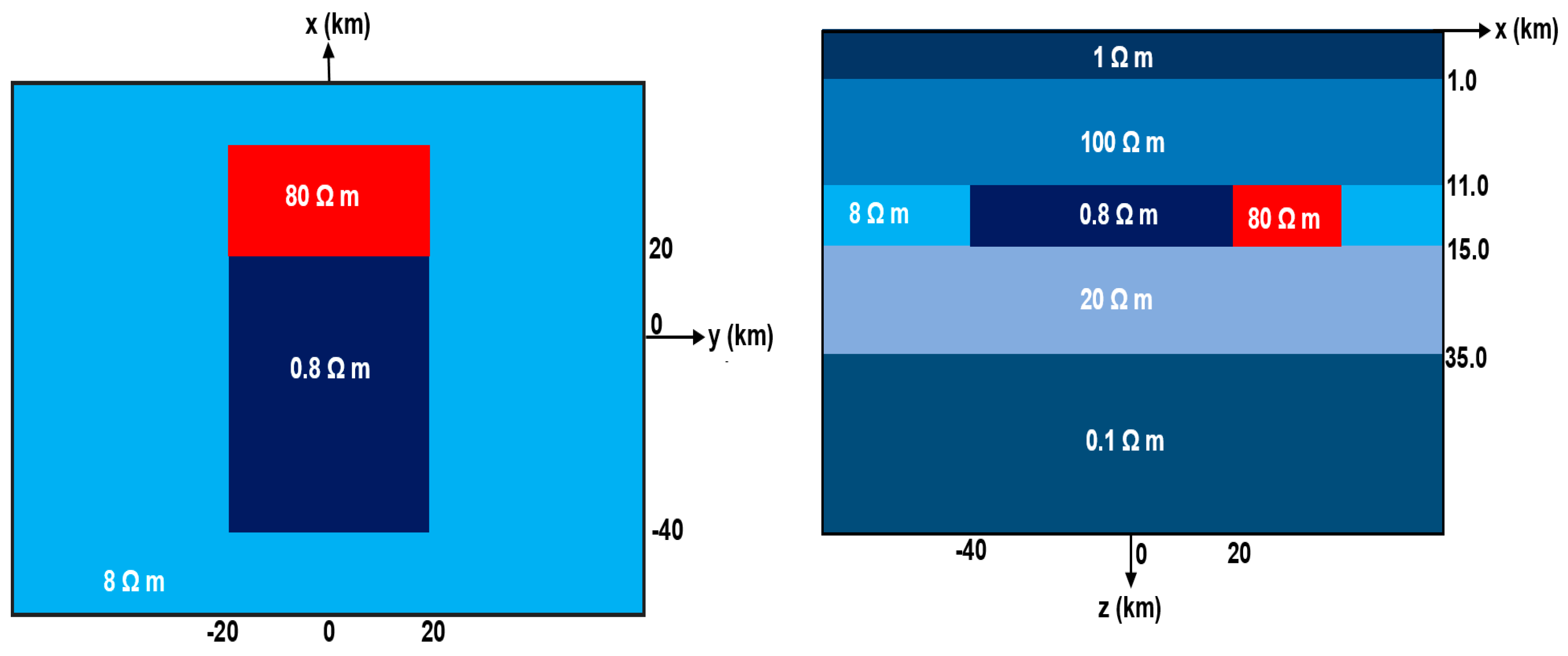
In this section, we compute the EM response for a three-dimensional (3-D) crustal model. For this model, the (two) anomalous rectangular bodies are situated at the third-layer of the (five) background horizons with resistivity values of 0.8 and 80 Ω m. The size of both anomalies are 60 × 40 × 4 km3 and 20 × 40 × 4 km3 respectively (Figure 9).
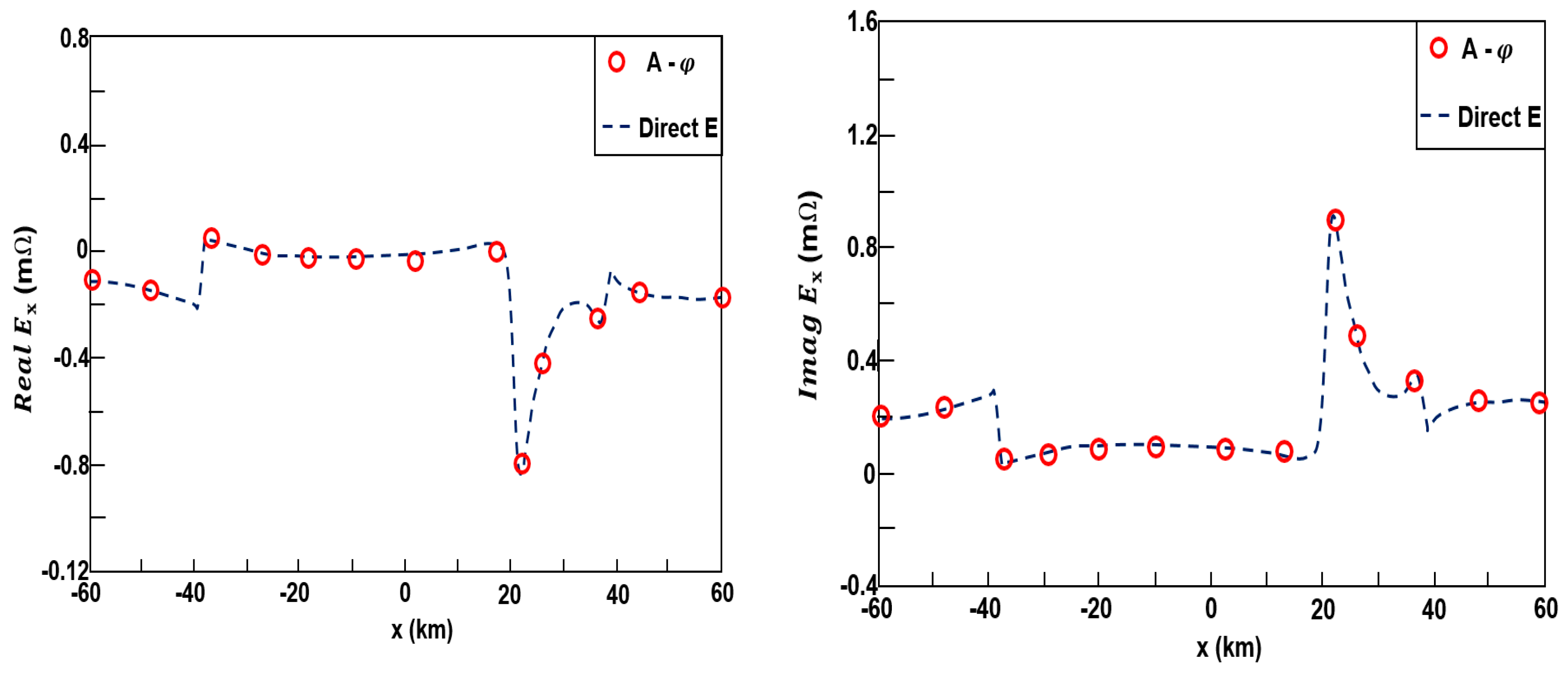
The computed grid domain is discretized into 60 × 53 × 28 cells in the x, y, and z-directions. Both horizontal direction is 115 km while the vertical extent is 185 km. A plane wave source at frequency of 0.001 Hz was used for the model. Figure 10 indicate the plot of the real and imaginary part of the normalized electric field for the E x polarization from our potential algorithm and direct E approach. The results are in good agreement with each other. Both imaginary and real parts of the E x reflect the horizontal changes in the model structure with sharp changes at the resistivity discontinuities. The real and imaginary part of the magnetic field for the E y polarization from our potential algorithm and direct E formulation are shown in Figure 11, again indicating that their results are consistent.
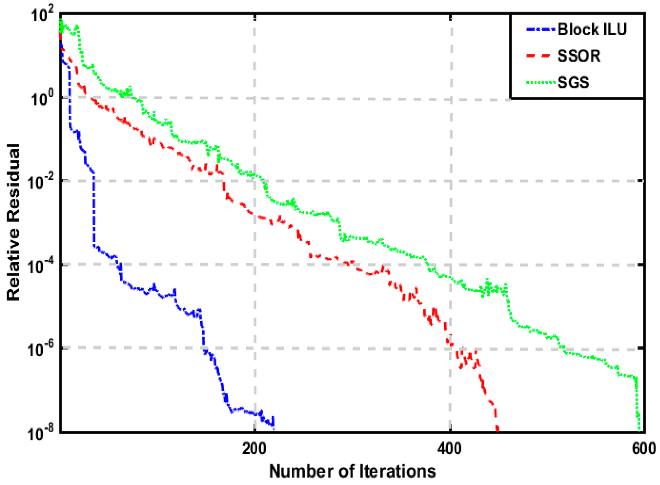
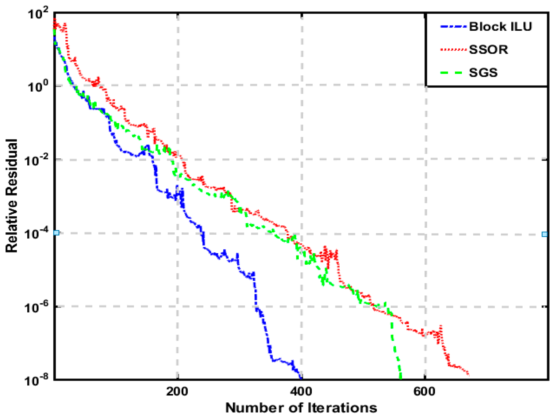
Additionally, we also examined the BiCGStab, and QMR solvers with various preconditioners (Block ILU, SSOR, and SGS) on this model. Moreover, as displayed in Figure 12 and Figure 13, the Block ILU pre-conditioner works exclusively better than the other preconditioner in this example. For this model, BiCGStab with the Block ILU preconditioner outperforms the corresponding QMR, e.g., the former one converges after 220 iterations while 395 iterations for QMR. Thus, the BiCGStab iterative solver preconditioned with the Block ILU shows a better preference for this test model.

4. Conclusions

We have developed a finite volume algorithm that solves the wide-band electromagnetic (EM) problem in the 3-D isotropic media. The concept is based on formulating the Maxwell’s equation into the magnetic vector ( A ) and electric scalar ( φ ) potential secondary formulation using the Lorentz gauge correction. We implement a block ILU preconditioner (and compared with other preconditioner) which helps to improve the convergence and rapidly solved the system matrix with iterative solvers such as the quasi-minimum residual (QMR), and bi-conjugate gradient stabilizer (BiCGStab).
For the model tested, the BiCGStab technique with block ILU preconditioner signifies better performance in terms of convergence rate than the other iterative scheme. The obtained results also revealed its efficacy and accuracy in comparison with other numerical methods. Future investigation will be conducted by applying the approach into the inversion routine.

Author Contributions

Conceptualization, M.B., J.L. and R.G.; methodology, M.B., J.L. and R.G.; software, M.B., J.L. and R.G.; validation, M.B., J.L. and R.G.; formal analysis, M.B., J.L. and R.G.; investigation, M.B., J.L. and R.G.; resources, J.L. and R.G.; writing—original draft preparation M.B.; writing—review and editing, M.B., J.L. and R.G.; visualization, M.B., J.L. and R.G.; supervision, J.L. and R.G.; project administration, J.L. and R.G.; funding acquisition, J.L.

Funding

This work is supported by National Natural Science Foundation of China (41674080).

Conflicts of Interest

The authors declare no conflict of interest.

References

  1. Zhdanov, M.S. Electromagnetic geophysics Notes from the past and the road ahead. Geophysics 2010, 75, 75A49–75A66. [Google Scholar] [CrossRef]
  2. Weiss, C. Project APhiD A Lorenz-gauged A-ϕ decomposition for parallelized computation of ultra-broadband electromagnetic induction in a fully heterogeneous earth. Comp. Geosci. 2013, 58, 40–52. [Google Scholar] [CrossRef]
  3. Avdeev, D.B. Three-dimensional electromagnetic modeling and inversion from theory to application. Surv. Geophys. 2005, 26, 767–799. [Google Scholar] [CrossRef]
  4. Wannamaker, P.E. Advances in three-dimensional magnetotelluric modeling using integral equations. Geophysics 1991, 56, 1716–1728. [Google Scholar] [CrossRef]
  5. Zhdanov, M.S. Geophysical Electromagnetic Theory and Methods; Elsevier: Oxford, UK, 2009. [Google Scholar]
  6. Liu, R.; Guo, R.W.; Liu, J.X.; Ma, C.Y.; Guo, Z.W. A hybrid solver based on the integral equation method and vector finite-element method for 3D controlled-source electromagnetic method modeling. Geophysics 2018, 83, E319–E333. [Google Scholar] [CrossRef]
  7. Avdeev, D.B.; Kushinov, A.V.; Pankratov, O.V.; Newman, G.A. High-Performance three-dimensional electromagnetic modelling using modified Neumann Series Wide-band numerical solution and examples. J. Geomag. Geoelectr. 1997, 49, 1519–1539. [Google Scholar] [CrossRef]
  8. Hursán, G.; Zhdanov, M.S. Contraction integral equation method in three-dimensional electromagnetic modelling. Radio Sci. 2002, 37, 1–13. [Google Scholar] [CrossRef]
  9. Singer, B. Electromagnetic integral equation approach based on contraction operator and solution optimization in Krylov subspace. Geophys. J. Int. 2008, 175, 857–884. [Google Scholar] [CrossRef]
  10. Kruglyakov, M.; Kuvshinov, A. Using high-order polynomial basis in 3-D EM forward modelling based on volume integral equation method. Geophys. J. Int. 2018, 213, 1387–1401. [Google Scholar] [CrossRef]
  11. Mackie, R.L.; Smith, J.T.; Madden, T.R. Three-dimensional electromagnetic modelling using finite difference equations. The magnetotelluric example. Radio Sci. 1994, 29, 923–993. [Google Scholar] [CrossRef]
  12. Streich, C. 3D finite-difference frequency-domain modeling of controlled source electromagnetic data: Direct solution and optimization for high accuracy. Geophysics 2009, 74, F95–F105. [Google Scholar] [CrossRef]
  13. Weiss, C.J. Triangulated finite difference methods for global-scale electromagnetic induction simulations of whole mantle electrical heterogeneity. Geochem. Geophys. Geosys. 2010, 11. [Google Scholar] [CrossRef]
  14. Egbert, G.D.; Kelbert, A. Computational recipes for electromagnetic inverse problems. Geophys. J. Int. 2012, 189, 251–267. [Google Scholar] [CrossRef]
  15. Simpson, F.; Bahr, K. Practical Magnetotellurics; Cambridge University Press: Cambridge, UK, 2005. [Google Scholar]
  16. Monk, P. Finite Element Methods for Maxwell’s Equations; Oxford University Press: Oxford, UK, 2003. [Google Scholar]
  17. Ren, Z.; Kalscheuer, T.; Greenhalgh, S.; Maurer, H. A goal-oriented adaptive finite-element approach for plane wave 3-D electromagnetic modelling. Geophys. J. Int. 2013, 194, 700–718. [Google Scholar] [CrossRef]
  18. Sugeng, F. Modeling the 3D TDEM response using the 3D full-domain finite element method based on the hexahedral edge-element technique. Explor. Geophys. 1998, 29, 615–619. [Google Scholar] [CrossRef]
  19. Mitsuhata, Y.; Uchida, T. 3D magnetotelluric modeling using the T-Omega finite-element method. Geophysics 2004, 1, 108–119. [Google Scholar] [CrossRef]
  20. Nam, M.; Kim, H.; Song, Y.; Lee, T.; Son, J.; Suh, J. 3D magnetotelluric modelling including surface topography. Geophys. Prosp. 2007, 55, 277–287. [Google Scholar] [CrossRef]
  21. Ansari, S.M.; Farquharson, C.G. 3D finite-element forward modeling of electromagnetic data using vector and scalar potentials and unstructured grids. Geophysics 2014, 79, 1–17. [Google Scholar] [CrossRef]
  22. Puzyrev, V.; Koldan, J.; de la Puente, J.; Houzeaux, G.; Vázquez, M.; Cela, J.M. A parallel finite-element method for three-dimensional controlled-source electromagnetic forward modelling. Geophys. J. Int. 2013, 193, 678–693. [Google Scholar] [CrossRef]
  23. Börner, R.U.; Ernst, G.O.; Spitzer, K. Fast 3-D simulation of transient electromagnetic fields by model reduction in the frequency domain using Krylov subspace projection. Geophys. J. Int. 2008, 173, 766–780. [Google Scholar] [CrossRef]
  24. Haber, E.; Ascher, U.M. Fast finite volume simulation of 3D electromagnetic problems with highly discontinuous coefficients. SIAM J. Sci. Comput. 2001, 22, 1943–1961. [Google Scholar] [CrossRef]
  25. Jahandari, H.; Farquharson, C.G. Finite-volume modelling of geophysical electromagnetic data on unstructured grids using potentials. Geophys. J. Int. 2015, 202, 1859–1876. [Google Scholar] [CrossRef]
  26. Um, E.S.; Harris, J.M.; Alumbaugh, D.L. 3D time-domain simulation of electromagnetic diffusion phenomena: A finite-element electric-field approach. Geophysics 2010, 4, F115–F126. [Google Scholar] [CrossRef]
  27. Smith, J.T. Conservative modeling of 3-D electromagnetic fields Part II biconjugate gradient solution and an accelerator. Geophysics 1996, 61, 1319–1324. [Google Scholar] [CrossRef]
  28. Farquharson, C.G.; Miensopust, M.P. Three-dimensional finite element modelling of magnetotelluric data with a divergence correction. J. Appl. Geophys. 2011, 75, 699–710. [Google Scholar] [CrossRef]
  29. Morisue, T. A comparison of the Coulomb gauge and Lorentz gauge magnetic vector potential formulations for 3D eddy current calculations. IEEE Trans. Mag. 1993, 29, 1372–1375. [Google Scholar] [CrossRef]
  30. Aruliah, D.A.; Ascher, U.M.; Haber, E.; Oldenburg, D.W. A method for the forward modelling of 3D electromagnetic quasi-static problems. Math. Models Meth. Appl. Sci. 2001, 11, 1–21. [Google Scholar] [CrossRef]
  31. Badea, E.A.; Everett, M.E.; Shen, L.C.; Weiss, C.J. Effect of background fields on three-dimensional finite element analysis of induction logging. Radio Sci. 2001, 36, 721–729. [Google Scholar] [CrossRef]
  32. Schwarzbach, C.; Boerner, R.U.; Spitzer, K. Three-dimensional adaptive higher-order finite element simulation for geo-electromagnetics—A marine CSEM example. Geophys. J. Int. 2011, 187, 63–74. [Google Scholar] [CrossRef]
  33. Haber, E.; Ascher, U.M.; Aruliah, D.A.; Oldenburg, D.W. Fast simulation of 3D electromagnetic problems using potentials. J. Comp. Phys. 2000, 163, 150–171. [Google Scholar] [CrossRef]
  34. Saad, Y. Iterative Methods for Sparse Linear Systems; Society for Industrial and Applied Mathematics: Philadelphia, PA, USA, 2003. [Google Scholar]
  35. Chave, A.; Jones, A. The Magnetotelluric Method—Theory and Practice; Cambridge University Press: Cambridge, UK, 2012. [Google Scholar]
  36. Newman, G.A.; Alumbaugh, D.L. Frequency-domain modelling of airborne electromagnetic responses using staggered finite differences. Geophys. Prospect. 1995, 43, 1021–1042. [Google Scholar] [CrossRef]
  37. Freund, R.W.; Nachtigal, N.M. QMR: A quasi-minimal residual method for non-Hermitian linear systems. Numer. Math. 1991, 60, 315–339. [Google Scholar] [CrossRef]
  38. Van der Vorst, H.A. BI-CGSTAB A fast and smoothly convergent variant of BiCG for the solution of nonsymmetric linear systems. SIAM J. Sci. Stat. Comp. 1992, 13, 631–644. [Google Scholar] [CrossRef]
  39. Wait, J.R. Propagation of radio waves over a stratified ground. Geophysics 1953, 20, 416–422. [Google Scholar] [CrossRef]
  40. Weiss, C.J.; Constable, S. Mapping thin resistor and hydrocarbons with marine EM methods part II—Modeling and analysis in 3D. Geophysics 2006, 71, G321–G332. [Google Scholar] [CrossRef]
Figure 1. The finite volume grid discretization for the system of equation.
Applsci 09 01328 g001
Figure 2. Vertical cross-section view of the model 1 with the anomaly in a homogeneous half-space.
Applsci 09 01328 g002
Figure 3. The plot of the (a) apparent resistivity (b) phase for the E x polarization using the finite volume (FV) approach and the analytical (A) method. And the (c) apparent resistivity relative error (d) phase relative error of the finite volume method. The solid dash green lines indicate the analytical (A) solution while the red circle denotes the finite volume (FV) approach. And the solid dash red lines indicate the relative error for the FV method.
Applsci 09 01328 g003
Figure 4. The planar and vertical cross-section view of the marine model 2. The anomalous bodies are embedded in a homogenous layer below the sea water.
Applsci 09 01328 g004
Figure 5. The plot of the E x polarization (real and imaginary) calculated using the Potential and Direct E formulation.
Applsci 09 01328 g005
Figure 6. The plot of the H y for the E x polarization (real and imaginary) calculated using the Potential and Direct E formulation.
Applsci 09 01328 g006
Figure 7. The convergence plot of various preconditioners with BiCGStab for marine model 2.
Applsci 09 01328 g007
Figure 8. The convergence plot of various preconditioners with QMR for marine model 2.
Applsci 09 01328 g008
Figure 9. The planar and vertical cross-section view of the model 3. The anomalous bodies are embedded in the middle homogenous layer.
Applsci 09 01328 g009
Figure 10. The plot of the real and imaginary component for the normalized electric field of the E x polarization calculated using the Potentials and Direct E formulation.
Applsci 09 01328 g010
Figure 11. The plot of the real and imaginary component for the magnetic field of the E y polarization calculated using the Potential and Direct E formulation.
Applsci 09 01328 g011
Figure 12. The convergence plot of different preconditioners with BiCGStab for the model 3.
Applsci 09 01328 g012
Figure 13. The convergence plot of different preconditioners with QMR for the model 3.
Applsci 09 01328 g013