Abstract
The increasing share of renewable energies requires the installation of large-scale electricity storage capacities in addition to grid expansion. Significant contribution to reach this goal is provided by adiabatic compressed air energy storage power plants (A-CAES), key elements in future electricity transmission systems. This technology allows efficient, local zero-emission electricity storage on the basis of compressed air in underground caverns in combination with thermal energy storage systems and, in contrast to pumped storage power plants (PSPP), it demands no overground geological requirements. Despite the achieved success of A-CAES systems in terms of efficiency and cost, further improvements in dynamics and flexibility are needed. One promising solution to fulfil these dynamic requirements is based on the integration of an additional power-to-heat element (P2H) operating during the charging periods. This modification allows increased power plant flexibility and further cost reductions due to increased thermal storage densities but is simultaneously associated with concept-dependent decreasing total round trip efficiencies. For the identification of suitable configurations, adequate concepts must be elaborated, and the influence on round trip efficiency as well as on cost reduction potential must be investigated. For this purpose, a system model for a two-stage A-CAES configuration is established and used for large simulation studies related to P2H locations and power, thermal energy storage systems, and central process variables. Therefore, time-efficient model reductions with well-justified assumptions are conducted, offering a simplified transient implementation of thermal energy options in the system simulation. On the basis of a promising P2H configuration including high potentials for cost reduction and moderate losses in round trip efficiency, an alternative concept is presented offering high exergetic utilization and additional cost reductions, which can be treated as a base for upgrading the existing CAES power plants and for modifying operational concepts.
1. Introduction
The transformation of the electrical energy system from conventional to renewable energy sources enforces significant extensions of grid and storage capacities due to the fluctuating nature of wind and solar power. Relevant contributions for reaching this goal and for securing of energy supply are offered by large-scale storages that allow grid-compatible extraction and supply of electrical energy []. Today, the electrical energy storage systems (EES) used, with high powers of up to 1.5 GW, several hours of storage capacity, and high round trip efficiencies, are pumped storage power plants (PSPP). However, further extensions of this technology are limited because of geological restrictions and high capital costs of up 600–2000 $/kW [,]. As an alternative commercial technology, compressed air energy storage systems (CAES) offer the potential for high storage capacities and powers with lower overground geological impacts [,,,]. The first power plant was built at Huntorf in Germany in 1978 [], followed, in 1991, by a power plant in McIntosh, USA []. Here, in times of low grid load, electrical energy is used to compress and store air in underground caverns. During times of required peak loads, the cold pressurized air is expanded in a modified gas turbine and heated via natural gas combustion. Due to the gas firing, lower round trip efficiencies are achieved with CAES systems compared with PSPP.
Aside from these concepts, alternative large-scale technologies with high storage capacities have been investigated in several research and development activities [,]. Promising configurations are based on flow batteries [,], hydrogen [], pumped heat energy storage (PHES) [], and modifications of the CAES system towards an adiabatic operation (A-CAES) offering increased round trip efficiencies [,,]. Considering the technology-dependent scientific and economic challenges of these mentioned concepts, relating to lifetime, efficiency, electrical power, and investment costs, only two EES technologies show marketability and potential in short-term realization: the A-CAES and PHES systems. Both require thermal energy storage systems (TES) as central elements to increase total round trip efficiency and to allow a local zero-emission operation. Heat - while compression - is transferred to the storage medium and reintegrated into the gaseous working fluid during the discharging period to supply the gas turbine with the required thermal energy and to avoid natural gas combustion. With the integration of TES systems into the cyclic operation procedure, additional parasitics, in terms of pressure losses, are involved. In particular, PHES systems are highly affected by pressure losses leading to significant decreasing total round trip efficiencies [,,,,,,]. Therefore, extensive design calculations embedded in overall thermodynamic system simulations are needed in order to identify efficient configurations with low parasitics. In contrast, A-CAES systems allow robust configurations due to their lower sensitivity to pressure losses, allowing increased design freedoms in TES arrangements. In principle, all heat storage technologies offering minimal exergy losses during heat transfer have been considered []. However, because of the gaseous heat transfer medium and the elevated temperatures inside the cyclic operation, storage media based on solid and liquid inventory materials meet the requirements of thermal efficiency and costs particularly well. Alternative TES concepts based on phase change materials (PCM) were investigated in a study [] to reduce the amount of entropy generated from the heat exchange process, leading to an improved overall efficiency of the system.
In order to increase the performance of CAES configurations, different system extensions have been investigated to utilize the waste heat carried in turbine exhaust during discharge [] or to allow cooling, heating, and electrical generation []. Alternative ideas are based on an isothermal CAES configuration to eliminate the need for fuel and high-temperature thermal energy storages []. Additional improvements to such a concept have been investigated through the integration of PCM in order to control the isothermal operation during compression and expansion [].
In spite of the achievements reached for various A-CAES design configurations [,,,] accompanied by significant cost reductions [], further improvements in flexibility and economic efficiency are needed. For this purpose, the integration of P2H elements operating during charging periods inside the power plant configuration is investigated, allowing increased operating times as well as participation in the secondary control market and thus improved competitiveness. This modification allows increased power plant flexibility and further cost reductions due to increasing thermal storage densities but is simultaneously associated with concept-dependent decreasing total round trip efficiencies.
The first results of such a modified A-CAES configuration were published in reference []. Here, for a constant set of boundary conditions and an exemplary integration location inside an A-CAES configuration, the potentials for increased storage densities associated with decreasing component sizes are outlined. For holistic considerations of such concepts, an overall system analysis is needed to identify operational conditions, P2H locations, and system configurations offering high efficiencies and cost reductions potentials. For that purpose, investigations for different P2H integration locations accompanied by adaptations in pressure ratios and component efficiencies are conducted. Additionally, an alternative based on fundamental results regarding operational concepts and P2H locations configuration is presented, which offers high exergetic utilization and additional cost reduction potentials and can be treated as a base for upgrading the existing CAES power plants.
2. Methodology
For increased flexibility and cost efficiency of A-CAES systems, modifications are investigated through the integration of the P2H element. For this purpose, a promising configuration is based on an original two-stage compression and expansion process, in which sensible thermal energy storage systems are integrated in each pressure stage to conserve the heat during compression (Figure 1a). Therefore, a regenerator-based solid-media heat storage is used in the first stage in the presence of low to moderate pressure levels, and a two-tank heat storage system based on a liquid medium integrated via a heat exchanger is used in the second high-pressure stage. Additionally, two safety coolers are required to ensure the specified temperature inlet conditions of the high-pressure compressor and the cavern.
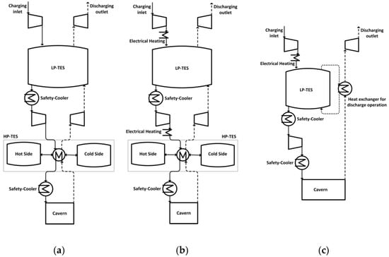
Figure 1.
Reference concept (a); extended concept (b) with power-to-heat element (P2H) elements in the low- and/or in the high-pressure stage; alternative concept (c) with P2H element in the low-pressure (LP) stage and without high-pressure thermal energy storage systems (HP-TES).
On the basis of this original A-CAES configuration (reference concept), system extensions consisting in the integration of P2H elements (extended concept) and system modifications (alternative concept) are investigated. Figure 1 schematically illustrates the investigated concepts.
The modified system (Figure 1b) is based on the original A-CAES system with P2H elements in the low- and high-pressure range before the thermal energy storage systems. This concept allows the investigation of electrical heating in the low- or in the high-pressure ranges individually, as well as in both pressure ranges. The basic idea behind these modifications includes an additional electrical heating stage during charging to elevate the temperature after compression, thus allowing increased thermal storage densities during thermal cyclic operation.
In contrast, the alternative concept is based on only one thermal energy storage system (Figure 1c). Here, heat during compression in the low-pressure stage—additionally elevated by the P2H element—is stored in the regenerator-based heat storage and cooled down during compression in the second stage. Differing from the previous concepts, the temperature of the pressurized air leaving the cavern during discharging is elevated by the stored heat via a heat exchanger and expanded over the whole pressure range to ambient conditions.
Additional potentials are offered by the P2H elements to both concepts by simultaneous adaptations of the pressure ratios to utilize the exergetic effects due to the elevated temperatures. In order to identify efficient configurations on the base of central specifications with increased storage densities compared to the reference concept, variation studies are conducted considering TES efficiencies (ηTES), electrical heating power (PP2H), and pressure in the first stage (pLP). For clarification, this simulation methodology is illustrated in Figure 2.
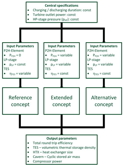
Figure 2.
Simulation methodology for the reference, the extended, and the alternative concepts, with central specifications, input, and output parameters.
In the variation study of the reference concept without additional electric heating, a constant pressure in the first stage is set to achieve equal pressure ratios in all stages. With respect to TES efficiency, simulation runs are conducted to identify suitable solutions with high round trip efficiencies and moderate dimension sizes of the TES components. On the basis of appropriate TES efficiencies, variations studies of the extended and alternative concepts are performed in order to investigate the effects of the first-stage pressure level and of the additional electric heating on total round trip efficiency and component-specific results.
Because of the same set of specifications for all concepts under investigation, the output parameters allow comparative statements regarding system efficiencies and component sizes. These component sizes and the associated operational boundary conditions will enable economic evaluations of the systems via adequate cost models in future works. In this contribution, the component output parameters substantially include the data for dimensioning the central components inside the systems as well as their P2H specific changes and thus an economic evaluation:
- TES—volumetric thermal storage density: Q/V [kWh/m3]
- HTX—heat exchanger size: kO [kW/K]
- Cavern—cyclic stored air mass: mF [t]
- Compressor power: ΣPCompressor [MW]
With the purpose to identify cost reduction potentials through P2H elements inside a two-stage A-CAES configuration and losses in round trip efficiencies, simulation studies are performed for the concepts mentioned in Figure 1. For modelling such systems, a detailed formulation of the central components—the thermal energy storage systems—is necessary, including the transient behavior of regenerator-based storage options.
3. Modelling
For simulation studies of the concepts to be investigated, a modelling of each central component is required. In order to allow time-efficient calculations, different modelling depths are used depending on the component’s characteristics. From this point of view, the components can be divided in stationary and transient ones. A component with pure transient behavior requiring higher modelling demand is given by the regenerator-based thermal energy storage. In contrast, the two-tank thermal energy storage as well as the heat exchanger can be treated as stationary components, allowing a compact formulation.
For modelling of turbomachines and cavern without losing relevant systemic effects, simplified formulations are suitable. For this purpose, isentropic changes in state are used to determine the outlet temperatures of the turbomachines, and isothermal changes to calculate the required cavern volume defined by the specified outlet temperature after cooling. Analogically, the P2H element is modelled in a simple way by assuming an ideal isobaric transformation of electrical power to thermal power. Promising technologies for a large-scale P2H element are available by inductive and conductive procedures [,]. Detailed information regarding inductive techniques for the system under investigation can be found in reference [].
Because of the significant modelling effort, the regenerator-based and two-tank thermal energy storage option including the heat exchanger are described in a compact way in the following section.
3.1. Low-Pressure (LP)-TES: Regenerator
The time-varying temperature field during thermal cyclic operation is calculated with a thermal model considering the storage media as a heterogeneous porous medium []. Based on this formulation, a simplified thermal model can be derived with well-justified negligence of the storage capacity term of the gaseous medium and of the axial conduction terms due to low heat conductivities of both media and to thermal losses for large-scale dimensions. Assuming a one-dimensional axial model and normalization in time t* and space z*, the heterogeneous model can be expressed as:
This formulation describes the thermal behavior of the regenerator-based thermal energy storage with only two dimensionless parameters, the reduced period duration Π and the reduced regenerator length Λ.
Here, TS and TF represent the solid medium and the heat-transfer fluid temperature, O the heat-transfer surface, τ the charge/discharge duration, mS the total storage mass, the mass flow rate, and cS and cP the specific heat capacities of the solid and fluid, respectively. The total heat transfer coefficient k regarding the thermal resistance of the inventory option is defined as in references [,]. Inside the simulation studies, a packed bed is assumed as an inventory option with a heat-transfer coefficient as defined by reference [].
The expression in Equations (1) and (2) are solved numerically by using a backward finite-difference method in space for the fluid phase. Subsequently, the resulting set of differential-algebraic equations is solved in time with a commercial simulation tool (Matlab) to obtain the required temporal fluid outlet temperatures during the cyclic operation.
For a simplified implementation of the resulting time-varying regenerator fluid outlet temperatures in the A-CAES system simulations, a temporal averaged fluid outlet temperature () and a regenerator efficiency ηLP-TES are used, expressed by the cyclic inlet fluid temperatures (, ):
Assuming equal charging–discharging duration, only one regenerator efficiency is required. Because of the dependency of the regenerator efficiency on the dimensionless parameters Π and Λ given in Equations (1) and (2) and on systemic factors (mass flow rate and inlet temperatures), the LP-TES storage mass/volume is calculated. For that, additional specifications regarding the inventory option and the bed diameter are need (see Section 4).
3.2. Hihg-Pressure (HP)-TES: Two-Tank Thermal Energy Storage
The thermal cyclic behavior of the two-tank storage system is mainly determined by the efficiency of the heat exchanger transferring heat from the air towards the liquid storage medium during charging and back during discharging. Assuming constant material properties and negligence of thermal losses and thermal inertia effects, analytical NTU-models can be used [,] to describe the thermal behavior of the heat exchanger (see Equation (7)).
In consideration of the heat and mass balances, as well as of equal charging–discharging duration, the hot (TF,hot) and cold temperatures (TF,cold) of the liquid storage medium inside the two-tank system can be determined by:
Here, and represent the heat-exchanger air inlet temperatures of the investigated A-CAES systems, and ηHP-TES the heat-exchanger efficiency. On the basis of the defined assumption of equal charging–discharging duration, and thus equal mass flow rates, only one heat exchanger efficiency is required. Finally, the size of the heat exchanger (kOTES-HTX) in counter-flow is calculated through:
With this fundamental set of equations, the temperatures of the liquid storage medium and of the pressurized air leaving the heat exchanger are determined inside the cyclic operation. On the basis of the systemic results and a defined liquid storage medium (see Section 4), the HP-TES storage masses and the volumes are calculated, respectively.
4. Results
In order to identify suitable integration locations for the P2H element and to evaluate the potentials in cost reduction as well as the losses in round trip efficiency, simulation studies based on the concepts mentioned in Figure 1 are performed. For this purpose, the component models described in Section 3 are connected according to the conceptual schemes. Inside the calculation procedure, an iterative adaption of the mass flow rates is conducted to achieve constant turbine power and to fulfil the criterion of balanced air mass inside the cavern.
On the basis of a set of central specifications listed in Table 1, variation studies are conducted related to thermal storage energy efficiencies (ηLP-TES, ηHP-TES), electrical heating power (PP2H), and low-pressure stage (pLP). Here, pressure losses are neglected for TES and heat exchangers but regarded for the cavern because of the high underground piping length. Ambient conditions (10 °C, 1 bar) are set for the air entering the investigated systems.

Table 1.
Central specifications for system simulations.
The basic specification parameters inside the system simulations include the turbine power and the charging–discharging duration. In terms of operation durations, a nocturnal, low-price 6 h charging period is chosen, followed by a morning, high-price 6 h discharging period, with low share of renewable photovoltaic energies and high consumption needs. In order to investigate two-stage large-scale A-CAES configurations with underground caverns as mechanical energy storage systems, high turbine outlet powers of 65 MW and a maximum high pressure of 65 bar are selected. Comparable specifications, as summarized in Table 1, can be found in conventional CAES [,] as well as in A-CAES power plants [].
Additionally, further parameters are required regarding the thermal storage systems. Here, mineral oil (Therminol VP-1) is considered as liquid medium for the high-pressure thermal energy storage, limited by maximum operation temperature of 400 °C. For the low-pressure thermal energy storage system, a ceramic packed bed with a particle diameter of 0.05 m, a void fraction of 40%, and a bed diameter of 10 m is selected. With these sets of specifications and the thermal models described in Section 3, the storage masses and the volumes are calculated, as well as the HP-TES heat exchanger size.
In the following, simulation studies are conducted in order to identify cost reduction potentials and losses in round trip efficiency. Firstly, results are presented on the basis of the reference concept in order to evaluate the impact of thermal storage efficiencies on total round trip efficiency. Subsequently, the influence of the electrical heating power is investigated depending on its locations and the pressure level in the first stage, for the extended and alternative concepts. Finally, a comparison of the investigated concepts is presented.
4.1. Reference Concept
On the basis of the compact formulated thermal models in Section 3, variation studies regarding the thermal storage efficiencies (ηLP-TES, ηHP-TES) are conducted for the reference concept, allowing to determine the total round trip efficiency, volumetric thermal storage densities, HP-TES heat exchanger size, charging–discharging fluid masses, and compressor powers.
For this purpose, the pressure in the first stage (pLP) is set to 8.1 bar, leading to equal pressure ratios in all stages during compression. The resulting total round trip efficiencies as well as the thermal storage densities are illustrated in Figure 3 for variations simulations relating to the thermal storage efficiencies.
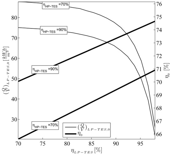
Figure 3.
Total round trip efficiency and thermal storage density in relation to thermal storage efficiencies.
The results show an increase in total round trip efficiency (η0) with increasing thermal storage efficiencies. Assuming a highly efficient HP-TES with ηHP-TES = 90%, up to 74.2% total round trip efficiency is achievable with LP-TES efficiencies of ηLP-TES = 95%. Simultaneously, a dramatic decrease in thermal storage density is visible for the regenerator-based LP-TES starting at ηLP-TES efficiencies of more than 90%. This characteristic is based on increasing requirements for high temporal averaged discharging fluid outlet temperatures, leading to a significant increased ratio of the iteratively calculated dimensionless parameters Π and Λ defined in Equations (1) and (2).
As illustrated in Figure 3, higher LP-TES thermal storage densities are reached with lower HP-TES efficiencies. This system-related effect results from decreasing LP-TES inlet temperatures during discharging—thus increasing the total temperature spread—caused by lower HP-TES and HP-turbine outlet temperatures, respectively. At the same time, lower HP-TES efficiencies lead to decreasing HP-TES heat exchanger sizes (kOTES-HTX,0) from 3100 kW/K at ηHP-TES = 90% to 860 kW/K at ηHP-TES = 70% and to decreasing HP-TES thermal storage densities from 63 kWh/m3 at ηHP-TES = 90% to 49 kWh/m3 at ηHP-TES = 70%, due to reduced temperature spread inside the liquid storage medium. Further effects are associated with TES efficiencies, for example, the resulting mass flow rates—and, thus, the compressor and cavern sizes—and need to be optimized in a techno-economic way.
In order to investigate the influence of the additionally implemented P2H option on total round trip efficiency and cost reduction potential, thermal storage efficiencies of 90% are chosen for the reference case. Central results regarding the round trip efficiency (η), volumetric thermal storage densities (Q/V), HP-TES heat exchanger size (kOTES-HTX), charging–discharging fluid masses (mF), and compressor powers (ΣPCompressor) are summarized in Table 2.
Table 2.
Central results for the reference concept based on thermal storage efficiencies of 90% with a pressure level in the first stage of pLP = 8.1 bar during compression.
4.2. Extended Concept
The extended concept pointed out in Figure 1 provides an additional electrical heating in the low- or in the high- pressure stages, as well as depending, proportionally, on both pressure stages. To identify suitable configurations with low losses in round trip efficiency and high potentials in component size reduction, simulation studies are performed related to the pressure in the first stage (pLP) and the heating power and its distribution (xLP,P2H) in the LP and HP ranges, respectively. Here, the LP pressure variations are limited by the maximum compressor outlet temperatures of 350 °C for both stages, leading to LP compression pressures between 5.3 bar and 12.4 bar and pressure ratios π between 0.7 and 1.5 bar compared to an equal pressure ratio in all stages of pLP = 8.1 bar. Additionally, inside the simulation studies with varying electric heating powers, the maximum operational temperature for the HP-TES liquid storage medium of 400 °C is considered.
Due to highly linear behaviors with increasing electrical heating power, P2H-specific results are illustrated. These results—representing the effect of decreasing total round trip efficiencies and the potentials of cost reduction through lower component sizes—are compared directly with those of the reference case (index 0) without an additional electrical heating. Therefore, three potential heating power locations are investigated: the first, with uniform power distribution in both pressure stages (xLP,P2H = 50%), the second, only in the low-pressure (xLP,P2H = 100%) stage, and the third, only in the high-pressure stage (xLP,P2H = 0%).
Firstly, the influence on total round trip efficiency is shown in Figure 4 related to the pressure level in the first stage (pLP).
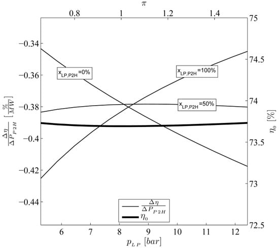
Figure 4.
Total round trip efficiency without electrical heating (η0) and P2H-specific changes of total round trip efficiency () related to the first-stage pressure (pLP).
As illustrated by the thick line representing the reference case without an additional electrical heating, a nearly constant total round trip efficiency of 73.7% is visible, and only negligible effects are observed with varying low pressures. Those effects results from temperature- and pressure-dependent material properties in combination with heat losses inside the safety coolers.
Considering the influence of the investigated electrical heat locations, significant effects with varying low pressures are obviously. The results show the lowest reductions in specific total round trip efficiency of −0.34%/MWP2H for the integration location only in the high-pressure stage (xLP,P2H = 0%) at low pressures of 5.3 bar and with an opposed behavior of the integration location only in the low-pressure stage (xLP,P2H = 100%) at high pressures of 12.4 bar. These characteristics are based on increasing pressure spreads inside the HP and LP turbine during the discharging period, respectively, resulting in a higher exergetic utilization of the electrical heat. In contrast, a different behavior is visible for the integration option in both pressure stages with uniform power distribution (xLP,P2H = 50%). Here, the benefits regarding higher exergetic utilization with adapted pressures in the first stage are equalized through electrical heating power distribution, leading to a nearly constant loss of specific round trip efficiency of −0.38%/MWP2H.
With respect to the lowest specific losses in round trip efficiency with additional electrical heating, the results indicate, as integration location, only the low- or high-pressure range with adapted pressure levels in the first stage. To investigate the potential of cost reduction, specific results related to the cyclic stored air mass—as a relevant parameter for cavern and compressor size—as well as the thermal storage density for both options are illustrated.
Figure 5 shows the resulting cyclic stored air mass as well as its specific reduction with varying pressure in the first stage for the investigated three integration options.
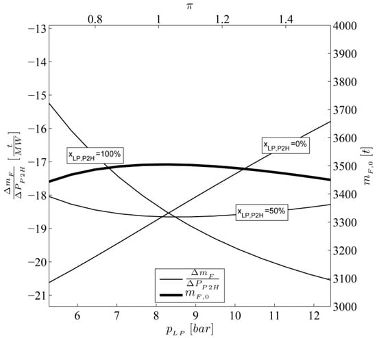
Figure 5.
Stored air mass without electrical heating (mF,0) and P2H-specific changes of stored air mass () related to the first-stage pressure (pLP).
Comparable with the mentioned results regarding the total round trip efficiency, a comparatively constant required air mass of 3450 t is needed for the reference case. Similar to Figure 4, the highest specific reductions in cyclic stored air mass of −15.3 t/MW will be achieved with integration locations only in the low- (xLP,P2H = 100%) and in the high-pressure range (xLP,P2H = 0%), respectively, with simultaneous pressure adaptions in the first stage. According to the defined boundary conditions and specifications, the specific reductions in cyclic storage mass correspond to smaller cavern and compressors sizes of up to −0.5 MWCompressor/MWP2H.
In addition, further potentials in cost reduction are linked to electrical heating. These are shown in Figure 6 with varying low pressures related to both thermal energy storage options: left for the TES option in the first stage, and right for the TES option in the second stage.
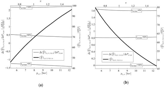
Figure 6.
Thermal storage densities without electrical heating (a—; b—) and P2H-specific changes of thermal storage densities (a—; b—) related to the first-stage pressure (pLP).
Concerning the reference case without additional electrical heating, indicated by the thick lines, higher thermal storage densities are visible with increasing low pressure levels for the LP-TES (Figure 6 left) and with decreasing low pressure levels for the HP-TES (Figure 6 right). Both result from higher compression outlet temperatures leading to a higher temperature spread inside the sensible storage media.
With a further temperature elevation due to electrical heating, different effects on specific thermal storage density for both TES options are visible, mainly influenced by the P2H integration locations. For electrical heating location only in the low-pressure stage (xLP,P2H = 100%), an additional increased specific thermal storage density of 2.3 kWh/m3/MWP2H is reached inside the LP-TES (Figure 6 left), whereas no effects occur inside the HP-TES (Figure 6 right) due to the integrated safety cooler. In contrast, with increasing share of electrical heating inside the high-pressure stage, higher specific thermal storage densities of up to 1.65 kWh/m3/MWP2H are achieved in the HP-TES, but with simultaneous lower increasing specific thermal storage densities in the LP-TES. Actually, regarding the limit case of pure electrical heating in the high-pressure stage (xLP,P2H = 0%), negative specific thermal storage densities of –1.3 kWh/m3/MWP2H are visible inside the LP-TES (Figure 6 left). This behavior is caused by electrical heating inside the HP-TES during the charging period, leading consequenly to increased HP-turbine outlet temperatures during the discharging period and, thus, to decreasing temperature spreads inside the LP-TES. This drawback prohibits cost reductions for all components, in spite of the additional achieved specific reductions of the HP-TES heat exchanger size of up to −18 kW/K/MWP2H.
Additionally, restrictions occur for the permitted electrical heating power in the high-pressure location to fulfil the requirements of maximum operation temperature of 400 °C for the liquid storage medium. These operational limitations are illustrated in Figure 7 for the investigated pressure range inside the first stage.
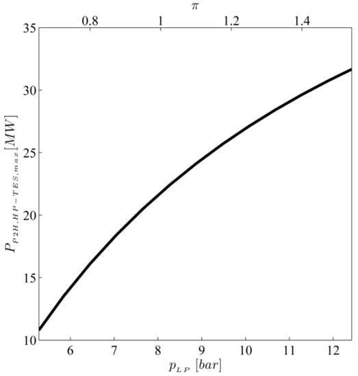
Figure 7.
Maximum permitted electrical heating power in the high-pressure stage (PP2H,HP-TES,max) related to the first-stage pressure (pLP).
As can be seen, higher maximum electrical heating powers (PP2H,HP-TES,max) are feasible in the HP-TES with increasing low pressure levels. This results from decreasing pressure ratios between the first and second stage, accompanied by lower HP compressor outlet temperatures.
On the basis of the presented effects, the results strongly suggest that the electrical heating system must be located in the first pressure stage to allow significant cost reduction potentials for all components without drawbacks inside the cyclic operation. Additionally, in order to minimize the specific losses in total round trip efficiency through the P2H option, the pressure level in the first stage must be chosen as high as possible. With this background, an alternative concept is elaborated, offering an efficient P2H utilization and further cost reduction potentials.
4.3. Alternative Concept
In contrast to the previous system configuration, the alternative concept is based only on one thermal energy storage system (Figure 1c). Here, the heat during compression in the low-pressure stage—additionally elevated by the P2H element—is stored in the regenerator-based heat storage and cooled down during compression in the second stage. Differing from the previous concept, the temperature of the pressurized air leaving the cavern during the discharging mode is elevated by the stored heat via a heat exchanger and expanded over the whole pressure range to ambient conditions.
Here, to prevent freezing problems during the discharging period inside the turbine, a minimum of electrical heating power (PP2H,min) is required. Despite the associated losses in round trip efficiencies caused by the exiting compression heat in the second stage, high exergetic utilizations are feasible due to the large discharging pressure ratio, as well as cost reductions due to the missing thermal energy storage system in the high-pressure range.
According to the defined boundary conditions and specifications in Section 4.2, variation studies related to the low-pressure levels (pLP) are conducted and evaluated with regard to total round trip efficiency and P2H specific results (Figure 8). To prevent freezing problems, the pressure-dependent total round trip efficiencies η are calculated iteratively to determine the minimum electrical heating power leading to turbine outlet temperatures at ambient condition. The simulation results are based on the regenerator model described in Section 3.1, which is extended by the NTU model for the heat exchanger. Similar to the previous concept, the thermal storage efficiencies concerning the LP-TES and the heat exchanger are set to a value of 90 %.
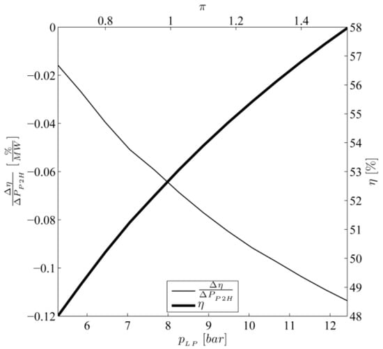
Figure 8.
Total round trip efficiency at minimum of electrical heating power (η) and P2H-specific changes of efficiency () related to the first-stage pressure (pLP) during compression.
As illustrated in Figure 8, increasing total round trip efficiencies results in higher pressure levels in the first stage due to the associated decreasing high-pressure compression ratio and, thus, lower heat losses via the aftercooler. Considering the defined specifications and the maximum compressor outlet temperatures of 350 °C, maximum total round trip efficiencies of 58% are achieved. Comparing these characteristics with the results in Section 4.2, significant lower efficiencies are reached. Although improvements in total round trip efficiency are feasible up to 5% through a two-stage high pressure compression with internal cooling, distinct differences with respect to the adiabatic CAES case remain.
In spite of this characteristic, advantages of the electrical heating are visible. Compared with the previously mentioned concept, significant lower P2H specific losses in total round trip efficiency (Δη/ΔPP2H) occur, showing an opposed behavior with increasing low-pressure levels. This effect is based on a pressure-dependent thermodynamic change in the state of the heat-transfer fluid: with a fixed elevation of enthalpy through the P2H option, higher temperature differences are achieved at low pressure levels, leading to higher turbine outlet powers during discharging at the defined high pressure. This behavior shapes the characteristics of the P2H-specific losses in total round trip efficiency.
In spite of this behavior, highly efficient exergetic P2H utilization is achieved with the alternative concept compared with the previously mentioned concept. Further results regarding the component sizes and the minimum electrical heating power to prevent freezing problems are summarized in Table 3 and Table 4 for a first-stage compression pressure of 12.4 bar.
Table 3.
Central results for the alternative concept at minimum electrical heating power.
Table 4.
Heating specific results for the alternative concept.
Concerning the significant higher cost reduction potentials, the low complexity, and the efficient P2H utilization, the alternative system can be treated in spite of the lower total round trip efficiencies as a base for upgrading the existing CAES power plants and for modifying operational concepts.
4.4. Concept Comparison
For a systematic comparison of the concepts under investigation, the central results regarding the total round trip efficiencies and component sizes are summarized in Table 5 and Table 6. Each of the solution represents the best configuration (Table 5) with respect to total round trip efficiency and the related P2H specific results (Table 6).
Table 5.
Central results related to the maximum total round trip efficiency for TES efficiencies of 90%.
Table 6.
P2H specific results related to the data in Table 5.
The summarized results show that efficient P2H integrations in the extended concept are located in the first pressure stage (xLP,P2H = 100%). Here, higher volumetric thermal storage densities are reached (Table 5) due to the adequate solid media material properties, and no negative systemic drawbacks ar exist (Table 6) leading to decreasing P2H-specific thermal storage densities. Additionally, high electric heating powers are feasible because of the high-temperature-suitable solid material. Comparing the extended with the alternative concept, further improvements in thermal storage density as well as in heat exchanger size are visible, especially regarding the P2H specific results, but on a lower level of total round trip efficiency. In spite of this behavior, the alternative system can be considered as an upgrading solution for conventional CAES power plants to increase flexibility and to reduce fossil combustion.
5. Conclusions
With the further increase of renewable energies costs, flexible and large-scale electricity storage capacities are needed, allowing an increase of volatilities disposability and the participation in different markets. Adiabatic compressed air energy storage power plants extended by P2H options offer high potentials to fulfill the ambitious requirements for costs and flexibility.
Based on an original two-stage A-CAES system, studies considering large variations related to thermal energy storage efficiencies, electrical heating location, power, as well as central process variables, were conducted and evaluated in order to identify suitable solutions with high potential of cost reduction and moderate losses in round trip efficiency. The results show clearly that the electrical heating system must be located in the first pressure stage to allow significant cost reduction potentials for all components without drawbacks inside the cyclic operation. Simultaneously, the pressure level in the first stage must be chosen as high as possible in order to minimize the specific losses in total round trip efficiency through the electrical heating option. On the basis of these aspects, an alternative concept was elaborated offering, at lower total round trip efficiencies, highly efficient exergetic utilization and additional cost reductions, which can be treated as a novel base for upgrading the existing CAES power plants. On the basis of the assumed large-scale specifications, P2H-dependent results for both systems were obtained, allowing the identification of promising configurations, with adequate cost models und considering revenues.
Further benefits can be provided by adaptations in the thermal energy storage efficiencies, but this requires an overall techno-economic optimization. Additionally, detailed development studies were done in order to elaborate design concepts regarding the P2H option coupled with the regenerator-based thermal energy storage inside the low-pressure stage. Promising technologies for the case with high charging powers of up to 20 MWP2H are available (inductive and conductive procedures) but need to be adapted for A-CAES applications.
Author Contributions
Conceptualization: V.D., S.B.; Methodology: V.D., S.B.; Software: V.D.; Investigation: V.D.; Writing—original draft preparation: V.D.
Funding
This research received no external funding.
Conflicts of Interest
The authors declare no conflict of interest.
References
- Vazques, S.; Lukic, S.; Galvan, E.; Franquelo, L. Energy Storage Systems for Transport and Grid Applications. IEEE Trans. Ind. Electron. 2010, 57, 3881–3895. [Google Scholar] [CrossRef]
- Rehman, S.; Al-Hadhrami, L.M.; Alam, M.M. Pumped hydro energy storage system: A technological review. Renew. Sustain. Energy Rev. 2015, 44, 586–598. [Google Scholar] [CrossRef]
- Barbour, E.; Wilson, I.G.; Radcliffe, J.; Ding, Y.; Li, Y.A. review of pumped hydro energy storage development in significant international electricity markets. Renew. Sustain. Energy Rev. 2016, 61, 421–432. [Google Scholar] [CrossRef]
- Zhang, Y.; Yang, K.; Li, X.; Xu, J. The thermodynamic effect of thermal energy storage on compressed air energy storage system. Renew. Energy 2013, 50, 227–235. [Google Scholar] [CrossRef]
- Lund, H.; Salgi, G. The role of compressed air energy storage (CAES) in future sustainable energy systems. Energy Convers. Manag. 2009, 50, 1172–1179. [Google Scholar] [CrossRef]
- Najjar, Y.S.; Zaamout, M.S. Performance analysis of compressed air energy storage (CAES) plant for dry regions. Energy Convers. Manag. 1998, 39, 1503–1511. [Google Scholar] [CrossRef]
- Liu, J.L.; Wang, J.H. A comparative research of two adiabatic compressed air energy storage systems. Energy Convers. Manag. 2016, 108, 566–578. [Google Scholar] [CrossRef]
- Crotogino, F.; Mohmeyer, K.U.; Scharf, R. Huntorf CAES: More than 20 Years of Successful Operation. In Proceedings of the SMRI Spring Meeting, Orlando, FL, USA, 15–18 April 2001. [Google Scholar]
- Holden, P.; Moen, D.; DeCorso, M.; Howard, J. Alabama Electric Cooperative Compressed Air Energy Storage (CAES) Plant Improvements. In Proceedings of the ASME Turbo Expo 2000: Power for Land, Sea, and Air, Munich, Germany, 8–11 May 2000. [Google Scholar] [CrossRef]
- Benato, A.; Stoppato, A. Pumped Thermal Electricity Storage: A technology overview. Therm. Sci. Eng. Prog. 2018, 6, 301–315. [Google Scholar] [CrossRef]
- De Sisternes, F.J.; Jenkins, J.D.; Botterud, A. The Value of Energy Storage in Decarbonizing the Electricity Sector. Appl. Energy 2016, 175, 368–379. [Google Scholar] [CrossRef]
- Dunn, B.; Kamath, H.; Tarascon, J.M. Electrical energy storage for the grid: A battery of choices. Science 2011, 334, 928–935. [Google Scholar] [CrossRef]
- Benato, A.; Stoppato, A. Energy and cost analysis of a new packed bed pumped thermal electricity unit. J. Energy Resour. Technol. 2017, 140, 020904. [Google Scholar] [CrossRef]
- Klumpp, F. Comparison of pumped hydro, hydrogen storage and compressed air energy storage for integrating high shares of renewable energies-potential, cost-comparison and ranking. J. Energy Storage 2016, 8, 119–128. [Google Scholar] [CrossRef]
- Desrues, T.; Ruer, J.; Marty, P.; Fourmigué, J. A thermal energy storage process for large scale electric applications. Appl. Therm. Eng. 2010, 30, 425–432. [Google Scholar] [CrossRef]
- Budt, M.; Wolf, D.; Span, R.; Yan, J.A. review on compressed air energy storage: Basic principles, past milestones and recent developments. Appl. Energy 2016, 170, 250–268. [Google Scholar] [CrossRef]
- Zunft, S.; Dreissigacker, V.; Bieber, M.; Banach, A.; Klabunde, C.; Warweg, O. Electricity storage with adiabatic compressed air energy storage: Results of the BMWi-project ADELE-ING. In Proceedings of the International ETG Congress, Bonn, Germany, 28–29 November 2017; pp. 1–5. [Google Scholar]
- Stöver, B.; Rehfeldt, S.; Alekseev, A.; Stiller, C. Fluessigluftenergiespeicherung: Konzept und Analyse eines Systems fuer großtechnische Anwendungen. In Proceedings of the 45th Kraftwerkstechnisches Kolloquium, Dresden, Germany, 15–16 October 2013; pp. 315–320. [Google Scholar]
- Benato, A. Performance and cost evaluation of an innovative pumped thermal electricity storage power system. Energy 2017, 138, 419–436. [Google Scholar] [CrossRef]
- Thess, A. Thermodynamic efficiency of pumped heat electricity storage. Phys. Rev. Lett. 2013, 111, 110602. [Google Scholar] [CrossRef]
- Houssainy, S.; Janbozorgi, M.; Ip, P.; Kavehpour, P. Thermodynamic analysis of a high temperature hybrid compressed air energy storage (HTH-CAES) system. Renew. Energy 2018, 115, 1043–1054. [Google Scholar] [CrossRef]
- Abarr, M.; Geels, B.; Hertzberg, J.; Montoya, L.D. Pumped thermal energy storage and bottoming system part A: Concept and model. Energy 2017, 120, 320–331. [Google Scholar] [CrossRef]
- Ni, F.; Caram, H.S. Analysis of pumped heat electricity storage process using exponential matrix solutions. Appl. Therm. Eng. 2015, 84, 34–44. [Google Scholar] [CrossRef]
- Turner, R.H. High Temperature Thermal Energy Storage; Franklin: Philadelphia, PA, USA, 1978. [Google Scholar]
- Tessier, M.J.; Floros, M.C.; Bouzidi, L.; Narine, S.S. Exergy analysis of an adiabatic compressed air energy storage system using a cascade of phase change materials. Energy 2016, 106, 528–534. [Google Scholar] [CrossRef]
- Zhao, P.; Dai, Y.; Wang, J. Performance assessment and optimization of a combined heat and power system based on compressed air energy storage system and humid air turbine cycle. Energy Convers. Manag. 2015, 103, 562–572. [Google Scholar] [CrossRef]
- Lv, S.; He, W.; Zhang, A.; Li, G.; Luo, B.; Liu, X. Modelling and analysis of a novel compressed air energy storage system for trigeneration based on electrical energy peak load shifting. Energy Convers. Manag. 2017, 135, 394–401. [Google Scholar] [CrossRef]
- Sustainx. Isothermal CAES Technology. Available online: http://www.sustainx.com/technologyisothermal-caes.htm (accessed on 14 March 2015).
- Castellani, B.; Presciutti, A.; Filipponi, M.; Nicolini, A.; Rossi, F. Experimental investigation on the effect of phase change materials on compressed air expansion in CAES plants. Sustainability 2015, 7, 9773–9786. [Google Scholar] [CrossRef]
- Kim, Y.M.; Lee, J.H.; Kim, S.J.; Favrat, D. Potential and evolution of compressed air energy storage: Energy and exergy analyses. Entropy 2012, 14, 1501–1521. [Google Scholar] [CrossRef]
- Grazzini, G.; Milazzo, A. Thermodynamic analysis of CAES/TES systems for renewable energy plants. Renew. Energy 2008, 33, 1998–2006. [Google Scholar] [CrossRef]
- Grazzini, G.; Milazzo, A. A thermodynamic analysis of multistage adiabatic CAES. Proc. IEEE 2012, 100, 461–472. [Google Scholar] [CrossRef]
- Wolf, D.; Budt, M. LTA-CAES—A low-temperature approach to adiabatic compressed air energy storage. Appl. Energy 2014, 125, 158–164. [Google Scholar] [CrossRef]
- Zunft, S.; Krüger, M.; Dreißigacker, V.; Belik, S.; Hahn, J.; Knödler, P. ADELE-ING: Engineering-Vorhaben fuer die Errichtung der Ersten Demonstrationsanlage zur Adiabaten Druckluftspeichertechnik: Oeffentlicher Schlussbericht; Ed. Züblin AG: Stuttgart, Germany, 2017. [Google Scholar] [CrossRef]
- Dreißigacker, V. Power-to-heat in adiabatic compressed air energy storage power plants for cost reduction and increased flexibility. Heat Mass Transf. 2018, 54, 955–962. [Google Scholar] [CrossRef]
- Lucía, O.; Maussion, P.; Dede, E.J.; Burdío, J.M. Induction Heating Technology and Its Applications: Past Developments, Current Technology, and Future Challenges. IEEE Trans. Ind. Electron. 2014, 61, 2509–2520. [Google Scholar] [CrossRef]
- Sterner, M.; Stadler, I. Energiespeicher. Bedarf, Technologien, Integration; Springer: Berlin/Heidelberg, Germany, 2014. [Google Scholar]
- Belik, S. Numerical modelling of an induction heating process for packed rods with adjacent airflow. In Proceedings of the International Congress on Electrotechnologies for Material Processing, Hannover, Germany, 6–9 June 2017. [Google Scholar]
- Ismail, K.A.R.; Stuginsky, R. A parametric study on possible fixed bed models for pcm and sensible heat storage. Appl. Therm. Eng. 1999, 19, 757–788. [Google Scholar] [CrossRef]
- Hausen, H. Wärmeübertragung im Gegenstrom, Gleichstrom und Kreuzstrom; Springer: Berlin/Heidelberg, Germany, 1950. [Google Scholar]
- Schmidt, F.W.; Willmott, A.J. Thermal Energy Storage and Regeneration; McGraw-Hill Book Company: Washington, DC, USA, 1981. [Google Scholar]
- Gnielinski, V. Berechnung des Waerme- und Stoffaustauschs in durchstroemten ruhenden Schuettungen. Verfahrenstechnik 1982, 16, 36–39. [Google Scholar]
- Martin, H. Wärmeübertrager; Thieme: Stuttgart, Germany; New York, NY, USA, 1988. [Google Scholar]
- Shah, K.R.; Sekulic, D.P. Fundamentals of Heat Exchanger Design; John Wiley & Sons: Hoboken, NJ, USA, 2003; ISBN 0-471-32171-0. [Google Scholar]
- RWE. ADELE—Adiabatic Compressed-Air Energy Storage (CAES) for Electricity Supply. Available online: http://www.rwe.com (accessed on 14 March 2015).
© 2019 by the authors. Licensee MDPI, Basel, Switzerland. This article is an open access article distributed under the terms and conditions of the Creative Commons Attribution (CC BY) license (http://creativecommons.org/licenses/by/4.0/).