Experimental and Numerical Investigation of Resonance Characteristics of Novel Pumping Element Driven by Two Piezoelectric Bimorphs


Abstract
:Featured Application
Abstract
1. Introduction
2. Specimens and Experiment Setup
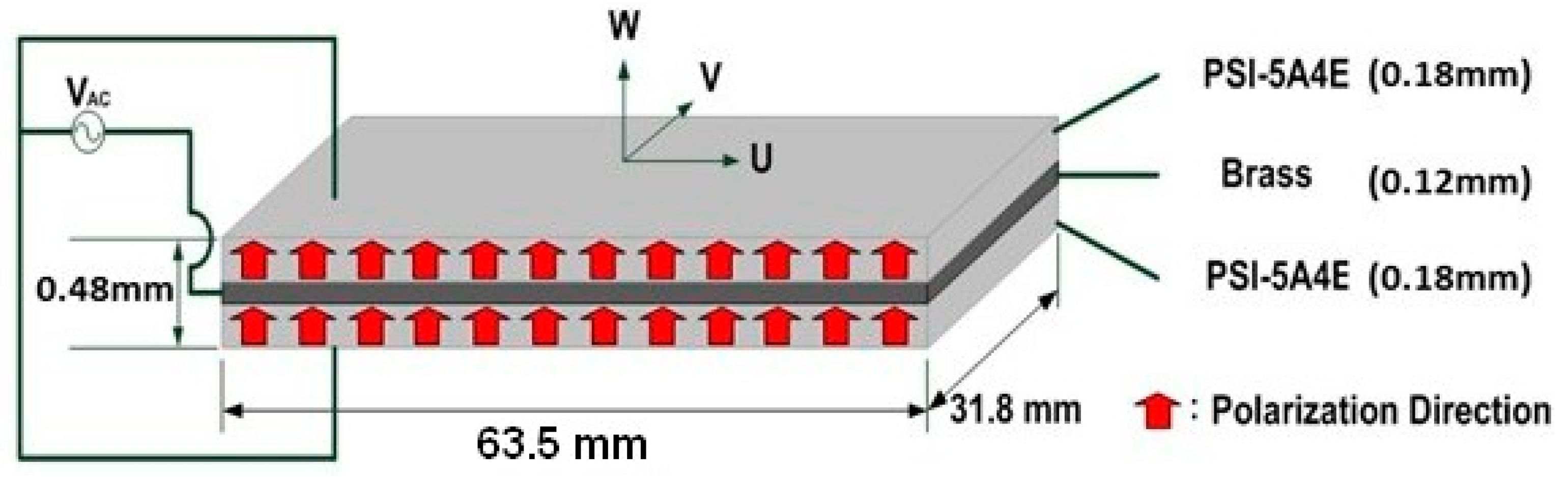
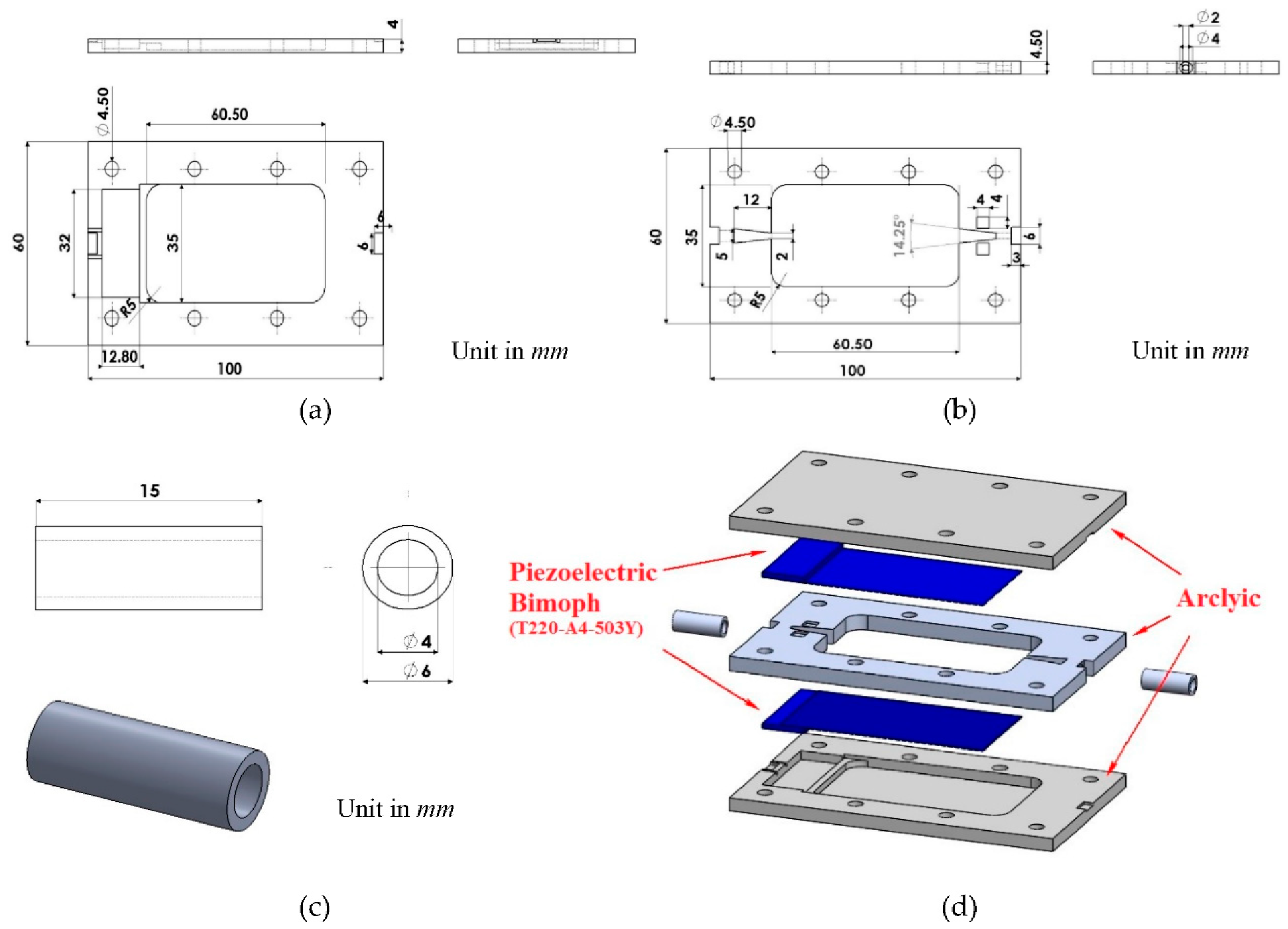
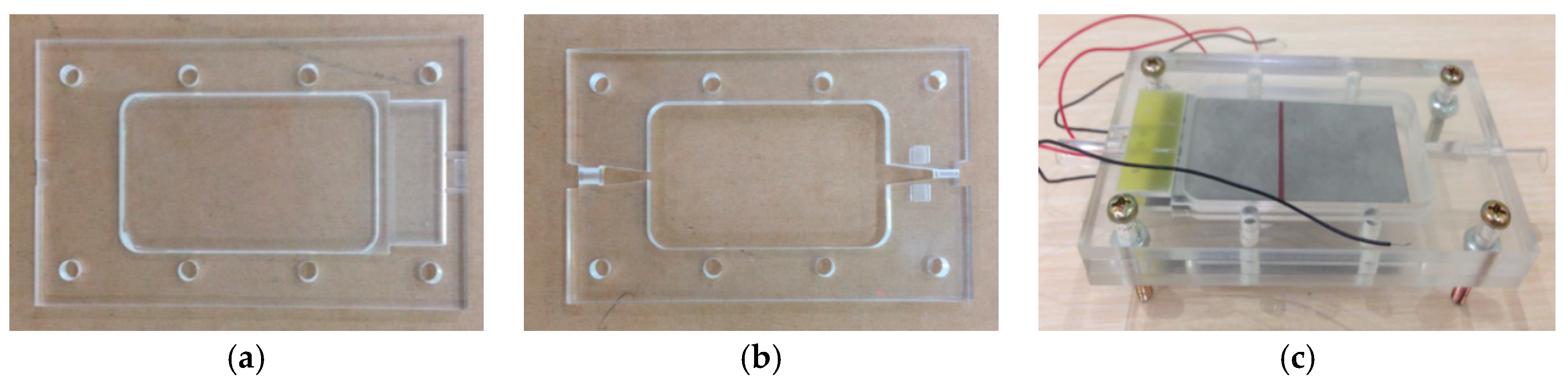
2.1. Materials and Specimens
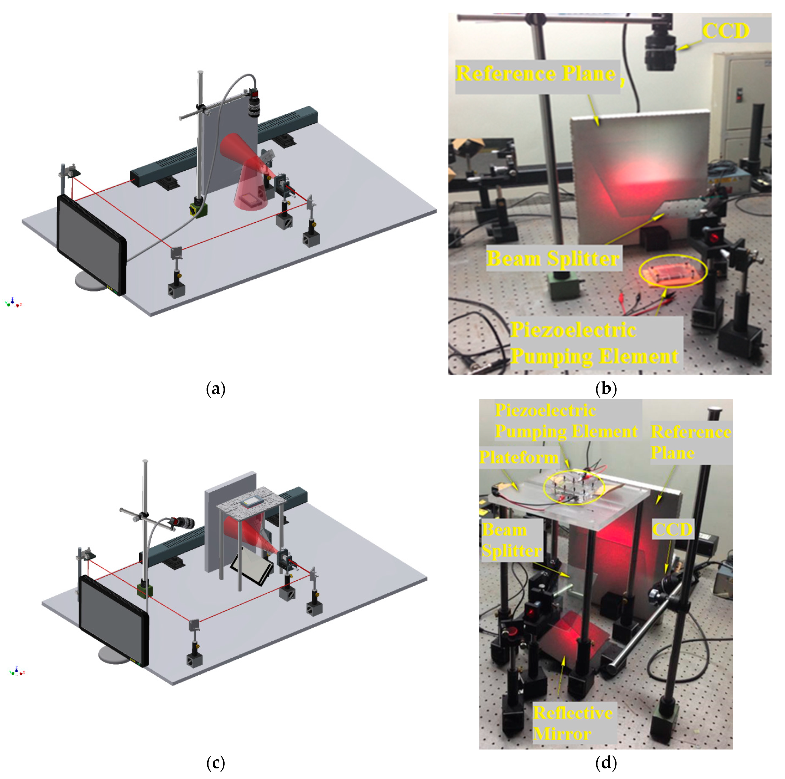
2.2. Amplitude-Fluctuation Electronic Speckle Pattern Interferometry (AF-ESPI)
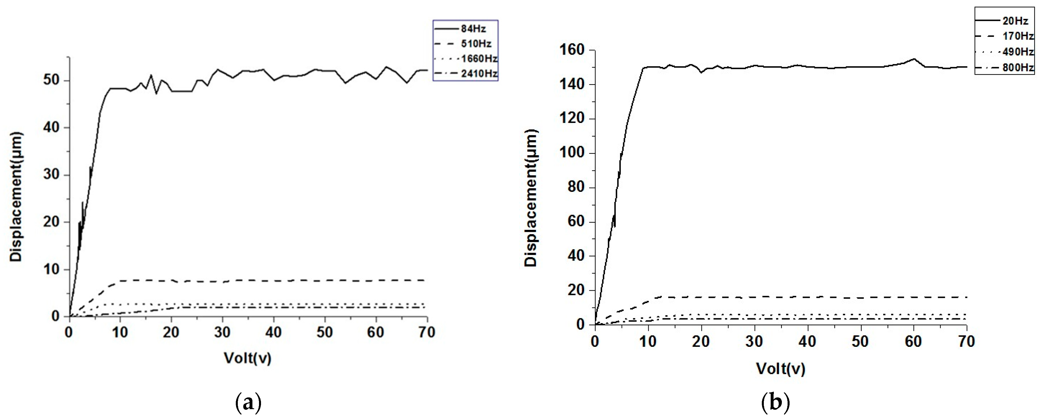
2.3. Laser Doppler Vibrometer (LDV)
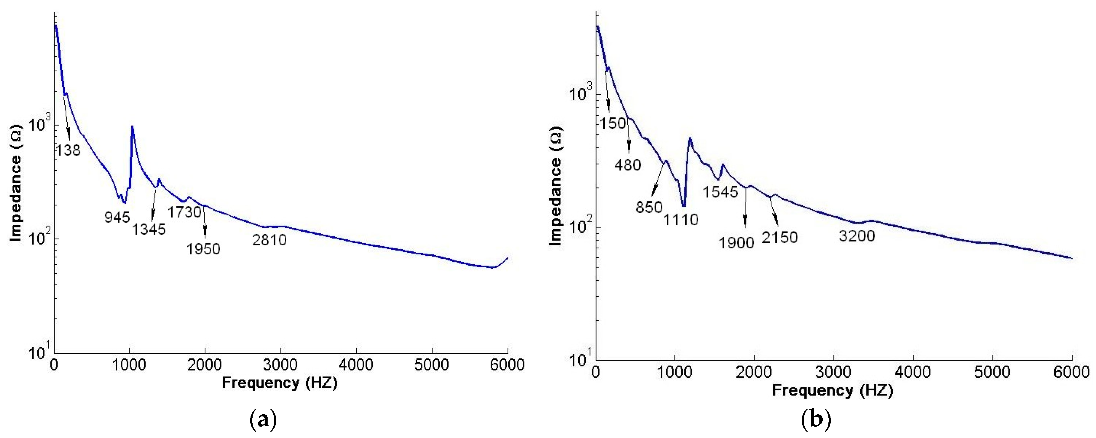
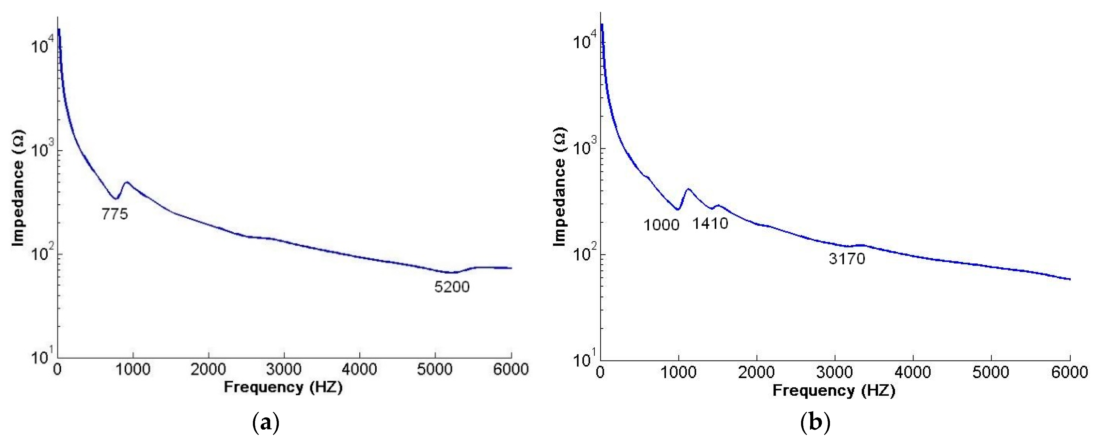
2.4. Impedance Analysis
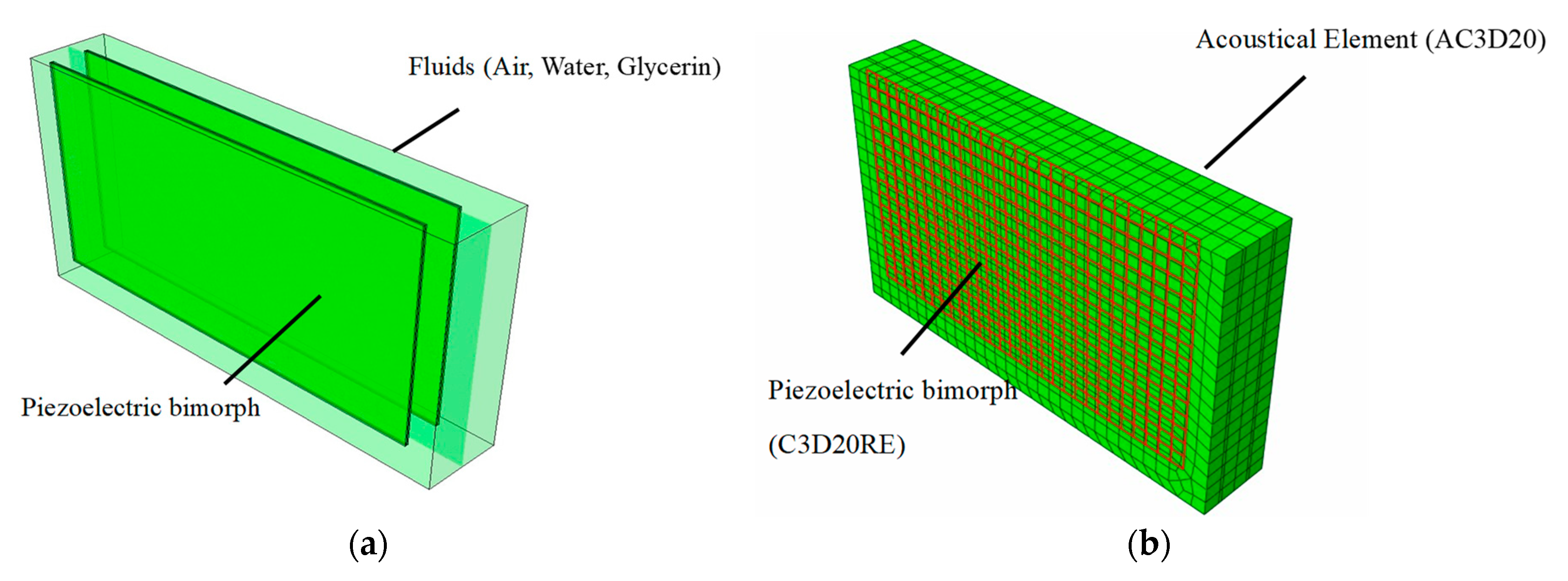
2.5. Finite Element Analysis
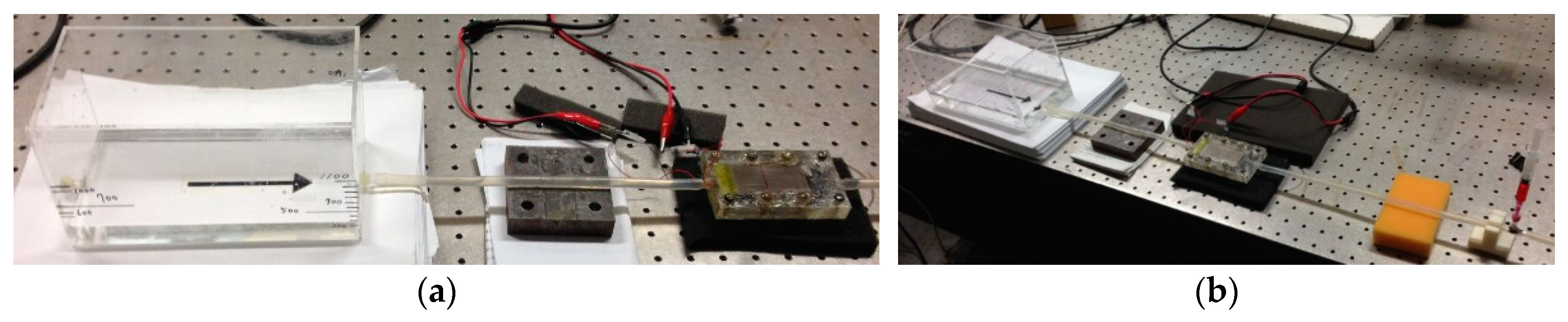
2.6. The Flow Rate and Flow Velocity Measurement
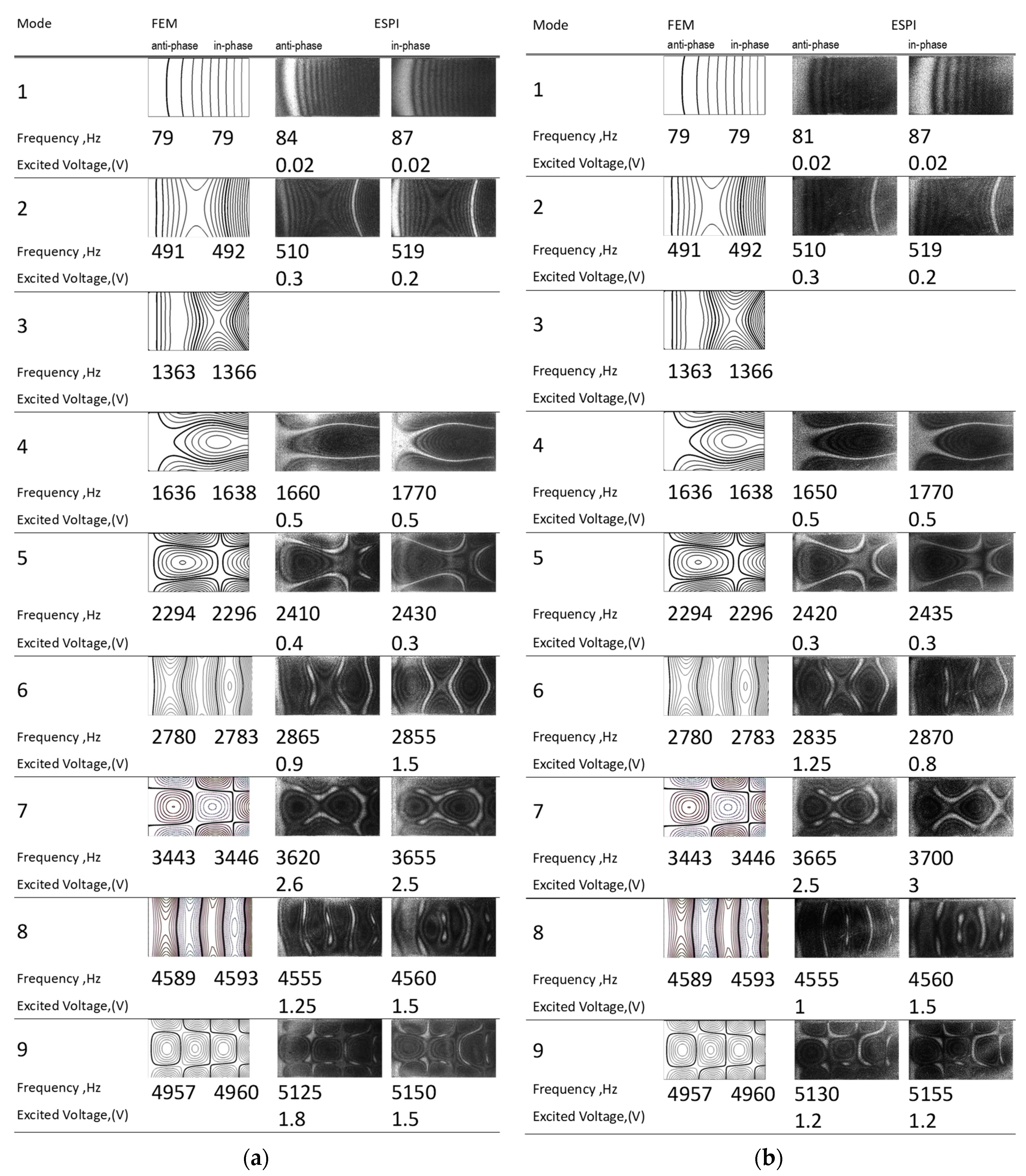
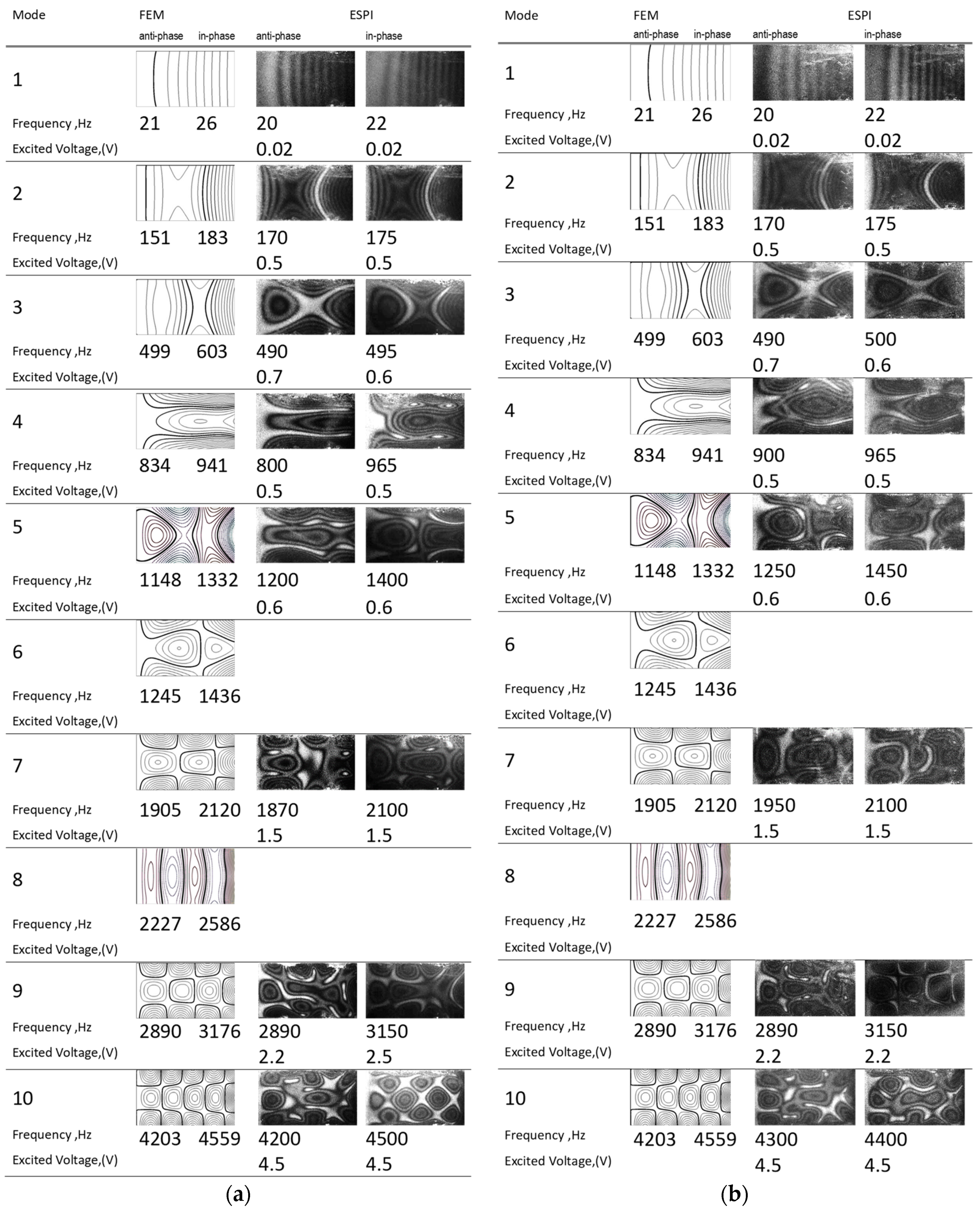
3. Experimental and Numerical Results
4. Conclusions
Author Contributions
Funding
Acknowledgments
Conflicts of Interest
References
- Tiersten, H.F. Linear Piezoelectric Plate Vibrations; Plenum: New York, NY, USA, 1969. [Google Scholar]
- Tzou, H.S. Piezoelectric Shells: Distributed Sensing and Control of Continua; Kluwer Academic Publishers: Dordrecht, The Netherlands, 1993. [Google Scholar]
- Kunkel, H.A.; Locke, S.; Pikeroen, B. Finite-element analysis of vibrational modes in piezoelectric ceramics disks. IEEE Trans. Ultrason. Ferroelectr. Freq. Control 1990, 37, 316–328. [Google Scholar] [CrossRef] [PubMed]
- Guo, N.; Cawley, P.; Hitchings, D. The finite element analysis of the vibration characteristics of piezoelectric discs. J. Sound Vibr. 1992, 159, 115–138. [Google Scholar] [CrossRef]
- Ivina, N.F. Numerical analysis of the normal modes of circular piezoelectric plates of finite dimensions. Sov. Phys. Acoust. 1990, 35, 385–388. [Google Scholar]
- Wu, J.; Lu, L. Liquid-solid coupled system of micropump. Acta Mech. Solida Sin. 2006, 19, 40–49. [Google Scholar] [CrossRef]
- de Lima, C.R.; Vatanabe, S.L.; Choi, A.; Nakasone, P.H.; Pires, R.F.; Silva, C.N.E. A biomimetic piezoelectric pump: Computational and experimental characterization. Sens. Actuators A 2009, 152, 110–118. [Google Scholar] [CrossRef]
- Zhou, Y.; Amirouche, F. Study of fluid damping effects on resonant frequency of an electromagnetically actuated valveless micropump. Int. J. Adv. Manuf. Technol. 2009, 45, 1187–1196. [Google Scholar] [CrossRef]
- Hou, W.; Das, B.; Jiang, Y.; Quin, S.; Zheng, X.I.; Pi, X.; Yang, J.; Liu, H.G.; Zeng, J.; Zeng, Z.G. Simulation of the Diaphragm Properties of a PZT-based Valveless Micropump. In Proceedings of the 3rd IEEE International Conference on Nano/Micro Engineered and Molecular Systems, Sanya, China, 6–9 January 2008; pp. 449–452. [Google Scholar]
- Ma, H.K.; Hou, B.R.; Wu, H.Y.; Lim, C.Y.; Gao, J.J.; Kou, M.C. Development and application of a diaphragm micro-pump with piezoelectric device. Microsyst. Technol. 2008, 14, 1001–1007. [Google Scholar] [CrossRef]
- Ma, H.K.; Chen, B.R.; Gao, J.J.; Lim, C.Y. Development of an OAPCP-micropump liquid cooling system in a laptop. Int. Commun. Heat. Mass. Transf. 2009, 36, 225–232. [Google Scholar] [CrossRef]
- Ma, H.K.; Su, H.C.; Wu, J.Y. Study of an innovative one-sided actuating piezoelectric valveless micropump with a secondary chamber. Sens. Actuators A 2001, 171, 297–305. [Google Scholar] [CrossRef]
- Huang, C.H.; Ma, C.C. Vibration characteristics for piezoelectric cylinders using amplitude-fluctuation electronic speckle pattern interferometry. AIAA J. 1998, 36, 2262–2268. [Google Scholar] [CrossRef]
- Huang, Y.; Zhang, J.H.; Hu, X.Q.; Xia, Q.X.; Huang, W.Q. Dynamics Analysis and Flow Rate Experiments on the Fish-Tailing Type of Valveless Piezoelectric Pump with RECTANGULAR vibrator. In Proceedings of the 2nd International Conference on Industrial Mechatronics and Automation, Wuhan, China, 30–31 May 2010; pp. 1127–1131. [Google Scholar]
- Singh, S.; Kumar, N.; George, D.; Sen, A.K. Analytical modeling, simulations and experimental studies of a PZT actuated planar valveless PDMS micropump. Sens. Actuators A 2015, 225, 81–94. [Google Scholar] [CrossRef]
- Ma, C.C.; Huang, C.H. The investigation of three-dimensional vibration for piezoelectric rectangular parallelepipeds using the AF-ESPI method. IEEE Trans. Ultrason. Ferroelectr. Freq. Control 2001, 48, 142–153. [Google Scholar] [PubMed]
- Huang, C.H.; Lin, Y.C.; Ma, C.C. Theoretical analysis and experimental measurement for resonant vibration of piezoceramic circular plates. IEEE Trans. Ultrason. Ferroelectr. Freq. Control 2004, 51, 12–24. [Google Scholar] [CrossRef] [PubMed]
- Huang, C.H.; Ma, C.C.; Lin, Y.C. Theoretical, numerical, and experimental investigation on resonant vibrations of piezoceramic annular disks. IEEE Trans. Ultrason. Ferroelectr. Freq. Control 2005, 52, 1204–1216. [Google Scholar] [CrossRef] [PubMed]
- Lin, Y.C.; Ma, C.C. Resonant vibration of piezoceramic plates in fluid. Interact. Multiscale Mech. 2008, 1, 177–190. [Google Scholar] [CrossRef]
- Simulia. ABAQUS. Version 6.13 Documentation; Dassault Systémes Simulia Corp.: Providence, RI, USA, 2013. [Google Scholar]
- Zhou, S.W.; Liang, C.; Rogers, C.A. An impedance-based system modeling approach for induced strain actuator-driven structures. J. Vib. Acoust. Trans. ASME 1996, 118, 323–331. [Google Scholar] [CrossRef]
- Bhalla, S.; Soh, C.K. Structural health monitoring by piezo-impedance transducers I: Modelling. J. Aerosp. Eng. 2004, 17, 154–165. [Google Scholar] [CrossRef]
- Bhalla, S.; Soh, C.K. Structural health monitoring by piezo-impedance transducers II: Applications. J. Aerosp. Eng. 2004, 17, 166–175. [Google Scholar] [CrossRef]
- Huang, Y.H.; Ma, C.C. Experimental and numerical investigations of vibration characteristics for parallel-type and series-type triple-layered piezoceramic bimorphs. IEEE Trans. Ultrason. Ferroelectr. Freq. Control 2009, 56, 2598–2611. [Google Scholar] [CrossRef] [PubMed]
- Huang, Y.H.; Hsu, H.T. Solid–liquid coupled vibration characteristics of piezoelectric hydroacoustic devices. Sens. Actuators A 2016, 238, 177–195. [Google Scholar] [CrossRef]


| Material Properties | Structural Plate (Brass) | Piezoelectric Plate (PZT) |
|---|---|---|
| Model Name | Bronze C86100 | PSI 5A4E |
| Density | 8830 kg/m3 | 7800 kg/m3 |
| Young′s Modulus | 1.03 × 10¹¹ Pa | x-direction- 6.6 × 10¹⁰ Pa y-direction- 6.6 × 10¹⁰ Pa z-direction- 5.2 × 10¹⁰ Pa |
| Poisson′s Ratio | 0.34 | x-direction- 0.31 y-direction- 0.242 z-direction- 0.242 |
| Piezoelectric Constants | - | d15 = 550 pm/V d31 = -190 pm/V d33 = 390 pm/V |
| Dielectric Constants | - | εS11 = 11.12 nF/m εS33 = 14.02 nF/m |
| Material Constants | Air | Water | Glycerine |
|---|---|---|---|
| Bulk Modulus | 1.42 | 2.2 | 4.39 |
| Density | 1.2 Kg/ | 1000 Kg/ | 1260 Kg/ |
| Wave Velocity | 344 m/s | 1483 m/s | 1875 m/s |
| Viscosity | 0.00001 Pa·s | 0.001 Pa·s | 1.2 Pa·s |
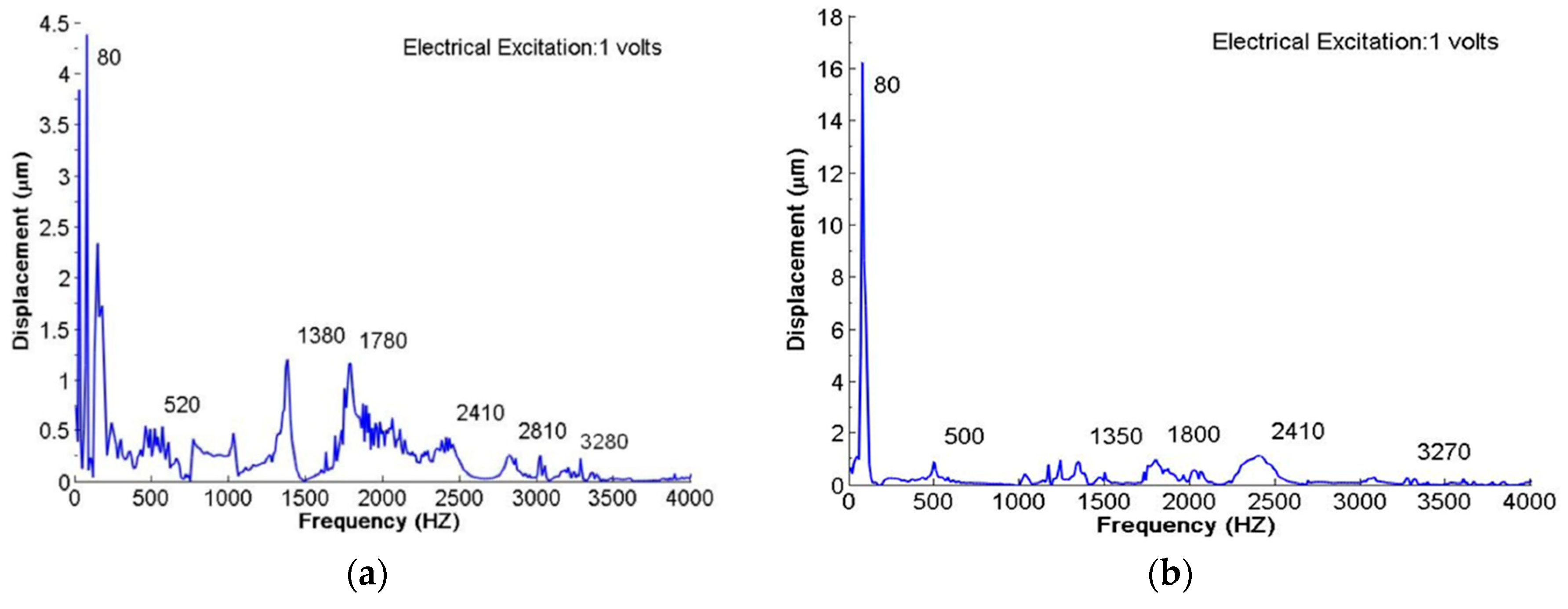
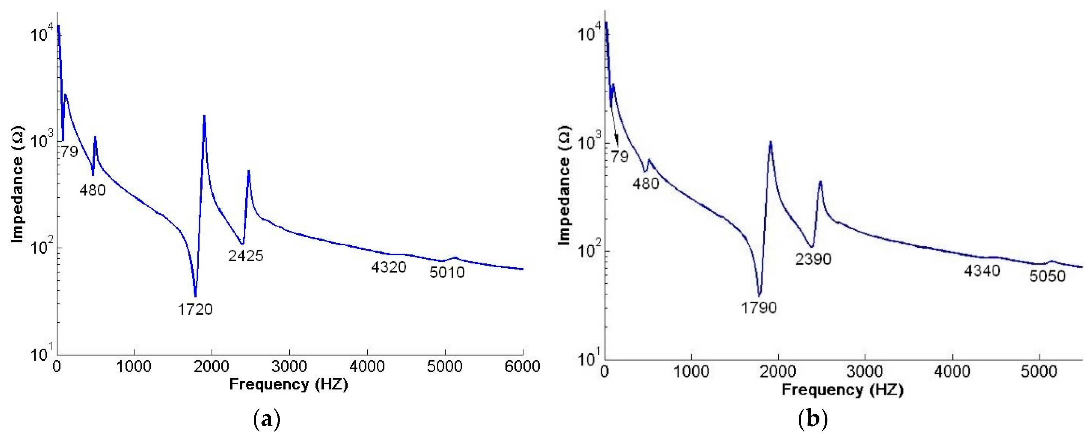
| Mode | FEM (Hz) | AF-ESPI (HZ) | Difference (%) | LDV (Hz) | Difference (%) | Impedance (Hz) | Difference (%) | |
|---|---|---|---|---|---|---|---|---|
| 1 | Anti-phase | 79 | 84 | 6.33 | 80 | 1.27 | 79 | 0 |
| In-phase | 79 | 87 | 10.13 | 80 | 1.27 | |||
| 2 | Anti-phase | 491 | 510 | 3.87 | 520 | 5.91 | 480 | −2.24 |
| In-phase | 492 | 519 | 5.49 | 500 | 1.63 | 470 | −4.47 | |
| 3 | Anti-phase | 1363 | 1380 | 1.25 | ||||
| In-phase | 1366 | 1350 | −1.17 | |||||
| 4 | Anti-phase | 1636 | 1660 | 1.47 | 1780 | 8.80 | 1720 | 5.13 |
| In-phase | 1638 | 1770 | 8.06 | 1800 | 9.89 | 1790 | 9.28 | |
| 5 | Anti-phase | 2294 | 2410 | 5.06 | 2410 | 5.06 | 2425 | 0.62 |
| In-phase | 2296 | 2430 | 5.84 | 2410 | 4.97 | 2390 | −1.67 | |
| 6 | Anti-phase | 2780 | 2865 | 3.06 | 2810 | 1.08 | ||
| In-phase | 2783 | 2855 | 2.59 | |||||
| 7 | Anti-phase | 3443 | 3620 | 5.14 | 3280 | −4.73 | ||
| In-phase | 3446 | 3655 | 6.07 | 3270 | −5.11 | |||
| 8 | Anti-phase | 4589 | 4555 | −0.74 | 4320 | −5.44 | ||
| In-phase | 4593 | 4560 | −0.72 | 4340 | −5.07 | |||
| 9 | Anti-phase | 4957 | 5125 | 3.39 | 5010 | −2.29 | ||
| In-phase | 4960 | 5150 | 3.83 | 5050 | −1.98 | |||
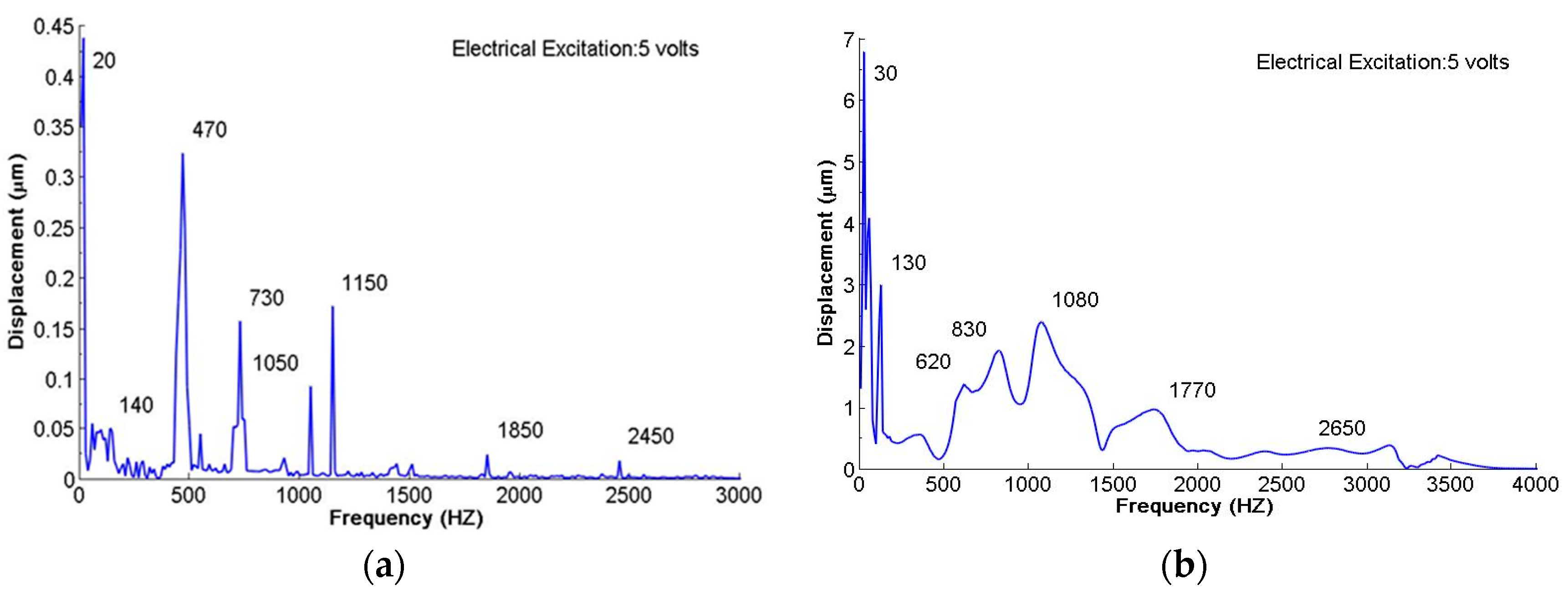
| Mode | FEM (Hz) | AF-ESPI (HZ) | Difference (%) | LDV (Hz) | Difference (%) | Impedance (Hz) | Difference (%) | |
|---|---|---|---|---|---|---|---|---|
| 1 | Anti-phase | 21 | 20 | −4.76 | 20 | −4.76 | ||
| In-phase | 26 | 22 | −15.38 | 20 | −23.08 | |||
| 2 | Anti-phase | 151 | 170 | 12.58 | 140 | −7.28 | 138 | −8.61 |
| In-phase | 183 | 175 | −4.37 | 150 | −18.03 | 150 | −18.03 | |
| 3 | Anti-phase | 499 | 490 | −1.80 | 420 | −15.83 | ||
| In-phase | 603 | 495 | −17.91 | 430 | −28.69 | 480 | −20.40 | |
| 4 | Anti-phase | 834 | 800 | −4.08 | 890 | 6.71 | 945 | 13.31 |
| In-phase | 941 | 965 | 2.55 | 920 | −2.23 | 1110 | 17.96 | |
| 5 | Anti-phase | 1148 | 1200 | 4.53 | 1290 | 12.37 | 1345 | 17.16 |
| In-phase | 1332 | 1400 | 5.11 | 1380 | 3.60 | 1545 | 15.99 | |
| 6 | Anti-phase | 1245 | ||||||
| In-phase | 1436 | |||||||
| 7 | Anti-phase | 1905 | 1870 | −1.84 | 2030 | 6.56 | 1950 | 2.36 |
| In-phase | 2120 | 2100 | −0.94 | 2060 | −2.83 | 2150 | 1.42 | |
| 8 | Anti-phase | 2227 | ||||||
| In-phase | 2586 | |||||||
| 9 | Anti-phase | 2890 | 2890 | 0.00 | 2980 | 3.11 | 2810 | −2.77 |
| In-phase | 3176 | 3150 | −0.82 | 3150 | −0.82 | 3200 | 0.76 | |
| 10 | Anti-phase | 4203 | 4200 | −0.07 | ||||
| In-phase | 4559 | 4500 | −1.29 | |||||
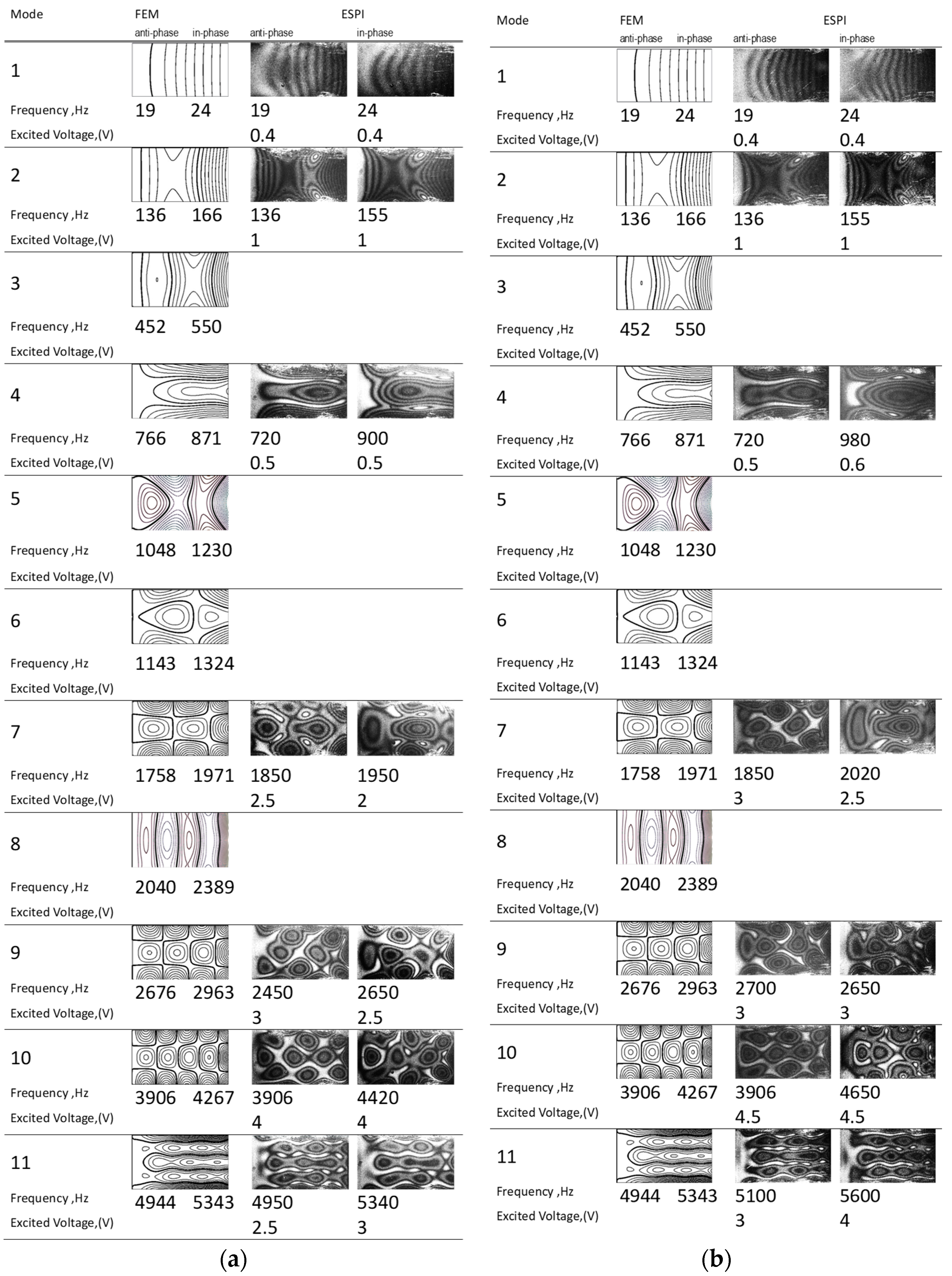
| Mode | FEM (Hz) | AF-ESPI (HZ) | Difference (%) | LDV (Hz) | Difference (%) | Impedance (Hz) | Difference (%) | |
|---|---|---|---|---|---|---|---|---|
| 1 | Anti-phase | 19 | 19 | 0 | 20 | 5.26 | ||
| In-phase | 24 | 24 | 0.00 | 30 | 25.00 | |||
| 2 | Anti-phase | 136 | 136 | 0.00 | 140 | 2.94 | ||
| In-phase | 166 | 155 | −6.63 | 130 | −21.69 | |||
| 3 | Anti-phase | 452 | 470 | 3.98 | ||||
| In-phase | 550 | 620 | 12.73 | |||||
| 4 | Anti-phase | 766 | 720 | −6.01 | 730 | −4.70 | 775 | 1.17 |
| In-phase | 871 | 900 | 3.33 | 830 | −4.71 | 1000 | 14.81 | |
| 5 | Anti-phase | 1048 | 1050 | 0.19 | ||||
| In-phase | 1230 | 1080 | −12.20 | |||||
| 6 | Anti-phase | 1143 | 1150 | 0.61 | ||||
| In-phase | 1324 | |||||||
| 7 | Anti-phase | 1758 | 1850 | 5.23 | 1850 | 5.23 | ||
| In-phase | 1971 | 1950 | −1.07 | 1770 | −10.20 | |||
| 8 | Anti-phase | 2040 | ||||||
| In-phase | 2389 | |||||||
| 9 | Anti-phase | 2676 | 2450 | −8.45 | 2450 | −8.45 | ||
| In-phase | 2963 | 2650 | −10.56 | 2650 | −10.56 | 3170 | 6.99 | |
| 10 | Anti-phase | 3906 | 3906 | 0.00 | ||||
| In-phase | 4267 | 4420 | 3.59 | |||||
| 11 | Anti-phase | 4944 | 4950 | 0.12 | 5200 | 5.18 | ||
| In-phase | 5343 | 5340 | −0.06 | |||||
| Frequency Voltage | 1 min (µL/s) | 2 min (µL/s) | 3 min (µL/s) | Average Flow Rate (µL/s) | Increment (µL/s) | Gain |
|---|---|---|---|---|---|---|
| (a) anti-phase motion | ||||||
| 20 Hz | 3450 | 3458.3 | 3466.6 | 3458.3 | 75 | 2.22% |
| 170 Hz | 3513.3 | 3531.7 | 3445 | 3496.7 | 113.4 | 3.35% |
| 490 Hz | 3405 | 3473.3 | 3443.3 | 3440 | 56.7 | 1.68% |
| 800 Hz | 3428.3 | 3433.3 | 3353.3 | 3405 | 21.7 | 0.64% |
| 1250 Hz | 3421.6 | 3403.3 | 3438.3 | 3421.6 | 38.3 | 1.13% |
| 1870 Hz | 3410 | 3320.3 | 3450 | 3393.4 | 10 | 0.3% |
| 2890 Hz | 3401.7 | 3391.7 | 3381.7 | 3391.7 | 8.4 | 0.25% |
| 4200 Hz | 3406.7 | 3373.3 | 3390 | 3385.3 | 2 | 0.06 |
| (b) in-phase motion | ||||||
| 20 Hz | 3206.6 | 3178.3 | 3240 | 3226.7 | −156.6 | −4.63% |
| 170 Hz | 3405 | 3393.3 | 3443.3 | 3413.3 | 30 | 0.88% |
| 490 Hz | 3338.3 | 3396.6 | 3220 | 3318.3 | −65 | −1.92% |
| Frequency Voltage | Time (s) | Average Velocity (cm/s) | Increment of Velocity (cm/s) |
|---|---|---|---|
| (a) anti-phase motion | |||
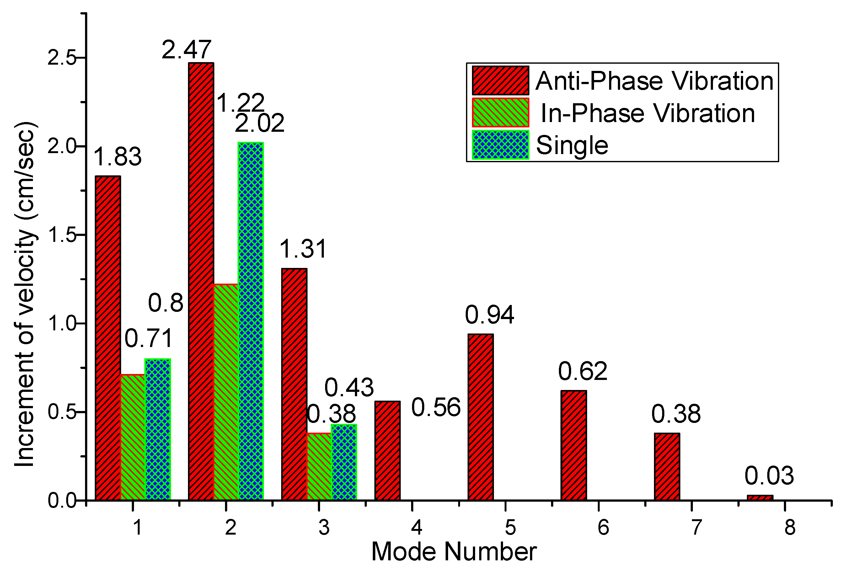
| 20 Hz | 5.21 | 11.99 | 1.83 |
| 170 Hz | 4.95 | 12.63 | 2.47 |
| 490 Hz | 5.45 | 11.47 | 1.31 |
| 800 Hz | 5.83 | 10.72 | 0.56 |
| 1250 Hz | 5.63 | 11.10 | 0.94 |
| 1870 Hz | 5.8 | 10.78 | 0.62 |
| 2890 Hz | 5.93 | 10.54 | 0.38 |
| 4200 Hz | 6.03 | 10.19 | 0.03 |
| (b) in-phase motion | |||
| 20 Hz | 5.75 | 10.87 | 0.71 |
| 170 Hz | 5.49 | 11.38 | 1.22 |
| 490 Hz | 5.93 | 10.54 | 0.38 |
| Frequency Voltage | Time (s) | Average Velocity (cm/s) | Increment of Velocity (cm/s) |
|---|---|---|---|
| 20 Hz | 5.7 | 10.96 | 0.8 |
| 170 Hz | 5.13 | 12.18 | 2.02 |
| 490 Hz | 5.9 | 10.59 | 0.43 |
© 2019 by the authors. Licensee MDPI, Basel, Switzerland. This article is an open access article distributed under the terms and conditions of the Creative Commons Attribution (CC BY) license (http://creativecommons.org/licenses/by/4.0/).
Share and Cite
Lin, Y.-C.; Huang, Y.-H.; Chu, K.-W. Experimental and Numerical Investigation of Resonance Characteristics of Novel Pumping Element Driven by Two Piezoelectric Bimorphs. Appl. Sci. 2019, 9, 1234. https://doi.org/10.3390/app9061234
Lin Y-C, Huang Y-H, Chu K-W. Experimental and Numerical Investigation of Resonance Characteristics of Novel Pumping Element Driven by Two Piezoelectric Bimorphs. Applied Sciences. 2019; 9(6):1234. https://doi.org/10.3390/app9061234
Chicago/Turabian StyleLin, Yu-Chih, Yu-Hsi Huang, and Kwen-Wei Chu. 2019. "Experimental and Numerical Investigation of Resonance Characteristics of Novel Pumping Element Driven by Two Piezoelectric Bimorphs" Applied Sciences 9, no. 6: 1234. https://doi.org/10.3390/app9061234
APA StyleLin, Y.-C., Huang, Y.-H., & Chu, K.-W. (2019). Experimental and Numerical Investigation of Resonance Characteristics of Novel Pumping Element Driven by Two Piezoelectric Bimorphs. Applied Sciences, 9(6), 1234. https://doi.org/10.3390/app9061234