Article

A New Hybrid Reciprocating Compressor Model Coupled with Acoustic FEM Characterization and Gas Dynamics

1
College of Electromechanical Engineering, Qingdao University of Science and Technology, Qingdao 266061, China
2
College of Chemical Engineering, Qingdao University of Science and Technology, Qingdao 266042, China
3
College of Chemical Engineering and Environment, China University of Petroleum, Beijing 102249, China
*
Author to whom correspondence should be addressed.
Appl. Sci. 2019, 9(6), 1179; https://doi.org/10.3390/app9061179
Submission received: 5 March 2019 / Revised: 16 March 2019 / Accepted: 17 March 2019 / Published: 20 March 2019
(This article belongs to the Section Energy Science and Technology)

Abstract

:
Accurate comprehension of thermodynamic demeanor and pressure pulsation propagation is of great attractiveness in a reciprocating compressor system. To consider the reciprocal interaction between compressor and pipelines, a hybrid numerical model is thus built by coupling the in-cylinder lumped parameter approach, in-pipe 1D gas dynamics and 3D acoustic characteristics of chambers. The transmission and reflection coefficients of a geometrically complex chamber are achieved by the definition of an acoustic characterization method based on acoustic FEM simulation data, with a high level of accuracy. Numerical results of this new hybrid model are compared with predictions from the traditional hybrid model with in-pipe 1D gas dynamics, together with experimental data. Through comparison analysis, the advantages are highlighted in using the acoustic FEM characterization for complex elements since the new model performs numerical solution without introducing any simplifications to the geometry of fluid domain.

1. Introduction

Energy demands in developing countries such as South Africa, India, Brazil and China have marked a sharp increase based on the statistical data among 69 countries [1]. To be conclusive, most energy supply rooting from fossil fuels is the main energy consumption characteristic in these countries. On one hand, currently improper energy structure should be improved by increasing application of renewable energy such as wind, solar and biomass; on the other hand, techniques should be developed to enhance the overall energy efficiency.
One possible way to improve energy efficiency is optimizing the working performance and reliability of reciprocating compressor since it is an important component in many industries such as refrigeration systems, petrochemical plants and civil applications, and has a significant role among the total energy consumption. Particular attention should be paid to the enhancement of thermodynamic efficiency and the control of pressure pulsation which may induce local noise and piping vibration. In this view, contribution of a well-tuned numerical model in the preliminary design process is unquestionable for evaluating the compressor performance and preventing its matching mistakes. The developed model must preserve the accuracy to meet the engineering demands without damaging the computational cost.
Reciprocating compressor models based on 3D computational fluid dynamics (CFD) give the most detailed characterization of performance without simplifying complex geometries. Aigner [2] investigated valve motion and internal flow inside compression chamber by employing simplified effective flow area within the valve flow and force. Kim et al. [3] applied 3D compressible Reynolds-averaged numerical model to examine the compressor flow and acoustic behavior of a suction muffler. Wang et al. [4] presented an examination on the delayed colure of the suction valve in a reciprocating refrigerator compressor by varying the rotational speed and valve parameters. Although most account of compressor complex geometries is taken, the 3D CFD model cannot be suitable for specific goals especially in the preliminary design phase due to the unacceptable computational cost.
The lumped parameter models being the simplified ones give results efficiently and describe the compressor performance globally. Damle et al. [5] reported a simulation model to predict thermodynamic values and energy consumption of the compressor during the compression phase. Considering leakages and frictions, Yang et al. [6] established a comprehensive numerical model to analyze the thermodynamic performance of a semi-hermetic CO2 reciprocating compressor. Liu et al. [7] examined the effects of key valve parameters on the performance of a trans-critical refrigeration compressor. Farzaneh-Gord et al. [8] numerically analyzed the effects of natural gas compositions on thermodynamic process and it was demonstrated that natural gas with lower molar weight consumes more power per cycle than natural gas with higher molar weight. Tuhovcak et al. [9] compared various integral correlations of heat transfer inside the cylinder for different compressor settings and fluids. The lumped parameter models which in-cylinder conditions are predicted by resolving energy and mass equations of cylinder control volume; however, poorly account for the reciprocal interaction between compressor and the connected pipelines.
In an attempt to handle the limitations of lumped parameter models, a few linear hybrid models have emerged in the literature which couple the acoustic description of pipelines to the lumped parameter approach. Elson and Soedel [10] reported the importance of examining pulsation effects on the thermodynamic process of reciprocating compressor with a hybrid model by using acoustic wave theory. The acoustic characteristics of pipelines were represented by four-pole method through combining the simplified acoustic elements such as pipes and volumes. Zhou et al. [11] conducted an iteration scheme to overcome the poor convergence problem of suction pressure. In all the above works the pipeline system were strongly approximated as simple pipe elements and plenum geometries together with additional correction to match experimental results. To model a detailed characterization of complex fluid domain, some authors took advantage of acoustic finite element method (FEM) for geometries with single input and single outlet [12] and geometries with multi-port [13]. However, the linear hybrid models are mainly limited in the event of acoustic resonant response or pressure pulsations with large amplitude [14], especially for variable-speed compression systems due to the impossible whole resonance avoidance.
Numerical calculation of 1D unsteady gas-dynamics is much more appropriate in the analysis of pulsations. Benson et al. [15] applied the Euler method to solve equations of first thermodynamic law and mass conservation for cylinder volume and the Method of Characteristics (MOC) to calculate the second-order hyperbolic non-linear partial differential equations. Xu et al. [16] applied finite disturbance theory and four-pole method to predict pressure pulsations in a reciprocating compressor system and highlighted that the predictions of finite disturbance theory were much more accordance with experimental data than results from acoustic wave theory. Liu and Duan [17] developed a transient gas dynamic mathematical model for the simulation of compressor performance and pressure pulsations, which considered thermodynamics with gas leakage, kinematics, valve dynamics, gas flow through valves and transient unsteady flow in the duct system. Brun et al. [18] revealed that pulsations can be damped by large piping volumes with weak impedances, and conversely amplified by strong impedance systems. In a general conclusion of these first studies, one can deduce that the hybrid model with in-pipe 1D gas dynamics results in great benefits respect to both the levels of accuracy and the computational cost. This up to date case is to model complex fluid domains.
To summarize the aforesaid discussion, a question occurs: a variable-speed reciprocating compressor with multi-port complex plena is how to be modelled with a high level of trade-off between accuracy and computational cost. The previous literature survey demonstrates that few works have answered this question. This work aims to handle with this question through building in detail a new hybrid numerical model which, to the authors’ best knowledge, represents a further step in the compressor modelling. This hybrid model extensively combines the lumped parameter approach, gas dynamics and acoustic FEM characterization. The modeling technique shares the advantages of the existing modelling method previously commented in the sense of mutual interaction between compressor and the pipelines, high level of details for complex fluid domains, large amplitudes of pressure pulsation and low computational cost. To this end, the hybrid model is implemented in commercially available software MATLAB and thermodynamic properties of the working fluid are obtained by calling the NIST REFPROP database [19]. A comparison analysis between this model and the hybrid model with gas dynamics is carried out, together with experimental data.

2. Hybrid Model

The new hybrid numerical model includes three sub-models: (1) reciprocating compressor sub-model which is on the basis of a 0D quasi-steady method; (2) in-pipe gas dynamic sub-model; (3) acoustic FEM characterization of multi-port plena. The following sections describe different features of these sub-models respectively and the corresponding algorithm.

2.1. Reciprocating Compressor Sub-Model

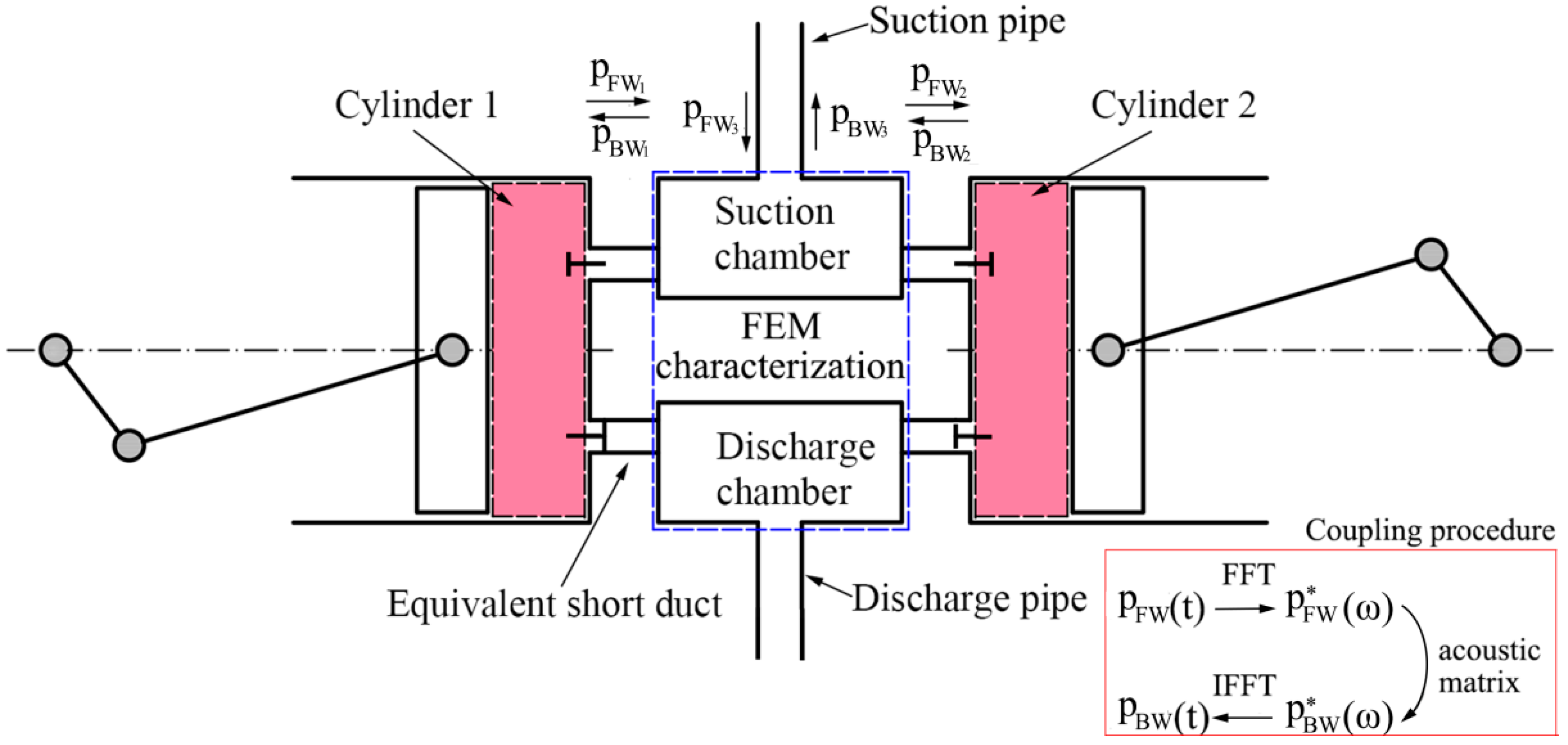
Figure 1 schematically depicts a basic line of reciprocating compressor working unit with spring-loaded suction and discharge valves. The connecting rod converts the rotary motion of crankshaft to the linear movement of piston. In the modelling process, the piston end face, cylinder wall and cylinder cover enclose a varying control volume regulated by the increments of crank-angle. Evaluation of thermodynamic properties is performed by taking advantage of a 0D quasi-steady approach through solving the equations of first thermodynamic law and mass conservation.
The equation of mass conservation in the control volume of Figure 1 is given by [8]:
d m c v d t = d m s d t d m d d t
Mass flow rate through valves can be determined by the following equations which have been successfully and widely used as the standard approach for compressors [8,20]:
d m s d t = { φ s A s 2 ( p s p c v ) ρ s for   p s > p c v ,   y s > 0 φ s A s 2 ( p c v p s ) ρ c v for   p s < p c v ,   y s > 0 d m d d t = { φ d A d 2 ( p c v p d ) ρ c v for   p c v > p d ,   y d > 0 φ d A d 2 ( p d p c v ) ρ d for   p c v < p d ,   y d > 0
Without considering the potential and kinetic energy reasonably, energy balance equation over the control volume based on the first law of thermodynamics is governed as follow:
d Q c v d t + d m s d t h s = d m d d t h d + d d t ( m e ) c v + p c v d V c v d t
With the equation:
d ( m e ) c v d t = m c v d e c v d t + e c v d m c v d t
Equation (3) is re-written as follow:
d e c v d t = 1 m c v [ d Q c v d t p c v d V c v d t + d m s d t h s d m d d t h d e c v d m c v d t ]
in which heat exchange rate is given by the well-known formulation:
d Q c v d t = α A wall ( T wall T c v )
To determine the convective heat transfer coefficient α, the Woschni correlation is used in this paper. It is developed and frequently used for heat transfer studies in IC engines. Also, it has been widely used in reciprocating compressors since, by neglecting the combustion source term, the common peak of the convective coefficient close to a crank angle of 180° is shifted to the end of the compression step as it is expected for reciprocating compressors [8,21]. The equation of heat transfer coefficient is defined as:
α = 3.26 p c v 0.8 T c v 0.546 D c v 0.2 u 0.8
In the above equation, u equals to 6.18up for suction and discharge phases and 2.28up for compression and expansion phases.
The instantaneous in-cylinder working volume from top dead center is:
V c v = V c l + π D p 4 r 1 [ 1 cos ( ω t ) + r 2 r 1 ( 1 1 ( r 1 / r 2 ) 2 sin 2 ( ω t ) ) ]
Reciprocating compressor valves are automatic, i.e., their motion is determined by pressure difference between the cylinder and suction/discharge ambient. Main hypotheses for valve dynamic calculation are: valve is a one-degree-of-freedom system, valve displacement is restricted by limiter and valve plate is rigid. Finally, the resulting equation of valve motion represented by a 2nd ordinary differential form is described by:
m e q d 2 y d t 2 + c e q d y d t + k k e q y = C D A D Δ p + G i n i t
where c e q = 2 ξ k k e q m e q is damping coefficient and is often neglected [9] as its value is usually low and hard to obtain; CD is the drag coefficient which could be obtained from previous investigation [2]; Δ p is pressure difference described by pspcv for suction valve and described by pcvpd for discharge valve; in order to consider the collision impact between the valve plate and valve limiter/seat, a rebound coefficient of 0.3 [22] is introduced here:
( d y d t ) r e b = 0.3 ( d y d t ) i m p

2.2. In-Pipe Gas Dynamic Sub-Model

Gas dynamic models solve the 1D non-homentropic unsteady flow with considering the variation of cross-sectional area, friction and heat transfer processes. Naturally, a non-homogeneous hyperbolic set of the continuity, momentum and energy equations with a much more conservative arrangement is given by the following equations [23]:
U ( x , t ) t + F ( U ) x + B 1 ( U ) + B 2 ( U ) = 0
U ( x , t ) = [ ρ A ρ u A ρ e 0 A ] , F ( U ) = [ ρ u A ( ρ u 2 + p ) A ρ u h 0 A ] B 1 ( U ) = [ 0 p d A d x 0 ] , B 2 ( U ) = [ 0 ρ G f A ρ q A ]
where B1 and B2 are the source term vectors denoting separately the effect of area variation and the effect of heat transfer and friction between gas and wall. Closure of the conservation system is performed by equation of gas properties. Since the hyperbolic system cannot be solved analytically, it could be only computed by recurring to numerical techniques.

2.3. Acoustic FEM Characterization Sub-Model

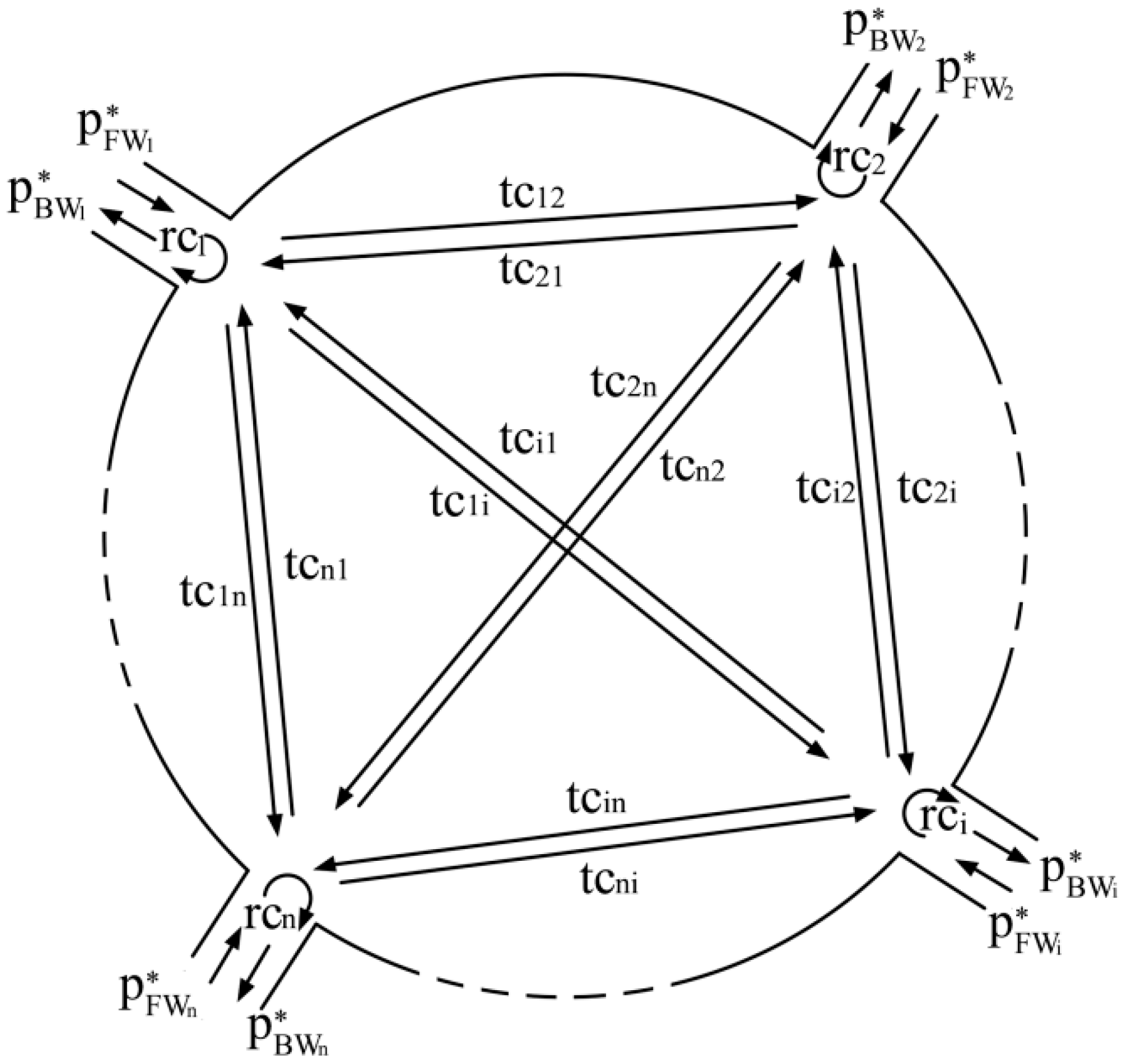
As depicted in Figure 2, a certain fluid domain is described with multiple connecting pipes. In each pipe, pressure wave could be decomposed linearly in a natural way as a forward acoustic pressure wave p F W i * and a backward acoustic pressure wave p B W i * by means of acoustic theory. For the sake of convenience, positive direction denotes the orientation to configuration. As shown in this figure, we may interpret that p F W i * takes information with regard to the flow toward configuration. Conversely, p B W i * carries the resulting effect of the configuration on pressure wave propagation. It is summed up that p B W i * can be expressed in a linear way as a function of p F W i * with correlative transmission and reflection coefficients:
{ p B W 1 * = r c 1 p F W 1 * + t c 21 p F W 2 * + + t c i 1 p F W i * + + t c n 1 p F W n * p B W 2 * = t c 12 p F W 1 * + r c 2 p F W 2 * + + t c i 2 p F W i * + + t c n 2 p F W n * p B W i * = t c 1 i p F W 1 * + t c 2 i p F W 2 * + + r c i p F W i * + + t c n i p F W n * p B W n * = t c 1 n p F W 1 * + t c 2 n p F W 2 * + + t c i n p F W i * + + r c n p F W n *
Here, r c i = p B W i * / p F W i * and t c i j = p B W j * / p F W i * are respectively the reflection and transmission coefficients; p F W i * and p B W i * are the resultant of acoustic pressure p i * and particle velocity u i * :
p F W i * = p i * + Y i u i * 2 , p B W i * = p i * Y i u i * 2
where Y = ρa is acoustic impedance.
To obtain all the transmission and reflection coefficients, n FEM simulations are needed by imposing the incident pressure p F W i * at one boundary and anechoic termination to other boundaries. At i-th simulation, the reflection coefficient rci and transmission coefficient tcij are produced. Equation (13) could be written more clearly in a matrix form:
{ p B W 1 * p B W 2 * p B W i * p B W n * } = [ r c 1 t c 21 t c i 1 t c n 1 t c 12 r c 2 t c i 2 t c n 2 t c 1 i t c 2 i r c i t c n i t c 1 n t c 2 n t c i n r c n ] { p F W 1 * p F W 2 * p F W i * p F W n * }
Acoustic FEM has been extensively employed in compressor field [12,13]. The thereon based 3D Helmholtz equation is given by:
2 p * + σ p * = j ρ ω q f
where 2 = 2 x 2 + 2 y 2 + 2 z 2 is Laplace Operator; σ = ω/a is wave number; j = 1 . When calculating Equation (16), boundary conditions (i.e., acoustic pressure, particle velocity or acoustic impedance) in the fluid domain must be defined firstly. Subsequently, the fluid domain is discretized into finite elements to obtain the matrices of each element respect to acoustic stiffness, acoustic mass and acoustic damping. Finally, the direct-response frequency-analysis procedure can be employed to evaluate each nodal acoustic pressure by solving the total algebraic matrices determined by summarizing each element matrix. The Galerkin weighted residual method is used to transform Equation (16) into finite element equations as:
[ K a + j ω C a ω 2 M a ] p * = F a
in which Ka, Ca and Ma are in sequence the total matrices of acoustic stiffness, acoustic damping and acoustic mass; Fa is the vector of acoustic forces combining the contribution of the boundary conditions and acoustic source vector. We can see from Equation (17) that the acoustic response of geometry is determined only by fluid domain, boundary conditions and fluid state. More in detail, the fluid density and sound speed play a vital role on the fluid state.

2.4. Numerical Procedure

As stated before, the hybrid model consists of the compressor, gas dynamic and acoustic FEM characterization sub-models. The former two sub-models work in the time domain, whereas the last one is in frequency domain. Reciprocal interaction among sub-models is determined by the coupling algorithm, as shown in Figure 3. Moreover, in order to guarantee the implementation of this method, the compressor suction/discharge valve channels are approximately treated as equivalent short ducts (ESDs). The numerical procedure is inspired by the points that the in-pipe pressure perturbation in the way of 1D unsteady flow may be decomposed as a forward pressure component and a backward pressure component [24]:
p F W = p r e f { [ 1 + ( a r e f / a A ) λ ] / 2 } 2 γ / ( γ 1 ) , p B W = p r e f { [ 1 + ( a r e f / a A ) β ] / 2 } 2 γ / ( γ 1 )
where λ and β are given by:
λ = a a r e f + γ 1 2 u a r e f , β = a a r e f γ 1 2 u a r e f ;
and a multi-port complex fluid domain could be well described by the transmission and reflection coefficients through acoustic FEM characterization. Mutual transformation between time domain and frequency domain is obtained by using Fast Fourier Transform (FFT) and its inverse.
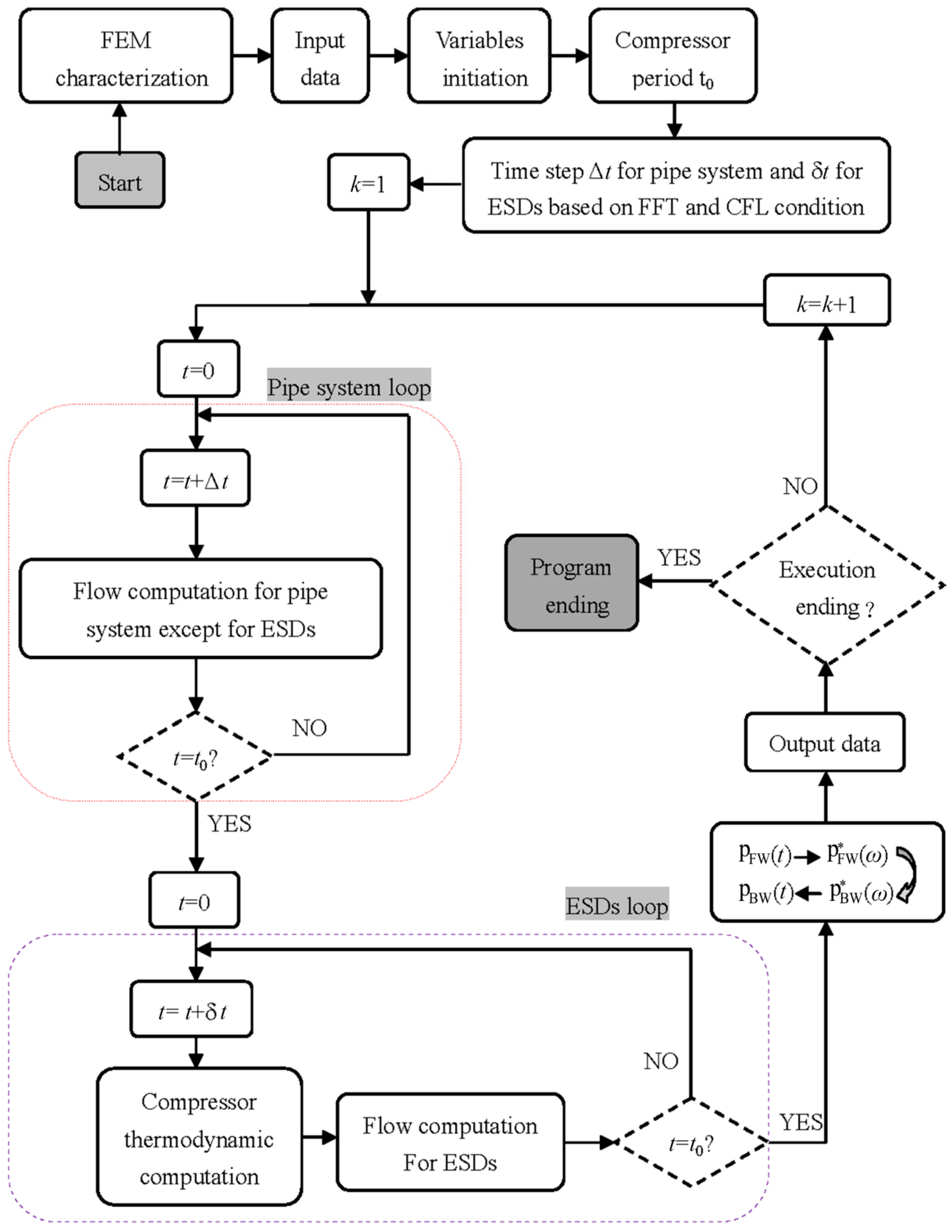
The flowchart of the hybrid approach is shown in Figure 4. The acoustic FEM simulations of complex geometries are first performed based on the approach described in Section 2.3. The obtained acoustic coefficients are then introduced in main procedure. The time steps are determined based on FFT and CFL condition. The flow computation for main pipes are carried out based on the approach described in Section 2.2 for one whole cycle, and then the compressor thermodynamic calculation (Section 2.1) and flow calculation in ESDs are also performed for a whole cycle. Subsequently, the hybrid coupling procedure described in Section 2.4 is carried out. The obtained acoustic boundary will used in next cycle. As coupling of acoustic characterization needs time-domain variables p F W i for a necessarily whole period, the numerical procedure follows a period iterative fashion. The procedure includes three loops totally. The pipe system loop is performed to solve the governing equations in the main pipe and the boundary conditions. Subsequently, the ESDs loop is performed with solution of compressor thermodynamics and the unsteady flow in ESDs. The above two loops are included inside a main loop which regulates the well-running of execution. Also, the main loop calculates the values β i ( k + 1 ) with k + 1 indicating the period-iterative times, which will be imposed in the next period as boundary conditions at the pipe-end connected to the FEM characterized configuration.
Before implementing the loop calculation, it is firstly to perform acoustic FEM simulations of the complex geometries at the given mean thermodynamic conditions in the range of frequencies interested in. The results are processed to determine the transmission and reflection coefficients indexed on wave number concerning to each simulation frequency. The coefficient values will be then interpolated based on multiples of the compressor fundamental frequency for loop calculation. In addition, in order to extend application of the acoustic representation to different thermodynamic conditions, a simple correction that keeps the wave number the same is employed instead of further FEM calculation [24].
The time-step of loop calculation must be properly set. It is common sense that the setup of spatial mesh size Δx is carried out by users with a suitable trade-off between accuracy and computational cost. However, the time interval Δt will be determined by the criterion of Courant-Friedrichs-Lewy applied to each pipe:
Δ t Δ x a + | u |
In addition, the input complex amplitudes p F W i * ( k ) at the k-th period are achieved through transforming the period time history of pressure component p F W i ( k ) by means of FFT algorithm. This transformation is primarily deficient in that the needed values must be equally spaced as an array of 2n (n is an integer), and the first and the last values must be located separately at the beginning and the end of the compressor period. Therefore, time discretization must be performed with a constant value Δ t = t 0 / 2 n (t0 indicates compressor period) and be compatible with Equation (20). It is noteworthy that the equivalent duct is quite short. The common time discretization will highly damage the global computational cost. Therefore, two different time-steps Δt and δt are imposed separately to the pipe system and ESDs. This simple approach is much economical for computational cost to handle with a very fine spatial mesh size in particular ducts.
After the time-steps are determined, the conservation equations in pipes are solved by employing the LW2 numerical scheme [18]. The flow properties at pipe-ends are updated by using the Trapezoidal Method of Characteristics (TMOC) developed by authors [17]. Although the TMOC formulation is developed for ideal gas, it can be applied to real gas model through simply calling the NIST REFPROP database for gas properties [25]. Without increasing complexity and computational effort, the influence of friction and heat transfer is better evaluated on the characteristic lines and the path-line. The boundary conditions applied, except for the one contiguous to the acoustic FEM characterized element, follow the Benson’s quasi-steady physical models [15]. In the ESDs loop, the compressor sub-model is solved by using the standard 4th order Runge–Kutta method. Temperature and density are the two independent thermodynamic properties that are enough to pick out other thermodynamic properties. These computations regulated by respective time-steps run several times for the whole compressor period. Then, the pipe system loop and the ESDs loop finish.
Subsequently, the main loop calculates the values β i ( k + 1 ) that will be imposed, in the next period at each corresponding time-step, as the boundary conditions of the pipes connected to the FEM characterized configuration. The steps are as follows: (1) calculation of time-domain pressure component in the whole k-th period from the results of unsteady flow computation:
p F W i ( k ) = p r e f { [ 1 + ( a r e f / a A i ( k ) ) λ i ( k ) ] / 2 } 2 γ / ( γ 1 )
(2) calculation of p F W i * ( k ) from p F W i ( k ) by using FFT algorithm; (3) calculation of p B W i * ( k + 1 ) from p F W i * ( k ) by means of Equation (15); (4) calculation of p B W i ( k + 1 ) from p B W i * ( k + 1 ) by using the inversion of FFT algorithm; (5) calculation of β i ( k + 1 ) from p B W i ( k + 1 ) based on the equation as follows:
β i ( k + 1 ) = ( a A i ( k + 1 ) / a r e f ) [ 2 ( p B W i ( k + 1 ) / p r e f ) ( γ 1 ) / 2 γ 1 ]
Also, the main loop identifies whether or not the numerical procedure has reached the convergence condition of thermodynamic process and flow properties at the monitor points. If the procedure ending has not been achieved, a new calculation period is carried out. This iterative process works until the procedure ending is obtained.

3. Results and Discussion

This section is focused on evaluation of the developed hybrid model. Two common and representative chamber geometries are examined: (1) geometries with multi ports and (2) geometries with single input and output, consisting of complex internals.

3.1. Case 1: Geometries with Multi Ports

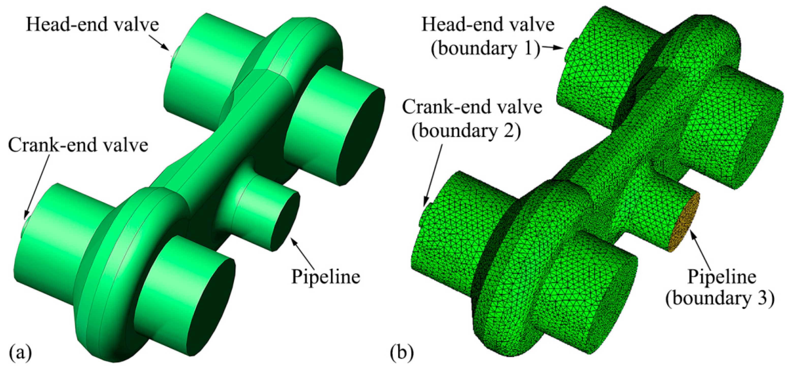
A double-acting reciprocating air compressor is firstly studied, which is equipped with two suction valves and two discharge valves. The suction chamber is geometrically identical with the discharge one and both have three boundaries, as shown in Figure 5. Two of them fit together with the valves and the third one with the pipeline. Geometric properties and thermodynamic conditions of this examined compressor are listed in Table 1. The commercial code VirtualLab is used to perform the acoustic FEM simulations in the scope of frequencies between 1 Hz and 1501 Hz with a step of 10 Hz. The thermodynamic conditions reported in Table 1 are considered. The fluid domain is discretized with the unstructured, tetrahedral elements. The cell size is about 20 times smaller than the minimum wavelength considered [13], which can behave a well balance between accuracy and computational time. For each chamber, three simulations are required. Each simulation is carried out by imposing particle velocity on one boundary and anechoic termination on the others.
By processing numerical results, the transmission and reflection coefficients of each chamber are calculated corresponded to each predefined frequency. For the sake of clarity, only the operations of discharge chamber are shown in Figure 6 when the particle velocity is imposed on the boundary of head-end valve. Moreover, the acoustic coefficients obtained can be extensively applied for different thermodynamic conditions by expressing them as a function of the wavenumber which corresponds to each frequency. This simplest approach needs no further acoustic FEM simulations of the chamber. In addition, the acoustic coefficients are interpolated to obtain the acoustic operations versus the compressor harmonics.
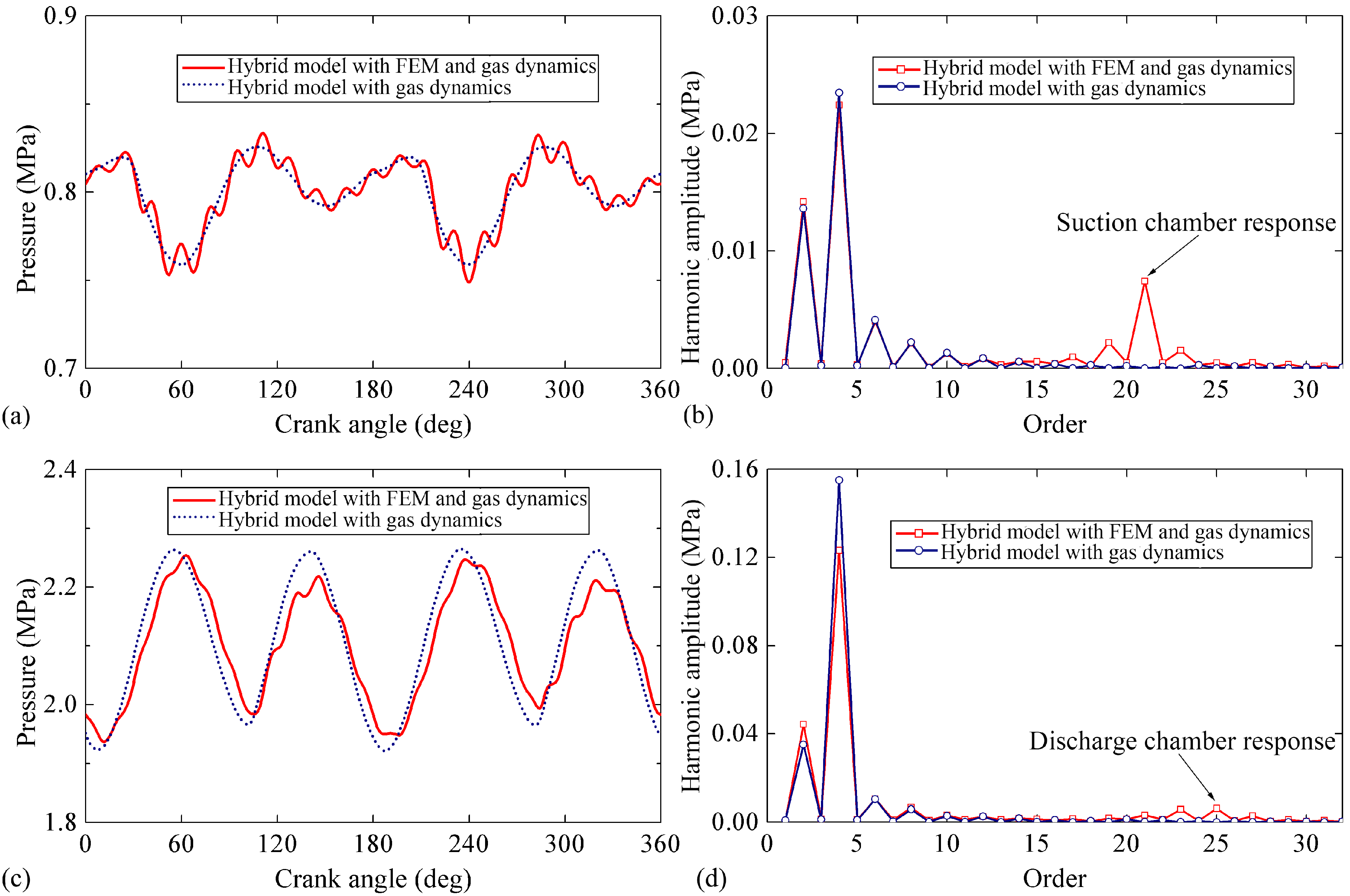
It is worth pointing out that the compressor model with in-pipe 1D gas dynamics has been successfully applied to very simple compression system. A comparison analysis is performed between it and the developed hybrid model with acoustic FEM characterization. Figure 7 shows the comparison of pressure profile and its amplitude-frequency characteristics at the suction and discharge pipe-ends connected to the chamber. Generally, the two models give similar results when an acoustic response is not dominated by chamber. In particular, the attention is focused on the influence of complex geometries on compressor simulation. It can be seen that the model with 1D gas dynamics poorly involves the acoustic response of chamber as it simply considers the chamber as a volume cavity. Conversely, the hybrid model predicts clearly marked acoustic response of the chamber due to the acoustic FEM characterization.
Figure 8 depicts the in-cylinder pressure variation between the two models. The predictions are in good agreement due to the low response of compressor cycle to the pressure pulsation inside pipelines. However, by comparing in detail the thermodynamic cycle at the suction and discharge phase, it is noticed that in-cylinder pressure oscillation trend is directly linked to the pulsating pressure profiles inside the pipeline system.

3.2. Case 2: Geometries with Single Input and Output

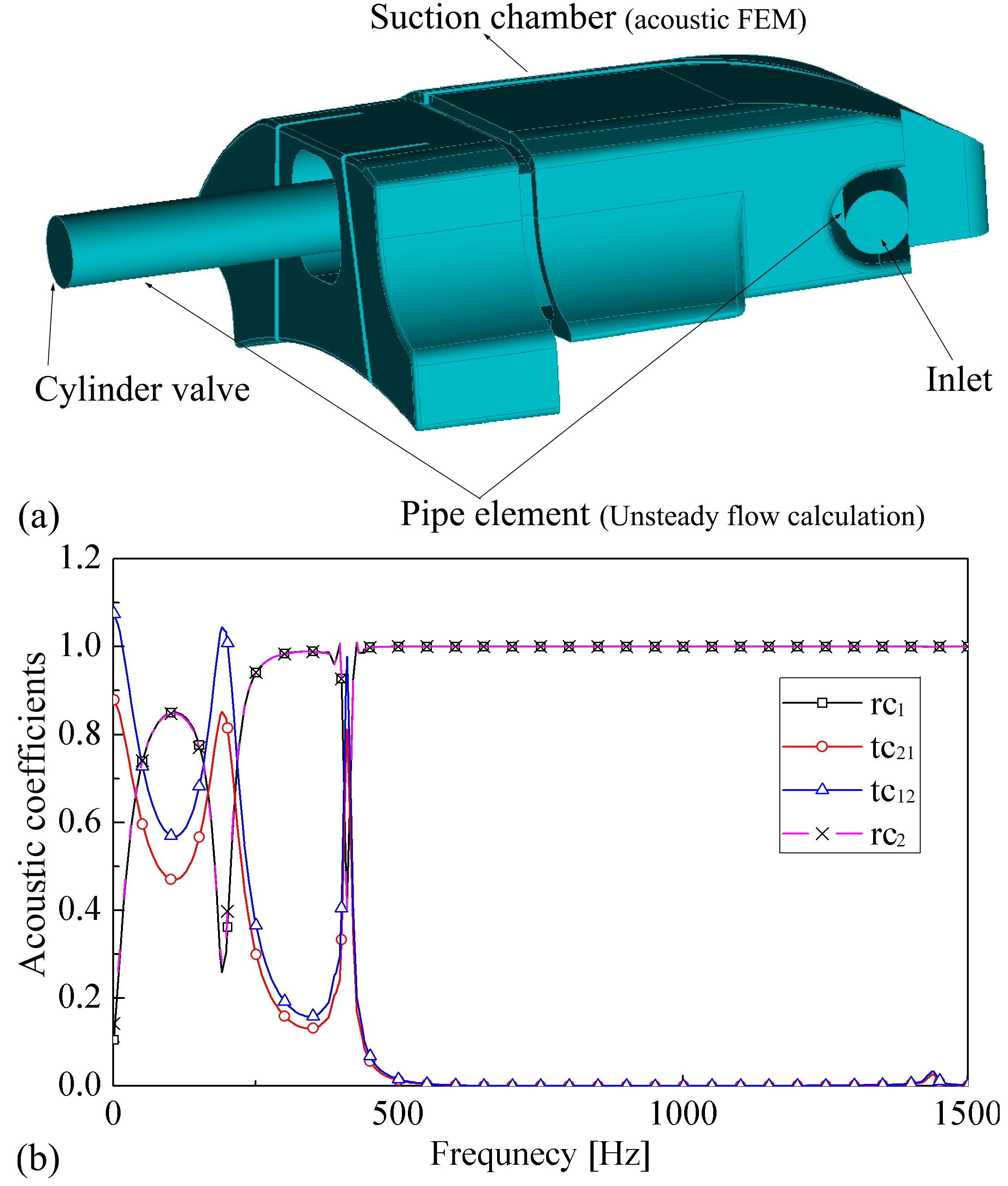
For further assess and verify the proposed model, numerical predictions have been compared to experimental data from a refrigerator compressor with the working fluid R600a. Detail description about the experimental system is presented in previous published paper [4]. Due to the limitation of the experimental investigation, only the suction system is studied and the discharge system is modelled with constant pressure profiles. Figure 9 shows the tested compressor suction system. Due to the complexity of the geometries, the modelling of suction chamber with simple volume element could be very difficult and inaccurate. Consequently, the use of acoustic FEM modeling strategy is necessary to study the acoustic response of the chamber. The transmission and reflection coefficients of the tested suction chamber are computed and presented in Figure 9, in which boundary 1 is the pipe-end adjacent to cylinder valve and boundary 2 is the inlet pipe-end.
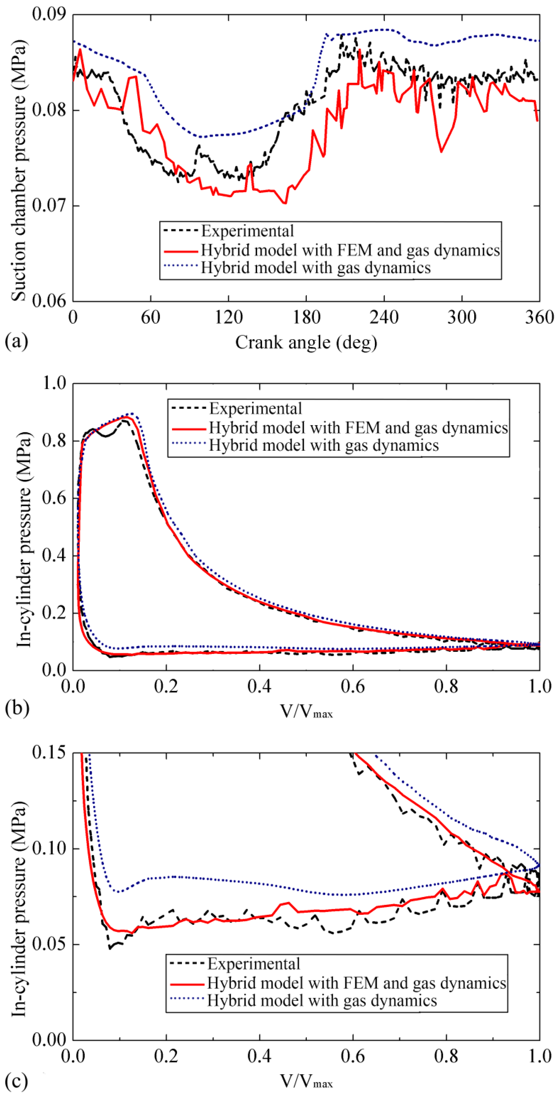
Figure 10a shows the comparison of the suction pressure profiles between the simulation and experiment. Through the figure, it can be highlighted that the new hybrid model demonstrates better agreement with experimental results compared to the hybrid model with gas dynamics. The latter model simplifies the complex chamber as a volume element with neglecting the pressure pulsations at high frequency and underestimating the pulsation amplitude. However, the new model is suitable for describing the high level of chamber details. The in-cylinder pressure variation between simulation and experiment is illustrated in Figure 10b. Generally, both the two models possess the potential of reproducing thermodynamic cycle. However, the new model can describe the trend of the measured in-cylinder pressure oscillation with a better agreement, the details of the suction phase, as shown in Figure 10c.

4. Conclusions

In this work, a hybrid linear/nonlinear model of a reciprocating compressor has been established to predict the in-cylinder thermodynamic cycle and pressure pulsations in pipelines system. Mass conservation equation and the first law of thermodynamics are solved in compressor sub-model. The pipe element with specific length and diameter is modeled based on 1D gas dynamics. An acoustic FEM characterization is described to model in detail the complex singularities such as chambers or attenuators. This characterization approach allows calculating transmission and reflection coefficients of the multi-port fluid domain. A hybrid algorithm is described to couple the mutual interaction of the three sub-models. Thus, the new hybrid model has the feature of putting together the main advantages of lumped parameter approach, 1D gas dynamics and acoustic FEM characterization. In this way, the model turns out to be an exceedingly helpful tool for evaluation of the mutual influence between compressor and pipelines, favoring shortening the system development process and reducing the cost of piping prototype development.
To highlight the advantages of the developed hybrid model, a comparison analysis between this model and the compressor model with gas dynamics has been carried out. Despite a good agreement between the two numerical models, the main advantage of the new model respect to the compressor model with gas dynamics is the involvement of the acoustic response dominated by compressor chambers. Moreover, the validity of the new model has been extensively confirmed by giving satisfactory predictions against previous experimental results.

Author Contributions

Conceptualization, Z.L. (Zhan Liu) and Z.L. (Zhujun Lan) and J.G.; methodology, Z.L. (Zhan Liu) and Z.L. (Zhujun Lan) and J.G.; validation, Z.L. (Zhan Liu), Y.X. and Z.D.; formal analysis, Z.L. (Zhan Liu) and J.Z. and X.C.; writing—original draft preparation, Z.L. (Zhan Liu); writing—review and editing, Z.L. (Zhan Liu) and Z.D.

Funding

This work was supported by the plan project of Qingdao applied basic research (17-1-1-93-jch), a program for the key research and development plan of Shandong Province (2017GGX40113) and the Province Natural Science Foundation of Shandong (ZR2017PEE001).

Conflicts of Interest

The authors declare no conflict of interest.

Nomenclature

Symbols
ttime (s)
mmass (kg)
ppressure (Pa)
Aarea (m2)
ρdensity (kg·m−3)
yvalve displacement (m)
Qheat in the control volume (J)
hspecific enthalpy (J·kg−1·K−1)
qfacoustic source power-flux per unit volume
Vvolume (m3)
Ttemperature (K)
ucharacteristic velocity (m·s−1)
Ddiameter (m)
r1crank radius (m)
r2length of connecting rod (m)
kkspring stiffness (N·m−1)
ADvalve plate area (m2)
Ginitpre-load force (N)
ceqdamping coefficient (N·s·m−1)
CDdrag coefficient
Usolution vector
Fflux vector
Bsource term vector
Gffriction term
rcreflection coefficient
tctransmission coefficient
Yacoustic impedance
asound speed (m·s−1)
σwave number
especific internal energy (J·kg−1)
aAentropy level (m·s−1)
qheat transferred between gas and
walls per unit of mass (W·kg−1)
YAcoustic impedance (kg·m−2·s−1)
Abbreviations
CFDcomputational fluid dynamics
3Dthree dimensional
1Done dimensional
0Dzero dimensional
FEMfinite element method
MOCmethod of characteristics
ESDEquivalent Short Duct
Greek symbols
φflow coefficient
αheat transfer coefficient (W·m−2·K−1)
ωangular speed (rad·s−1)
ξdamping factor
γspecific heat ratio
λ, βriemann variables
Δchange quantity
Superscripts
*acoustic properties
kperiod step
Subscripts
cvcontrol volume
ssuction
ddischarge
ppiston
clclearance
eqequivalent
rebrebound
impimpact
0stagnation state
FWforward
BWbackward
refreference condition
i, jport number of chamber

References

  1. Sharma, S.S. Determinants of carbon dioxide emissions: Empirical evidence from 69 countries. Appl. Energy 2011, 88, 376–382. [Google Scholar] [CrossRef]
  2. Aigner, R. Internal Flow and Valve Dynamics in a Reciprocating Compressor. Ph.D. Thesis, Technische Universität Wien, Vienna, Austria, 2007. [Google Scholar]
  3. Kim, S.; Cheong, C.; Park, J.; Kim, H.; Lee, H. Investigation of flow and acoustic performance of suction mufflers in hermetic reciprocating compressor. Int. J. Refrig. 2016, 69, 74–84. [Google Scholar] [CrossRef]
  4. Wang, T.; Guo, Y.; He, Z.L.; Peng, X.Y. Investigation on the delayed closure of the suction valve in the refrigerator compressor by FSI modeling. Int. J. Refrig. 2018, 91, 111–121. [Google Scholar]
  5. Damle, R.; Rigola, J.; Perez-Segarra, C.D.; Oliva, A. Object-oriented simulation of reciprocating compressor: Numerical verification and experimental comparison. Int. J. Refrig. 2011, 34, 1989–1998. [Google Scholar] [CrossRef]
  6. Yang, B.; Bradshaw, C.R.; Groll, A.A. Modelling of a semi-hermetic CO2 reciprocating compressor including lubrication submodels for piston rings and bearings. Int. J. Refrig. 2013, 36, 1925–1937. [Google Scholar] [CrossRef]
  7. Liu, Z.; Cao, X.; Wang, T.; Jia, W.G.; Duan, Z.Y. Comparative evaluation of the refrigeration compressor performance under different valve parameters in a trans-critical CO2 cycle. Int. J. Refrig. 2019, 101, 34–46. [Google Scholar] [CrossRef]
  8. Farzaneh-Gord, M.; Niazmand, A.; Deymi-Dashtebayaz, M.; Rahbari, H.R. Effects of natural gas compositions on CNG (compressed natural gas) reciprocating compressors performance. Energy 2015, 90, 1152–1162. [Google Scholar] [CrossRef]
  9. Tuhovcak, J.; Hejcik, J.; Jicha, M. Comparison of heat transfer models for reciprocating compressor. Appl. Therm. Eng. 2016, 103, 607–615. [Google Scholar] [CrossRef]
  10. Elson, J.P.; Soedel, W. A review of discharge and suction line oscillation research. In Proceedings of the Purdue Compressor Technology Conference, West Lafayette, IN, USA, 25–27 July 1972. [Google Scholar]
  11. Zhou, W.; Kim, J.; Soedel, W. New iterative scheme in computer simulation of positive displacement compressors considering the effect of gas pulsations. ASME J. Mech. Des. 2001, 123, 282–288. [Google Scholar] [CrossRef]
  12. Keith, N. Influence of shell volume on pressure pulsations in a hermetic reciprocating compressor. In Proceedings of the International Compressor Engineering Conference at Purdue, West Lafayette, IN, USA, 14–17 July 2014. [Google Scholar]
  13. Stiaccini, I.; Galoppi, G.; Ferrari, L.; Ferrara, G. A reciprocating compressor hybrid model with acoustic FEM characterization. Int. J. Refrig. 2016, 63, 171–183. [Google Scholar] [CrossRef]
  14. Stiaccini, I.; Galoppi, G.; Ferrari, L.; Ferrara, G. A hybrid time-frequency domain approach for numerical modeling of reciprocating compressors. Energy Procedia 2015, 81, 1102–1112. [Google Scholar] [CrossRef]
  15. Benson, R.S. The Thermodynamics and Gas Dynamics of Internal Combustion Engines; Clarendon Press: Oxford, UK, 1982. [Google Scholar]
  16. Xu, B.; Feng, Q.K.; Yu, X.L. Prediction of pressure pulsation for the reciprocating compressor system using finite disturbance theory. ASME J. Vibr. Acoust. 2009, 131, 031007. [Google Scholar] [CrossRef]
  17. Liu, Z.; Duan, Z.Y. Development of a transient gas dynamic model for the simulation of pulsation in reciprocating compressor piping systems. Proc. IMechE. Part E J. Process Mech. Eng. 2018, 232, 685–695. [Google Scholar]
  18. Brun, K.; Nored, M.G.; Rainer, K. Impact of piping impedance and acoustic characteristics on centrifugal compressor surge and operating range. ASME J. Eng. Gas. Turbines Power 2014, 137, 032603. [Google Scholar] [CrossRef]
  19. Lemmon, E.W.; Huber, M.L.; McLinden, M.O. NIST Standard Reference Database 23: Reference Fluid Thermodynamic and Transport Properties-REFPROP, Version 9.1; NIST: Gaithersburg, MA, USA, 2013.
  20. Roskosch, D.; Venzik, V.; Atakan, B. Thermodynamic model for reciprocating compressors with the focus on fluid dependent efficiencies. Int. J. Refrig. 2017, 84, 104–116. [Google Scholar] [CrossRef]
  21. Belman-Flores, J.M.; Ledesma, S.; Barroso-Maldonado, J.M.; Navarro-Esbrí, J. A comparison between the modeling of a reciprocating compressor using artificial neural network and physical model. Int. J. Refrig. 2015, 59, 144–156. [Google Scholar] [CrossRef] [Green Version]
  22. Wang, Y.; Xue, C.; Jia, X.H.; Peng, X.Y. Fault diagnosis of reciprocating compressor valve with the method integrating acoustic emission signal and simulated valve motion. Mech. Syst. Signal Process 2015, 56–57, 197–212. [Google Scholar] [CrossRef]
  23. Gascon, L.; Corberan, J.M. Construction of second-order TVD schemes for nonhomogeneous hyperbolic conservation laws. J. Comput. Phys. 2001, 172, 261–297. [Google Scholar] [CrossRef]
  24. Payri, F.; Desantes, J.M.; Torregrosa, A.J. Acoustic boundary condition for unsteady one-dimensional flow calculations. J. Sound Vib. 1995, 188, 85–110. [Google Scholar] [CrossRef]
  25. Serrano, J.R.; Climent, H.; Piqueras, P.; García-Afonso, O. Analysis of shock capturing methods for chemical species transport in unsteady compressible flow. Math. Comput. Model 2013, 57, 1751–1759. [Google Scholar] [CrossRef]
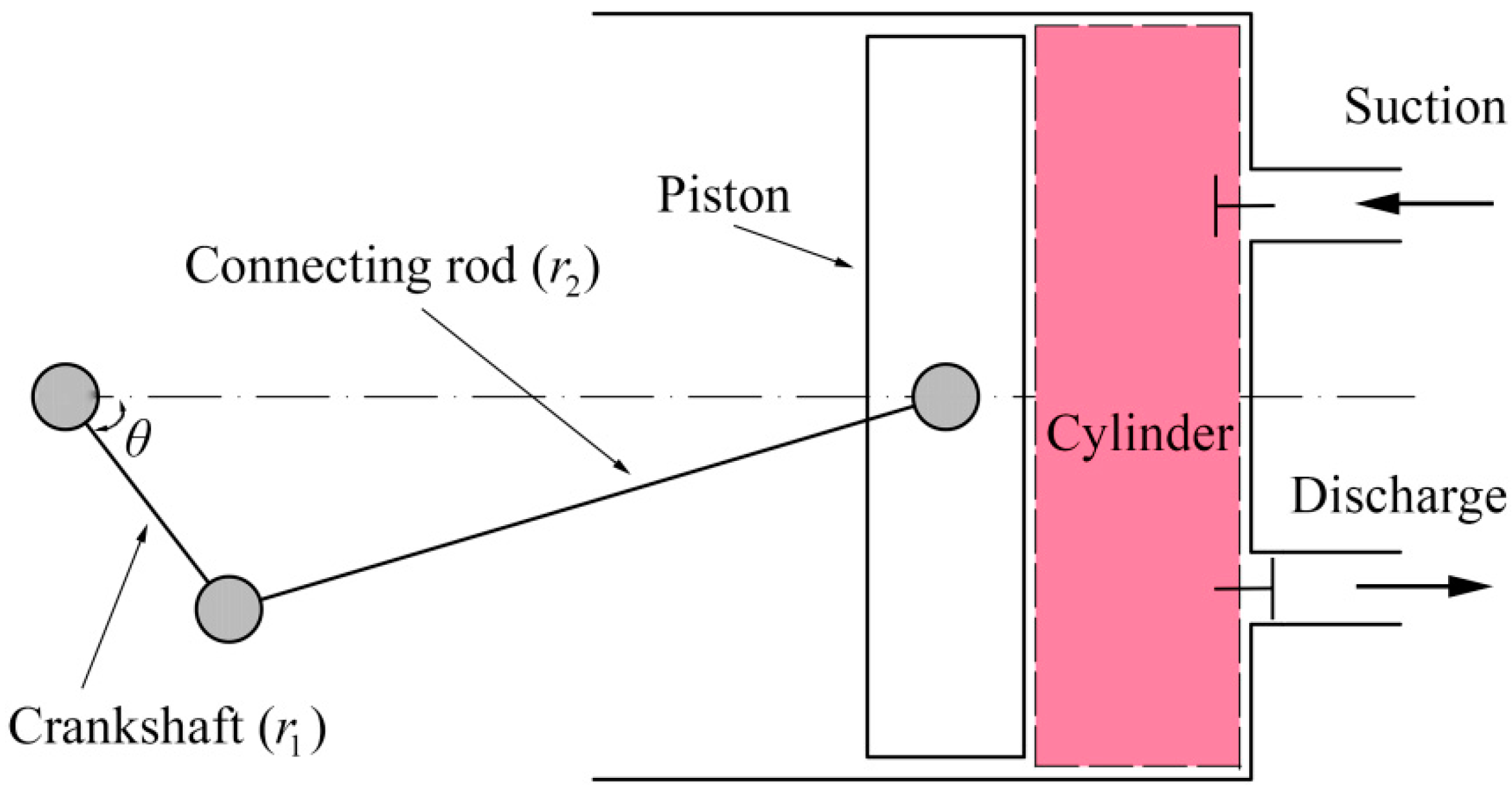
Figure 1. Schematic of reciprocating compressor sub-model.
Applsci 09 01179 g001
Figure 2. Schematic acoustic description of a multi-port configuration.
Applsci 09 01179 g002
Figure 3. Schematic description of the compressor hybrid model.
Applsci 09 01179 g003
Figure 4. Flowchart of the hybrid model programme layout.
Applsci 09 01179 g004
Figure 5. The examined chamber: (a) fluid domain and (b) finite element mesh.
Applsci 09 01179 g005
Figure 6. Amplitude of the transmission and reflection coefficients of discharge chamber with particle velocity imposed on the boundary of head-end valve.
Applsci 09 01179 g006
Figure 7. Comparison of: (a) pressure profile and (b) amplitude-frequency characteristics at the suction pipe-end; (c) pressure profile and (d) the amplitude-frequency characteristics at the discharge pipe-end.
Applsci 09 01179 g007
Figure 8. Comparsion of in-cylinder pressure oscillations between the hybrid model with FEM and gas dynamics and the hybrid model with gas dynamics.
Applsci 09 01179 g008
Figure 9. Case 2: (a) compressor suction system; (b) amplitude of transmission and reflection coefficients.
Applsci 09 01179 g009
Figure 10. Comparsion of the predictions with experimental results: (a) suction pressure profiles; (b) in-cylinder pressure oscillations of a cycle and (c) suction phase detail.
Applsci 09 01179 g010
Table 1. Main specifications of the reciprocating compressor.
SpecificationValueUnit
Rotational speed950rpm
Cylinder diameter105mm
Stroke110mm
Diameter of the pipeline50mm
Length of suction pipe0.47m
Length of discharge pipe0.65m
Suction temperature304.15K
Suction pressure0.802MPa
Discharge pressure2.1MPa
Discharge temperature367.15K